JP4119491B2 - Overcurrent protection circuit - Google Patents
Overcurrent protection circuit Download PDFInfo
- Publication number
- JP4119491B2 JP4119491B2 JP50266099A JP50266099A JP4119491B2 JP 4119491 B2 JP4119491 B2 JP 4119491B2 JP 50266099 A JP50266099 A JP 50266099A JP 50266099 A JP50266099 A JP 50266099A JP 4119491 B2 JP4119491 B2 JP 4119491B2
- Authority
- JP
- Japan
- Prior art keywords
- voltage
- current
- circuit switch
- detection means
- circuit
- Prior art date
- Legal status (The legal status is an assumption and is not a legal conclusion. Google has not performed a legal analysis and makes no representation as to the accuracy of the status listed.)
- Expired - Lifetime
Links
Images


Classifications
-
- H—ELECTRICITY
- H02—GENERATION; CONVERSION OR DISTRIBUTION OF ELECTRIC POWER
- H02H—EMERGENCY PROTECTIVE CIRCUIT ARRANGEMENTS
- H02H3/00—Emergency protective circuit arrangements for automatic disconnection directly responsive to an undesired change from normal electric working condition with or without subsequent reconnection ; integrated protection
- H02H3/02—Details
- H02H3/025—Disconnection after limiting, e.g. when limiting is not sufficient or for facilitating disconnection
-
- H—ELECTRICITY
- H02—GENERATION; CONVERSION OR DISTRIBUTION OF ELECTRIC POWER
- H02H—EMERGENCY PROTECTIVE CIRCUIT ARRANGEMENTS
- H02H9/00—Emergency protective circuit arrangements for limiting excess current or voltage without disconnection
- H02H9/02—Emergency protective circuit arrangements for limiting excess current or voltage without disconnection responsive to excess current
- H02H9/026—Current limitation using PTC resistors, i.e. resistors with a large positive temperature coefficient
Landscapes
- Engineering & Computer Science (AREA)
- Power Engineering (AREA)
- Emergency Protection Circuit Devices (AREA)
- Amplifiers (AREA)
Abstract
Description
本発明は、電気回路の過電流防止に関する。
PTC回路保護装置は周知である。特に有益なPTC装置は、PTC導電性ポリマー、即ち(1)有機ポリマーと、(2)当該ポリマー内に分散または分布されている、好ましくはカーボンブラックである粒状の導電性充填材とで構成されるPTC素子を含んでいる。PTC導電性ポリマー及びこれを含む装置は、例えば米国特許第4,237,441号、第4,238,812号、第4,315,237号、第4,317,027号、第4,426,633号、第4,545,926号、第4,689,475号、第4,724,417号、第4,774,024号、第4,780,598号、第4,800,253号、第4,845,838号、第4,857,880号、第4,859,836号、第4,907,340号、第4,924,074号、第4,935,156号、第4,967,176号、第5,049,850号、第5,089,801号、第5,378,407号に記述されている。
国際公報第WO 97/10637号は、比較的小さい過電流から回路を保護しなければならない場合に特に有益な過電流防止システムを開示している。こうしたシステムでは、制御素子と回路中断素子とが負荷と直列に配置されている。制御素子は回路中断素子と機能的に連結されており、回路内の電流が予め決められた量を超過すると、制御素子は過電流を検出して、回路中断素子を比較的導電性である状態から比較的非導電性である状態(完全な開状態を含む)へと変更させる。国際公報第WO 97/10637号に記述されているタイプのシステムの展開において、私達は、電力供給と電気負荷との間に接続可能であって動作回路を形成し、またこうして接続された場合に過電流から回路を保護する新規電気システムを発見した。この新規システムは、以下で本発明の第1及び第2の面として別個に記述する2つの重複するカテゴリーに入る。
発明の第1の面
本発明の第1の面によるシステムは、
(1)(a)通過する電流が正常電流、INORMAL、から予め決められた電流量が超過するまでには至っていない、電流が不活性化された状態と、
(b)通過する電流が予め決められた電流量だけ正常電流、INORMAL、を超過している、電流が活性化された状態と
を有する電流検出手段と、
(2)電流検出手段に接続され、
(a)電流検出手段が電流の不活性化状態にある場合に閉じられ、
(b)電流検出手段が電流の活性化状態にある場合に開けられる
第1の回路スイッチと、
(3)(a)印加される電圧が予め決められた電圧量を超過していない、電圧が不活性化された状態と、
(b)印加される電圧が予め決められた電圧量を超過している、電圧が活性化された状態と
を有する電圧検出手段と、
(4)PTC装置と、
(5)電圧検出手段に接続され、
(a)電圧検出手段が電圧の不活性化状態にある場合に閉じられ、
(b)電圧検出手段が電圧の活性化状態にある場合に開けられる
第2の回路スイッチとを備え、
第1の回路スイッチとPTC装置とは互いに並列に接続され、
第2の回路スイッチは、第1の回路スイッチ及びPTC装置による並列接続と直列に接続され、
電圧検出手段は、(i)第2のスイッチ、及び(ii)第1の回路スイッチとPTC装置との並列の組合せ、の直列の組合せと並列に接続されている。
添付の図面において、図1には、こうしたシステムを含んだ回路の一例が示されている。この新規システムは、国際公報第WO 97/10637号の図2cが示すシステムに類似しているが、第2の回路スイッチが開くとシステム電圧が電圧検出手段に送られるという優位点を有している。これは、第2の回路スイッチが引き続き開放され、開放状態を維持することを保証する。国際公報第WO 97/10637号の図2cが示すシステムは、第2の回路スイッチが開くと電圧検出手段から電圧が除去されるという欠点を有している。これは、従来型のリレーの接点の「チャタリング」を引き起こす可能性があり、メークビフォアブレークリレーの使用など、これを防止するための何らかの手段を使用しなければならなくなる。
リレーが活性化(場合により、たとえば、通常の開位置から閉位置への切換または通常の閉状態から開状態への切換)するレベル(場合により、電流または電圧)は、しばしば「プルイン」レベルと呼ばれる。同様に、リレーが不活性化(場合により、たとえば、閉位置から通常の開位置への切換、或いは開位置から通常の閉位置への切換)するレベル(場合により、電流または電圧)は、しばしば「ドロップアウト」レベルと呼ばれる。
この種のシステムでは、所望される過電流防止を提供するために、電流検出用リレー(または他の検出手段)は、運転電流レベルの最大値を超過し過ぎないような(例えば、最大値の5倍を越えない、特には3倍を越えない、また特には2倍を越えない)プルインレベルを有することが望ましい。またこの種のシステムでは、短期の過渡的過電流に対する保護システムのトリガーを回避するため、電流検出用リレー(または他の検出手段)は、運転電流レベルの最大値を超過し過ぎないようなドロップアウトレベルを有することが望ましい。これは、図2Aと図2Bが示す曲線で説明されている。図2Aが示す曲線の場合、電流検出手段のドロップアウトレベルは、回路の正常な動作レベルより下位である。従って過渡電流が発生した場合、図2Aが示すように、電流検出手段は、過渡電流がプルインレベルを超過するとプルインするが、正常な動作電流レベルはドロップアウトレベルよりも上であるため、電流検出手段はドロップアウトせず、活性化された状態であり続ける。この種の保護システムでは、これによりPTC装置が加熱されてその抵抗が増加するため、電圧検出用リレー(または他の第2の回路スイッチ)が開くことになる。
こうした状況を回避するため、即ちこうした過渡電流のトリガーを防止するため、電流検出用リレーのプルインレベル及びドロップアウトレベルは図2Bが示すような関係性を有することが可能である。図2Bが示す曲線の場合、電流検出手段のドロップアウトレベルは回路の正常な動作レベルよりも上位である。従って過渡電流が発生した場合、図2Bが示すように、電流検出用リレーは過渡電流がプルインレベルを超過するとプルインするが、電流がまたドロップアウトレベルより下に戻ると急激にドロップアウトする。電流検出用リレーがきわめて短時間プルインしても、PTC装置は電圧検出用リレーを開かせるまでには加熱されない。このため、保護システムは過渡電流に対して起動しない。
電流検出用リレーの接点が開かれると、PTC装置は、PTC装置を通じる電圧が電圧検出用リレーのプルインに必要なレベルに到達する前に、電流検出用リレーのドロップアウトレベルより下のレベルまで電流を低減させるという危険性のあることが発見されている。電流検出用リレーがドロップアウトすると、接点が再び閉じ、これにより故障電流が回復して電流検出用リレー接点の開閉サイクルが継続的に反復される可能性がある。この「バシング」または「チャタリング」は、接点同士が溶断する原因となり得る。この問題は、十分に低い値のプルイン電圧を有する単一の電圧検出用リレーを使用すること(同時に上述のドロップアウトレベル要件に従うこと)では克服することができない。これは、こうしたリレーに使用されるコイルは必ず非常に細いワイヤで製造されていて、通常のシステム電圧、または並列するAC電力線における照明によって又は切換過渡電流との誘導結合によって誘導されるサージに曝されると溶断する可能性があるためである。
本発明の第1の面による好ましい実施形態は、この問題に対する解決を提供する。
1つの実施形態では、電圧検出用リレーは、回路内の電流が電流リレーのドロップアウト電流より下に降下するまでに電圧接点が開くことを保証するだけの低いプルイン電圧を有するラッチリレーである。第2のラッチリレーは、第1のリレーと並列に配置されていて、第1のリレーより高いプルイン電圧を有し、両リレーを切断する接点を制御する。ラッチDCリレーの方がラッチACリレーよりも入手しやすいことから、ラッチリレーの少なくとも1つ、好ましくは双方がDCリレーである。この解法によれば電流リレー接点のチャタリングが防止されるだけでなく、下流電流及び電圧リレーが絶縁され、このため現場作業員にとって回路がより安全なものとなり、照明または他のサージによって保護システム及び他の回路構成素子が損傷されないことが保証される。
他の好ましい実施形態は、各々が電圧リレーと並列でありかつ互いに並列である、累進的に高いプルイン電圧を有する複数の追加の電圧リレーを加えるというものである。最高のプルイン電圧を有する電圧リレーは、通常のシステム電圧では損傷されないコイルを有している。各々の追加の電圧リレーは、「原初の」電圧リレーと追加的な電圧リレーまたは低位のプルインレベル電圧を有するリレーとの接続を完全に断つスイッチを制御する。
本発明の第1の面は、添付の図面の図1〜図5に示されている。そのうちの図1、図3、図4及び図5は、本発明の第1の面による回路の回路図であり、図2aと図2bは、過渡電流状況に応答した電流検出用リレーの異なるプルインレベル及びドロップアウトレベルの効果について説明している。
図1は、PTC装置18と、電流検出用リレー14と、第1の電圧検出用リレー22とを含む回路を示している。電流検出用リレー14は第1組の接点16に結合され、第1の電圧検出用リレー22は第2組の接点24に結合されている。電流検出用リレー14は、回路内の電流を感知する機能を実行する。電流検出用リレー14は、過電流状態を検出すると第1組の接点16を開放し、電流をPTC装置18へと転じる。一般に、PTC装置18の抵抗は第1の電圧検出用リレー22の抵抗よりも小さいため、大部分の電流はPTC装置18を通じて流れる。PTC装置18は、抵抗を増加して回路10内の電流を制限し、第1の電圧検出用リレー22に電圧を印加する。第1の電圧検出用リレー22に印加される電圧が第1の電圧検出用リレー22の活性化に必要なレベルにまで到達すると、第1の電圧検出用リレー22は第2組の接点24を開く。これにより、システム電圧は電圧リレーコイルへと伝達され、こうして電圧コイルが活性化されている間は接点24が開状態のままであることが保証される。電流は負荷及び第1の電圧検出用リレー22を通じて流れ続けるが、電圧リレー22の抵抗によって制限される。電圧コイルを通じる電流を中断すれば回路をリセットすることが可能であり、これは、手動のリセット機構または遠隔操作が可能なリセットコイル(いずれも図1には示されていない)によって行うことができる。
図3の回路は、並列に結合された2つの電圧検出用リレー22、28を使用している。第1のラッチ電圧検出用リレー22は、回路内の電流が電流検出用リレー14のドロップアウトレベルより下に降下するまでに第2組の接点24が開くことを保証するだけの低いプルイン電圧を有している。第2の電圧検出用リレー28は、第1の電圧検出用リレー22よりも高いプルイン電圧を有し、電圧検出用リレー22、28双方を回路から断つ第3組の接点32を制御する。
図4が示す別の回路では、3以上(図4には3つが示されている)の電圧検出用リレー22、42、44が並列に結合されている。連続する電圧検出用リレーコイルは各々、先行するコイルより高いプルイン電圧を有し、並列のアッセンブリを通じた電圧が増大するにつれてリレーコイルが連続して活性化し、連続する各リレーが先行するリレーを回路から断つ。従って、アッセンブリ内のその最終のリレーのみが全システム電圧を通せばよい。
図5が示す回路では、図3の電圧リレー22の代わりに第1のラッチDC電圧リレー76が使用されている。第1のラッチDC電圧リレー76は2つのコイル52、54を有していて、第1のセットコイル52は第1のラッチDC電圧リレー接点24を開位置に切換し、第1のリセットコイル54は第1のラッチDC電圧リレー接点24を閉位置に戻す。ブリッジ回路72は、ACを整流DCに変換する。PTC装置18を通じる電圧が第1のセットコイル52のプルイン電圧まで増大すると、第1のセットコイル52が活性化して第1のラッチDC電圧リレー接点24を開回路位置に切換させる。第1のラッチDC電圧リレー76は、この位置でラッチする。
また、第2のラッチDC電圧リレー78も、2つのコイル56、58を有していて、第2のセットコイル56は2組の接点68、74を切換し、第2のリセットコイル58は2組の接点68、74をリセットする。第2のセットコイル56は、第1のセットコイル52より高いプルイン電圧を有している。第1のラッチDC電圧リレー接点24が開けば、ブリッジ回路72を通じる電圧は上昇する。電圧が上って第2のセットコイル56のプルイン電圧に到達すると、第2のセットコイル56が活性化される。2組の接点68、74が交換し、ブリッジ回路72がAC入力から断路され、これにより両リレーのセットコイル52、56が不活性化される。第1のコンデンサ82は、システム電圧が除去された後に切換動作を完了する。
切換の終わりでは、両電圧検出用リレー76、78の接点24、68、74は開状態にあり、入力から出力へとゼロ電流が流れる。回路のこのトリップ状態では電力は消費されず、下流の負荷はシステム電圧から電気的に絶縁されている。これは、現場作業員に対しては危険性のより少ない状態を提供し、照明及び他の過渡電流ソースから精密な巻線を保護する。
2組の接点68、74がそのセット位置に切り換わると、第1と第2のリセットコイル54、58がブリッジ回路72に接続される。回路のリセットは、例えば押しボタン64によって手動で、もしくは追加のリレーコイル62及び付属の接点66によって遠隔的に行うことができる。いずれかの手段によるリセットは、ブリッジ回路72を通じる電力を第1と第2のリセットコイル54、58に接続する。リレーコイルに対するアークまたは損傷の原因となり得る過電圧状態を防止するために、抵抗器84を包むことができる。
発明の第2の面
本発明の第1の面についての上述の説明において好ましい例によって開示されている特定の電流検出手段は、電流検出用リレーである。私達は、状況によっては、電流検出用リレーは電流検出手段として好ましくないことを発見した。例えば、故障状態が断続的または反復的な電流サージを引き起こす場合には、電流リレーは満足のいかない方法で急激に活性化され、また不活性化されるという結果になる可能性がある。本発明の第2の面では、本発明の第1の面についての上述の説明に開示された全ての回路において使用可能な、また故障状態が断続的または反復的な回路サージを生成する可能性のある場合に特に有益である代替の電流検出手段を私達は発見した。この電流検出手段は、電流の大きさだけでなくその持続時間にも応答し(従って、例えばこれは、電流が予め決められたレベルを1ミリ秒より長く超過しない限り、第1の回路スイッチを閉位置から開位置へと切換しない)、よって電流の大きさ及び持続時間の関数が予め決められた値を超過した場合にのみ、負荷への電流が遮断または低減されることを保証する。
また本発明の第2の面によれば、第2のスイッチが開状態でラッチしているなら、構成素子(1)〜(5)は異なる構成に配置可能であること、即ち第1の回路スイッチ、PTC装置及び電圧検出手段は並列に接続され、第2の回路スイッチと第1の回路スイッチ、PTC装置及び電圧検出手段による並列接続とは直列に接続され得ることを私達は発見した。
1つの実施形態では、本発明の第2の面は、電力供給と電気的負荷との間に直列に接続されることが可能であって1つの動作回路を形成し、こうして接続された場合に回路を過電流から保護する電気的保護システムを提供している。本システムは、正常な動作条件と故障条件とを有し、
(1)(a)負荷を通過する電流の大きさの関数が予め決められた値を超過していない、電流が不活性化された状態と、
(b)過電流によって前記関数が前記予め決められた値を超過させられる、電流が活性化された状態と
を有する電流検出手段と、
(2)(a)開状態及び閉状態を有し、
(b)電流検出手段に結合されている
第1の回路スイッチであって、第1の回路スイッチが閉位置にあり、かつ前記関数が前記予め決められた値より下から上に増大すると第1の回路スイッチが開状態に切換される第1の回路スイッチと、
(3)(a)印加される電圧が予め決められた電圧量を超過していない、電圧が不活性化された状態と、
(b)印加される電圧が予め決められた電圧量を超過している、電圧が活性化された状態と
を有する電圧検出手段と、
(4)PTC装置と、
(5)(a)開状態及び閉状態を有し、
(b)電圧検出手段に結合されている
第2の回路スイッチであって、第2の回路スイッチが閉位置にあり、かつ電圧検出手段が電圧の不活性化された状態から電圧が活性化された状態へと切換されると、第2の回路スイッチは閉状態から開状態へと切換される第2の回路スイッチと
を備え、
これらの構成素子(1)〜(5)は、
(A)第2の回路スイッチが、第1の回路スイッチとPTC装置との並列の組合せと直列に接続され、電圧検出手段が、(i)第2のスイッチ及び(ii)第1の回路スイッチとPTC装置との並列の組合せによる直列の組合せと並列に接続されるように、または、
(B)第1の回路スイッチ、PTC装置及び電圧検出手段が互いに並列に接続され、第2の回路スイッチと、第1の回路スイッチ、PTC装置及び電圧検出手段による並列の組合せとが直列に接続され、第2の回路スイッチが開位置でラッチするスイッチであるように接続されている。
他の実施形態では、本発明の第2の面は、電源と、電気的負荷と、本発明の第2の面の第1の実施形態による電気的保護システムを備えた電気回路を提供している。
本発明の第2の面は、添付の図面の図6〜図10に示されている。そのうちの図6と図7は、本発明の回路の回路図であり、図8、図9及び図10は、本発明の回路部分の回路図である。
本発明の第2の面の好ましい1つの実施形態では、電流検出手段は、
(i)負荷を通過する電流の前記関数に関連する信号電圧を提供する電圧出力と、
(ii)基準電圧を供給する電圧源と、
(iii)信号電圧と基準電圧との間の比較を行ない、比較の結果を反映した出力を提供する比較器と
を備えている。
信号電圧は、例えば、負荷を通過する電流に比例する電流が流れる抵抗器を通じた電圧、または負荷を通過する電流に比例する電流が流れる、導線に結合された変流器からの電圧、または負荷を通過する電流に比例する電流が流れる、導線に結合された磁気抵抗装置からの電圧である。
本発明の第2の面の最も単純な実施形態では、負荷を通過する電流の関数は、単純にその電流の大きさである(全ての電流検出手段に固有の特性、即ち過電流パルスは余りに短かいものである可能性があり、電流検出手段はこれを予め決められた最小値より大きい大きさを有するものとして認識しないことによる)。他の実施形態では、この関数は、(i)負荷を通過する電流の大きさ、及び(ii)負荷を通過する電流の持続時間の関数であり、この関数は、電流検出手段自体に固有のもの以外の何か(例えば、過電流の持続時間が1ミリ秒未満、または25ミリ秒未満、または50ミリ秒未満、または100ミリ秒未満であれば予め決められた値が超過され得ないような関数)である。その代り、または追加的に、電流検出手段は、予め決められた値を変更するようにプログラムされ、及び/または適応性のあるもの、即ち電流(または他の変数)を一定期間観測し、観測期間中の電流(または他の変数)に応答して予め決められた値を設定するものである。
本発明の第2の面の種々の実施形態においては、第1のスイッチと第2のスイッチのうちの一方が開状態でラッチするスイッチであって他方が非ラッチスイッチである場合もあれば、双方がラッチスイッチである、或いは双方が非ラッチスイッチである場合もある。ある実施形態では、構成素子(1)〜(5)は前記パラグラフ(A)に従って接続されており、第2の回路スイッチは、開状態に切換されてもこの状態ではラッチしない。これは、過電流の原因が除去されれば回路は正常動作に復帰するという優位点を有している。他の実施形態では、構成素子(1)〜(5)は前記パラグラフ(B)に従って接続されており、第1と第2の回路スイッチは各々、閉状態から開状態に切換されれば開状態でラッチする。これは、過電流が保護システムをトリガーした後は電流が負荷を流れないという優位点を有しているものの、過電流の原因が除去された後であっても正常動作が回復可能となる前には両スイッチをリセットしなければならないという欠点を有している。しかし、システムが基準電圧を有する、及び/またはプログラム可能な、及び/または適応性のある電流検出手段を使用している場合は、スイッチを例えば電気信号によって遠隔的にリセットすることが可能であって手動でリセットする必要のないシステムを設計することは困難ではない。
本発明の第2の面による好ましい保護システムは、
(1)(a)(i)負荷を通過する電流の大きさ、及び(ii)負荷を通過する電流の持続時間の関数が予め決められた値を超過していない、電流が不活性化された状態と、
(b)過電流によって前記関数が前記予め決められた値を超過させられる、電流が活性化された状態と
を有する電流検出手段であって、
(i)前記関数に関連する信号電圧を生成する電圧出力と、
(ii)基準電圧を供給する電圧源と、
(iii)信号電圧と基準電圧との間の比較を行ない、比較の結果を反映した出力を提供する比較器と
を備える電流検出手段と、
(2)(a)開状態および閉状態を有し、
(b)電流検出手段に結合されている
第1の回路スイッチであって、第1の回路スイッチが閉位置にあり、かつ前記関数が前記予め決められた値より下から上に増大すると、比較器からの出力が第1の回路スイッチを閉状態から開状態に転換する第1の回路スイッチと、
(3)(a)印加される電圧が予め決められた電圧量を超過していない、電圧が不活性化された状態と、
(b)印加される電圧が予め決められた電圧量を超過している、電圧が活性化された状態と
を有する電圧検出手段と、
(4)PTC装置と、
(5)(a)開状態及び閉状態を有し、
(b)電圧検出手段に結合されている
第2の回路スイッチであって、第2の回路スイッチが閉位置にあり、かつ電圧検出手段が電圧の不活性化された状態から電圧が活性化された状態へと転換されると、第2の回路スイッチは閉状態から開状態へと切換されて開状態においてラッチする第2の回路スイッチと
を備え、
第1の回路スイッチ、PTC装置及び電圧検出手段は互いに並列に接続され、第1の回路スイッチ、PTC装置及び電圧検出手段によるこの並列の組合せと第2の回路スイッチとは直列に接続されている。この回路において、好ましくは、
(a)第1の回路スイッチは、通常は閉じられていて開状態でラッチする第1のリレーであり、
(b)第2の回路スイッチは、通常は閉じられていて開状態でラッチする第2のリレーであり、
(c)比較器からの出力は、前記関数が前記予め決められた値より上から下へと増大すると、通常は開いていて閉状態ではラッチしない第3のリレーを閉じ、こうして第1の回路スイッチを開く電流の流れを発生させ、
(d)電圧検出手段は、
(i)通常は開いていて閉状態でラッチする第4のリレーを備え、
(ii)電圧が不活性化された状態から電圧が活性化された状態へ転換されると第4のリレーを閉じ、こうして第2の回路スイッチを開く電流の流れを発生させる。
次に図を参照すると、図6は、電力源12と、負荷26と、第1及び第2の回路スイッチ16及び24と、PTC装置18と、電流検出手段14と、電圧検出手段22とを含む回路を示している。電流検出手段14は第1の回路スイッチ16に結合され、電圧検出手段22は第2の回路スイッチ24に結合されている。電流検出手段14は、回路内の電流を感知する。電流検出手段14は、過電流状態を検出すると開位置でラッチする第1の回路スイッチ16を開き、こうして電流を第1の回路スイッチ16と並列に接続されているPTC装置18へと転じる。一般に、PTC装置18の抵抗は電圧検出手段22の抵抗よりも小さいため、大部分の電流はPTC装置18を通じて流れる。PTC装置18は、抵抗を増加して回路内の電流を制限し、電圧検出手段22に電圧を印加する。電圧検出手段22に印加される電圧が予め決められたレベルにまで到達すると、電圧検出手段22は開状態でラッチする第2の回路スイッチ24を開く。
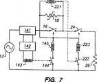
図7は、図6をいくぶんか詳細に示す。電流検出手段は、負荷を通って流れる電流の関数に比例する信号電圧を提供する電圧出力141を備えている。信号電圧は比較器142に送られ、比較器142はこの信号電圧を予め決められた基準電圧と比較して比較結果を反映した電流出力を提供し、この電流出力はリレーコイル143に送られ、リレーコイル143は通常は開状態であるリレー接点144を制御する。比較器からの出力が、負荷電流の関数が予め決められたレベルを超過しているという事実を反映している場合は、リレー接点144が閉じて電流がリレーコイル145を通じて流れ、これにより、開位置でラッチする第1の回路スイッチ16が開く。本電圧検出手段は、通常は開状態であるリレー接点222を制御するリレーコイル221を備えている。このコイルを通る電圧が予め決められた電圧量に到達すると、リレー接点222が閉じて電流はリレーコイル223を通じて流れ、これにより、開状態でラッチする第2の回路スイッチ24が開く。第1の回路スイッチが開状態でラッチするため、予め決められた電圧量は任意の適正レベルであること、典型的には第2の回路スイッチ24の遮断定格より下のレベルであることが可能である。
図7における種類の電流検出手段は、電磁式(電流リレーの場合等)ではなく電子式である。電子式の検出手段の使用は、システムを、例えばコンデンサ及び抵抗器の使用を通じて多様な異なる結果を生成するように、例えば電流にとってどんな平均時定数が所望されるかを取得するように、適合化させることを可能にする。例えば、故障電流が16ミリ秒で反復するサージを有する場合、電流リレーは同じ期間で反復する開動作及び閉動作に応答し、発振性の「ブザー」音を生成して潜在的に接点を損傷させる。電子的に制御される検出方法は、サージを100ミリ秒等のより長い時間期間に渡って平均化するために選択できる。従って、その出力は平滑化された値となり、基準値との比較が容易である。他の優位点として、回路の精密な動作がある。電子的な電流検出方法を使用すれば、動作のためのトリガー電流は、リレーの機械的構成素子の取付けにおける多様性を仮定すると、電流リレーを使用する場合に可能であるより遥かに精密に選定できる。また、親出願で論じられているような、プルイン電流とドロップアウト電流との整合について懸念する必要もない。
電子制御式電流検出の他の優位点は、ラッチ接点に関連して存在する低い電力損にある。こうした接点の操作には入力信号が必要であるが、これらはそのラッチされた位置にあり続けるため、後に除去されることが可能である。これは、正常な動作においては、回路は、接点の抵抗に直接関係する典型的には100ミリオームに近い低い値のもの以外には電力損を必要としないことを意味している。回路が動作し、接点がその開位置にラッチされると、この場合もやはりその位置を保持するために必要な継続的電力は存在しない。
その他の優位点は、照明サージが保護システムをトリガーしないことを保証するように時平均定数を選択可能であることにある。他の優位点は、システムを、「トリップされた」状態または開状態では、高電圧または「ホット」な導線と中性線(接地線)との間の経路、または「ホット」な導線の入力と出力との間の経路を含む全ての電流経路が開状態の接点によって中断されるように設計可能であることにある。
図7が示す電流センサタイプについては、2つの特徴を認識する必要がある。第1は、ラッチリレーに電力を供給するための中性線(接地線)を有する接点が必要とされることである。接地接点または低電圧接点は電源から入手可能であるため、一般にこれは困難な要求事項ではない。第2は、最小のシステム電圧が要求されることである。システム電圧(「ホット」な導線と中性線との間の電圧差)が第1と第2の回路スイッチの最小動作電圧より低い場合は、これらのリレースイッチは作動せず、故障電流が流れることがあっても回路は通電状態を保持する。これはこのタイプの防護装置が、例えばユティリティの電源と下流の電力供給との間で過電流故障が発生してもシステム電圧はリレーの動作電圧より下には下がらないような場合に使用可能であるが、短絡時にはその出力電圧が消耗する可能性のあるたとえば変圧器の2次側では使用してはならないことを意味している。
図8と図9は、図7における使用に適した電圧出力の回路図を示している。図8では、信号電圧は精密に知られている抵抗器1411を通じた電圧である。図9では、電圧出力は回路電流を運ぶ導線に結合された電流変換器1412を備え、誘導された電圧は、所望される時間期間に渡って電流を平均化して所望の電圧信号を提供するコンデンサ1413及び抵抗器1414を含む回路に供給される。
図10は、図7における使用に適した比較器の回路図を示している。比較器は、主要な電力源12またはバッテリから派生され得る3ボルト電源(またはこれに類似する低電圧)を使用している。抵抗器1424と1425は、演算増幅器1426の基準電圧を決定する。所望されれば、基準電圧を所望通りに変更できるように、抵抗器1424及び1425の一方または両方を可変抵抗器とすることができる。信号電圧が基準電圧を越えると、演算増幅器はトランジスタFETを起動させ、電流がリレーコイル143(必ず基準電圧によって作動する)を通って流れる。The present invention relates to prevention of overcurrent in an electric circuit.
PTC circuit protection devices are well known. A particularly useful PTC device consists of a PTC conductive polymer: (1) an organic polymer and (2) a granular conductive filler, preferably carbon black, dispersed or distributed within the polymer. PTC elements are included. PTC conductive polymers and devices containing the same are disclosed, for example, in U.S. Pat. Nos. 4,237,441, 4,238,812, 4,315,237, 4,317,027, and 4,426. 633, 4,545,926, 4,689,475, 4,724,417, 4,774,024, 4,780,598, 4,800,253 No. 4,845,838, No. 4,857,880, No. 4,859,836, No. 4,907,340, No. 4,924,074, No. 4,935,156, No. 4,967,176, No. 5,049,850, No. 5,089,801, No. 5,378,407.
International Publication No. WO 97/10737 discloses an overcurrent prevention system that is particularly useful when the circuit must be protected from relatively small overcurrents. In such a system, the control element and the circuit interruption element are arranged in series with the load. The control element is operatively connected to the circuit interruption element, and when the current in the circuit exceeds a predetermined amount, the control element detects an overcurrent and causes the circuit interruption element to be relatively conductive. To a relatively non-conductive state (including a fully open state). In the development of a system of the type described in International Publication No. WO 97/10737, we can connect between the power supply and the electrical load to form an operating circuit and thus be connected A new electrical system that protects the circuit from overcurrent was discovered. This new system falls into two overlapping categories, described separately below as the first and second aspects of the present invention.
First aspect of the invention
The system according to the first aspect of the invention comprises:
(1) (a) The passing current is a normal current, INORMAL, The state where the current is deactivated, which has not reached the predetermined amount of current,
(B) The passing current is a normal current by a predetermined amount of current, INORMAL, Exceeding, current activated state and
Current detection means having
(2) connected to the current detection means,
(A) closed when the current detection means is in a current inactive state;
(B) Opened when the current detection means is in a current activation state.
A first circuit switch;
(3) (a) the applied voltage does not exceed a predetermined voltage amount, the voltage is deactivated, and
(B) the applied voltage exceeds a predetermined voltage amount, the voltage is activated, and
Voltage detection means having
(4) a PTC device;
(5) connected to the voltage detection means,
(A) closed when the voltage detection means is in a voltage inactivated state;
(B) Opened when the voltage detection means is in the voltage activation state.
A second circuit switch;
The first circuit switch and the PTC device are connected in parallel to each other,
The second circuit switch is connected in series with the parallel connection by the first circuit switch and the PTC device,
The voltage detection means is connected in parallel with a series combination of (i) a second switch and (ii) a parallel combination of the first circuit switch and the PTC device.
In the accompanying drawings, FIG. 1 shows an example of a circuit including such a system. This new system is similar to the system shown in FIG. 2c of International Publication No. WO 97/10737, but has the advantage that the system voltage is sent to the voltage detection means when the second circuit switch is opened. Yes. This ensures that the second circuit switch continues to be opened and remains open. The system shown in FIG. 2c of WO 97/10637 has the disadvantage that the voltage is removed from the voltage detection means when the second circuit switch is opened. This can cause “chattering” of contacts in conventional relays and some means to prevent this must be used, such as the use of make-before-break relays.
The level (in some cases current or voltage) at which the relay is activated (eg, switching from a normal open position to a closed position or from a normal closed state to an open state) is often referred to as a “pull-in” level. be called. Similarly, the level (in some cases current or voltage) at which the relay is deactivated (in some cases, for example, switching from a closed position to a normal open position, or switching from an open position to a normal closed position) is often Called the “dropout” level.
In this type of system, in order to provide the desired overcurrent protection, the current detection relay (or other detection means) does not exceed the maximum value of the operating current level (eg, the maximum value). It is desirable to have a pull-in level that does not exceed 5 times, in particular does not exceed 3 times, and in particular does not exceed 2 times. Also, in this type of system, the current detection relay (or other detection means) drops so that the maximum operating current level is not exceeded to avoid triggering the protection system against short-term transient overcurrent. It is desirable to have an out level. This is illustrated by the curves shown in FIGS. 2A and 2B. In the case of the curve shown in FIG. 2A, the dropout level of the current detection means is lower than the normal operation level of the circuit. Therefore, when a transient current occurs, as shown in FIG. 2A, the current detection means pulls in when the transient current exceeds the pull-in level, but since the normal operating current level is above the dropout level, the current detection means The means do not drop out and remain activated. In this type of protection system, this heats up the PTC device and increases its resistance, thereby opening the voltage sensing relay (or other second circuit switch).
In order to avoid such a situation, that is, to prevent such a transient current from being triggered, the pull-in level and the drop-out level of the current detection relay can have a relationship as shown in FIG. 2B. In the case of the curve shown in FIG. 2B, the dropout level of the current detection means is higher than the normal operation level of the circuit. Therefore, when a transient current occurs, as shown in FIG. 2B, the current detection relay pulls in when the transient current exceeds the pull-in level, but suddenly drops out when the current returns below the drop-out level. Even if the current detection relay is pulled in for a very short time, the PTC device is not heated until the voltage detection relay is opened. For this reason, the protection system does not start up against transient currents.
When the contact of the current detection relay is opened, the PTC device will reach a level below the dropout level of the current detection relay before the voltage through the PTC device reaches the level required for pull-in of the voltage detection relay. It has been discovered that there is a risk of reducing the current. When the current detection relay drops out, the contact closes again, which may restore the fault current and continuously repeat the switching cycle of the current detection relay contact. This “basing” or “chattering” can cause the contacts to melt. This problem cannot be overcome by using a single voltage sensing relay with a sufficiently low value of pull-in voltage (at the same time complying with the dropout level requirements described above). This is because the coils used in such relays are always made of very thin wires and are exposed to surges induced by normal system voltages or by illumination in parallel AC power lines or by inductive coupling with switching transients. This is because there is a possibility of fusing.
The preferred embodiment according to the first aspect of the invention provides a solution to this problem.
In one embodiment, the voltage sensing relay is a latch relay having a low pull-in voltage that ensures that the voltage contact opens before the current in the circuit drops below the dropout current of the current relay. The second latch relay is arranged in parallel with the first relay, has a higher pull-in voltage than the first relay, and controls a contact that disconnects both relays. Because latch DC relays are more readily available than latch AC relays, at least one of the latch relays, preferably both, are DC relays. This solution not only prevents chattering of the current relay contacts, but also isolates the downstream current and voltage relays, thus making the circuit safer for field workers and providing protection systems and lighting by lighting or other surges. It is ensured that other circuit components are not damaged.
Another preferred embodiment is to add a plurality of additional voltage relays having progressively higher pull-in voltages, each in parallel with the voltage relay and in parallel with each other. The voltage relay with the highest pull-in voltage has a coil that is not damaged by normal system voltages. Each additional voltage relay controls a switch that completely disconnects the “primary” voltage relay from the additional voltage relay or a relay having a lower pull-in level voltage.
The first aspect of the present invention is illustrated in FIGS. 1-5 of the accompanying drawings. FIGS. 1, 3, 4 and 5 are circuit diagrams of the circuit according to the first aspect of the present invention, and FIGS. 2a and 2b show different pull-ins of the current detection relay in response to the transient current situation. Explains the effects of level and dropout level.
FIG. 1 shows a circuit including a
The circuit of FIG. 3 uses two voltage detection relays 22 and 28 coupled in parallel. The first latch
In another circuit shown in FIG. 4, three or more (three are shown in FIG. 4) voltage detection relays 22, 42, and 44 are coupled in parallel. Each successive voltage detection relay coil has a higher pull-in voltage than the preceding coil, and as the voltage through the parallel assembly increases, the relay coil continuously activates and each successive relay circuits the preceding relay. Cut off from. Thus, only that final relay in the assembly needs to pass the entire system voltage.
In the circuit shown in FIG. 5, a first latch
The second latch
At the end of switching, the
2setWhen the first and
Second aspect of the invention
The specific current detection means disclosed by the preferred example in the above description of the first aspect of the present invention is a current detection relay. We have found that current detection relays are not preferred as current detection means in some situations. For example, if a fault condition causes intermittent or repetitive current surges, the current relay can result in rapid activation and deactivation in an unsatisfactory manner. In the second aspect of the present invention, a fault condition that can be used in all the circuits disclosed in the above description of the first aspect of the present invention and that a fault condition generates intermittent or repetitive circuit surges. We have found an alternative current sensing means that is particularly beneficial in some cases. This current sensing means is responsive not only to the magnitude of the current but also to its duration (thus, for example, this would cause the first circuit switch to be turned on as long as the current does not exceed a predetermined level for more than 1 millisecond). Does not switch from the closed position to the open position), so the magnitude and duration of the currentofIt ensures that the current to the load is cut off or reduced only when the function exceeds a predetermined value.
Also according to the second aspect of the present invention, if the second switch is latched open, the components (1)-(5) can be arranged in different configurations, i.e. the first circuit. We have found that the switch, the PTC device and the voltage detection means are connected in parallel, and the second circuit switch and the parallel connection by the first circuit switch, the PTC device and the voltage detection means can be connected in series.
In one embodiment, the second aspect of the present invention is that it can be connected in series between the power supply and the electrical load to form one operating circuit and thus connected. An electrical protection system is provided to protect the circuit from overcurrent. The system has normal operating conditions and failure conditions,
(1) (a) the function of the magnitude of the current passing through the load does not exceed a predetermined value and the current is deactivated;
(B) an activated current state in which the function causes the function to exceed the predetermined value by an overcurrent;
Current detection means having
(2) (a) having an open state and a closed state;
(B) coupled to current detection means
A first circuit switch which is switched to an open state when the first circuit switch is in a closed position and the function increases from below the predetermined value to above. 1 circuit switch;
(3) (a) the applied voltage does not exceed a predetermined voltage amount, the voltage is deactivated, and
(B) the applied voltage exceeds a predetermined voltage amount, the voltage is activated, and
Voltage detection means having
(4) a PTC device;
(5) (a) having an open state and a closed state;
(B) coupled to voltage detection means
When the second circuit switch is in the closed position and the voltage detection means is switched from the voltage inactivated state to the voltage activated state, the second circuit switch A second circuit switch that is switched from a closed state to an open state;
With
These components (1) to (5) are
(A) a second circuit switch is connected in series with a parallel combination of the first circuit switch and the PTC device, and the voltage detection means includes (i) a second switch and (ii) a first circuit switch. To be connected in parallel with a series combination by a parallel combination of a PTC device and
(B) The first circuit switch, the PTC device and the voltage detection means are connected in parallel to each other, and the second circuit switch and the parallel combination of the first circuit switch, the PTC device and the voltage detection means are connected in series. And the second circuit switch is connected to be a switch that latches in the open position.
In another embodiment, a second aspect of the invention provides an electrical circuit comprising a power source, an electrical load, and an electrical protection system according to the first embodiment of the second aspect of the invention. Yes.
A second aspect of the invention is illustrated in FIGS. 6-10 of the accompanying drawings. 6 and 7 are circuit diagrams of the circuit of the present invention, and FIGS. 8, 9 and 10 are circuit diagrams of the circuit portion of the present invention.
In a preferred embodiment of the second aspect of the present invention, the current detection means comprises
(I) a voltage output that provides a signal voltage associated with the function of the current through the load;
(Ii) a voltage source for supplying a reference voltage;
(Iii) a comparator that performs a comparison between the signal voltage and a reference voltage and provides an output reflecting the result of the comparison;
It has.
The signal voltage can be, for example, a voltage through a resistor through which a current proportional to the current passing through the load flows, or a voltage from a current transformer coupled to a conductor through which a current proportional to the current through the load flows, or the load Is the voltage from the magnetoresistive device coupled to the lead, through which a current proportional to the current passing through flows.
In the simplest embodiment of the second aspect of the invention, the function of the current passing through the load is simply the magnitude of the current (a characteristic inherent to all current sensing means, i.e. the overcurrent pulse is too The current detection means does not recognize it as having a magnitude greater than a predetermined minimum value). In other embodiments, this function is a function of (i) the magnitude of the current passing through the load, and (ii) the duration of the current passing through the load, which is specific to the current sensing means itself. Something other than the one (for example, if the duration of the overcurrent is less than 1 millisecond, or less than 25 milliseconds, or less than 50 milliseconds, or less than 100 milliseconds, the predetermined value cannot be exceeded) Function). Alternatively or additionally, the current detection means is programmed to change the predetermined value and / or observes the adaptive (ie, current (or other variable) for a period of time and observes A predetermined value is set in response to the current (or other variable) during the period.
In various embodiments of the second aspect of the invention, one of the first switch and the second switch may be a switch that latches in the open state and the other may be a non-latch switch, In some cases, both are latch switches, or both are non-latch switches. In one embodiment, the components (1)-(5) are connected according to paragraph (A), and the second circuit switch does not latch in this state even when switched to the open state. This has the advantage that the circuit returns to normal operation once the cause of the overcurrent is removed. In another embodiment, the components (1)-(5) are connected according to paragraph (B), and the first and second circuit switches are each open when switched from the closed state to the open state. Latch with. This has the advantage that the current does not flow through the load after the overcurrent triggers the protection system, but before normal operation can be restored even after the cause of the overcurrent has been removed. Has the disadvantage that both switches must be reset. However, if the system has a reference voltage and / or uses programmable and / or adaptive current sensing means, the switch could be remotely reset, for example by an electrical signal. It is not difficult to design a system that does not need to be manually reset.
A preferred protection system according to the second aspect of the present invention is:
(1) (a) (i) the function of the magnitude of the current passing through the load and (ii) the duration of the current passing through the load does not exceed a predetermined value, the current is deactivated And
(B) an activated current state in which the function causes the function to exceed the predetermined value by an overcurrent;
Current detection means having
(I) a voltage output that generates a signal voltage associated with the function;
(Ii) a voltage source for supplying a reference voltage;
(Iii) a comparator that performs a comparison between the signal voltage and a reference voltage and provides an output reflecting the result of the comparison;
Current detection means comprising:
(2) (a) having an open state and a closed state;
(B) coupled to current detection means
When the first circuit switch is in the closed position and the function increases from below the predetermined value to above, the output from the comparator causes the first circuit switch to A first circuit switch for switching from a closed state to an open state;
(3) (a) the applied voltage does not exceed a predetermined voltage amount, the voltage is deactivated, and
(B) the applied voltage exceeds a predetermined voltage amount, the voltage is activated, and
Voltage detection means having
(4) a PTC device;
(5) (a) having an open state and a closed state;
(B) coupled to voltage detection means
When the second circuit switch is in the closed position and the voltage detecting means is switched from the voltage inactivated state to the voltage activated state, the second circuit switch A second circuit switch that is switched from the closed state to the open state and latches in the open state;
With
The first circuit switch, the PTC device, and the voltage detection means are connected in parallel to each other, and the parallel combination of the first circuit switch, the PTC device, and the voltage detection means and the second circuit switch are connected in series. . In this circuit, preferably
(A) The first circuit switch is a first relay that is normally closed and latches in the open state;
(B) the second circuit switch is a second relay that is normally closed and latches in the open state;
(C) The output from the comparator closes the third relay, which is normally open and not latched in the closed state, when the function increases from above the predetermined value to below, thus the first circuit Generates a current flow that opens the switch,
(D) The voltage detection means
(I) comprises a fourth relay that is normally open and latches closed;
(Ii) When the voltage is switched from the inactivated state to the activated state, the fourth relay is closed, thus generating a current flow that opens the second circuit switch.
Referring now to the figure, FIG. 6 shows the
FIG. 7 shows FIG. 6 in some detail. The current detection means includes a
The type of current detection means in FIG. 7 is not an electromagnetic type (in the case of a current relay or the like) but an electronic type. The use of electronic detection means adapts the system to produce a variety of different results, for example through the use of capacitors and resistors, for example, to obtain what average time constant is desired for the current. Make it possible. For example, if the fault current has a surge that repeats in 16 milliseconds, the current relay responds to repeated opening and closing operations over the same period, generating an oscillating “buzzer” sound that potentially damages the contacts Let An electronically controlled detection method can be selected to average the surge over a longer time period, such as 100 milliseconds. Therefore, the output becomes a smoothed value and is easy to compare with the reference value. Another advantage is the precise operation of the circuit. Using electronic current sensing methods, the trigger current for operation is selected much more precisely than is possible when using current relays, assuming diversity in the installation of the relay's mechanical components. it can. Also, there is no need to worry about matching the pull-in current and the dropout current as discussed in the parent application.
Another advantage of electronically controlled current sensing is the low power loss that exists in connection with latch contacts. The operation of these contacts requires input signals, but they remain in their latched position and can be removed later. This means that in normal operation, the circuit requires no power loss other than that of a low value that is directly related to the contact resistance, typically close to 100 milliohms. When the circuit operates and the contacts are latched in their open position, again there is no continuous power necessary to hold that position.
Another advantage is that the time average constant can be selected to ensure that lighting surges do not trigger the protection system. Another advantage is that the system, in a “tripped” or open state, is a path between a high voltage or “hot” conductor and a neutral (ground) conductor, or “hot” conductor input. It can be designed that all current paths, including the path between and output, are interrupted by open contacts.
Regarding the current sensor type shown in FIG. 7, it is necessary to recognize two characteristics. The first is that a contact having a neutral wire (ground wire) for supplying power to the latch relay is required. In general, this is not a difficult requirement since ground or low voltage contacts are available from the power source. Second, a minimum system voltage is required. If the system voltage (the voltage difference between the “hot” lead and the neutral wire) is lower than the minimum operating voltage of the first and second circuit switches, these relay switches will not operate and a fault current will flow. Even if this happens, the circuit remains energized. This can be used when this type of protective device is used, for example, when an overcurrent fault occurs between the utility power supply and the downstream power supply, but the system voltage does not drop below the relay operating voltage. However, this means that the output voltage may be consumed in the case of a short circuit, for example, it should not be used on the secondary side of the transformer.
8 and 9 show circuit diagrams of voltage output suitable for use in FIG. In FIG. 8, the signal voltage is the voltage through a precisely known
FIG. 10 shows a circuit diagram of a comparator suitable for use in FIG. The comparator uses a 3 volt power supply (or similar low voltage) that can be derived from the
Claims (16)
(1)(a)通過する電流が正常電流、INORMAL、を予め決められた電流量だけ超過するまでには至っていない、電流不活性化状態と、
(b)通過する電流が、予め決められた電流量だけ正常電流、INORMAL、を超過している、電流活性化状態と
を有する電流検出手段と、
(2)電流検出手段に接続され、
(a)電流検出手段が電流不活性化状態にある場合に閉じられ、
(b)電流検出手段が電流活性化状態にある場合に開けられる
第1の回路スイッチと、
(3)(a)印加される電圧が、予め決められた電圧量を超過していない、電圧不活性化状態と、
(b)印加される電圧が、予め決められた電圧量を超過している、電圧活性化状態と
を有する電圧検出手段と、
(4)PTC装置と、
(5)電圧検出手段に接続され、
(a)電圧検出手段が電圧不活性化状態にある場合に閉じられ、
(b)電圧検出手段が電圧活性化状態にある場合に開けられる
第2の回路スイッチとを備え、
第1の回路スイッチとPTC装置とは互いに並列に接続され、
第2の回路スイッチは、第1の回路スイッチ及びPTC装置による並列接続と直列に接続され、
電圧検出手段は、(i)第2のスイッチ、および、(ii)第1の回路スイッチとPTC装置の並列の組合せ、の直列の組合せに並列に接続されている電気的システム。An electrical system that can be connected between a power source and an electrical load to form a single operating circuit and protect the circuit from overcurrent when connected in this way, the system being in a normal operating state A fault condition, and
(1) (a) the current passing through the normal current, non reached the stage is exceeded I NORMAL, by a predetermined current amount, and the current inactivated state,
(B) current to pass, the current detecting means having a predetermined current amount by normal current, exceeds the I NORMAL,, and a current activation state,
(2) connected to the current detection means,
(A) closed when the current detection means is in a current inactivated state;
(B) a first circuit switch that is opened when the current detection means is in a current activation state;
(3) (a) a voltage applied does not exceed the amount of voltage predetermined, the voltage inactivated state,
(B) a voltage to be applied, and the voltage detecting means having exceeds the amount of voltage predetermined, and a voltage-activated state,
(4) a PTC device;
(5) connected to the voltage detection means,
(A) closed when the voltage detection means is in a voltage inactivated state;
(B) a second circuit switch that is opened when the voltage detection means is in a voltage activated state;
The first circuit switch and the PTC device are connected in parallel to each other,
The second circuit switch is connected in series with the parallel connection by the first circuit switch and the PTC device,
The voltage detection means is an electrical system connected in parallel to a series combination of (i) a second switch and (ii) a parallel combination of the first circuit switch and the PTC device.
b.第1の回路スイッチは電流検出用リレーコイルに結合された第1組の接点を備え、
c.電圧検出手段は電圧検出用リレーコイルを備え、
d.第2の回路スイッチは電圧検出用リレーコイルに結合された第2組の接点を備えた請求項1記載のシステム。a. The current detection means includes a current detection relay coil,
b. The first circuit switch comprises a first set of contacts coupled to a current detection relay coil;
c. Voltage detecting means comprises a voltage sensing relay coil,
d. The system of claim 1, further comprising a second set of contact second circuit switch coupled to a voltage sensing relay coil.
(6)前記電圧検出用リレーコイルと並列に接続された補助電圧検出用リレーコイルと、
(7)(a)補助電圧検出用リレーコイルに結合され、かつ、
(b)開いていれば前記電圧検出用リレーコイルと補助電圧検出用リレーコイルとを断絶する
補助的な1組の接点とをさらに備え、
補助電圧検出用リレーコイルと補助的な1組の接点とから形成されるリレーは、第1のプルイン電圧より高い第2のプルイン電圧を有し、また補助電圧検出用リレーコイルを通る電圧が第2のプルイン電圧を越える場合に開状態にラッチする請求項2または3記載のシステム。 A relay formed by the voltage detection relay coil and the second set of contacts has a first pull-in voltage, and latches in an open state when the voltage of the voltage detection relay coil exceeds the first pull-in voltage. And
(6) an auxiliary voltage detection relay coil connected in parallel with the voltage detection relay coil;
(7) (a) coupled to the auxiliary voltage sensing relay coil, and,
(B) open and the voltage detection relay coil if further a supplemental set of contacts that break the auxiliary voltage sensing relay coil,
Relay formed from the auxiliary voltage sensing relay coil and the auxiliary set of contacts has a higher than the first pull-in voltage the second pull-in voltage, and the voltage across the auxiliary voltage sensing relay coil first 4. A system according to claim 2 or 3 which latches open when a pull-in voltage of 2 is exceeded.
本システムは、正常な動作状態と故障状態とを有し、
(1)(a)負荷を通過する電流の大きさおよびその電流の持続時間との関数が、予め決められた値を超過していない、電流不活性化状態と、
(b)過電流によって前記関数が前記予め決められた値を超過させられる、電流活性化状態と
を有する電流検出手段と、
(2)(a)開状態及び閉状態を有し、
(b)電流検出手段に結合されている
第1の回路スイッチであって、第1の回路スイッチが閉位置にあり、かつ前記関数が前記予め決められた値より下から上に増大すると第1の回路スイッチが開状態に切換される第1の回路スイッチと、
(3)(a)印加される電圧が、予め決められた電圧量を超過していない、電圧不活性化状態と、
(b)印加される電圧が、予め決められた電圧量を超過している、電圧活性化状態と
を有する電圧検出手段と、
(4)PTC装置と、
(5)(a)開状態及び閉状態を有し、
(b)電圧検出手段に結合されている
第2の回路スイッチであって、第2の回路スイッチが閉位置にあり、かつ電圧検出手段が電圧不活性化状態から電圧活性化状態へと切換されると、第2の回路スイッチは閉状態から開状態へと切換される第2の回路スイッチと
を備え、
前記電流検出手段、前記第1の回路スイッチ、前記電圧検出手段、前記PTC装置および前記第2の回路スイッチは、
(A)第2の回路スイッチは、第1の回路スイッチとPTC装置との並列の組合せと直列に接続され、電圧検出手段は、(i)第2の回路スイッチ及び(ii)第1の回路スイッチとPTC装置との並列の組合せによる直列の組合せと並列に接続されるように、または、
(B)第1の回路スイッチ、PTC装置及び電圧検出手段は互いに並列に接続され、第2の回路スイッチと、第1の回路スイッチ、PTC装置及び電圧検出手段による並列の組合せとは直列に接続され、第2の回路スイッチは開位置でラッチするスイッチであるように
接続されている電気的保護システム。An electrical protection system that can be connected in series between a power source and an electrical load to form an operating circuit, and when connected, protects the circuit from overcurrent,
The system has a normal operating state and a failure state,
(1) (a) a function of the duration of the magnitude and current of the current passing through the load does not exceed the predetermined value, a current inactivated state,
(B) current detection means having a current activation state in which the function is allowed to exceed the predetermined value by overcurrent;
(2) (a) having an open state and a closed state;
(B) a first circuit switch coupled to the current detection means, wherein the first circuit switch is in the closed position and the first increases when the function increases from below the predetermined value to above. A first circuit switch that is switched to an open state;
(3) (a) a voltage applied does not exceed the amount of voltage predetermined, the voltage inactivated state,
(B) a voltage to be applied, and the voltage detecting means having exceeds the amount of voltage predetermined, and a voltage-activated state,
(4) a PTC device;
(5) (a) having an open state and a closed state;
(B) a second circuit switch coupled to the voltage detection means, wherein the second circuit switch is in the closed position and the voltage detection means is switched from the voltage inactivated state to the voltage activated state. Then, the second circuit switch includes a second circuit switch that is switched from the closed state to the open state,
The current detection means, the first circuit switch, the voltage detection means, the PTC device, and the second circuit switch are:
(A) The second circuit switch is connected in series with the parallel combination of the first circuit switch and the PTC device, and the voltage detection means includes (i) the second circuit switch and (ii) the first circuit. To be connected in parallel with a series combination by a parallel combination of a switch and a PTC device, or
(B) The first circuit switch, the PTC device and the voltage detection means are connected in parallel to each other, and the second circuit switch and the parallel combination of the first circuit switch, the PTC device and the voltage detection means are connected in series. And the second circuit switch is connected to be a switch that latches in the open position.
(i)前記関数に関連付けられている信号電圧を提供する電圧出力と、
(ii)基準電圧を供給する電圧源と、
(iii)信号電圧と基準電圧との間の比較を行い、比較の結果を反映した出力を提供する比較器と
を備えた請求項6記載のシステム。The current detection means is
(I) a voltage output that provides a signal voltage associated with the function;
(Ii) a voltage source for supplying a reference voltage;
The system according to claim 6, further comprising: (iii) a comparator that performs a comparison between the signal voltage and a reference voltage and provides an output reflecting the result of the comparison.
Applications Claiming Priority (5)
| Application Number | Priority Date | Filing Date | Title |
|---|---|---|---|
| US08/867,682 | 1997-06-02 | ||
| US08/867,682 US5831803A (en) | 1997-06-02 | 1997-06-02 | Overcurrent protection circuit |
| US95880897A | 1997-10-28 | 1997-10-28 | |
| US08/958,808 | 1997-10-28 | ||
| PCT/US1998/011123 WO1998056095A2 (en) | 1997-06-02 | 1998-06-02 | Overcurrent protection circuit |
Publications (3)
| Publication Number | Publication Date |
|---|---|
| JP2002508918A JP2002508918A (en) | 2002-03-19 |
| JP2002508918A5 JP2002508918A5 (en) | 2005-12-22 |
| JP4119491B2 true JP4119491B2 (en) | 2008-07-16 |
Family
ID=27128015
Family Applications (1)
| Application Number | Title | Priority Date | Filing Date |
|---|---|---|---|
| JP50266099A Expired - Lifetime JP4119491B2 (en) | 1997-06-02 | 1998-06-02 | Overcurrent protection circuit |
Country Status (6)
| Country | Link |
|---|---|
| US (1) | US6104583A (en) |
| EP (1) | EP0986852B1 (en) |
| JP (1) | JP4119491B2 (en) |
| AT (1) | ATE420480T1 (en) |
| DE (1) | DE69840442D1 (en) |
| WO (1) | WO1998056095A2 (en) |
Families Citing this family (20)
| Publication number | Priority date | Publication date | Assignee | Title |
|---|---|---|---|---|
| JP2001006518A (en) * | 1999-04-23 | 2001-01-12 | Sony Chem Corp | Overcurrent protective device |
| US6570748B2 (en) * | 2000-07-13 | 2003-05-27 | Sipex Corporation | Method and apparatus for indicating an over-current condition |
| US6788515B1 (en) * | 2001-09-13 | 2004-09-07 | G&W Electric Co. | Over-current control |
| US7256977B2 (en) * | 2002-12-10 | 2007-08-14 | Nippon Kouatsu Electric Co., Ltd. | Device for protection from thunder |
| JPWO2005046017A1 (en) * | 2003-11-07 | 2007-05-24 | タイコ エレクトロニクス レイケム株式会社 | Overheat prevention device and electric apparatus provided with the same |
| US7742270B2 (en) * | 2004-06-10 | 2010-06-22 | Invensys Systems, Inc. | System and method for limiting energy in an industrial control system |
| US7688562B2 (en) * | 2004-07-15 | 2010-03-30 | Veris Industries, Llc | Status relay including a current switch |
| US7259950B2 (en) * | 2005-02-04 | 2007-08-21 | Topower Computer Industrial Co., Ltd. | Load-protection control circuit of power supply |
| MX2008010724A (en) | 2006-02-21 | 2009-06-19 | Moore Wallace North Am Inc | Systems and methods for high speed variable printing. |
| JP5752354B2 (en) * | 2007-03-16 | 2015-07-22 | タイコエレクトロニクスジャパン合同会社 | Circuit protection device |
| CA2609625A1 (en) * | 2007-09-10 | 2009-03-10 | Veris Industries, Llc | Multi-voltage housing |
| KR101099978B1 (en) * | 2008-12-31 | 2011-12-28 | 엘에스산전 주식회사 | Control module and current limiter with opening and closing function |
| WO2011141055A1 (en) * | 2010-05-11 | 2011-11-17 | Abb Technology Ag | A high voltage dc breaker apparatus |
| US8649150B2 (en) * | 2010-11-01 | 2014-02-11 | Videojet Technologies Inc. | Solenoid protection circuit |
| CA2744645C (en) * | 2011-06-29 | 2018-01-16 | I-Gard Corporation | Arc fault protection circuit and method |
| US8925566B2 (en) * | 2011-08-01 | 2015-01-06 | Automatic Switch Company | System and method of assuring drop out of a solenoid valve |
| DE102011056577C5 (en) * | 2011-12-19 | 2015-02-19 | Sma Solar Technology Ag | Circuit arrangement for suppressing a occurring during a switching arc |
| US9448274B2 (en) * | 2014-04-16 | 2016-09-20 | Teradyne, Inc. | Circuitry to protect a test instrument |
| CN107667454B (en) * | 2015-05-21 | 2021-03-09 | 罗伯特·博世有限公司 | Integration of battery management system and battery charger |
| CN109891705B (en) * | 2016-10-27 | 2022-11-22 | 株式会社村田制作所 | Power supply device and power storage device |
Family Cites Families (5)
| Publication number | Priority date | Publication date | Assignee | Title |
|---|---|---|---|---|
| US4012669A (en) * | 1975-08-29 | 1977-03-15 | Envirotech Corporation | Electronic overload detecting device |
| JP3230920B2 (en) * | 1994-03-14 | 2001-11-19 | 富士通株式会社 | Rotary actuator assembly for disk drive |
| US5689395A (en) * | 1995-09-14 | 1997-11-18 | Raychem Corporation | Overcurrent protection circuit |
| US5737160A (en) * | 1995-09-14 | 1998-04-07 | Raychem Corporation | Electrical switches comprising arrangement of mechanical switches and PCT device |
| US5831803A (en) * | 1997-06-02 | 1998-11-03 | Raychem Corporation | Overcurrent protection circuit |
-
1998
- 1998-06-02 DE DE69840442T patent/DE69840442D1/en not_active Expired - Lifetime
- 1998-06-02 JP JP50266099A patent/JP4119491B2/en not_active Expired - Lifetime
- 1998-06-02 WO PCT/US1998/011123 patent/WO1998056095A2/en not_active Ceased
- 1998-06-02 EP EP98926151A patent/EP0986852B1/en not_active Expired - Lifetime
- 1998-06-02 AT AT98926151T patent/ATE420480T1/en not_active IP Right Cessation
-
1999
- 1999-03-29 US US09/280,356 patent/US6104583A/en not_active Expired - Lifetime
Also Published As
| Publication number | Publication date |
|---|---|
| ATE420480T1 (en) | 2009-01-15 |
| DE69840442D1 (en) | 2009-02-26 |
| JP2002508918A (en) | 2002-03-19 |
| EP0986852B1 (en) | 2009-01-07 |
| WO1998056095A3 (en) | 1999-04-01 |
| EP0986852A2 (en) | 2000-03-22 |
| US6104583A (en) | 2000-08-15 |
| WO1998056095A2 (en) | 1998-12-10 |
Similar Documents
| Publication | Publication Date | Title |
|---|---|---|
| JP4119491B2 (en) | Overcurrent protection circuit | |
| CN110391112B (en) | Electronic circuit breaker with physically opening contact structure and fail-safe protection | |
| EP0850505B1 (en) | Overcurrent protection circuit | |
| US10290448B1 (en) | Electronic circuit breaker with physical open-contact construction and fail-safe protection | |
| EP0809267A2 (en) | Circuit breaker incorporating trip coil as shunt resistor in parallel with current limiting polymer | |
| US10522996B2 (en) | Electronic circuit breaker with physical open-contact construction and fail-safe protection | |
| US5831803A (en) | Overcurrent protection circuit | |
| CN118043923A (en) | Protective switching device | |
| TW371817B (en) | Circuit protection arrangement | |
| AU2009326199B2 (en) | Overload protection of a voltage reduction device | |
| US7012795B2 (en) | Electromagnetic circuit breaker assembly having reverse polarity protection | |
| CN118043922A (en) | Protective switching device | |
| US6459554B1 (en) | Drive circuit for the trip actuator of a network protector and a network protector incorporating the same | |
| US5737167A (en) | Residual current safety switch | |
| CN111599656B (en) | Electronic circuit breaker with mechanical contact mechanism | |
| US6728087B1 (en) | Method and apparatus for remotely actuating a circuit protection device | |
| JP3062858U (en) | Outlet overcurrent and leakage protection devices | |
| EP1220410A2 (en) | An overvoltage protection accessory device for a residual current circuit breaker | |
| JP5137226B2 (en) | Circuit breaker | |
| EP0550927B1 (en) | Selective automatic safety switch | |
| EP1361637A2 (en) | Overcurrent protection circuit | |
| HK1008449B (en) | Selective automatic safety switch | |
| CN112582970A (en) | Graphite resistance furnace load short circuit processing method and system | |
| JP2000253559A (en) | Receptacle protection device for overcurrent and leakage | |
| MXPA00000206A (en) | Circuit breaker with thermal sensing unit |
Legal Events
| Date | Code | Title | Description |
|---|---|---|---|
| A521 | Request for written amendment filed |
Free format text: JAPANESE INTERMEDIATE CODE: A523 Effective date: 20050601 |
|
| A621 | Written request for application examination |
Free format text: JAPANESE INTERMEDIATE CODE: A621 Effective date: 20050601 |
|
| A131 | Notification of reasons for refusal |
Free format text: JAPANESE INTERMEDIATE CODE: A131 Effective date: 20070313 |
|
| A601 | Written request for extension of time |
Free format text: JAPANESE INTERMEDIATE CODE: A601 Effective date: 20070613 |
|
| A602 | Written permission of extension of time |
Free format text: JAPANESE INTERMEDIATE CODE: A602 Effective date: 20070730 |
|
| A601 | Written request for extension of time |
Free format text: JAPANESE INTERMEDIATE CODE: A601 Effective date: 20070713 |
|
| A602 | Written permission of extension of time |
Free format text: JAPANESE INTERMEDIATE CODE: A602 Effective date: 20070827 |
|
| A601 | Written request for extension of time |
Free format text: JAPANESE INTERMEDIATE CODE: A601 Effective date: 20070813 |
|
| A602 | Written permission of extension of time |
Free format text: JAPANESE INTERMEDIATE CODE: A602 Effective date: 20070921 |
|
| A521 | Request for written amendment filed |
Free format text: JAPANESE INTERMEDIATE CODE: A523 Effective date: 20070912 |
|
| A131 | Notification of reasons for refusal |
Free format text: JAPANESE INTERMEDIATE CODE: A131 Effective date: 20071030 |
|
| A521 | Request for written amendment filed |
Free format text: JAPANESE INTERMEDIATE CODE: A523 Effective date: 20080130 |
|
| TRDD | Decision of grant or rejection written | ||
| A01 | Written decision to grant a patent or to grant a registration (utility model) |
Free format text: JAPANESE INTERMEDIATE CODE: A01 Effective date: 20080408 |
|
| A61 | First payment of annual fees (during grant procedure) |
Free format text: JAPANESE INTERMEDIATE CODE: A61 Effective date: 20080425 |
|
| R150 | Certificate of patent or registration of utility model |
Free format text: JAPANESE INTERMEDIATE CODE: R150 |
|
| FPAY | Renewal fee payment (event date is renewal date of database) |
Free format text: PAYMENT UNTIL: 20110502 Year of fee payment: 3 |
|
| FPAY | Renewal fee payment (event date is renewal date of database) |
Free format text: PAYMENT UNTIL: 20110502 Year of fee payment: 3 |
|
| FPAY | Renewal fee payment (event date is renewal date of database) |
Free format text: PAYMENT UNTIL: 20120502 Year of fee payment: 4 |
|
| FPAY | Renewal fee payment (event date is renewal date of database) |
Free format text: PAYMENT UNTIL: 20120502 Year of fee payment: 4 |
|
| FPAY | Renewal fee payment (event date is renewal date of database) |
Free format text: PAYMENT UNTIL: 20130502 Year of fee payment: 5 |
|
| FPAY | Renewal fee payment (event date is renewal date of database) |
Free format text: PAYMENT UNTIL: 20140502 Year of fee payment: 6 |
|
| R250 | Receipt of annual fees |
Free format text: JAPANESE INTERMEDIATE CODE: R250 |
|
| R250 | Receipt of annual fees |
Free format text: JAPANESE INTERMEDIATE CODE: R250 |
|
| R250 | Receipt of annual fees |
Free format text: JAPANESE INTERMEDIATE CODE: R250 |
|
| R250 | Receipt of annual fees |
Free format text: JAPANESE INTERMEDIATE CODE: R250 |
|
| R250 | Receipt of annual fees |
Free format text: JAPANESE INTERMEDIATE CODE: R250 |
|
| EXPY | Cancellation because of completion of term |