JP4100343B2 - Control device for internal combustion engine - Google Patents
Control device for internal combustion engine Download PDFInfo
- Publication number
- JP4100343B2 JP4100343B2 JP2004000114A JP2004000114A JP4100343B2 JP 4100343 B2 JP4100343 B2 JP 4100343B2 JP 2004000114 A JP2004000114 A JP 2004000114A JP 2004000114 A JP2004000114 A JP 2004000114A JP 4100343 B2 JP4100343 B2 JP 4100343B2
- Authority
- JP
- Japan
- Prior art keywords
- ignition timing
- internal combustion
- combustion engine
- rotation
- speed
- Prior art date
- Legal status (The legal status is an assumption and is not a legal conclusion. Google has not performed a legal analysis and makes no representation as to the accuracy of the status listed.)
- Expired - Lifetime
Links
Images




Classifications
-
- F—MECHANICAL ENGINEERING; LIGHTING; HEATING; WEAPONS; BLASTING
- F02—COMBUSTION ENGINES; HOT-GAS OR COMBUSTION-PRODUCT ENGINE PLANTS
- F02D—CONTROLLING COMBUSTION ENGINES
- F02D41/00—Electrical control of supply of combustible mixture or its constituents
- F02D41/02—Circuit arrangements for generating control signals
- F02D41/04—Introducing corrections for particular operating conditions
- F02D41/08—Introducing corrections for particular operating conditions for idling
-
- F—MECHANICAL ENGINEERING; LIGHTING; HEATING; WEAPONS; BLASTING
- F02—COMBUSTION ENGINES; HOT-GAS OR COMBUSTION-PRODUCT ENGINE PLANTS
- F02D—CONTROLLING COMBUSTION ENGINES
- F02D31/00—Use of speed-sensing governors to control combustion engines, not otherwise provided for
- F02D31/001—Electric control of rotation speed
- F02D31/007—Electric control of rotation speed controlling fuel supply
- F02D31/008—Electric control of rotation speed controlling fuel supply for idle speed control
-
- F—MECHANICAL ENGINEERING; LIGHTING; HEATING; WEAPONS; BLASTING
- F02—COMBUSTION ENGINES; HOT-GAS OR COMBUSTION-PRODUCT ENGINE PLANTS
- F02D—CONTROLLING COMBUSTION ENGINES
- F02D41/00—Electrical control of supply of combustible mixture or its constituents
- F02D41/02—Circuit arrangements for generating control signals
- F02D41/04—Introducing corrections for particular operating conditions
- F02D41/06—Introducing corrections for particular operating conditions for engine starting or warming up
- F02D41/062—Introducing corrections for particular operating conditions for engine starting or warming up for starting
-
- F—MECHANICAL ENGINEERING; LIGHTING; HEATING; WEAPONS; BLASTING
- F02—COMBUSTION ENGINES; HOT-GAS OR COMBUSTION-PRODUCT ENGINE PLANTS
- F02P—IGNITION, OTHER THAN COMPRESSION IGNITION, FOR INTERNAL-COMBUSTION ENGINES; TESTING OF IGNITION TIMING IN COMPRESSION-IGNITION ENGINES
- F02P5/00—Advancing or retarding ignition; Control therefor
- F02P5/04—Advancing or retarding ignition; Control therefor automatically, as a function of the working conditions of the engine or vehicle or of the atmospheric conditions
- F02P5/145—Advancing or retarding ignition; Control therefor automatically, as a function of the working conditions of the engine or vehicle or of the atmospheric conditions using electrical means
- F02P5/15—Digital data processing
- F02P5/1502—Digital data processing using one central computing unit
- F02P5/1506—Digital data processing using one central computing unit with particular means during starting
-
- F—MECHANICAL ENGINEERING; LIGHTING; HEATING; WEAPONS; BLASTING
- F02—COMBUSTION ENGINES; HOT-GAS OR COMBUSTION-PRODUCT ENGINE PLANTS
- F02D—CONTROLLING COMBUSTION ENGINES
- F02D41/00—Electrical control of supply of combustible mixture or its constituents
- F02D41/20—Output circuits, e.g. for controlling currents in command coils
- F02D2041/202—Output circuits, e.g. for controlling currents in command coils characterised by the control of the circuit
- F02D2041/2048—Output circuits, e.g. for controlling currents in command coils characterised by the control of the circuit said control involving a limitation, e.g. applying current or voltage limits
-
- F—MECHANICAL ENGINEERING; LIGHTING; HEATING; WEAPONS; BLASTING
- F02—COMBUSTION ENGINES; HOT-GAS OR COMBUSTION-PRODUCT ENGINE PLANTS
- F02D—CONTROLLING COMBUSTION ENGINES
- F02D2200/00—Input parameters for engine control
- F02D2200/02—Input parameters for engine control the parameters being related to the engine
- F02D2200/06—Fuel or fuel supply system parameters
- F02D2200/0611—Fuel type, fuel composition or fuel quality
-
- F—MECHANICAL ENGINEERING; LIGHTING; HEATING; WEAPONS; BLASTING
- F02—COMBUSTION ENGINES; HOT-GAS OR COMBUSTION-PRODUCT ENGINE PLANTS
- F02D—CONTROLLING COMBUSTION ENGINES
- F02D2250/00—Engine control related to specific problems or objectives
- F02D2250/18—Control of the engine output torque
- F02D2250/24—Control of the engine output torque by using an external load, e.g. a generator
-
- Y—GENERAL TAGGING OF NEW TECHNOLOGICAL DEVELOPMENTS; GENERAL TAGGING OF CROSS-SECTIONAL TECHNOLOGIES SPANNING OVER SEVERAL SECTIONS OF THE IPC; TECHNICAL SUBJECTS COVERED BY FORMER USPC CROSS-REFERENCE ART COLLECTIONS [XRACs] AND DIGESTS
- Y02—TECHNOLOGIES OR APPLICATIONS FOR MITIGATION OR ADAPTATION AGAINST CLIMATE CHANGE
- Y02T—CLIMATE CHANGE MITIGATION TECHNOLOGIES RELATED TO TRANSPORTATION
- Y02T10/00—Road transport of goods or passengers
- Y02T10/10—Internal combustion engine [ICE] based vehicles
- Y02T10/40—Engine management systems
Landscapes
- Engineering & Computer Science (AREA)
- Chemical & Material Sciences (AREA)
- Combustion & Propulsion (AREA)
- Mechanical Engineering (AREA)
- General Engineering & Computer Science (AREA)
- Theoretical Computer Science (AREA)
- Signal Processing (AREA)
- Electrical Control Of Ignition Timing (AREA)
- Combined Controls Of Internal Combustion Engines (AREA)
- Control Of Vehicle Engines Or Engines For Specific Uses (AREA)
Description
本発明は内燃機関の制御技術に関し、特に、内燃機関の始動直後における機関回転数の過剰な吹き上がりを防止するための制御技術に関する。 The present invention relates to a control technique for an internal combustion engine, and more particularly, to a control technique for preventing an excessive increase in engine speed immediately after starting the internal combustion engine.
内燃機関の始動直後、機関回転速度は急激に上昇しアイドル回転数を大きく超えて吹き上がる。これは、アイドル時を含め通常運転時には吸気管圧力は負圧になっているのに対し、始動時には吸気管圧力は大気圧になっていることに起因する。つまり、内燃機関の始動時にはアイドル時と同様にスロットルバルブが閉じられてISCバルブが所定のアイドル開度に開かれるが、始動時の吸気管内の空気密度は通常運転時よりも高くなっているため、同一のバルブ開度であっても燃焼室内に吸入される空気量は始動直後の方がアイドル時よりも多くなる。その結果、吸入空気量が多い分、内燃機関の出力は増大することになり、機関回転速度はアイドル回転数を超えて上昇するのである。 Immediately after the start of the internal combustion engine, the engine speed rapidly increases and blows up greatly exceeding the idle speed. This is because the intake pipe pressure is negative during normal operation including idling, whereas the intake pipe pressure is atmospheric pressure during startup. That is, when the internal combustion engine is started, the throttle valve is closed and the ISC valve is opened to a predetermined idle opening degree as in the case of idling, but the air density in the intake pipe at the time of starting is higher than that during normal operation. Even with the same valve opening, the amount of air taken into the combustion chamber is greater immediately after the start than when idling. As a result, the output of the internal combustion engine increases as the intake air amount increases, and the engine speed increases beyond the idle speed.
機関回転数の過剰な吹き上がりを防止するための従来技術としては、特許文献1に記載された技術が知られている。この技術では、内燃機関の始動後、所定時間の間、点火時期をアイドル点火時期に対して遅角させることで、内燃機関の出力を低下させ機関回転数の上昇を抑制するようにしている。
しかしながら、内燃機関の始動後における回転挙動は、空気密度、空燃比(燃料の揮発性)、フリクション(オイル粘度、擦り合わせ具合)などの影響を受けて変化するため、点火時期を遅角させる時間を予め設定するのは難しい。点火時期を遅角させる時間と始動後の回転挙動との関係によっては、不具合が生じる可能性がある。例えば、燃料が重質のために通常よりも機関回転数の吹き上がりが小さくなる場合には、回転が急激に落ち込み内燃機関がストールしてしまう可能性がある。逆に燃料が軽質であったりフリクションが少なかったり通常よりも機関回転数の吹き上がりが大きくなる場合には、機関回転数の過剰な吹き上がりを十分に防止することができない可能性もある。 However, since the rotational behavior after the start of the internal combustion engine changes under the influence of air density, air-fuel ratio (fuel volatility), friction (oil viscosity, rubbing condition), etc., the time for retarding the ignition timing Is difficult to set in advance. Depending on the relationship between the time for retarding the ignition timing and the rotational behavior after starting, a malfunction may occur. For example, if the increase in engine speed is smaller than usual due to the heavy fuel, the engine speed may drop suddenly and the internal combustion engine may stall. On the other hand, if the fuel is light, the friction is low, or the engine speed increases more than usual, it may not be possible to sufficiently prevent the engine speed from excessively increasing.
本発明は、上述のような課題を解決するためになされたもので、内燃機関の始動後における回転挙動の変化に左右されることなく、機関回転数の過剰な吹き上がりを防止できるようにした内燃機関の制御装置を提供することを目的とする。 The present invention has been made to solve the above-described problems, and is capable of preventing an excessive increase in engine speed without being influenced by a change in rotational behavior after the internal combustion engine is started. An object of the present invention is to provide a control device for an internal combustion engine.
第1の発明は、上記の目的を達成するため、内燃機関の制御装置において、
内燃機関の始動後の機関回転数の回転ピークを検出する回転ピーク検出手段と、
前記内燃機関の点火時期を調整することで機関回転数の上昇を抑制する回転上昇抑制手段と、
前記内燃機関に供給される燃料の性状を判定する燃料性状判定手段とを備え、
前記回転上昇抑制手段は、前記内燃機関の始動後、前記回転ピーク検出手段により回転ピークが検出されるまで点火時期をアイドル点火時期より遅角側に設定された始動時点火時期に保持し、回転ピークの検出後に点火時期を前記始動時点火時期から前記アイドル点火時期まで進角させ、前記燃料性状判定手段により燃料性状が重質であると判定された場合には、軽質であると判定された場合よりも回転ピーク検出後の点火時期の進角速度を大きく設定することを特徴としている。
In order to achieve the above object, a first invention provides a control device for an internal combustion engine,
A rotation peak detecting means for detecting a rotation peak of the engine speed after starting the internal combustion engine;
A rotation increase suppressing means for suppressing an increase in engine speed by adjusting the ignition timing of the internal combustion engine ;
Fuel property determining means for determining the property of the fuel supplied to the internal combustion engine ,
The rotation rise suppression means holds the ignition timing at the start timing ignition timing set to the retard side from the idle ignition timing until the rotation peak is detected by the rotation peak detection means after the internal combustion engine is started , After the detection of the peak, the ignition timing is advanced from the starting ignition timing to the idle ignition timing, and when the fuel property determining means determines that the fuel property is heavy, it is determined to be light. It is characterized in that the advance speed of the ignition timing after detection of the rotation peak is set larger than the case .
第2の発明は、第1の発明において、前記燃料性状判定手段は、回転ピーク検出時の機関回転数に基づき燃料性状を判定することを特徴としている。 According to a second aspect, in the first aspect, the fuel property determining means determines the fuel property based on the engine speed at the time of detecting the rotation peak.
また、第3の発明は、上記の目的を達成するため、内燃機関の制御装置において、
内燃機関の始動後の機関回転数の回転ピークを検出する回転ピーク検出手段と、
前記内燃機関の点火時期を調整することで機関回転数の上昇を抑制する回転上昇抑制手段とを備え、
前記回転上昇抑制手段は、前記内燃機関の始動後、前記回転ピーク検出手段により回転ピークが検出されるまで点火時期をアイドル点火時期より遅角側に設定された始動時点火時期に保持し、回転ピークの検出後は、回転ピーク検出時の機関回転数に応じて点火時期の進角速度を設定し、設定した進角速度にて前記始動時点火時期から前記アイドル点火時期まで点火時期を進角させることを特徴としている。
According to a third aspect of the present invention, there is provided a control device for an internal combustion engine in order to achieve the above object.
A rotation peak detecting means for detecting a rotation peak of the engine speed after starting the internal combustion engine;
A rotation increase suppression means for suppressing an increase in engine speed by adjusting the ignition timing of the internal combustion engine;
The rotation rise suppression means holds the ignition timing at the start timing ignition timing set to the retard side from the idle ignition timing until the rotation peak is detected by the rotation peak detection means after the internal combustion engine is started, After the detection of the peak, the advance speed of the ignition timing is set according to the engine speed at the time of detection of the rotation peak, and the ignition timing is advanced from the start ignition timing to the idle ignition timing at the set advance speed. It is characterized by.
また、第4の発明は、第3の発明において、前記回転上昇抑制手段は、回転ピーク検出時点での機関回転数が所定値を超えている場合には、前記所定値を超えていない場合に比較して回転ピーク検出後の点火時期の進角速度を低く設定することを特徴としている。 According to a fourth aspect of the present invention, in the third aspect of the present invention, when the engine speed at the time when the rotation peak is detected exceeds a predetermined value, the rotation increase suppression means does not exceed the predetermined value. In comparison, the advance speed of the ignition timing after detection of the rotation peak is set low.
本発明(第1及び第2の発明)によれば、内燃機関の始動後、内燃機関の点火時期がアイドル点火時期よりも遅角側に設定された始動時点火時期に保持されることにより、始動直後の機関回転数の急激な上昇は抑制される。そして、点火時期を始動時点火時期に保持することによる回転上昇抑制制御は、機関回転数の回転ピークが検出されるまで行われるので、回転挙動の変化に左右されることなく、機関回転数の過剰な吹き上がりは確実に防止される。また、回転ピークの検出後は、内燃機関の点火時期がアイドル点火時期まで進角されるので、回転上昇が過剰に抑制されることも防止される。特に、燃料性状が重質のときには回転ピーク検出後の点火時期の進角速度が大きくされるので、出力不足による内燃機関のストールは回避される。また、燃料性状は始動後の回転速度の上昇に影響するので、回転ピーク検出時の機関回転速度によれば燃料性状の的確な判定が可能となる。According to the present invention (the first and second inventions), after the internal combustion engine is started, the ignition timing of the internal combustion engine is maintained at the starting ignition timing set to the retard side with respect to the idle ignition timing. A sudden increase in engine speed immediately after startup is suppressed. Since the rotation increase suppression control by holding the ignition timing at the starting ignition timing is performed until the rotation peak of the engine rotation speed is detected, the engine rotation speed is not affected by changes in the rotation behavior. Excessive blow-up is reliably prevented. Further, after the rotation peak is detected, the ignition timing of the internal combustion engine is advanced to the idle ignition timing, so that it is possible to prevent the rotation increase from being excessively suppressed. In particular, when the fuel property is heavy, the advance speed of the ignition timing after detection of the rotation peak is increased, so that the internal combustion engine stall due to insufficient output is avoided. Further, since the fuel property affects the increase in the rotational speed after starting, the fuel property can be accurately determined according to the engine rotational speed when the rotational peak is detected.
また、本発明(第3及び第4の発明)によれば、内燃機関の始動後、内燃機関の点火時期がアイドル点火時期よりも遅角側に設定された始動時点火時期に保持されることにより、始動直後の機関回転数の急激な上昇は抑制される。そして、点火時期を始動時点火時期に保持することによる回転上昇抑制制御は、機関回転数の回転ピークが検出されるまで行われるので、回転挙動の変化に左右されることなく、機関回転数の過剰な吹き上がりは確実に防止される。また、回転ピークの検出後は、内燃機関の点火時期がアイドル点火時期まで進角されるので、回転上昇が過剰に抑制されることも防止される。特に、回転ピーク検出後の点火時期の進角速度を回転ピーク検出時の機関回転数に応じて変更することで、出力不足による内燃機関のストールを防止することができ、また、吸気管圧力の上昇に合わせた点火時期の進角によって燃焼状態を安定させ、排気エミッションの悪化を防止することができる。Further, according to the present invention (third and fourth inventions), after the internal combustion engine is started, the ignition timing of the internal combustion engine is held at the starting ignition timing set to the retard side from the idle ignition timing. As a result, a rapid increase in the engine speed immediately after starting is suppressed. Since the rotation increase suppression control by holding the ignition timing at the starting ignition timing is performed until the rotation peak of the engine rotation speed is detected, the engine rotation speed is not affected by changes in the rotation behavior. Excessive blow-up is reliably prevented. Further, after the rotation peak is detected, the ignition timing of the internal combustion engine is advanced to the idle ignition timing, so that it is possible to prevent the rotation increase from being excessively suppressed. In particular, by changing the advance speed of the ignition timing after detection of the rotation peak according to the engine speed at the time of detection of the rotation peak, it is possible to prevent the internal combustion engine from stalling due to insufficient output, and to increase the intake pipe pressure The combustion state can be stabilized by the advance of the ignition timing in accordance with the above, and deterioration of exhaust emission can be prevented.
実施の形態1.
以下、図面を参照して本発明の実施の形態1について説明する。
図1〜図5は本発明の実施の形態1としての内燃機関の制御装置について説明するための図である。本実施形態の内燃機関の制御装置は、ECU(Electronic Control Unit)2として構成されている。ECU2は、複数のセンサやスイッチの出力信号に基づき、内燃機関10の運転状態に係わる各種アクチュエータを総合的に制御する。本実施形態では、図1のブロック図に示すように、ECU2の入力側には、水温センサ20、大気圧センサ22、回転数センサ24、イグニッションスイッチ(以下、IGスイッチ)26、アイドルスイッチ28、及びシフトポジションスイッチ30が接続されている。また、ECU2の出力側には、点火プラグ12、インジェクタ14、スロットルバルブ16、及びISC(Idle Speed Control)バルブ18が接続されている。ECU2は、各センサ20,22,24やスイッチ26,28,30から出力信号の供給を受けていると共に、各アクチュエータ12,14,16,18に対して駆動信号を供給している。なお、ECU2には、その他にも複数のセンサ、スイッチ、アクチュエータが接続されているが、ここではその説明は省略する。
Embodiment 1 FIG.
Embodiment 1 of the present invention will be described below with reference to the drawings.
FIGS. 1-5 is a figure for demonstrating the control apparatus of the internal combustion engine as Embodiment 1 of this invention. The control device for an internal combustion engine of the present embodiment is configured as an ECU (Electronic Control Unit) 2. The ECU 2 comprehensively controls various actuators related to the operating state of the
図2は本実施形態において内燃機関10の始動時にECU2が実施する制御の内容をフローチャートで示したものである。ECU2は、内燃機関10の始動時、内燃機関10の始動直後における機関回転数の急激な上昇を抑制するための回転上昇抑制制御を実施する。本実施形態における回転上昇抑制制御の概要は、機関回転数が回転ピークに達するまでの機関回転数の上昇期間は点火時期をアイドル点火時期よりも遅角させることで内燃機関10の出力を抑制し、機関回転数が回転ピークを超えた以降は点火時期をアイドル点火時期まで進角していくことで機関回転数の落ち込みを防止するというものである。
FIG. 2 is a flowchart showing the contents of the control performed by the
内燃機関10の始動時にはスロットルバルブ16が閉じられてISCバルブ18が所定のアイドル開度に開かれる。始動時の吸気管内の空気密度は通常運転時よりも高くなっているため、同一のバルブ開度であっても内燃機関10の燃焼室内に吸入される空気量は始動直後の方がアイドル時よりも多くなる。吸入空気量が多い分、内燃機関10の出力が増大して機関回転数は上昇していくが、点火時期を遅角させることで出力の増大を抑制することができ、機関回転数の上昇を抑制することができる。また、機関回転数が吹き上がった後は吸気管負圧が過大になるために機関回転数は低下していくが、点火時期をアイドル点火時期まで進角していくことで出力の低下を抑制することができ、機関回転数の落ち込みを防止することができる。以下、本実施形態における回転上昇抑制制御を特に点火時期遅角制御という。
When the
ECU2による点火時期遅角制御は、具体的には、図2のフローチャートに示すルーチン(点火時期遅角制御ルーチン)によって実行される。先ず、ステップ100では、内燃機関10が始動直後か否か判定される。始動直後か否かは点火時期遅角制御禁止フラグが1か0かで判定される。点火時期遅角制御禁止フラグは、点火時期遅角制御の開始後、点火時期遅角制御が終了することで1にセットされる。そして、内燃機関10が停止することで0にリセットされる。ECU2は、点火時期遅角制御禁止フラグがリセットされている場合に、内燃機関10が始動直後であると判定する。
Specifically, the ignition timing retard control by the
ステップ100で内燃機関10が始動直後でないと判定された場合は、ステップ116に進み、点火時期遅角制御禁止フラグは1にセットされ、通常運転における点火時期制御が行われる。
If it is determined in
一方、ステップ100で内燃機関10が始動直後であると判定された場合には、ステップ102において点火時期遅角制御を実行するための二つの前提条件が成立しているか否か判定される。前提条件の一つ(第1前提条件)は点火時期の遅角が内燃機関10の状態に鑑みて可能か否か判定するための条件である。具体的には水温センサ20により検出される始動時水温が所定範囲内にあることである。水温は内燃機関10の温度状態を示しているが、冷たすぎても熱すぎても正常な燃焼を得ることが難しいため、始動時水温が所定範囲内にない場合には点火時期遅角制御は実行されない。
On the other hand, if it is determined in
ステップ102において成立が判定される前提条件のもう一つ(第2前提条件)は、運転者の内燃機関10を操作する意思の有無を判定するための条件である。運転者が内燃機関10を操作しようとしている場合(例えば、車両を発進させようとしていたり、空ぶかしさせようとしていたりする場合)に点火時期遅角制御を実行すると、本来の機関回転数の上昇が得られないために運転者に違和感を与えてしまう。そこで、運転者による内燃機関10の操作、或いは内燃機関10を操作するための準備操作が検出されたときには、運転者に内燃機関10の操作意思が有るものとして点火時期遅角制御の実行は禁止される。具体的には、アイドルスイッチ28がオフであり、且つ、シフトポジションスイッチ30がN(ニュートラル)レンジに入っている場合には、第2前提条件が成立していると判定され、それ以外の場合には点火時期遅角制御の実行は禁止される。内燃機関10はアクセルペダルを踏むことで操作されるが、アクセルペダルが踏まれているか否かはアイドルスイッチ28のオン/オフによって検出することができる。また、運転者が車両を発進させようとする場合には、内燃機関10を操作するための準備操作としてNレンジから走行レンジに変速機が操作されるが、この変速機の操作はシフトポジションスイッチ30の切換信号から検出することができる。
Another precondition (second precondition) that is determined to be satisfied in
なお、第2前提条件の成立判定に関し、IGスイッチ26がオンにされて内燃機関10が始動するまでの間にアクセルペダルが踏まれる場合が考えられるが、それは発進意思や空ぶかし意思に基づかない誤操作の可能性が高い。このような場合にまで点火時期遅角制御の実行を禁止してしまうと、機関回転数の急激な上昇を抑制するという目的を達成することができないばかりか、点火時期遅角制御が実行されている時の機関回転数の上昇具合との差により運転者に違和感を与えてしまう。そこで、ECU2は第2前提条件の成立判定については内燃機関10の完爆完了後に実行する。完爆完了の判定は、例えば、回転数センサ24により検出される機関回転数と所定の完爆回転数とを比較して、機関回転数が完爆回転数を超えたら完爆したと判定する等、公知の判定方法を用いることができる。
Regarding the determination of the establishment of the second precondition, there may be a case where the accelerator pedal is depressed until the
ステップ102で何れかの前提条件が不成立と判定された場合には、ステップ116に進み、点火時期遅角制御禁止フラグは1にセットされ、通常運転における点火時期制御が行われる。
If it is determined in
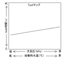
一方、ステップ102で二つの前提条件がともに成立している判定された場合には、ステップ104以降の点火時期遅角制御が実行される。まず、ステップ104では、始動時点火時期Aastが決定される。始動時点火時期Aastは、内燃機関10の始動時に設定する点火時期の設定値であり、アイドル時の通常点火時期(アイドル点火時期)Aopnよりも遅角側に設定されている。始動時点火時期Aastは、図3に示すようなマップにおいて始動時水温毎に、また、大気圧毎に定められており、ECU2は、水温センサ20で検出された水温と大気圧センサ22で検出された大気圧とに応じた始動時点火時期Aastをマップから読み込む。なお、大気圧はエアフローメータで検出される吸入空気量から求めることもできる。図3に示すマップでは、始動時点火時期Aastは大気圧が低いほど進角側に設定されている。これは空気密度と出力との関係が考慮されたものであり、空気密度の低下に伴う出力の低下が点火時期の遅角量の調整によって補償されている。また、始動時水温が低いほど始動時点火時期Aastは進角側に設定されているが、これは内燃機関10の摩擦損失が考慮されたものであり、低温時の摩擦損失による出力の低下が点火時期の遅角量の調整によって補償されている。
On the other hand, if it is determined in
さらに、ステップ104では、最大保持時間Tastも決定される。最大保持時間Tastは点火時期を始動時点火時期Aastに保持する最大時間を定めたものである。本発明にかかる点火時期遅角制御は、機関回転数の回転ピークまで点火時期を始動時点火時期Aastに保持することを特徴としているが、後述する回転ピークの検出処理において回転ピークを検出し損ねる可能性がないとは限らない。そこで、最大保持時間Tastを設定しておくことで、万が一、上記のような事態になった場合にでも点火時期遅角制御を必ず終了できるようにしている。最大保持時間Tastは、図4に示すようなマップにおいて始動時水温毎に、また、大気圧毎に定められており、ECU2は、水温センサ20で検出された水温と大気圧センサ22で検出された大気圧とに応じた最大保持時間Tastをマップから読み込む。図4に示すマップでは、最大保持時間Tastは大気圧が低いほど、また、始動時水温が低いほど短く設定されている。これは、出力が相対的に低い状況では、機関回転数が回転ピークに達するまでの時間も短くなることが考慮されたものである。なお、最大保持時間Tastはあくまでも非常用であるので、機関回転数が回転ピークに達する時間よりも十分に長く設定されている。
In
次のステップ106では、点火プラグ12の点火時期aopがステップ104で決定された始動時点火時期Aastに設定される。点火時期aopは、次のステップ108の判定が成立するまで始動時点火時期Aastに保持される。ステップ108では、まず、内燃機関10の完爆完了後であって機関回転数の変化率ΔNEが所定の閾値DLNEp(例えば5rpm)よりも小さくなったか否か判定される。内燃機関10の始動後、機関回転数は急激に上昇し、やがてその上昇速度は低下してそのうちゼロに至るので、回転数変化率ΔNEが閾値DLNEpよりも小さくなったときが回転ピークであると判断することができる。これにより、点火時期aopは機関回転数の回転ピークが検出されるまで始動時点火時期Aastに保持されることになる。なお、内燃機関10の完爆完了を判定するのは、スターターによる内燃機関10の駆動によって機関回転数が変動したときに誤って回転ピークが検出されてしまうことを防止するためである。
In the
ステップ108では、内燃機関10の始動からの経過時間が最大保持時間Tastを超えていないか否かについても判定される。これは前述のように回転ピークが検出されなかったときのための判定処理であり、通常は、始動後経過時間が最大保持時間Tastを超えるまでに回転数変化率ΔNEが閾値DLNEpを下回る。回転数変化率ΔNEが閾値DLNEpを下回るか、或いは、始動後経過時間が最大保持時間Tastを超えたときには、次のステップ110以降の処理によって点火時期aopの進角が行われる。
In
ステップ110では、機関回転数NEが目標アイドル回転数より所定値α以上低くなっていないか判定される。ここで用いられる機関回転数NEは、ステップ108の判定成立時の機関回転数、すなわち回転ピークにおける機関回転数である。通常、機関回転数は目標アイドル回転数を超えて吹き上がるが、燃料が重質燃料の場合には燃焼が良くなく、ステップ106及びステップ108の処理による回転上昇の抑制の結果、回転ピークにおける機関回転数NEが目標アイドル回転数に達しない可能性がある。このような場合には、内燃機関10がストールする可能性があるので、可能な限り速やかに点火時期aopを進角する必要がある。一方、回転ピークにおける機関回転数NEが目標アイドル回転数を超えている場合には、急激な出力の変動を招かないように回転ピーク後の機関回転数の低下に合わせて点火時期aopを進角するのが望ましい。
In
ステップ110で機関回転数NEが目標アイドル回転数より所定値α以上低いと判定された場合は、ステップ116に進み、点火時期遅角制御禁止フラグは1にセットされ、通常運転における点火時期制御が行われる。これにより、点火時期aopは通常の進角速度でアイドル時の通常点火時期aopnまで進角される。このときの進角速度は内燃機関10にノックが生じない限界の速度に設定されている。また、通常点火時期aopnは出力と燃料消費率が最良となるMBT(Minimum advance for the Best Torque)に設定されている。
If it is determined in
一方、ステップ110で機関回転数NEが目標アイドル回転数より所定値α低い回転数を上回っていると判定された場合は、ステップ112及びステップ114の処理によって点火時期aopが通常点火時期aopnまで進角されていく。まず、ステップ112では、現在の点火時期aopに所定のなまし量DLABUF1が加算された値が新たな点火時期aopとして設定される。ステップ114では、ステップ112で設定された点火時期aopが通常点火時期aopn以上になっているか否か判定される。そして、点火時期aopが通常点火時期aopn以上になるまで、ステップ112、ステップ114の処理が繰り返し実行される。これにより、点火時期aopは始動時点火時期Aastから通常点火時期aopnへ徐々に進角されていく。このときの進角速度は通常運転時における進角速度、つまり、ステップ110の判定でNoルートに進んだときの進角速度よりも低く設定されている。このように内燃機関10にノックが生じない限界の進角速度よりも遅い進角速度で点火時期aopが進角されることで、吸気管圧力の上昇に合わせた進角が可能になり、燃焼状態が安定して排気エミッションの悪化が防止される。
On the other hand, when it is determined in
ステップ114の判定で点火時期aopが通常点火時期aopn以上になった場合には、ステップ116に進み、点火時期遅角制御禁止フラグは1にセットされ、一連の点火時期遅角制御は終了される。点火時期遅角制御禁止フラグが1にセットされることで以降は通常運転における点火時期制御が行われることになる。これにより、その後に車両が発進する場合に誤って点火時期遅角制御が実行されることがなく、発進時のヘジテーションが防止される。その後、IGスイッチ26のオフやエンスト、或いはアイドルストップ制御などによって内燃機関10が停止したときには、点火時期遅角制御禁止フラグが0にリセットされるので、次回の始動時には再び上記のルーチンが実行される。
If it is determined in
図5は、図2のルーチンによる点火時期遅角制御が実行されたときの点火時期の時間変化を機関回転数、吸気管圧力、及び空燃比(A/F)の時間変化とともに示すグラフである。図5の各グラフにおいて、実線で示す変化は本点火時期遅角制御が実行されたときの変化を示し、破線で示す変化は本点火時期遅角制御が実行されないときの変化、すなわち、従来の点火時期制御(以下、従来制御という)が行われるときの変化を示している。 FIG. 5 is a graph showing the time change of the ignition timing when the ignition timing retarding control according to the routine of FIG. 2 is executed together with the time change of the engine speed, the intake pipe pressure, and the air-fuel ratio (A / F). . In each graph of FIG. 5, a change indicated by a solid line indicates a change when the ignition timing retardation control is executed, and a change indicated by a broken line indicates a change when the ignition timing retardation control is not executed, that is, a conventional change. A change when ignition timing control (hereinafter referred to as conventional control) is performed is shown.
図5に破線で示すように、従来制御では、内燃機関10が始動されると(時点t0)、その後直ぐに、点火時期は始動時点火時期Aastからアイドル時の通常点火時期aopnに向けて進角されていく。このときの進角速度は、通常、内燃機関10にノックが生じない限界の速度に設定されている。これに対し、点火時期遅角制御が実行される場合には、図5に実線で示すように内燃機関10の始動後も点火時期は始動時点火時期Aastに保持される。その結果、点火時期遅角制御時の機関回転数の上昇は従来制御時に比較して低く抑えられる。点火時期は機関回転数が回転ピークに達する時点(時点t1)まで始動時点火時期Aastに保持され続け、これにより、回転挙動の変化に左右されることなく、機関回転数が目標アイドル回転数を大きく超えて吹き上がることが防止される。回転ピーク後は、点火時期は始動時点火時期Aastからアイドル時の通常点火時期aopnに向けて進角されていくが、このときの進角速度は従来制御時の進角速度よりも低く設定されているので、機関回転数の再上昇は防止され、機関回転数は目標アイドル回転数に向けて滑らかに低下していく。
As indicated by a broken line in FIG. 5, in the conventional control, when the
このように機関回転数の過剰な吹き上がりが防止されることで、吸気管内に過大な負圧が作用することが防止される。内燃機関10の始動後、吸気管圧力は機関回転数の上昇に伴い低下していくが、従来制御時のように機関回転数がアイドル回転数を超えて過剰に吹き上がる場合には、吸気管内には過大な負圧が作用することになる。その結果、内燃機関10の吸気ポートに付着した燃料の気化が促進されて空燃比は一時的に大きくリッチ化する。ところが、回転ピーク後に機関回転数が低下し、吸気管圧力が上昇したときには、負圧の増大時に気化した燃料を補うように噴射燃料の多くが吸気ポートに付着し、空燃比は大きくリーン化してしまう。触媒が暖機されていない始動直後での空燃比のリーン化は排気エミッションの悪化を招くため、これを防止するためには始動時燃料を増量する必要が生じてしまう。これに対し、点火時期遅角制御の実行時には吸気管内に過大な負圧が作用することが防止されるので、吸気ポートの付着燃料の気化が抑制され、回転ピーク後に吸気管圧力が上昇したときの空燃比のリーン化が防止される。したがって、点火時期遅角制御を実行する場合には、リーン化防止のための始動時燃料の増量が不要になる。
By preventing the excessive increase in engine speed in this way, it is possible to prevent an excessive negative pressure from acting in the intake pipe. After the
以上のように、本実施形態の内燃機関の制御装置によれば、図2の点火時期遅角制御ルーチンが実行されることにより、回転挙動の変化に左右されることなく、機関回転数が過剰に吹き上がることも回転上昇が過剰に抑制されることも共に確実に防止することができる。また、機関回転数の過剰な吹き上がりが防止されることにより、空燃比の変動が抑制されるので、排気エミッションの悪化も防止することができる。 As described above, according to the control apparatus for an internal combustion engine of the present embodiment, the ignition timing retard control routine shown in FIG. Thus, it is possible to reliably prevent the air from being blown up and the increase in rotation being suppressed excessively. Further, since the excessive increase in the engine speed is prevented, fluctuations in the air-fuel ratio are suppressed, so that the exhaust emission can be prevented from deteriorating.
なお、上述した実施の形態においては、ECU2によるステップ108の処理の実行により、第1乃至第4の発明の「回転ピーク検出手段」が実現されている。また、ECU2によるステップ104乃至ステップ114の処理の実行により、第1乃至第4の発明の「回転上昇抑制手段」が実現され、さらに、ECU2によるステップ110の処理の実行により、第1及び第2の発明の「燃料性状判定手段」が実現されている。
In the above-described embodiment, the “rotation peak detecting means” of the first to fourth inventions is realized by the execution of the processing of
実施の形態2.
以下、図6乃至図8を参照して、本発明の実施の形態2について説明する。
図6は本発明の実施の形態2である内燃機関の制御装置の構成を示すブロック図である。図6中、上述の実施の形態1と共通する部位については、同一の符号を付し、それらについての重複する説明は省略するものとする。
The second embodiment of the present invention will be described below with reference to FIGS.
FIG. 6 is a block diagram showing the configuration of the control apparatus for an internal combustion engine according to the second embodiment of the present invention. In FIG. 6, parts that are the same as those in the first embodiment are given the same reference numerals, and redundant descriptions thereof are omitted.
本実施形態は、動力として内燃機関10とモータジェネレータ(以下、単にモータという)40とを並列に備えるハイブリッド車両(パラレル式のハイブリッド車両)を前提としている。モータ40は図示しないバッテリから電力の供給を受けることで電動機として機能し、内燃機関10から駆動力の供給を受けることで発電機として機能する。本実施形態では、内燃機関10の始動時にモータ40を発電機として機能させ、その発電負荷をECU2により制御することで、内燃機関10の始動直後における機関回転数の急激な上昇を抑制する。つまり、実施の形態1では、内燃機関10の出力を制御することで間接的に機関回転数を制御していたのに対し、本実施形態では内燃機関10に作用する負荷を制御することで間接的に機関回転数を制御するものである。
The present embodiment is premised on a hybrid vehicle (parallel type hybrid vehicle) including an
図7は本実施形態において内燃機関10の始動時にECU2が実施する回転上昇抑制制御の内容をフローチャートで示したものである。本実施形態における回転上昇抑制制御の概要は、機関回転数が回転ピークに達するまでの機関回転数の上昇期間はモータ負荷を通常モータ負荷よりも増大させ、機関回転数が回転ピークを超えた以降はモータ負荷を通常モータ負荷まで低下させていくというものである。このように内燃機関10に作用するモータ負荷を増大制御することで、点火時期遅角制御により出力を低下させる場合と同様の機関回転数の上昇抑制効果が得られる。以下、本実施形態における回転上昇抑制制御を特にモータ負荷増大制御という。
FIG. 7 is a flowchart showing the contents of the rotation increase suppression control performed by the
ECU2によるモータ負荷増大制御は、具体的には、図7のフローチャートに示すルーチン(負荷増大制御ルーチン)によって実行される。先ず、ステップ200では、内燃機関10が始動直後か否か判定される。始動直後か否かはモータ負荷増大制御禁止フラグが1か0かで判定される。モータ負荷増大制御禁止フラグは、モータ負荷増大制御の開始後、モータ負荷増大制御が終了することで1にセットされる。そして、内燃機関10が停止することで0にリセットされる。ECU2は、モータ負荷増大制御禁止フラグがリセットされている場合に、内燃機関10が始動直後であると判定する。
Specifically, the motor load increase control by the
ステップ200で内燃機関10が始動直後でないと判定された場合は、ステップ216に進み、モータ負荷増大制御禁止フラグは1にセットされ、通常運転におけるモータ負荷制御が行われる。
When it is determined in
一方、ステップ200で内燃機関10が始動直後であると判定された場合には、ステップ202においてモータ負荷増大制御を実行するための二つの前提条件が成立しているか否か判定される。前提条件の内容は、実施の形態1の点火時期遅角制御にかかるステップ102の前提条件(第1前提条件及び第2前提条件)と同内容であるので、その説明は省略する。
On the other hand, if it is determined in
ステップ202で何れかの前提条件が不成立と判定された場合には、ステップ216に進み、モータ負荷増大制御禁止フラグは1にセットされ、通常運転におけるモータ負荷制御が行われる。
If it is determined in
一方、ステップ202で二つの前提条件がともに成立していると判定された場合には、ステップ204以降のモータ負荷増大制御が実行される。まず、ステップ204では、モータ負荷の負荷増加量Lastが決定される。負荷増加量Lastは、内燃機関10の始動時にアイドル時の通常モータ負荷(アイドル時負荷)に加算される負荷量である。負荷増加量Lastは、図8に示すようなマップにおいて始動時水温毎に、また、大気圧毎に定められており、ECU2は、水温センサ20で検出された水温と大気圧センサ22で検出された大気圧とに応じた負荷増加量Lastをマップから読み込む。図8に示すマップでは、負荷増加量Lastは大気圧が低いほど小さく設定されている。これは空気密度と出力との関係が考慮されたものであり、空気密度の低下に伴う出力の低下がモータ負荷の調整によって補償されている。また、始動時水温が低いほど負荷増加量Lastは小さく設定されているが、これは内燃機関10の摩擦損失が考慮されたものであり、低温時の摩擦損失による出力の低下がモータ負荷の調整によって補償されている。
On the other hand, when it is determined in
さらに、ステップ204では、最大保持時間Tastも決定される。最大保持時間Tastは通常モータ負荷に負荷増加量Lastを加算し続ける最大時間を定めたものである。最大保持時間Tastを定める理由及びその決定方法については、実施の形態1の点火時期遅角制御の場合と同じであるので、その説明は省略する。
In
次のステップ206では、機関回転数NEが所定回転数Neastを超えている否か判定される。これは、モータ負荷の増大による内燃機関10のストールを防止するための処理であり、機関回転数NEが所定回転数Neastを超えるまではステップ206の判定が繰り返し行われる。
In the
そして、ステップ206で機関回転数NEが所定回転数Neastを超えたと判定された場合には、ステップ208に進み、モータ負荷にステップ204で決定された負荷増加量Lastが加算される。モータ負荷は次のステップ210の判定が成立するまで負荷増加量Lastが加算された値に保持される。ステップ210における判定の内容については、実施の形態1の点火時期遅角制御にかかるステップ108の判定内容と同じであり、回転数変化率ΔNEが閾値DLNEpを下回るか、或いは、始動後経過時間が最大保持時間Tastを超えたときに判定が成立する。このように、回転数変化率ΔNEが閾値DLNEpを下回るまで、つまり、機関回転数が回転ピークに達するまでモータ負荷に負荷増加量Lastが加算されることで、回転挙動の変化に左右されることなく、機関回転数が目標アイドル回転数を大きく超えて吹き上がることが防止される。
If it is determined in
ステップ210における判定の結果、回転数変化率ΔNEが閾値DLNEpを下回るか、或いは、始動後経過時間が最大保持時間Tastを超えたときには、次のステップ212及びステップ214の処理によってモータ負荷が通常モータ負荷まで低下されていく。まず、ステップ212では、現在の負荷増加量Lastから所定のなまし量DLLAST1が減算された値が新たな負荷増加量Lastとして設定される。ステップ214では、現在のモータ負荷が通常モータ負荷以下になっているか否か判定され、モータ負荷が通常モータ負荷以下になるまで、ステップ212、ステップ214の処理が繰り返し実行される。これにより、モータ負荷は通常モータ負荷まで徐々に減衰していく。このようにモータ負荷を徐々に減衰させることで、機関回転数の再上昇を防止して機関回転数を滑らかに低下させていくことが可能になる。
As a result of the determination in
ステップ214の判定でモータ負荷が通常モータ負荷以下になった場合には、ステップ216に進み、モータ負荷増大制御禁止フラグは1にセットされ、一連のモータ負荷増大制御は終了される。モータ負荷増大制御禁止フラグが1にセットされることで以降は通常運転におけるモータ負荷制御が行われることになる。これにより、その後に車両が発進する場合に誤ってモータ負荷増大制御が実行されることがなく、発進時のヘジテーションが防止される。その後、IGスイッチ26のオフやエンスト、或いはアイドルストップ制御などによって内燃機関10が停止したときには、モータ負荷増大制御禁止フラグが0にリセットされるので、次回の始動時には再び上記のルーチンが実行される。
If it is determined in
以上のように、本実施形態の内燃機関の制御装置によれば、図7のモータ負荷増大制御ルーチンが実行されることにより、回転挙動の変化に左右されることなく、機関回転数が過剰に吹き上がることも回転上昇が過剰に抑制されることも共に確実に防止することができる。また、実施の形態1の点火時期遅角制御と同様、機関回転数の過剰な吹き上がりが防止されることにより空燃比の変動を抑制することができ、排気エミッションの悪化も防止することができる。さらに、本実施形態の内燃機関の制御装置によれば、従来制御では無駄な回転上昇に用いられていたエネルギを電力として回生できるという利点もある。 As described above, according to the control apparatus for an internal combustion engine of the present embodiment, the motor load increase control routine in FIG. Both blowing up and excessive increase in rotational speed can be reliably prevented. Further, similarly to the ignition timing retarding control of the first embodiment, the excessive increase in the engine speed can be prevented, so that the fluctuation of the air-fuel ratio can be suppressed and the exhaust emission can be prevented from deteriorating. . Furthermore, according to the control apparatus for an internal combustion engine of the present embodiment, there is an advantage that the energy used for the unnecessary rotation increase in the conventional control can be regenerated as electric power.
その他.
以上、本発明の実施の形態について説明したが、本発明は上述の実施の形態に限定されるものではなく、本発明の趣旨を逸脱しない範囲で種々変形して実施することができる。例えば次のように変形して実施してもよい。
Others.
Although the embodiments of the present invention have been described above, the present invention is not limited to the above-described embodiments, and various modifications can be made without departing from the spirit of the present invention. For example, the following modifications may be made.
実施の形態1では、機関回転数の制御するための手段として点火時期を調整しているが、内燃機関10の出力に係わる制御パラメータであれば、燃料噴射量などの他の制御パラメータを調整してもよい。ただし、吸入空気量を制御パラメータとして用いると、内燃機関10の出力を抑制するためにはISCバルブ18のバルブ開度を絞ることになってしまい、吸気管内の負圧を増大させてしまう。吸気管内の負圧の増大はその後の空燃のオーバーリーンを招くために好ましくない。したがって、点火時期以外の制御パラメータを用いる場合には、吸入空気量とは異なる制御パラメータを用いるのが望ましい。
In the first embodiment, the ignition timing is adjusted as a means for controlling the engine speed. However, if the control parameter is related to the output of the
また、実施の形態2ではハイブリッド車両を前提とし、モータ40のモータ負荷を調整しているが、内燃機関10により駆動される機器の負荷であれば、他の機器の負荷を調整するようにしてもよい。例えば、オルタネータの負荷やエアコンの負荷を調整するようにしてもよい。
In the second embodiment, the motor load of the
2 ECU
10 内燃機関
12 点火プラグ
14 インジェクタ
16 スロットルバルブ
18 ISCバルブ
20 水温センサ
22 大気圧センサ
24 回転数センサ
26 IGスイッチ
28 アイドルスイッチ
30 シフトポジションスイッチ
40 モータジェネレータ
2 ECU
DESCRIPTION OF
Claims (4)
前記内燃機関の点火時期を調整することで機関回転数の上昇を抑制する回転上昇抑制手段と、
前記内燃機関に供給される燃料の性状を判定する燃料性状判定手段とを備え、
前記回転上昇抑制手段は、前記内燃機関の始動後、前記回転ピーク検出手段により回転ピークが検出されるまで点火時期をアイドル点火時期より遅角側に設定された始動時点火時期に保持し、回転ピークの検出後に点火時期を前記始動時点火時期から前記アイドル点火時期まで進角させ、前記燃料性状判定手段により燃料性状が重質であると判定された場合には、軽質であると判定された場合よりも回転ピーク検出後の点火時期の進角速度を大きく設定することを特徴とする内燃機関の制御装置。 A rotation peak detecting means for detecting a rotation peak of the engine speed after starting the internal combustion engine;
A rotation increase suppressing means for suppressing an increase in engine speed by adjusting the ignition timing of the internal combustion engine ;
Fuel property determining means for determining the property of the fuel supplied to the internal combustion engine ,
The rotation rise suppression means holds the ignition timing at the start timing ignition timing set to the retard side from the idle ignition timing until the rotation peak is detected by the rotation peak detection means after the internal combustion engine is started , After the detection of the peak, the ignition timing is advanced from the starting ignition timing to the idle ignition timing, and when the fuel property determining means determines that the fuel property is heavy, it is determined to be light. A control device for an internal combustion engine, characterized in that the advance speed of the ignition timing after detection of the rotation peak is set larger than the case .
前記内燃機関の点火時期を調整することで機関回転数の上昇を抑制する回転上昇抑制手段とを備え、A rotation increase suppression means for suppressing an increase in engine speed by adjusting the ignition timing of the internal combustion engine;
前記回転上昇抑制手段は、前記内燃機関の始動後、前記回転ピーク検出手段により回転ピークが検出されるまで点火時期をアイドル点火時期より遅角側に設定された始動時点火時期に保持し、回転ピークの検出後は、回転ピーク検出時の機関回転数に応じて点火時期の進角速度を設定し、設定した進角速度にて前記始動時点火時期から前記アイドル点火時期まで点火時期を進角させることを特徴とする内燃機関の制御装置。The rotation rise suppression means holds the ignition timing at the start timing ignition timing set to the retard side from the idle ignition timing until the rotation peak is detected by the rotation peak detection means after the internal combustion engine is started, After the detection of the peak, the advance speed of the ignition timing is set according to the engine speed at the time of detection of the rotation peak, and the ignition timing is advanced from the start ignition timing to the idle ignition timing at the set advance speed. A control device for an internal combustion engine.
Priority Applications (3)
| Application Number | Priority Date | Filing Date | Title |
|---|---|---|---|
| JP2004000114A JP4100343B2 (en) | 2004-01-05 | 2004-01-05 | Control device for internal combustion engine |
| US11/020,119 US7032571B2 (en) | 2004-01-05 | 2004-12-27 | Internal combustion engine controller |
| DE102005000741.4A DE102005000741B4 (en) | 2004-01-05 | 2005-01-04 | Engine control means |
Applications Claiming Priority (1)
| Application Number | Priority Date | Filing Date | Title |
|---|---|---|---|
| JP2004000114A JP4100343B2 (en) | 2004-01-05 | 2004-01-05 | Control device for internal combustion engine |
Publications (2)
| Publication Number | Publication Date |
|---|---|
| JP2005194902A JP2005194902A (en) | 2005-07-21 |
| JP4100343B2 true JP4100343B2 (en) | 2008-06-11 |
Family
ID=34708956
Family Applications (1)
| Application Number | Title | Priority Date | Filing Date |
|---|---|---|---|
| JP2004000114A Expired - Lifetime JP4100343B2 (en) | 2004-01-05 | 2004-01-05 | Control device for internal combustion engine |
Country Status (3)
| Country | Link |
|---|---|
| US (1) | US7032571B2 (en) |
| JP (1) | JP4100343B2 (en) |
| DE (1) | DE102005000741B4 (en) |
Cited By (1)
| Publication number | Priority date | Publication date | Assignee | Title |
|---|---|---|---|---|
| US8422361B2 (en) | 2007-01-15 | 2013-04-16 | Fujitsu Limited | Management of protection path bandwidth and changing of path bandwidth |
Families Citing this family (18)
| Publication number | Priority date | Publication date | Assignee | Title |
|---|---|---|---|---|
| JP2008025503A (en) * | 2006-07-24 | 2008-02-07 | Toyota Motor Corp | Start control device for internal combustion engine |
| JP4100443B2 (en) * | 2006-10-25 | 2008-06-11 | トヨタ自動車株式会社 | Control device for hybrid vehicle |
| US7948355B2 (en) * | 2007-05-24 | 2011-05-24 | Industrial Technology Research Institute | Embedded resistor devices |
| US20080314349A1 (en) * | 2007-06-25 | 2008-12-25 | Robert Bosch Gmbh | Green start engine control systems and methods |
| US8020652B2 (en) | 2007-12-04 | 2011-09-20 | Ford Global Technologies, Llc | Generator power-based cold start strategy |
| US8261864B2 (en) * | 2008-06-17 | 2012-09-11 | GM Global Technology Operations LLC | Hybrid powertrain auto start control system with engine pulse cancellation |
| JP2010138795A (en) * | 2008-12-11 | 2010-06-24 | Toyota Motor Corp | Internal combustion engine control device |
| JP5031784B2 (en) | 2009-03-02 | 2012-09-26 | 日立オートモティブシステムズ株式会社 | Control device for internal combustion engine |
| JP5236608B2 (en) * | 2009-09-25 | 2013-07-17 | 富士通テン株式会社 | Idling stop device and disabling method of idling stop function |
| US8464529B2 (en) * | 2011-03-02 | 2013-06-18 | Ford Global Technologies, Llc | Reduction in turbocharger lag at high altitudes |
| CN103764466A (en) * | 2011-08-31 | 2014-04-30 | 丰田自动车株式会社 | Hybrid vehicle and hybrid vehicle control method |
| KR101339233B1 (en) * | 2011-12-01 | 2013-12-09 | 기아자동차 주식회사 | System and method for determining stop status of hev engine |
| JP5957995B2 (en) * | 2012-03-19 | 2016-07-27 | マツダ株式会社 | Engine start control device |
| DE102012112948A1 (en) * | 2012-12-21 | 2014-06-26 | Makita Corp. | Method and device for controlling the operation of an internal combustion engine |
| JP6549861B2 (en) * | 2015-03-10 | 2019-07-24 | 株式会社Subaru | Automobile |
| DE102017218721B4 (en) | 2017-10-19 | 2020-12-10 | Audi Ag | Method for providing heating power for heating up an internal combustion engine and a motor vehicle that can be operated according to the method |
| WO2019187428A1 (en) * | 2018-03-30 | 2019-10-03 | 本田技研工業株式会社 | Engine control device |
| GB2642508A (en) * | 2024-07-11 | 2026-01-14 | Jaguar Land Rover Ltd | Air control signal for a powertrain of a vehicle |
Family Cites Families (9)
| Publication number | Priority date | Publication date | Assignee | Title |
|---|---|---|---|---|
| US4719794A (en) * | 1986-05-01 | 1988-01-19 | General Motors Corporation | System and method of engine calibration |
| DE4329448B4 (en) * | 1993-09-01 | 2007-08-23 | Robert Bosch Gmbh | Method and device for metering fuel in the starting case of an internal combustion engine |
| US5855533A (en) * | 1996-12-09 | 1999-01-05 | General Motors Corporation | Automotive powertrain control |
| DE19939821B4 (en) * | 1999-08-21 | 2009-08-20 | Robert Bosch Gmbh | Method and device for controlling the speed of an internal combustion engine |
| JP2001304084A (en) | 2000-04-28 | 2001-10-31 | Toyota Motor Corp | Vehicle control method and vehicle control device |
| DE10047502A1 (en) * | 2000-09-26 | 2002-04-11 | Bosch Gmbh Robert | Controlling drive unit revolution rate for starter motor of an IC engine, involves controlling electrical machine applying torque to engine depending on deviation between demand and actual revolution rates in starting phase |
| JP3959956B2 (en) | 2000-11-30 | 2007-08-15 | スズキ株式会社 | Ignition timing control device for internal combustion engine |
| JP2002266689A (en) | 2001-03-09 | 2002-09-18 | Mitsubishi Automob Eng Co Ltd | Control device for internal combustion engine |
| DE10141929A1 (en) * | 2001-08-28 | 2003-03-27 | Volkswagen Ag | Procedure for starting a gasoline engine |
-
2004
- 2004-01-05 JP JP2004000114A patent/JP4100343B2/en not_active Expired - Lifetime
- 2004-12-27 US US11/020,119 patent/US7032571B2/en not_active Expired - Lifetime
-
2005
- 2005-01-04 DE DE102005000741.4A patent/DE102005000741B4/en not_active Expired - Lifetime
Cited By (1)
| Publication number | Priority date | Publication date | Assignee | Title |
|---|---|---|---|---|
| US8422361B2 (en) | 2007-01-15 | 2013-04-16 | Fujitsu Limited | Management of protection path bandwidth and changing of path bandwidth |
Also Published As
| Publication number | Publication date |
|---|---|
| DE102005000741A1 (en) | 2005-09-01 |
| JP2005194902A (en) | 2005-07-21 |
| US20050145217A1 (en) | 2005-07-07 |
| US7032571B2 (en) | 2006-04-25 |
| DE102005000741B4 (en) | 2016-08-18 |
Similar Documents
| Publication | Publication Date | Title |
|---|---|---|
| JP4100343B2 (en) | Control device for internal combustion engine | |
| JP4678442B2 (en) | Vehicle control device | |
| JP4110910B2 (en) | Throttle opening control device for internal combustion engine | |
| US8251042B2 (en) | Control unit and control method for torque-demand-type internal combustion engine | |
| US7975670B2 (en) | Control unit and control method for torque-demand-type internal combustion engine | |
| EP2199579B1 (en) | Controller of internal combustion engine | |
| EP2213870B1 (en) | Startup Control Apparatus And Method For Internal Combustion Engine | |
| JP5063380B2 (en) | Control method for internal combustion engine | |
| JP2016098786A (en) | Internal combustion engine control device | |
| JP2012052468A (en) | Engine control device | |
| JP2009036036A (en) | Ignition timing control device for internal combustion engine | |
| JP6367497B2 (en) | VEHICLE CONTROL DEVICE, VEHICLE CONTROL SYSTEM, AND CONTROL METHOD FOR VEHICLE CONTROL DEVICE | |
| JP2008190428A (en) | Control device for internal combustion engine | |
| JP4458019B2 (en) | Control device for vehicle engine | |
| JP4289110B2 (en) | Control device for internal combustion engine | |
| JP4923797B2 (en) | Vehicle control device | |
| JP5573745B2 (en) | Engine control device | |
| JP2008298032A (en) | Ignition timing control device for internal combustion engine | |
| JP2012112323A (en) | Control device of spark ignition type internal combustion engine | |
| JP2010065640A (en) | Control device for internal combustion engine | |
| JP2008267329A (en) | Idle rotational speed control device for vehicle engine | |
| JP2000345899A (en) | Throttle control device for internal combustion engine | |
| JP3991685B2 (en) | Fuel injection control device for internal combustion engine | |
| JP4660493B2 (en) | Electric throttle device | |
| JP2015010590A (en) | Control device and control method for internal combustion engine |
Legal Events
| Date | Code | Title | Description |
|---|---|---|---|
| A621 | Written request for application examination |
Free format text: JAPANESE INTERMEDIATE CODE: A621 Effective date: 20050420 |
|
| A131 | Notification of reasons for refusal |
Free format text: JAPANESE INTERMEDIATE CODE: A131 Effective date: 20070814 |
|
| RD02 | Notification of acceptance of power of attorney |
Free format text: JAPANESE INTERMEDIATE CODE: A7422 Effective date: 20071012 |
|
| A131 | Notification of reasons for refusal |
Free format text: JAPANESE INTERMEDIATE CODE: A131 Effective date: 20071127 |
|
| A521 | Request for written amendment filed |
Free format text: JAPANESE INTERMEDIATE CODE: A523 Effective date: 20080125 |
|
| TRDD | Decision of grant or rejection written | ||
| A01 | Written decision to grant a patent or to grant a registration (utility model) |
Free format text: JAPANESE INTERMEDIATE CODE: A01 Effective date: 20080226 |
|
| A61 | First payment of annual fees (during grant procedure) |
Free format text: JAPANESE INTERMEDIATE CODE: A61 Effective date: 20080310 |
|
| FPAY | Renewal fee payment (event date is renewal date of database) |
Free format text: PAYMENT UNTIL: 20110328 Year of fee payment: 3 |
|
| R151 | Written notification of patent or utility model registration |
Ref document number: 4100343 Country of ref document: JP Free format text: JAPANESE INTERMEDIATE CODE: R151 |
|
| FPAY | Renewal fee payment (event date is renewal date of database) |
Free format text: PAYMENT UNTIL: 20110328 Year of fee payment: 3 |
|
| FPAY | Renewal fee payment (event date is renewal date of database) |
Free format text: PAYMENT UNTIL: 20120328 Year of fee payment: 4 |
|
| FPAY | Renewal fee payment (event date is renewal date of database) |
Free format text: PAYMENT UNTIL: 20120328 Year of fee payment: 4 |
|
| FPAY | Renewal fee payment (event date is renewal date of database) |
Free format text: PAYMENT UNTIL: 20130328 Year of fee payment: 5 |
|
| FPAY | Renewal fee payment (event date is renewal date of database) |
Free format text: PAYMENT UNTIL: 20130328 Year of fee payment: 5 |
|
| FPAY | Renewal fee payment (event date is renewal date of database) |
Free format text: PAYMENT UNTIL: 20140328 Year of fee payment: 6 |
|
| EXPY | Cancellation because of completion of term |