JP4088678B2 - Electric power steering device - Google Patents
Electric power steering device Download PDFInfo
- Publication number
- JP4088678B2 JP4088678B2 JP2002110441A JP2002110441A JP4088678B2 JP 4088678 B2 JP4088678 B2 JP 4088678B2 JP 2002110441 A JP2002110441 A JP 2002110441A JP 2002110441 A JP2002110441 A JP 2002110441A JP 4088678 B2 JP4088678 B2 JP 4088678B2
- Authority
- JP
- Japan
- Prior art keywords
- steering
- slip angle
- differential value
- vehicle speed
- electric power
- Prior art date
- Legal status (The legal status is an assumption and is not a legal conclusion. Google has not performed a legal analysis and makes no representation as to the accuracy of the status listed.)
- Expired - Fee Related
Links
Images


Landscapes
- Power Steering Mechanism (AREA)
- Steering Control In Accordance With Driving Conditions (AREA)
Description
【0001】
【発明の属する技術分野】
この発明は、モータにより操舵をアシストする電気式動力舵取装置に関するものである。
【0002】
【従来の技術】
電気式動力舵取装置として、ステアリングホイールが固定された入力軸に、操舵トルクを検出するトルクセンサを取り付け、トルクセンサで検出した操舵トルクに応じたアシストトルクを電動モータにより発生させ操舵力を軽減するものが一般的に知られている。係る電気式動力舵取装置では、車速を検出して、操舵トルクに応じたアシストトルクを調整している。
【0003】
現在、電気式動力舵取装置で操舵アシストを行うだけではなく、アシスト量を積極的に調整することで、車両の走行性能を向上させる技術が種々提案されている。例えば、特開2000−238654号では、車両の目標スリップ角、スリップ角微分の値を用いて車両の走行性能を向上させる技術が提案されている。この技術では、横加速度センサ、車速センサ、ヨーレートセンサを使い、車両のスリップ状態の指標となるスリップ角微分値を推定し、予め定められた限界値を超える際には、旋回限界でありスリップが開始すると判定してアシスト量を低減することで操舵を重くする。または、横加速度(またはスリップ角微分値)の符号を反対にしアシストトルクに加えることで、操舵反力の位相を進めて高速走行時の安定性を確保する。
【0004】
【発明が解決しようとする課題】
しかしながら、スリップ角微分値が予め定められた限界値を超える際に舵を重くする方法では、高速のレーンチェンジの際、急操舵等の限界を超えない領域では、スリップ角微分値が限界値を越えないため、操舵を重くする制御が働かず、収斂性、安定性が高まらない。一方、横加速度の符号を反転して用いる方法では、車両重量、車速を考慮していないため、車両重量の重い車両で、高速走行した際の収斂性、安定性が高まらない。また、低速で穏やかに操舵した場合でもスリップ角微分値が高くなると、アシスト量が減り操舵が重くなるという不都合がある。
【0005】
本発明は、上述した課題を解決するためになされたものであり、その目的とするところは、高速レーンチェンジの際の収斂性を高め得る電気式動力舵取装置を提供することにある。
【0008】
【課題を解決するための手段】
請求項1の発明では、操舵状態を検出し、操舵状態に応じてモータを駆動して操舵方向へアシストするアシスト制御部を備える電気式動力舵取装置において、 スリップ角微分値を演算するスリップ角微分値演算手段と、
演算されたスリップ角微分値と車速及び車両重量に基づき、前記アシスト制御部によるアシスト量を低減させるスリップ角補償制御手段とを有することを技術的特徴とする。
【0009】
請求項1の電気式動力舵取装置では、演算されたスリップ角微分値と車速及び車両重量に基づきアシスト量を低減させる。このため、スリップ角微分値があまり大きくならない高速レーンチェンジにおいても、スリップ角微分値、即ち、スリップ角の急変を押さえるようにスリップ角微分値、車速及び車両重量(車両慣性)に応じて操舵を重くするため、収斂性、安定性を高めることができる。
【0010】
請求項2では、スリップ角補償制御手段が、スリップ角微分値が所定範囲の中立不感帯値より小さいときに、アシスト制御部によるアシスト量を低減させないため、意図しないアシストトルクに変化による操舵フィーリングの劣化を防ぐことができる。
【0011】
請求項3では、前記スリップ角補償制御手段は、車速が所定のしきい値よりも低いときに、前記アシスト制御部によるアシスト量を低減させない。即ち、演算によりスリップ角微分値を正確に求められない低速時に制御を行わないことで、操舵フィーリングの劣化を防ぐ。
【0012】
請求項4の電気式動力舵取装置では、路面μを考慮してスリップ角微分値を演算するため、雨天等の路面μが低下している際には、スリップ角微分値が晴天時の路面μと比べて大きな値となる。これにより、低μ路での収斂性を高めることができる。
【0013】
請求項5の電気式動力舵取装置では、制動力及び駆動力を考慮してスリップ角微分値を演算する。制動力、駆動力でも前後輪での垂直荷重が変化し、ヨーレート、スリップ角、スリップ角微分値が変化するため、制動力及び駆動力を考慮することで、旋回中における制動力、駆動力の状態変化を補正することができる。
【0014】
請求項6の発明は、ステアリングホイールと操舵輪とを連結する操舵伝達系の途中に電動モータの駆動により伝達比を可変する伝達比可変手段を備えた電気式動力舵取装置であって、
前記ステアリングホイールから前記伝達比可変手段に入力される操舵角を検出して操舵角信号を出力する操舵角センサと、
スリップ角微分値を演算するスリップ角微分値演算手段と、
車両速度を検出して車速信号を出力する速度センサと、
前記車速信号と前記操舵角信号とに基づくと共に、前記スリップ角微分値が所定値を越えないように前記電動モータの回転角を決定する回転角決定手段と、
を備えることを技術的特徴とする。
【0015】
請求項6では、スリップ角微分値が所定値を越えないように電動モータの回転角を決定し、ステアリングホイールと操舵輪との伝達比を調整するため、スリップ角微分値が所定値を越えないよう操舵輪を制御し、車両のスリップを未然に防ぐことができる。
【0018】
【発明の実施の形態】
以下、本発明の実施形態に係る電気式動力舵取装置について図を参照して説明する。
[第1実施形態]
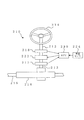
図1は第1実施態様の電気式動力舵取装置10の構成を示すブロック図である。電気式動力舵取装置10は、操舵トルクを検出するためのトルクセンサ22と、トルクセンサ22からの操舵トルク及び車速センサ24からの車速に基づきモータ指令トルク(操舵アシスト量)を演算する制御装置30と、モータ指令トルクに応じた電流指令値を求めてモータMへの通電を制御するモータ駆動回路26とを備える。
【0019】
トルクセンサ22は、車両の操舵ステアリング14に連結された入力軸12に配設されている。モータMの出力は、減速機16により減速され、前輪を操舵するためのラック・ピニオンギア18に伝達される。
【0020】
制御装置30及びモータ駆動回路26の制御系について、図2のブロック図に示す。トルクセンサ22からの出力(操舵トルク:電圧値)は、A/D変換32を介してデジタル値に変換され、トルク演算34にてトルク値が演算される。演算されたトルク値は、ローパスフィルタ36にてノイズが除去され、加算ノード38を介してアシスト制御60へ入力される。一方、車速センサ24からの車速(パルス信号)は、I/F40を介して車速演算42に入力され、演算された車速がアシスト制御60へ入力される。一方、ローパスフィルタ36からの出力は、微分44を介して、位相補償46にて位相補償され、加算ノード38を介してアシスト制御60へ入力される。該位相補償46は、操舵トルク値を微分44にて微分することで位相を進め、操舵アシストの遅れを補償する。即ち、検出値に基づき指令値を演算すると、演算完了までに一定の時間がかかり、この一定時間が、検出値に対する指令値の遅れとなって、現在の検出値に基づいて指令値を求めると、操舵アシストを適正に制御し得ない。このため、該位相補償46が操舵トルクの位相を進める。
【0021】
アシスト制御60の内容を図3(B)に示す。加算ノード38からの操舵トルクに応じて、アシストマップ62により、指令トルク値が決定される。即ち、操舵トルクが大きいときには、高い指令トルク値が決定され、操舵トルクが小さいときには、低い指令トルク値が決定され、乗算ノード68側へ出力される。また、第1実施形態の電気式動力舵取装置においては、操舵トルクが所定値よりも小さいときには、該操舵トルクに応じたモータ制御を行わないようにする「不感帯」を設けてある。即ち、不感帯を設けることで、中、高速走行時のステアリング中立付近での剛性感を高め、操舵フィーリングを高めている。操舵トルクTsよりも小さな操舵トルクのときは、指令トルクが0として出力される。また、所定の操舵トルクTmよりも大きいときには、最大値として一定の指令トルク値(モータの最大出力)が出力される。
【0022】
車速センサ24からの車速値は、車速ゲインマップ64により車速に応じた重み付けが行われる。車速に応じて車速ゲインマップを検索することで、例えば、車速0km/hの際には“1”を出力し、100km/hの際には“0.2”を出力する。これにより、操舵アシスト量を車速に応じて重み付けを行うことでステアリングを操作する際、低速時に操舵を軽く、反対に、高速時に操舵を重くしている。車速ゲインマップ64からの車速重み付け値が乗算ノード68側へ出力され、上述した指令トルクが車速に応じて補正される。
【0023】
図2に示すように、アシスト制御60からの指令トルク値は、加算ノード48を介して電流指令リミッタ50に加えられる。電流指令リミッタ50では、モータMの最大出力を越える指令トルク値が制限される。
【0024】
電流指令リミッタ50からの指令トルク値は、減算ノード52を介してPI制御100に加えられる。PI制御100の内容を図5に示す。PI制御100では、指令トルク値にGpゲインが加えられ、加算ノード102に印加され、また、指令トルク値が微分されGiゲインが加えられ、加算ノード102へ印加される。一方、上記減算ノード52へは、ローパスフィルタ112及びA/D変換114を介してモータMの電流が印加される。PI制御100では、A/D変換114を介して入力された実モータ電流が、指令トルク値(指令電流値)となるようにPIフィードバック制御が行われる。
【0025】
PI制御100からの指令トルク値は、モータ駆動回路26へ印加される。モータ駆動回路26のPWM演算27は、指令トルク値に応じた出力をモータMに発生させるようにトランジスタTr1、Tr2、Tr3,Tr4のベースに電流を印加し、PWM制御を行う。
【0026】
モータU相の電位は、ローパスフィルタ122及びA/D変換124を介して差動アンプ136の非反転入力に加えられる。モータV相の電位は、ローパスフィルタ132及びA/D変換134を介して差動アンプ136の反転入力に加えられる。差動アンプ136からモータ端子間電圧が出力され、減算ノード54へ印加される。上述したA/D変換114を介して入力されたモータ電流が、(LS+R)138で乗算されてモータ起電力として減算ノード54へ印加され、減算ノード54からモータの逆起電力が出力される。ここで、乗算される(LS+R)中のLSは、モータインダクタンスの微分値を、Rは、モータの抵抗分を示している。
【0027】
減算ノード54からの逆起電力は、アンプ56にて逆起電力定数Keが除算され、モータの角速度が求められ、更に、アンプ58にて減速機16の減速比Giが除算されて、ハンドルの角速度ωとして、ハンドル戻し補償制御80、ダンパ補償制御90及び停止時ダンパ制御140へ印加される。ここでは、ハンドルの角速度ωを演算により推測しているが、舵角センサにより角速度を検出することも可能である。
【0028】
ハンドル戻し補償制御80は、低速において路面の反力による舵の戻りがモータMと減速機16の摩擦抵抗により遅くなる電気式動力舵取装置の特性を補償するための制御を行う。ハンドル戻し補償制御80の内容を図4(A)に示す。ハンドルの角速度に応じて、ハンドル戻しマップ82により、ハンドル戻し量が決定される。即ち、ハンドルの角速度が大きいときには、大きなハンドルの戻り量が決定され、角速度が小さいときには、小さなハンドルの戻り量が決定され、乗算ノード88側へ出力される。第1実施形態の電気式動力舵取装置のハンドル戻しマップ82においては、上述したアシストマップ62と同様に、角速度が所定値よりも小さいときには、角速度に応じたモータ制御を行わないようにする「不感帯」を設けてある。また、また、所定の角速度よりも大きいときには、最大値として一定のハンドルの戻り量が出力される。
【0029】
車速センサ24からの車速値は、車速ゲインマップ84により車速に応じた重み付けが行われる。車速に応じて車速ゲインマップを検索することで、例えば、車速0km/hの際には“1”を出力し、40km/hの際には“0.2”を出力する。これにより、低速においてハンドル戻し量を大きくし、中高速では戻り量を小さくしている。車速ゲインマップ84からの車速重み付け値が乗算ノード88側へ出力され、上述したハンドルの戻り量が車速に応じて補正される。ハンドル戻し補償制御80の出力は、加算ノード48へ印加される。
なお、ハンドル戻し補償制御80は、ハンドルの角速度に代えて、モータMの角速度に応じてハンドル戻し量を決定するようにしてもよい。
【0030】
一方、図2に示すダンパ補償制御90は、中高速で路面の反力による舵の戻りが早くなるのを補償する。これは一旦舵が戻り始めると、モータMと減速機16の慣性により舵が戻りすぎるのを防止するためである。ダンパ補償制御90の内容を図4(B)に示す。ハンドルの角速度に応じて、ダンパマップ92により、ダンパ量が決定される。即ち、ハンドルの角速度が大きいときには、ハンドルの回転方向とは逆方向への大きなダンパ量(小さなハンドル戻り量)が決定され、角速度が小さいときには、小さなダンパ量(大きなハンドル戻り量)が決定され、乗算ノード98側へ出力される。ダンパマップ92は、上述したアシストマップ62と同様に、角速度が所定値よりも小さいときには、角速度に応じたモータ制御を行わないようにする「不感帯」を設けてある。また、また、所定の角速度よりも大きいときには、最大値として一定のダンパ量が出力される。
【0031】
車速センサ24からの車速値は、車速ゲインマップ94により車速に応じた重み付けが行われる。車速に応じて車速ゲインマップを検索することで、例えば、車速0km/hの際には“0”を出力し、40km/hの際には“0.6”を出力する。これにより、高速においてダンパ量を大きくし、低速ではダンパ量を小さくしている。車速ゲインマップ94からの車速重み付け値が乗算ノード98側へ出力され、上述したハンドルの戻り量が車速に応じて補正される。車速により補正されたダンパ量が、図2に示す加算ノード48へ印加され、アシスト制御60からの指令トルク値を補償する。
なお、ダンパ補償制御90はハンドルの角速度に代えて、モータMの角速度に応じてダンパ量を決定するようにしてもよい。
【0032】
図2に示すように、操舵トルクの微分値、車速値は、トルク慣性補償制御70に入力される。トルク慣性補償制御70は、切り始めに舵が重く、一旦切り始めると、舵がどんどん切れて行く慣性感を軽減する。トルク慣性補償制御70の内容を図3(A)に示す。微分44で微分された操舵トルクに応じて、慣性補償マップ72により慣性補償量が決定される。即ち、操舵トルク微分値が大きいときには、高い慣性補償量が決定され、操舵トルクが小さいときには、低い慣性補償量が決定され、乗算ノード78側へ出力される。
【0033】
車速センサ24からの車速値は、補間係数マップ74により車速に対応する重み付けが行われる。例えば、車速0km/hの際には“0.7”を出力し、40km/hの際には“1.0”を出力し、70km/hの際には“0.6”を出力する。これにより、慣性補償量を低速で小さく、中速で大きく、高速で小さくしている。補間係数マップ74からの重み付け値が乗算ノード78側へ出力され、上述した慣性補償量が車速に応じて補正される。車速により補正された慣性補償量が、図2に示す加算ノード48へ印加され、アシスト制御60からの指令トルク値を補償する。
【0034】
モータMに取り付けられたセンサ(図示せず)からのモータ角は、アンプ160にて減速機16の減速比Giが除算され、ハンドル角が求められ、更に、アンプ162にてステアリングギャ比Gstが除算されて実舵角として2輪車両モデルによる状態量推定150に入力される。該2輪車両モデルによる状態量推定150には、車速信号と共に、横加速度センサ164により検出された横加速度、前後加速度センサ166により検出された前後加速度が入力され、これらの値に基づき目標スリップ角微分値が求められる。
【0035】
2輪車両モデルによる状態量推定150からの目標スリップ角微分値は、スリップ角微分値マップ152にて、微少値に対する不感帯及び大きな値に対するリミットが設けれらる。即ち、目標スリップ角微分値が、ハンドルの中央付近の不感帯に相当する所定値よりも小さいときには、該スリップ角微分値に応じたモータ制御を行わないようにする「不感帯」を設ける。これは、スリップ角微分値が所定範囲の中立不感帯値より小さいときに、アシスト量を低減させないことで、意図しないアシストトルクに変化による操舵フィーリングの劣化を防ぐためである。一方、想定し得る最大値よりも大きな目標スリップ角微分値は、リミッタで、当該最大値に制限する。これにより、センサの異常で車速、操舵角等の値が不適切になり目標スリップ角微分値が非常に大きな値になった際に、この値に基づいて制御がなされるのを防ぐ。
【0036】
スリップ角微分値マップ152からの目標スリップ角微分値は、mv・dβ/dt演算154にて、車両重量m及び車速vが積算され、アンプ156にてゲインGainが加算されることで、補償トルクの位相遅れに対して、目標スリップ角微分値の位相が適合され、上記加算ノード48にて、アシスト制御60からの指令トルク値から減算される。
【0037】
即ち、旋回、レーンチェンジ等で、スリップ角が発生した際に、スリップ角の変化分(スリップ角微分値)の発生を押さえるように、アシスト量を低減して操舵を重くする。特に本実施形態では、目標スリップ角微分値に車速を乗算した値に基づきアシスト量を低減させる。このため、スリップ角微分値があまり大きくならない高速レーンチェンジにおいても、スリップ角微分値、即ち、スリップ角の急変を押さえるようにスリップ角微分値、車速及び車両重量(車両慣性)に応じて操舵を重くするため、収斂性、安定性を高めることができる。
【0038】
ここで、一般的な旋回時もスリップ角の変化はあり、スリップ角によって車両が旋回しようとするため、ステアリングを重くすることで不用意にスリップ角を押さえようとすると、旋回しにくく操舵し難い車両特性になる。このため、車両重量、車速に比例する補償量とすることで、高速レーンチェンジの収斂性を主として高める。
【0039】
更に、本実施形態では、車両重量を補償に加えることで、車両重量に比例して大きさが変化する横力に応じた補償量が算出でき、車両重量によって変化する車両の収斂性のばらつきを緩和することができる。
【0040】
ここで、図6及び図7を参照して、上記2輪車両モデルによる状態量推定150での目標スリップ角微分値演算について説明する。
図7中の(1)、(2)式は、2輪動特性車両運動方程式であり、図6は、4輪を2輪に置き換えて運動を解析するための2輪動特性車両運動方程式を説明するための説明図である。
ステアリングの操作により、車両前方向Xと操舵輪との間に実舵角δが出て、車両進行方向と車両前方向Xとの間に車両重心点滑り角(スリップ角)βが生じ、このスリップ角βによって、車両が実際に旋回する。ここで、スリップ角微分値dβ/dt、即ち、スリップ角βの変化量が大きいときには、スリップが発生することになる。
【0041】
このため、本実施形態では、図7中に示す(1)〜(6)式によりスリップ角微分値dβ/dtを求め、上記制御を行うことで、車両の収斂性、安定性を高める。ここで、車両横加速度は、図2中に示す横加速度センサ164により検出し、車両前後加速度は前後加速度センサ166により検出する。
【0042】
ここで、横加速度および路面μにより、各輪のコーナリングパワーは(3)、(4)で近似できる。また、制動力、駆動力のよる荷重移動は(5)、(6)で近似できる。第1実施形態の電気式動力舵取装置では、路面μを考慮してスリップ角微分値を演算するため、雨天等の路面μが低下している際に、スリップ角微分値が晴天時の路面μと比べて大きな値となる。これにより、低μ路での収斂性を高めることができる。また、制動力、駆動力でも前後輪での垂直荷重が変化し、ヨーレート、スリップ角、スリップ角微分値が変化するため、制動力及び駆動力を考慮することで、旋回中における制動力、駆動力の状態変化を補正することができる。
【0043】
引き続き、図2中に示すアンプ160、アンプ162、2輪車両モデルによる状態量推定150、スリップ角微分値マップ152、mv・dβ/dt演算156、アンプ156における演算について、制御装置30での処理を示す図8のフローチャートを参照して更に詳細に説明する。図8の処理は、制御装置30により5msのサイクルタイムで繰り返される。
【0044】
制御装置30は、モータ回転角から減速機16の減速比Gi、ステアリングギャ比Gstを除算し、実舵角を演算する(S12:アンプ160,162)、そして、ノイズ分を除去するため不感帯処理を施す(S14)。次に、実舵角及び車速から、図6、図7を参照して上述したように車両状態量(目標スリップ角微分値)を演算して求める(S16:2輪車両モデルによる状態量推定150)。
【0045】
目標スリップ角微分値に不感帯処理を加え、スリップ角微分値が所定範囲の中立不感帯値より小さいときに、アシスト量を低減させなようにすることで、意図しないアシストトルクに変化による操舵フィーリングの劣化を防ぐ(S18:スリップ角微分値マップ152)。これはまた、一般的な旋回時もスリップ角の変化はあり、スリップ角によって車両が旋回しようとするので、ステアリングを重くすることで不用意にスリップ角を押さえようとすると、旋回しにくく操舵し難い車両特性になる。このため、微少なスリップ角微分値で、操舵を重くしないようにするためである。
【0046】
そして、目標スリップ角微分値をローパスフィルタ処理を行い、高周波ノイズ分を除去する(S20)。そして、目標スリップ角微分値に車両重量m及び車速vを積算し、制御量を演算する(S22)。そして、制御量にゲインGainを掛け、制御量を調整する(S24)。
【0047】
次に、車速が所定値(例えば10Km/h)以上かを判断し(S26)、10Km/h未満の場合(S26:No)、スリップ角微分値によるアシストトルク調整を行わない。演算によりスリップ角微分値を正確に求められない低速時に制御を行わないことで、操舵フィーリングの劣化を防ぐ。他方、10Km/h以上の場合には(S26:Yes)、演算した値に基づきアシストトルクの調整を行う(S28)。
【0048】
ここで、第1実施形態の電気式動力舵取装置による試験結果について、図9及び図10を参照して説明する。ここで、高速レーンチェンジ時にハンドルを滑らかに戻した際(車速80Km/hにて目標コースをねらってレーンチェンジ、操舵速度2rad/s)の舵角[rad]−時間[sec]を図9のグラフに、横加速度[G]−時間[sec]を図10のグラフに示す。図9に示すように、本実施形態の制御を行った場合には、3sec経過時に滑らかにハンドルが戻り、安定性が向上していることが分かる。また、図10に示すように、本実施形態の制御を行った場合には、3sec経過時に横加速度のオーバーシュートがなく、収斂性が高まり、乗員が揺れ返しを感じないことが分かる。
【0049】
上述した第1実施形態では、目標スリップ角微分値により補償を行ったが、前輪スリップ角微分値を用いることもできる。また、この際に、実舵角、車速に加えて、実ヨーレートを使って前輪スリップ角微分値を求めることも可能である。
【0050】
なお、第1実施形態では、操舵状態として操舵トルクを検出し、この操舵トルクに応じてアシスト制御するようにしたが、操舵トルクに代えて操舵角や操舵角速度などに応じてアシスト制御するようにしてもよい。また、車速情報等は、センサから直接でなく、また、スリップ角微分値の演算値もCAN、Been、J1950等を通して取得することができる。なお、第1実施形態では、S22において目標スリップ角微分値に車両重量m及び車速vを積算して制御量を求めているが、これに限らず、目標スリップ角微分値と車両重量m及び車速vの関係を予めマップとして記憶しておくようにしてもよい。
【0051】
[第2実施形態]
上述した第1実施形態では、本発明の構成を電気式動力舵取装置のアシストトルク調整に用いた。これに対して、第2実施形態では、ステアリングホイールと操舵輪とを連結する操舵伝達系の途中に電動モータの駆動により伝達比を可変する伝達比可変手段を備えた電気式動力舵取装置に関するものである。
【0052】
図11に示すように、電気式動力舵取装置210は、主に、ステアリングホイール214、第1ステアリングシャフト212、第2ステアリングシャフト213、ステアリングギヤボックス218、操舵角センサ216、車速センサ224、出力角センサ217、ECU230、ギヤ比可変ユニット222から構成されている。
【0053】
即ち、ステアリングホイール214に第1ステアリングシャフト212の一端が接続され、この第1ステアリングシャフト212の他端側にはギヤ比可変ユニット222の入力側が接続される。このギヤ比可変ユニット222はモータ、減速機等から構成されており、この出力側には第2ステアリングシャフト213の一端側が接続され、第2ステアリングシャフト213の他端側にはステアリングギヤボックス218の入力側が接続される。そして、ステアリングギヤボックス218は図示しないラック・ピニオンギヤ等により、第2ステアリングシャフト213によって入力された回転運動をロッド215の軸方向運動に変換して出力し得るように構成される。また、第1ステアリングシャフト212の回転角(操舵角)は操舵角センサ216により、第2ステアリングシャフト213の回転角(出力角)は出力角センサ217により、車両速度は車速センサ224により、それぞれ検出され、操舵角信号、出力角信号、車速信号としてECU230にそれぞれ入力され得るように構成される。
【0054】
このように構成することによって、ギヤ比可変ユニット222では、モータと減速機により、入力ギヤに対する出力ギヤの比を車速に応じてリアルタイムに変更し、第1ステアリングシャフト212の操舵角に対する第2ステアリングシャフト213の出力角の比を可変する。つまり、操舵角センサ216による操舵角信号と車速センサ224による車速信号とをECU230に入力することにより、車速に対応して一義的に定められるギヤ比可変ユニット222のモータの回転角をモータ回転角マップから決定し、決定した回転角指令値に応じたモータ電圧を増幅回路(図示せず)を介してモータ駆動回路(図示せず)に供給する。
【0055】
これにより、車速に対応したステアリングギヤ比、例えば停車時や低速走行時にはステアリングホイールの操舵角に対してギヤ比可変ユニット222の出力角が大きくなるように設定し、また高速走行時にはステアリングホイールの操舵角に対してギヤ比可変ユニット222の出力角が小さくなるように設定することができる。つまり、ギヤ比可変ユニット222は、ステアリングホイールの取り回しを改善することを主目的に構成されている。
【0056】
このECU230は、第1実施形態と同様に目標スリップ角微分値を演算し、舵角が所定の目標スリップ角微分値以下になるように、ギヤ比可変ユニット222で、入力ギヤに対する出力ギヤの比を車速に応じてリアルタイムに変更し、第1ステアリングシャフト212の操舵角に対する第2ステアリングシャフト213の出力角の比を可変する。
【0057】
この第2実施形態では、スリップ角微分値が所定値を越えないように電動モータの回転角を決定し、ステアリングホイールと操舵輪との伝達比を調整する。このため、スリップ角微分値が所定値を越えないよう操舵輪を制御することで、車両のスリップを未然に防ぐことができる。
【0058】
[第3実施形態]
上述した第1実施形態では、本発明の構成を電気式動力舵取装置のアシストトルク調整に用いた。これに対して、第3実施形態では、ステアリングホイールの操作を検出し、制御装置によってアクチュエータを駆動して操舵を行うSBW(ステアバイワイヤ)式の電気式動力舵取装置に関するものである。
【0059】
図12に示すように、電気式動力舵取装置310は、主に、ステアリングホイール314、ステアリングシャフト312、操舵角センサ326、トルクセンサ322、実舵角センサ374、操舵アクチュエータ328,シャフト315、車速センサ324、ECU330から構成されている。
【0060】
即ち、操舵角センサ326、トルクセンサ322で操舵状況を検出し、検出値に基づきECU330が舵角を決定し、操舵アクチュエータ328により操舵を行い、これを実舵角センサ274にて検出する。
【0061】
この第3実施形態のECU(操舵角決定手段)330は、第1実施形態と同様に目標スリップ角微分値を演算し、舵角が所定の目標スリップ角微分値以下になるように舵角を決定し、決定した舵角に操舵アクチュエータ(操舵輪制御手段)328により実操舵を行う。このため、スリップ角微分値が所定値を越えないよう操舵輪を制御することで、車両のスリップを未然に防ぐことができる。
【図面の簡単な説明】
【図1】本発明の第1実施態様に係る電気式動力舵取装置の構成を示すブロック図である。
【図2】本発明の第1実施態様に係る電気式動力舵取装置の制御系を示すブロック図である。
【図3】図3(A)は、図2中のトルク慣性補償制御のブロック図であり、図3(B)は、アシスト制御のブロック図である。
【図4】図4(A)は、図2中のハンドル戻し補償制御のブロック図であり、図4(B)は、ダンパ補償制御のブロック図である。
【図5】図2中のPI制御のブロック図である。
【図6】4輪を2輪に置き換えて運動を解析するための2輪動特性車両運動方程式を説明するための説明図である。
【図7】2輪動特性車両運動方程式を示す図表である。
【図8】スリップ角微分値による補償処理のフローチャートである。
【図9】第1実施形態の電気式動力舵取装置と従来技術の電気式動力舵取装置とによるレーンチェンジの際の舵角−時間を示すグラフである。
【図10】第1実施形態の電気式動力舵取装置と従来技術の電気式動力舵取装置とによるレーンチェンジの際の横加速度−時間を示すグラフである。
【図11】本発明の第2実施態様に係る電気式動力舵取装置の構成を示すブロック図である。
【図12】本発明の第3実施態様に係る電気式動力舵取装置の構成を示すブロック図である。
【符号の説明】
10 電気式動力舵取装置
22 トルクセンサ
24 車速センサ
26 モータ駆動回路
28 ECU
30 制御装置
48 加算ノード
60 アシスト制御
70 トルク慣性補償制御
80 ハンドル戻し補償制御
90 ダンパ補償制御
140 停止時ダンパ制御
148 停止状態判断部
150 2輪車両モデルによる状態量推定
152 スリップ角微分値マップ
154 mv・dβ/dt演算
214 ステアリングホイール
215 ロッド
216 操舵角センサ
222 ギヤ比可変ユニット(伝達比可変手段)
224 車速センサ(速度センサ)
230 ECU(スリップ角微分値演算手段、回転角決定手段)
314 ステアリングホイール
315 ロッド
322 トルクセンサ(操作センサ)
324 車速センサ(速度センサ)
326 操舵角センサ(操作センサ)
328 操舵アクチュエータ(操舵輪制御手段)
230 ECU(操舵角決定手段、スリップ角微分値演算手段)[0001]
BACKGROUND OF THE INVENTION
The present invention relates to an electric power steering apparatus that assists steering by a motor.
[0002]
[Prior art]
As an electric power steering device, a torque sensor that detects steering torque is attached to the input shaft to which the steering wheel is fixed, and assist torque corresponding to the steering torque detected by the torque sensor is generated by the electric motor to reduce the steering force. It is generally known what to do. In such an electric power steering apparatus, the vehicle speed is detected and the assist torque corresponding to the steering torque is adjusted.
[0003]
Currently, various techniques for improving the running performance of a vehicle by not only performing steering assist with an electric power steering apparatus but also actively adjusting the assist amount have been proposed. For example, Japanese Patent Laid-Open No. 2000-238654 proposes a technique for improving the running performance of a vehicle using the target slip angle of the vehicle and the value of the slip angle derivative. In this technology, a lateral acceleration sensor, a vehicle speed sensor, and a yaw rate sensor are used to estimate a slip angle differential value that is an index of a slip state of the vehicle. Steering is made heavy by determining to start and reducing the assist amount. Alternatively, the sign of the lateral acceleration (or slip angle differential value) is reversed and added to the assist torque to advance the phase of the steering reaction force and ensure stability during high-speed traveling.
[0004]
[Problems to be solved by the invention]
However, in the method of increasing the rudder when the slip angle differential value exceeds a predetermined limit value, the slip angle differential value does not exceed the limit value in a region that does not exceed the limit such as sudden steering during a high-speed lane change. Because it does not exceed, the control that makes the steering heavy does not work, and the convergence and stability do not increase. On the other hand, in the method using the sign of the lateral acceleration being reversed, the vehicle weight and the vehicle speed are not taken into consideration, so that the convergence and stability when the vehicle travels at a high speed is not increased. Further, even when the steering is gently performed at a low speed, if the slip angle differential value is increased, there is a disadvantage that the assist amount is reduced and the steering becomes heavy.
[0005]
The present invention has been made to solve the above-described problems, and an object of the present invention is to provide an electric power steering apparatus that can improve the convergence at the time of high-speed lane change.
[0008]
[Means for Solving the Problems]
Claim1In the electric power steering apparatus including an assist control unit that detects the steering state and drives the motor according to the steering state to assist in the steering direction, the slip angle differential value calculation that calculates the slip angle differential value is provided. Means,
The present invention is technically characterized by comprising slip angle compensation control means for reducing the assist amount by the assist control unit based on the calculated slip angle differential value, vehicle speed and vehicle weight.
[0009]
Claim1In the electric power steering apparatus, the assist amount is reduced based on the calculated slip angle differential value, the vehicle speed, and the vehicle weight. Therefore, even in a high-speed lane change in which the slip angle differential value does not become so large, steering is performed according to the slip angle differential value, that is, the slip angle differential value, the vehicle speed, and the vehicle weight (vehicle inertia) so as to suppress a sudden change in the slip angle. Since it is heavier, it is possible to improve convergence and stability.
[0010]
Claim2Then, since the slip angle compensation control means does not reduce the assist amount by the assist control unit when the slip angle differential value is smaller than the neutral dead zone value in the predetermined range, the deterioration of the steering feeling due to the change to the unintended assist torque is prevented. be able to.
[0011]
Claim3Then, the slip angle compensation control means does not reduce the assist amount by the assist control unit when the vehicle speed is lower than a predetermined threshold value. That is, the deterioration of the steering feeling is prevented by not performing the control at a low speed at which the slip angle differential value cannot be accurately obtained by calculation.
[0012]
Claim4In the electric power steering system, since the slip angle differential value is calculated in consideration of the road surface μ, the slip angle differential value is compared with the road surface μ in the fine weather when the road surface μ is raining. It becomes a big value. Thereby, the convergence property on a low μ road can be improved.
[0013]
Claim5In the electric power steering apparatus, the slip angle differential value is calculated in consideration of the braking force and the driving force. The vertical load on the front and rear wheels also changes depending on the braking force and driving force, and the yaw rate, slip angle, and slip angle differential value change, so the braking force and driving force during turning can be reduced by considering the braking force and driving force. The state change can be corrected.
[0014]
Claim6The invention is an electric power steering apparatus provided with a transmission ratio variable means for varying a transmission ratio by driving an electric motor in the middle of a steering transmission system for connecting a steering wheel and a steering wheel,
A steering angle sensor that detects a steering angle input from the steering wheel to the transmission ratio variable means and outputs a steering angle signal;
Slip angle differential value calculating means for calculating the slip angle differential value;
A speed sensor that detects the vehicle speed and outputs a vehicle speed signal;
A rotation angle determination means for determining a rotation angle of the electric motor based on the vehicle speed signal and the steering angle signal, so that the slip angle differential value does not exceed a predetermined value;
It is a technical feature to have.
[0015]
Claim6Then, the rotation angle of the electric motor is determined so that the slip angle differential value does not exceed the predetermined value, and the transmission ratio between the steering wheel and the steering wheel is adjusted, so that the slip angle differential value does not exceed the predetermined value. The vehicle can be prevented from slipping.
[0018]
DETAILED DESCRIPTION OF THE INVENTION
Hereinafter, an electric power steering apparatus according to an embodiment of the present invention will be described with reference to the drawings.
[First embodiment]
FIG. 1 is a block diagram showing a configuration of an electric
[0019]
The
[0020]
The control system of the
[0021]
The contents of the
[0022]
The vehicle speed value from the
[0023]
As shown in FIG. 2, the command torque value from the
[0024]
The command torque value from the
[0025]
The command torque value from the
[0026]
The motor U-phase potential is applied to the non-inverting input of the
[0027]
The counter electromotive force from the
[0028]
The steering wheel
[0029]
The vehicle speed value from the
Note that the steering wheel
[0030]
On the other hand, the
[0031]
The vehicle speed value from the
The
[0032]
As shown in FIG. 2, the steering torque differential value and the vehicle speed value are input to the torque
[0033]
The vehicle speed value from the
[0034]
The motor angle from a sensor (not shown) attached to the motor M is obtained by dividing the reduction ratio Gi of the
[0035]
The target slip angle differential value from the
[0036]
The target slip angle differential value from the slip angle
[0037]
That is, when the slip angle is generated by turning, lane change or the like, the assist amount is reduced and the steering is made heavy so as to suppress the generation of the change in the slip angle (slip angle differential value). In particular, in the present embodiment, the assist amount is reduced based on a value obtained by multiplying the target slip angle differential value by the vehicle speed. Therefore, even in a high-speed lane change in which the slip angle differential value does not become so large, steering is performed according to the slip angle differential value, that is, the slip angle differential value, the vehicle speed, and the vehicle weight (vehicle inertia) so as to suppress a sudden change in the slip angle. Since it is heavier, it is possible to improve convergence and stability.
[0038]
Here, there is also a change in slip angle during general turning, and the vehicle tries to turn by the slip angle, so if you try to suppress the slip angle carelessly by making the steering heavy, it is difficult to turn and difficult to steer It becomes a vehicle characteristic. For this reason, by making the compensation amount proportional to the vehicle weight and the vehicle speed, the convergence of the high-speed lane change is mainly enhanced.
[0039]
Furthermore, in this embodiment, by adding the vehicle weight to the compensation, a compensation amount corresponding to the lateral force that changes in proportion to the vehicle weight can be calculated, and the variation in the convergence of the vehicle that changes depending on the vehicle weight can be calculated. Can be relaxed.
[0040]
Here, with reference to FIG. 6 and FIG. 7, the target slip angle differential value calculation in the
The equations (1) and (2) in FIG. 7 are two-wheel dynamic vehicle equation of motion, and FIG. 6 is a two-wheel dynamic vehicle equation of motion for analyzing the motion by replacing four wheels with two wheels. It is explanatory drawing for demonstrating.
By steering operation, an actual steering angle δ is generated between the vehicle front direction X and the steered wheels, and a vehicle center-of-gravity point slip angle (slip angle) β is generated between the vehicle traveling direction and the vehicle front direction X. The vehicle actually turns by the slip angle β. Here, when the slip angle differential value dβ / dt, that is, the amount of change in the slip angle β is large, slip occurs.
[0041]
For this reason, in this embodiment, the slip angle differential value dβ / dt is obtained by the equations (1) to (6) shown in FIG. 7 and the above control is performed, thereby improving the convergence and stability of the vehicle. Here, the vehicle lateral acceleration is detected by a
[0042]
Here, the cornering power of each wheel can be approximated by (3) and (4) by the lateral acceleration and the road surface μ. Further, load movement by braking force and driving force can be approximated by (5) and (6). In the electric power steering apparatus of the first embodiment, since the slip angle differential value is calculated in consideration of the road surface μ, the road surface when the slip angle differential value is clear when the road surface μ such as rainy weather is reduced. Larger value than μ. Thereby, the convergence property on a low μ road can be improved. In addition, the vertical load on the front and rear wheels also changes depending on the braking force and driving force, and the yaw rate, slip angle, and slip angle differential value change. Force state changes can be corrected.
[0043]
Subsequently, the processing in the
[0044]
The
[0045]
When dead zone processing is applied to the target slip angle differential value and the slip angle differential value is smaller than the neutral dead zone value within a predetermined range, the assist amount is not reduced, so that the steering feeling caused by a change in unintended assist torque can be reduced. Deterioration is prevented (S18: slip angle differential value map 152). This also changes the slip angle during general turning, and the vehicle tries to turn according to the slip angle, so if you try to suppress the slip angle carelessly by making the steering heavy, the steering will be difficult to turn. It becomes difficult vehicle characteristics. For this reason, a slight slip angle differential value is used to prevent heavy steering.
[0046]
Then, the target slip angle differential value is subjected to low-pass filter processing to remove high-frequency noise (S20). Then, the vehicle weight m and the vehicle speed v are added to the target slip angle differential value, and the control amount is calculated (S22). Then, the gain is multiplied by the control amount to adjust the control amount (S24).
[0047]
Next, it is determined whether the vehicle speed is equal to or higher than a predetermined value (for example, 10 km / h) (S26), and if it is less than 10 km / h (S26: No), the assist torque adjustment based on the slip angle differential value is not performed. Steering feeling is prevented from being deteriorated by not performing control at low speed when the slip angle differential value cannot be accurately obtained by calculation. On the other hand, in the case of 10 km / h or more (S26: Yes), the assist torque is adjusted based on the calculated value (S28).
[0048]
Here, a test result by the electric power steering apparatus of the first embodiment will be described with reference to FIGS. 9 and 10. Here, when the steering wheel is returned smoothly during a high-speed lane change (lane change with a vehicle speed of 80 km / h, lane change,
[0049]
In the first embodiment described above, compensation is performed using the target slip angle differential value, but a front wheel slip angle differential value can also be used. At this time, it is also possible to obtain the front wheel slip angle differential value using the actual yaw rate in addition to the actual steering angle and vehicle speed.
[0050]
In the first embodiment, the steering torque is detected as the steering state, and the assist control is performed according to the steering torque. However, the assist control is performed according to the steering angle or the steering angular velocity instead of the steering torque. May be. Further, the vehicle speed information or the like is not directly from the sensor, and the calculated value of the slip angle differential value can be acquired through CAN, Bean, J1950, or the like. In the first embodiment, the control amount is obtained by adding the vehicle weight m and the vehicle speed v to the target slip angle differential value in S22. However, the present invention is not limited to this, and the target slip angle differential value, the vehicle weight m and the vehicle speed are calculated. The relationship of v may be stored in advance as a map.
[0051]
[Second Embodiment]
In 1st Embodiment mentioned above, the structure of this invention was used for the assist torque adjustment of an electric power steering device. On the other hand, the second embodiment relates to an electric power steering apparatus provided with a transmission ratio variable means for varying a transmission ratio by driving an electric motor in the middle of a steering transmission system that connects a steering wheel and a steering wheel. Is.
[0052]
As shown in FIG. 11, the electric
[0053]
That is, one end of the
[0054]
With this configuration, in the gear
[0055]
As a result, the steering gear ratio corresponding to the vehicle speed is set so that the output angle of the gear
[0056]
This ECU 230 calculates the target slip angle differential value in the same manner as in the first embodiment, and the gear
[0057]
In the second embodiment, the rotation angle of the electric motor is determined so that the slip angle differential value does not exceed a predetermined value, and the transmission ratio between the steering wheel and the steering wheel is adjusted. For this reason, it is possible to prevent the vehicle from slipping by controlling the steered wheels so that the slip angle differential value does not exceed the predetermined value.
[0058]
[Third embodiment]
In 1st Embodiment mentioned above, the structure of this invention was used for the assist torque adjustment of an electric power steering device. On the other hand, the third embodiment relates to an SBW (steer-by-wire) type electric power steering apparatus that detects an operation of a steering wheel and drives an actuator by a control device to perform steering.
[0059]
As shown in FIG. 12, the electric
[0060]
That is, the steering angle is detected by the
[0061]
The ECU (steering angle determination means) 330 according to the third embodiment calculates a target slip angle differential value as in the first embodiment, and sets the steering angle so that the steering angle is equal to or less than a predetermined target slip angle differential value. The actual steering is performed by the steering actuator (steering wheel control means) 328 at the determined steering angle. For this reason, it is possible to prevent the vehicle from slipping by controlling the steered wheels so that the slip angle differential value does not exceed the predetermined value.
[Brief description of the drawings]
FIG. 1 is a block diagram showing a configuration of an electric power steering apparatus according to a first embodiment of the present invention.
FIG. 2 is a block diagram showing a control system of the electric power steering apparatus according to the first embodiment of the present invention.
3A is a block diagram of torque inertia compensation control in FIG. 2, and FIG. 3B is a block diagram of assist control.
4A is a block diagram of steering wheel return compensation control in FIG. 2, and FIG. 4B is a block diagram of damper compensation control.
FIG. 5 is a block diagram of PI control in FIG. 2;
FIG. 6 is an explanatory diagram for explaining a two-wheel dynamic characteristic vehicle motion equation for analyzing motion by replacing four wheels with two wheels.
FIG. 7 is a chart showing a two-wheel dynamic vehicle equation of motion.
FIG. 8 is a flowchart of a compensation process using a slip angle differential value.
FIG. 9 is a graph showing a steering angle-time at the time of a lane change by the electric power steering apparatus of the first embodiment and the electric power steering apparatus of the prior art.
FIG. 10 is a graph showing lateral acceleration-time at the time of a lane change by the electric power steering apparatus of the first embodiment and the electric power steering apparatus of the prior art.
FIG. 11 is a block diagram showing a configuration of an electric power steering apparatus according to a second embodiment of the present invention.
FIG. 12 is a block diagram showing a configuration of an electric power steering apparatus according to a third embodiment of the present invention.
[Explanation of symbols]
10 Electric power steering device
22 Torque sensor
24 Vehicle speed sensor
26 Motor drive circuit
28 ECU
30 Control device
48 addition nodes
60 Assist control
70 Torque inertia compensation control
80 Steering wheel return compensation control
90 Damper compensation control
140 Damper control at stop
148 Stop state determination unit
150 State quantity estimation by two-wheeled vehicle model
152 Slip angle differential value map
154 mv · dβ / dt calculation
214 Steering wheel
215 Rod
216 Steering angle sensor
222 Gear ratio variable unit (Transmission ratio variable means)
224 Vehicle speed sensor (speed sensor)
230 ECU (slip angle differential value calculation means, rotation angle determination means)
314 Steering wheel
315 Rod
322 Torque sensor (operation sensor)
324 Vehicle speed sensor (speed sensor)
326 Steering angle sensor (operation sensor)
328 Steering actuator (steering wheel control means)
230 ECU (steering angle determination means, slip angle differential value calculation means)
Claims (6)
スリップ角微分値を演算するスリップ角微分値演算手段と、
演算されたスリップ角微分値と車速及び車両重量に基づき、前記アシスト制御部によるアシスト量を低減させるスリップ角補償制御手段とを有することを特徴とする電気式動力舵取装置。In an electric power steering apparatus including an assist control unit that detects a steering state and drives a motor according to the steering state to assist in a steering direction.
Slip angle differential value calculating means for calculating the slip angle differential value;
An electric power steering apparatus comprising slip angle compensation control means for reducing an assist amount by the assist control unit based on the calculated slip angle differential value, vehicle speed, and vehicle weight.
前記ステアリングホイールから前記伝達比可変手段に入力される操舵角を検出して操舵角信号を出力する操舵角センサと、
スリップ角微分値を演算するスリップ角微分値演算手段と、
車両速度を検出して車速信号を出力する速度センサと、
前記車速信号と前記操舵角信号とに基づくと共に、前記スリップ角微分値が所定値を越えないように前記電動モータの回転角を決定する回転角決定手段と、
を備えることを特徴とする電気式動力舵取装置。An electric power steering apparatus provided with a transmission ratio variable means for changing a transmission ratio by driving an electric motor in the middle of a steering transmission system for connecting a steering wheel and a steering wheel,
A steering angle sensor that detects a steering angle input from the steering wheel to the transmission ratio variable means and outputs a steering angle signal;
Slip angle differential value calculating means for calculating the slip angle differential value;
A speed sensor that detects the vehicle speed and outputs a vehicle speed signal;
A rotation angle determination means for determining a rotation angle of the electric motor based on the vehicle speed signal and the steering angle signal, so that the slip angle differential value does not exceed a predetermined value;
An electric power steering apparatus comprising:
Priority Applications (1)
| Application Number | Priority Date | Filing Date | Title |
|---|---|---|---|
| JP2002110441A JP4088678B2 (en) | 2002-04-12 | 2002-04-12 | Electric power steering device |
Applications Claiming Priority (1)
| Application Number | Priority Date | Filing Date | Title |
|---|---|---|---|
| JP2002110441A JP4088678B2 (en) | 2002-04-12 | 2002-04-12 | Electric power steering device |
Publications (2)
| Publication Number | Publication Date |
|---|---|
| JP2003306161A JP2003306161A (en) | 2003-10-28 |
| JP4088678B2 true JP4088678B2 (en) | 2008-05-21 |
Family
ID=29393580
Family Applications (1)
| Application Number | Title | Priority Date | Filing Date |
|---|---|---|---|
| JP2002110441A Expired - Fee Related JP4088678B2 (en) | 2002-04-12 | 2002-04-12 | Electric power steering device |
Country Status (1)
| Country | Link |
|---|---|
| JP (1) | JP4088678B2 (en) |
Families Citing this family (11)
| Publication number | Priority date | Publication date | Assignee | Title |
|---|---|---|---|---|
| JP2006051910A (en) * | 2004-08-16 | 2006-02-23 | Koyo Seiko Co Ltd | Vehicle control device |
| JP2007283954A (en) * | 2006-04-19 | 2007-11-01 | Honda Motor Co Ltd | Steering device |
| JP4894388B2 (en) * | 2006-07-21 | 2012-03-14 | 日産自動車株式会社 | Steering mechanism control device and automobile |
| JP4997534B2 (en) * | 2007-06-01 | 2012-08-08 | 株式会社ジェイテクト | Electric power steering device |
| JP5092603B2 (en) * | 2007-07-20 | 2012-12-05 | 株式会社ジェイテクト | Vehicle steering system |
| JP5303920B2 (en) * | 2007-12-13 | 2013-10-02 | 日本精工株式会社 | Electric power steering device |
| JP4909937B2 (en) * | 2008-04-23 | 2012-04-04 | 本田技研工業株式会社 | Electric power steering device |
| JP5267799B2 (en) * | 2009-02-23 | 2013-08-21 | トヨタ自動車株式会社 | Vehicle steering control device |
| US9199665B2 (en) * | 2013-05-15 | 2015-12-01 | Jtekt Corporation | Electric power steering system |
| JP6728620B2 (en) * | 2015-10-13 | 2020-07-22 | 日産自動車株式会社 | Steering support device and steering support method |
| WO2020100411A1 (en) * | 2018-11-15 | 2020-05-22 | 日本精工株式会社 | Vehicle steering device |
-
2002
- 2002-04-12 JP JP2002110441A patent/JP4088678B2/en not_active Expired - Fee Related
Also Published As
| Publication number | Publication date |
|---|---|
| JP2003306161A (en) | 2003-10-28 |
Similar Documents
| Publication | Publication Date | Title |
|---|---|---|
| JP4349309B2 (en) | Vehicle steering control device | |
| EP3406506B1 (en) | Vehicle control device | |
| US8005594B2 (en) | Control apparatus for electric power steering apparatus | |
| JP3231932B2 (en) | Electric power steering device | |
| US8140222B2 (en) | Electric power steering system | |
| US20190039647A1 (en) | Electric power steering apparatus | |
| JPWO2004026665A1 (en) | Control device for electric power steering device | |
| JP2019131073A (en) | Steering control device | |
| JP4088678B2 (en) | Electric power steering device | |
| JP7780710B2 (en) | Motor control device | |
| JP6387657B2 (en) | Electric power steering control device | |
| CN118339070A (en) | Motor control device | |
| JP4729907B2 (en) | Vehicle steering apparatus and steering torque control method thereof | |
| JP2005297906A (en) | Electric power steering device | |
| JP7222309B2 (en) | vehicle steering system | |
| JP2005324737A (en) | Vehicle running state control device | |
| JP2006193080A (en) | Control device for electric power steering device | |
| JP4300691B2 (en) | Electric power steering device | |
| JP4797294B2 (en) | Control device for electric power steering device | |
| JP2003170844A (en) | Control device for electric power steering device | |
| JP4449399B2 (en) | Vehicle steering system | |
| JP4604631B2 (en) | Vehicle steering control device | |
| JP4517555B2 (en) | Electric power steering device for automobile | |
| JP5249595B2 (en) | Steering system | |
| JP2009166715A (en) | Electric power steering device |
Legal Events
| Date | Code | Title | Description |
|---|---|---|---|
| A621 | Written request for application examination |
Free format text: JAPANESE INTERMEDIATE CODE: A621 Effective date: 20050404 |
|
| RD04 | Notification of resignation of power of attorney |
Free format text: JAPANESE INTERMEDIATE CODE: A7424 Effective date: 20050922 |
|
| A711 | Notification of change in applicant |
Free format text: JAPANESE INTERMEDIATE CODE: A712 Effective date: 20060228 |
|
| A977 | Report on retrieval |
Free format text: JAPANESE INTERMEDIATE CODE: A971007 Effective date: 20070829 |
|
| A131 | Notification of reasons for refusal |
Free format text: JAPANESE INTERMEDIATE CODE: A131 Effective date: 20071023 |
|
| A521 | Written amendment |
Free format text: JAPANESE INTERMEDIATE CODE: A523 Effective date: 20071218 |
|
| TRDD | Decision of grant or rejection written | ||
| A01 | Written decision to grant a patent or to grant a registration (utility model) |
Free format text: JAPANESE INTERMEDIATE CODE: A01 Effective date: 20080115 |
|
| A711 | Notification of change in applicant |
Free format text: JAPANESE INTERMEDIATE CODE: A711 Effective date: 20080128 |
|
| A61 | First payment of annual fees (during grant procedure) |
Free format text: JAPANESE INTERMEDIATE CODE: A61 Effective date: 20080129 |
|
| A521 | Written amendment |
Free format text: JAPANESE INTERMEDIATE CODE: A821 Effective date: 20080128 |
|
| R150 | Certificate of patent (=grant) or registration of utility model |
Free format text: JAPANESE INTERMEDIATE CODE: R150 |
|
| FPAY | Renewal fee payment (prs date is renewal date of database) |
Free format text: PAYMENT UNTIL: 20110307 Year of fee payment: 3 |
|
| FPAY | Renewal fee payment (prs date is renewal date of database) |
Free format text: PAYMENT UNTIL: 20120307 Year of fee payment: 4 |
|
| FPAY | Renewal fee payment (prs date is renewal date of database) |
Free format text: PAYMENT UNTIL: 20120307 Year of fee payment: 4 |
|
| FPAY | Renewal fee payment (prs date is renewal date of database) |
Free format text: PAYMENT UNTIL: 20130307 Year of fee payment: 5 |
|
| FPAY | Renewal fee payment (prs date is renewal date of database) |
Free format text: PAYMENT UNTIL: 20140307 Year of fee payment: 6 |
|
| LAPS | Cancellation because of no payment of annual fees |