JP4081656B2 - Electric brush - Google Patents
Electric brush Download PDFInfo
- Publication number
- JP4081656B2 JP4081656B2 JP2002160627A JP2002160627A JP4081656B2 JP 4081656 B2 JP4081656 B2 JP 4081656B2 JP 2002160627 A JP2002160627 A JP 2002160627A JP 2002160627 A JP2002160627 A JP 2002160627A JP 4081656 B2 JP4081656 B2 JP 4081656B2
- Authority
- JP
- Japan
- Prior art keywords
- hair
- hair bundle
- bundle
- bundles
- flocked surface
- Prior art date
- Legal status (The legal status is an assumption and is not a legal conclusion. Google has not performed a legal analysis and makes no representation as to the accuracy of the status listed.)
- Expired - Lifetime
Links
Images


Landscapes
- Brushes (AREA)
Description
【0001】
【発明の属する技術分野】
本発明は、電動ブラシ、特に、植毛台が植毛面に沿って該植毛面の中心回りに往復回動する電動ブラシに関する。この種の電動ブラシとしては、歯ブラシ、床ブラシ、浴槽洗浄用ブラシ、洗車ブラシ、ガラス清掃用ブラシ等、種々のものがある。
【0002】
【従来技術】
電動ブラシ、例えば電動歯ブラシには、電動モータにより植毛台を植毛面に沿って該植毛面の中心回りに往復回動させるタイプのものがあり、使用者は、往復回動する植毛部を歯面、歯間部、咬合面等にあてがうことにより、これらの部分の刷掃を行なう。
【0003】
植毛部は、多数の毛束が間隔を置いて並んで形成されている。そして、植毛台の往復回動は、通常、植毛面の中心回りに数十度程度の回動角で行なわれる。そして、この回動角に対応する周方向の範囲内に、複数の毛束が配置されており、これにより歯の清掃が行なわれる。
【0004】
【発明が解決しようとする課題】
しかしながら、従来の電動歯ブラシは、使用した際に、歯の面の一部が十分に清掃されていない、いわゆる磨き残しが生じがちであった。
【0005】
図19は電動歯ブラシのブラシ部の植毛側から見た図であり、植毛台u及びこれに植毛された毛束wが示されている。例えば、図の(a1)に示すように毛束wが同心円状に並んだ配置とされた場合、この植毛台を往復回動すると、図の(a2)に黒い領域で示すように、毛束が掃く領域に同心円の隙間ができる。図の(b1)に示すように、植毛台uにほぼ均一に毛束wを分散させた場合においても、図の(b2)に黒い領域で示すように、狭くはあるが毛束が掃く領域に隙間ができる。
【0006】
特に、歯垢の溜まりやすい歯頸部を磨く場合等に、電動歯ブラシの位置を一時的に固定して歯磨きを行なった場合、毛束が掃く領域に隙間があると、磨き残しが生じ易い。
【0007】
このような問題は、他の電動ブラシにおいても同様に生じるのであり、植毛面内の領域で、磨き、清掃等の清浄化が行なわれない磨き残し箇所が多いと、清浄化が十分行なわれないという問題を生じる。
【0008】
本発明は、従来の電動ブラシのこのような問題を解消し、磨き残しを生じ難く、特に電動ブラシの位置を一時的に固定して清浄化を行なった場合にも、磨き残しの発生の防止をより確実に行なうことができる電動ブラシを提供することを目的とする。
【0009】
【課題を解決するための手段】
本発明は、前記目的を達成するため、植毛台が植毛面に沿って該植毛面の中心回りに往復回動する電動ブラシにおいて、前記植毛面の外周縁に近い第1の円周上に配置された複数の第1外周毛束と、前記第1の円周の内側で該円周と同心状をなす第2の円周上において周方向に見て前記第1外周毛束の間に配置された第2外周毛束と、該第2外周毛束より内側に配置された内部毛束とを備え、前記第1の円周と前記第2の円周との径方向間隔が、前記第1外周毛束及び第2外周毛束の各半径の和より小さいことを特徴とする電動ブラシを提供するものである。(第1発明)
本発明はまた、前記目的を達成するため、植毛台が植毛面に沿って該植毛面の中心回りに往復回動する電動ブラシにおいて、前記植毛面の外周縁の近くであって正多角形の頂点に相当する位置に配置された第1外部毛束と、前記正多角形の各辺より植毛面の径方向外方に配置された第2外部毛束と、前記正多角形の辺に相当する位置に配置された第3の外部毛束と、前記第3外部毛束より内側に配置された内部毛束とを備え、前記植毛面において、前記正多角形の中心と各頂点とを結ぶ直線と、相並ぶこれらの直線のなす角の2等分線とにより形成される扇形領域の各々に、少なくとも前記第1外部毛束、第2外部毛束及び第3外部毛束が存在し、各扇形領域において、前記第1外部毛束、第2外部毛束及び第3外部毛束の内、植毛面径方向に見て隣り合う毛束同志を比較したとき、各毛束の半径の和より小さい径方向間隔で各毛束が配置されていることを特徴とする電動ブラシを提供するものである。(第2発明)
本発明はさらに、前記目的を達成するため、植毛台が植毛面に沿って該植毛面の中心回りに往復回動する電動ブラシにおいて、前記植毛面の外周縁の近くに配置され該外周縁に沿って直線で結んだときに凸多角形をなす第1外部毛束と、該凸多角形の辺に相当する位置に配置された第2外部毛束と、前記凸多角形の内側において該凸多角形に沿うように並べて配置された第3外部毛束と、該第3外部毛束より内側に配置された内部毛束とを備え、前記凸多角形の中心と各頂点とを結ぶ直線により形成される扇形領域の各々に、少なくとも前記第1外部毛束、第2外部毛束及び第3外部毛束が存在し、各扇形領域において、前記第1外部毛束、第2外部毛束及び第3外部毛束の内、植毛面径方向に見て隣り合う毛束同志を比較したとき、各毛束の半径の和より小さい径方向間隔で各毛束が配置されていることを特徴とする電動ブラシを提供するものである。(第3発明)
本発明はさらに、前記目的を達成するため、植毛台が植毛面に沿って該植毛面の中心回りに往復回動する電動ブラシにおいて、前記植毛面の外周縁に近い円周上に配置された複数の最外周毛束と、該最外周毛束より植毛台の径方向内側に配置された内側毛束とを備え、これら毛束が植毛面の径方向及び周方向になす離間距離は、前記植毛台の往復回動に従ってこれらの毛束が刷掃する面積が、前記円周で囲まれる領域の面積の85%以上となるように決められていることを特徴とする電動ブラシを提供するものである。(第4発明)
本発明において、毛束が或る位置に存在するという場合は、特に断らない限り、正確にその位置にある場合、及び刷掃作用がその位置において実質的に得られる位置にある場合を言う。例えば、毛束が、多角形の頂点等の或る点に配置されているとは、毛束の中心から外周に至るまでの距離の2/3以内の範囲にその点が存在する配置をいう。また、毛束が、円周や多角形の辺等の或る線の上に配置されているとは、毛束の中心から外周に至るまでの距離の2/3以内の範囲にその線が存在する配置をいう。また、毛束が、扇形等の或る領域に存在するとは、毛束の面積の1/4以上がその領域に存在することをいう。
【0010】
【発明の効果】
本発明によれば、以下の効果を奏する電動ブラシを提供することができる。植毛台が植毛面に沿って該植毛面の中心回りに往復回動する電動ブラシにおいて、磨き残しのない良好な刷掃効果を得るためには、植毛部が被清浄面に対しできるだけ多く接することが必要である。特に、植毛部を被清浄面にあてがって同じ位置に保持し、植毛台の往復回動に伴う被清浄面への接触状態を見たときに、植毛部の領域内での毛束と被清浄面との接触ができるだけ密に行なわれることが重要である。電動歯ブラシの場合は、とりわけ、歯垢の溜まりやすい歯頚部の清掃性を高めるためには、植毛面の外周側における磨き残しの発生防止が重要である。
【0011】
本発明中、第1発明においては、前記植毛面の外周縁に近い第1の円周上の第1外周毛束と、前記第1の円周の内側で同心状をなす第2の円周上において周方向に見て前記第1外周毛束の間に配置された第2外周毛束と、該第2外周毛束より内側に配置された内部毛束とを備え、前記第1の円周と前記第2の円周との径方向間隔が、前記第1外周毛束及び第2外周毛束の各半径の和より小さいという配置とされている。
【0012】
このように、特に重要な植毛面の外周側にある同心円状の毛束の並びの径方向間隔が各毛束の半径の和より小さい配置とされているので、植毛台が往復回動をすることにより同心円状の毛束の刷掃範囲が径方向に重なる。この重なり部分においては、刷掃範囲間の隙間がなくなる。したがって、植毛面の外周側での磨き残しが防止される。
【0013】
また、電動ブラシの植毛部の形成にあたっては、毛束の位置決め及び固定(製造方法により、植毛穴の形成と平線による固定、毛束基端部の加熱溶着、インモールドによる一体成形等がある)等において、数値制御を伴った製造工程を経るのが一般的である。第1発明によれば、同心円を基準に規則的な毛束配置を採用しているので、数値制御に基づいた位置の特定や加工を正確に行うのに有利である。また、毛束が整然と並ぶことになるので、美観にも優れ、消費者への訴求度が高い。
【0014】
さらに、前記第1の円周の中心を通って毛束の周縁に引かれた接線であって前記第1の円周上の隣り合う毛束の相向き合う側の接線がなす角、及び前記第2の円周の中心を通って毛束の周縁に引かれた接線であって前記第2の円周上の隣り合う毛束の相向き合う側の接線がなす角が、各々前記植毛台の往復回動角以下であるのが望ましい。この設定を簡単にするために、第1の円周上で周方向に隣り合う前記第1外周毛束の中心角、及び第2の円周上で周方向に隣り合う前記第2外周毛束の中心角は、植毛台の往復回動角以下とすることができる。これらにより、第1外周毛束及び第2外部毛束による刷掃範囲は、径方向にも周方向にも連続性が高まり、磨き残しを減少させることができる。
【0015】
本発明中、第2発明においては、前記植毛面の外周縁の近くであって正多角形の頂点に相当する位置に配置された第1外部毛束と、前記正多角形の各辺より植毛面の径方向外方に配置された第2外部毛束と、前記正多角形の辺に相当する位置に配置された第3外部毛束と、前記第3外部毛束より内側に配置された内部毛束とを備えている。
【0016】
前記第3外部毛束が正多角形の辺に相当する位置に配置されているという状態には、第3外部毛束の中心が正多角形の辺の上にある場合の他、正多角形の隣り合う頂点に位置する第1外部毛束同志を各々の外周縁を通る幅で結んだときに、該幅領域内に1つの第3外部毛束の少なくとも一部が位置する場合も含む。
【0017】
第2発明においては、このように、毛束が正多角形を基準として規則的に配置されるので、製造工程において、数値制御に基づいた位置の特定や加工を正確に行なうのに有利である。また、整然とした毛束の並びにより、優れた美観と、高い消費者への訴求度が得られる。
【0018】
さらに、第2発明においては、前記正多角形の中心と各頂点とを結ぶ直線と、相並ぶこれらの直線のなす角の2等分線とにより形成される扇形領域の各々に、少なくとも前記第1外部毛束、第2外部毛束及び第3外部毛束が存在し、各扇形領域において、前記第1外部毛束、第2外部毛束及び第3外部毛束の内、植毛面径方向に見て隣り合う毛束同志を比較したとき、各毛束の半径の和より小さい径方向間隔で各毛束が配置されている。特に重要な植毛面の外周側にある前記第1外部毛束、第2外部毛束及び第3外部毛束が、このように配置されているので、植毛台が往復回動をすることにより扇形領域内の毛束の刷掃範囲が径方向に重なる。この重なり部分においては、刷掃範囲間の隙間がなくなるので、植毛面の外周側の磨き残しが防止される。
【0019】
前記第2外部毛束は、前記正多角形の各辺に沿う方向に複数配置されるのが望ましい。これにより、前記正多角形の辺に平行な比較的大きな空所に密に毛束が形成されるので、磨き残し部分をより減少させることができる。
【0020】
また、前記植毛台の往復回動角は、前記正多角形の中心を通って毛束の周縁に引かれた接線であって前記正多角形の隣り合う頂点に位置する毛束の相向き合う側の接線がなす角の1/2以上である。この設定を簡単にするため、前記植毛台の往復回動角は、隣り合う各頂点に位置する毛束の相向き合う側の周縁と前記正多角形の中心とを通る接線がなす角の1/2以上とすることができる。これらにより、隣り合う前記扇形領域における前記第1外周毛束、第2外部毛束及び第3外部毛束の刷掃範囲は、周方向への連続性が高まり、これら外周毛束による刷掃範囲を、磨き残しが少ない状態とすることができる。
【0021】
本発明中、第3発明においては、前記植毛面の外周縁の近くに配置され該外周縁に沿って直線で結んだときに凸多角形をなす第1外部毛束と、該凸多角形の辺に相当する位置に配置された第2外部毛束と、前記凸多角形の内側において該凸多角形に沿うように並べて配置された第3外部毛束と、該第3外部毛束より内側に配置された内部毛束とを備えている。
【0022】
前記第2外部毛束が凸多角形の辺に相当する位置に配置されているという状態には、第2外部毛束の中心が凸多角形の辺上にある場合の他、凸多角形の隣り合う頂点に位置する第1外部毛束同志を各々の外周縁を通る幅で結んだときに、該幅領域内に第2外部毛束が位置する場合も含む。
【0023】
第3発明においては、このように、毛束が凸多角形を基準として規則的に配置されるので、製造工程において、数値制御に基づいた位置の特定や加工を正確に行いやすい。また、整然とした毛束の並びにより、優れた美観と、高い消費者への訴求度が得られる。
【0024】
さらに、第3発明においては、前記凸多角形の中心と各頂点とを結ぶ直線により形成される扇形領域の各々に、少なくとも前記第1外部毛束、第2外部毛束及び第3外部毛束が存在し、各扇形領域において、前記第1外部毛束、第2外部毛束及び第3外部毛束の内、植毛面径方向に見て隣り合う毛束同志を比較したとき、各毛束の半径の和より小さい径方向間隔で各毛束が配置される。特に重要な植毛面の外周側にある前記第1外部毛束、第2外部毛束及び第3外部毛束が、このように配置されているので、植毛台が往復回動をすることにより扇形領域内の毛束の刷掃範囲が径方向に重なる。この重なり部分においては、刷掃範囲間の隙間がなくなるので、植毛面の外周側の磨き残しが防止される。
【0025】
また、前記植毛台の往復回動角は、前記植毛台の往復回動角が、前記正多角形の中心を通って毛束の周縁に引かれた接線であって前記正多角形の隣り合う頂点に位置する毛束の相向き合う側の接線がなす角度以上であるのが望ましい。この設定を簡単にするために、前記植毛台の往復回動角は、隣り合う各頂点に位置する毛束の相向き合う側の周縁と前記凸多角形の中心とを通る接線がなす角度以上であるのが望ましい。これらにより、隣り合う前記扇形領域における前記第1外周毛束、第2外部毛束及び第3外部毛束の刷掃範囲は、周方向の連続性を高め、これら外周毛束による刷掃範囲を、磨き残しが少ない状態とすることができる。前記凸多角形は、正多角形とするのが望ましい。
【0026】
本発明中、第4発明においては、前記植毛面の外周縁に近い円周上に配置された複数の最外周毛束と、該最外周毛束より植毛台の径方向内側に配置された内側毛束とを備え、これら毛束が植毛面の径方向及び周方向になす離間距離は、前記植毛台の往復回動に従ってこれらの毛束が刷掃する面積が、前記円周で囲まれる領域の面積の85%以上となるように決められる。
【0027】
第4発明においては、このように、前記面積割合とすることにより、前記植毛台の往復回動に従って最外周毛束及び内側毛束の刷掃面積が、前記円周で囲まれる領域の面積に対し前記割合となるように決められるので、歯に対する毛束の接触面積が確保され、磨き残しを十分に少なくすることができる。
【0028】
【発明の実施の形態】
以下、本発明を電動歯ブラシに適用した場合の実施形態について添付図面を参照しつつ説明する。図1は、電動歯ブラシの全体を示す斜視図、図2はその縦断面図である。
【0029】
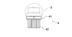
この電動歯ブラシ1は、把持部2の一端から首部3が延び、その先端部にブラシ部4が装着されている。把持部2は、乾電池式、充電池式等の電源部21、これに接続された電気モータ22、電気モータ22の出力軸の一方向への回転を軸31の往復直線運動に変換する伝動部23、及びこれらを収容するハウジング20を備えている。ハウジング20には、電気モータの作動のオンオフを行なうためのスイッチ24が設けられている。首部3は、ハウジング20の一端に着脱自在に結合された筒部30内に軸31を収容している。ブラシ部4は、筒部30の先端部に着脱自在に軸支された植毛台41、該植毛台上の植毛部42、及び筒部30内において軸31と植毛台41の偏心位置に結合されて軸31の往復直線運動を植毛台の往復回動に変換するリンク部43を備えている。これらの構造は、従来の電動歯ブラシと同様であり、また、上記以外の回動型電動歯ブラシの構造を採用することもできる。
【0030】
図3,4,5,6、7,8,9,10は、首部3にブラシ部4を結合した状態を示す正面図、背面図、右側面図、左側面図、平面図、底面図、A−A断面図、B−B断面図である。
【0031】
次に、本発明に係る電動歯ブラシに使用するブラシ部について、毛束の望ましい配置について説明する。図11〜図14は、ブラシ部を植毛側から見た正面図である。これらの電動歯ブラシ用ヘッド(ブラシ部)は、合成繊維を植え込んでなる毛束を備え、電動歯ブラシの動力部であるグリップ部先端に着脱自在に取り付けて使用される。
(第1実施形態)
図11は、ブラシ部の第1の実施形態を示している。このブラシ部4aは、植毛台41上に次のように配置された毛束42を備えている。
第1外周毛束a:植毛面の外周縁に近い第1の円周A上に配置された毛束
第2外周毛束b:第1の円周Aの内側で該円周と同心状をなす第2の円周B上において周方向に見て第1外周毛束aの間に配置された毛束
内部毛束c:第2外周毛束bより内側に配置された毛束
そして、この実施形態においては、第1の円周Aと前記第2の円周Bとの径方向間隔sは、第1外周毛束a及び第2外周毛束bの各半径の和より小さくされている。
【0032】
このように、本実施形態に係る電動歯ブラシにおいては、特に重要な植毛面の外周側にある同心円状の毛束a,bの並びの径方向間隔が各毛束の半径の和より小さい配置とされているので、植毛台が往復回動をすることにより同心円状の毛束の刷掃範囲が径方向に重なる。この重なり部分においては、刷掃範囲間の隙間がなくなるので、植毛面の外周側での磨き残しが防止される。
【0033】
また、植毛位置が規則的に決められているので、製造時の数値制御による位置決めや加工を高い精度で得やすい。また、毛束が整然と並ぶことになるので、美観にも優れ、消費者への訴求度が高い。
【0034】
さらに、第1の円周A上で周方向に隣り合う前記第1外周毛束aの中心角、及び第2の円周B上で周方向に隣り合う前記第2外周毛束bの中心角は、植毛台41の往復回動角以下とするのが望ましい。この実施形態では、60度である。また、毛束の配置により前記中心角は、10度〜90度程度とすることができる。これにより、第1外周毛束及び第2外部毛束による刷掃範囲を、径方向にも周方向にも隙間のない状態又はこれに近い状態で得ることができる。
【0035】
図15は、このブラシ部を用いた電動歯ブラシを、位置を固定して使用した場合に生じる磨き残し部を示している。図に示された中心部の黒い円、その外側の2つの円に磨き残し部が生じているのみであり、従来のものに比し、明らかに磨き残し部が減少している。
(第2実施形態)
図12は、ブラシ部の第2の実施形態を示している。このブラシ部4bは、植毛台41上に次のように配置された毛束42を備えている。
第一外部毛束d:植毛面の外周の近くであって正三角形Cの頂点に相当する位置に配置された毛束
第2外部毛束e:正三角形Cの各辺より植毛面の径方向外方に配置された毛束
第3外部毛束f:正三角形Cの辺に相当する位置に配置された毛束
内部毛束g:第3外部毛束より内側に配置された毛束
そして、正三角形Cの中心と各頂点とを結ぶ直線Dと、相並ぶこれらの直線Dのなす角の2等分線Eとにより形成される扇形領域の各々に、第1外部毛束d、第2外部毛束e、第3外部毛束f及び内部毛束gが存在する。
【0036】
さらに、各扇形領域において、植毛面径方向に見て隣り合う毛束同志を比較したとき、各毛束の半径の和より小さい径方向間隔で各毛束が配置されている。例えば、図12において、正三角形Cの中心と各頂点とを結ぶ直線D1と2等分線Eとにより形成される扇形領域にある毛束について説明すると、以下のものが、ここでいう植毛面径方向に見て隣り合う毛束である。
・第2外部毛束e1と第1外部毛束d1
・第2外部毛束e1と第3外部毛束f2
・第3外部毛束f2と第3外部毛束f1
・第3外部毛束f1と内部毛束g1
これらの毛束が、各毛束の半径の和より小さい径方向間隔(径方向に投射した場合の間隔)で配置されている。
【0037】
この例では、第2外部毛束eは、正三角形の各辺に平行に2個配置されている。このように、毛束を配置することにより、辺に平行な比較的大きな空所に密に毛束が形成されるので、磨き残し部分の発生をより確実に防止できる。
【0038】
また、植毛台41の往復回動角は、正三角形の中心を通って毛束の周縁に引かれた接線であって正三角形の隣り合う頂点に位置する毛束の相向き合う側の接線がなす角の1/2以上であるのが望ましい。また、設定を簡単にするため、正三角形の中心と隣り合う頂点とを結ぶ2直線がなす角の1/2以上、すなわち、60度以上とすることができる。これにより、第1外周毛束、第2外部毛束及び第3外部毛束による刷掃範囲の連続性を高め、磨き残しを減少させることができる。
【0039】
この実施形態では、三角形を基準として毛束を配置したが、他の正多角形を基準とすることもできる。
(第3実施形態)
図13は、ブラシ部の第3の実施形態を示している。このブラシ部4cは、正方形を基準とし、植毛台41上に次のように配置された毛束42を備えている。
第一外部毛束h:植毛面の外周の近くであって正方形Fの頂点に相当する位置に配置された毛束
第2外部毛束i:正方形Fの各辺より植毛面の径方向外方に配置された毛束
第3外部毛束j:正方形Fの辺に相当する位置に配置された毛束
内部毛束k:第3外部毛束より内側に配置された毛束
そして、正方形Fの中心と各頂点とを結ぶ直線Gと、相並ぶこれらの直線Gのなす角の2等分線Hとにより形成される扇形領域の各々に、第1外部毛束h、第2外部毛束i、第3外部毛束j及び内部毛束kが存在する。
【0040】
さらに、各扇形領域において、植毛面径方向に見て隣り合う毛束同志を比較したとき、各毛束の半径の和より小さい径方向間隔で各毛束が配置されている。例えば、図13において、正方形Fの中心と各頂点とを結ぶ直線G1と2等分線Hとにより形成される扇形領域にある毛束について説明すると、以下のものが、ここでいう植毛面径方向に見て隣り合う毛束である。
・第2外部毛束i1と第1外部毛束h1
・第2外部毛束h1と第3外部毛束j1
・第3外部毛束j1と内部毛束k1
これら第1外部毛束h1、第2外部毛束i1、第3外部毛束j1の毛束が、各毛束の半径の和より小さい径方向間隔で配置されている。
【0041】
この例においても、第2外部毛束iは、正方形の各辺に平行に2個配置されている。この配置することにより、辺に平行な比較的大きな空所に密に毛束が形成さ、磨き残し部分の発生をより確実に防止できる。
【0042】
また、この例においても、植毛台41の往復回動角は、正方形の中心を通って毛束の周縁に引かれた接線であって正方形の隣り合う頂点に位置する毛束の相向き合う側の接線がなす角の1/2以上であるのが望ましい。また、設定を簡単にするため、正方形の中心と隣り合う頂点とを結ぶ2直線がなす角の1/2以上、すなわち、45度以上とすることができる。これにより、第1外周毛束及び第2外部毛束による刷掃範囲は、径方向にも周方向にも連続性が高まり、磨き残しを減少することができる。
【0043】
図12及び図13に示す実施形態においては、第1外部毛束、第2外部毛束及び第3外部毛束が上記の配置とされているので、特に重要な植毛面の外周側にある毛束間の磨き残しが確実に防止される。また、毛束が正多角形を基準とした規則的な配置となるので、数値制御を伴った製造工程を経る場合に高い精度を容易に得ることができる上、毛束が整然と並び美観にも優れ、消費者への訴求度が高い。
【0044】
図16及び図17は、図12及び図13に示したブラシ部を用いた電動歯ブラシを、位置を固定して使用した場合に生じる磨き残し部を示している。図16に示された中心部の黒い円及び外周よりの3つの円弧、図17に示された中心部の黒い円及びその外側の円に磨き残し部が生じているのみであり、従来のものに比し、明らかに磨き残し部が減少している。
(第4実施形態)
図14は、ブラシ部の第4の実施形態を示している。このブラシ部4bは、植毛台41上に次のように配置された毛束42を備えている。
第1外部毛束m:植毛面の外周縁の近くに配置され該外周縁に沿って直線で結んだときに正六角形Iをなす毛束
第2外部毛束n:正六角形Iの辺に相当する位置に配置された毛束
第3外部毛束p:正六角形Iの内側において該正六角形に沿うように並べて配置された毛束
内部毛束q:第3外部毛束pより内側に配置された毛束
そして、正六角形の中心と各頂点とを結ぶ直線により形成される扇形領域の各々に、少なくとも第1外部毛束m、第2外部毛束及び第3外部毛束が存在する。
【0045】
さらに、各扇形領域において、植毛面径方向に見て隣り合う毛束同志を比較したとき、各毛束の半径の和より小さい径方向間隔で各毛束が配置されている。例えば、図14において、正六角形Iの中心と頂点とを結ぶ直線J1とJ2とにより形成される扇形領域にある毛束について説明すると、以下のものが、ここでいう植毛面径方向に見て隣り合う毛束である。
・第1外部毛束m1、m2と第2外部毛束n1
・第2外部毛束n1と第3外部毛束p1、p2
この扇形領域では、内部毛束が存在しない。しかし、これに隣り合う扇形領域には、内部毛束q1があり、植毛面径方向に見てこれと隣り合う毛束は、第2外部毛束p2、p3である。歯頸や歯の隅部まで刷掃効果を十分に行き渡らせるためには、内部毛束より外部毛束の方が重要性が高い。したがって、この例のように、隣り合う一つおきの扇形領域に内部毛束を設けるというようにすることも可能であり、必ずしも各扇形領域に内部毛束が存在する必要はない。また、本実施形態において配置の基準とする正多角形は、六角形のように角数が多い凸多角形が特に適しているので、扇形の中心角が比較的小さくなる。この点でも全ての扇形領域に内部毛束が存在する必要はない。
【0046】
上記の隣り合う毛束が、各毛束の半径の和より小さい径方向間隔で配置される。
【0047】
この例においては、植毛台41の往復回動角は、正六角形の中心を通って毛束の周縁に引かれた接線であって前記六多角形の隣り合う頂点に位置する毛束の相向き合う側の接線がなす角度以上であるのが望ましい。この設定を簡単にするために、植毛台41の往復回動角は、正六角形の中心と隣り合う頂点とを結ぶ2直線がなす角以上、すなわち、60度以上とすることができる。これにより、第1外周毛束、第2外部毛束及び第3外部毛束による刷掃範囲は、径方向にも周方向にも連続性が高まり、磨き残しを減少させることができる。
【0048】
この実施形態においては、第1外部毛束、第2外部毛束及び第3外部毛束が上記の配置とされているので、特に重要な植毛面の外周側にある毛束間の磨き残しが確実に防止される。また、毛束が正六角形を基準とした規則的な配置となるので、数値制御を伴った製造工程を経る場合に高い精度を容易に得ることができる上、毛束が整然と並び美観にも優れ、消費者への訴求度が高い。
【0049】
この実施形態では、正六角形を毛束配置の基準としているが、他の多角形を基準とすることもでき、特に正多角形を基準とするのが有利である。
【0050】
このブラシ部を用いた電動歯ブラシを、位置を固定して使用した場合に生じる磨き残し部は、前述の図15に示した状態と同じである。これは、図11の実施形態と図14の実施形態が、同じ毛束配置を備えているからである。第1実施形態ではこれを円を基準として捉え、第4実施形態ではこれを正六角形を基準として捉えている。
(第5実施形態)
次に、ブラシ部の第5実施形態について説明する。この実施形態において、電動歯ブラシのブラシ部は、植毛面の外周縁に近い円周上に配置された複数の最外周毛束と、該最外周毛束より植毛台の径方向内側に配置された内側毛束とを備えている。
【0051】
この配置は、様々な形態をとり得る。例えば、図11に示したブラシ部では、円周A上に配置された毛束aが、ここでいう最外周毛束であり、それより内側の毛束b、cが内側毛束である。また、図12に示したブラシ部では、正三角形Cの頂点を通る円周上に配置された毛束dが最外周毛束であり、その内側の毛束e,f,gが内側毛束である。図13のブラシ部では、正方形Fの外側に配置された毛束iが最外周毛束、その内側の毛束h、j、kが内側毛束である。さらに、図14のブラシ部では、正六角形Iの頂点を通る円周上の毛束mが最外周毛束、その内側の毛束n,p,qが内側毛束である。
【0052】
いずれの例おいても、これらの毛束が植毛面の径方向及び周方向になす離間距離は、植毛台41の往復回動に従ってこれらの毛束が刷掃する面積が、前記円周で囲まれる領域の面積の85%以上であるように決められる。この毛束による刷掃面積は、各毛束の面積、毛束の配置密度、植毛台の往復回動角度によって決まるのであり、毛束を構成するフィラメントの太さや硬さ、駆動装置の電池寿命等を考慮してこれらの適正値を選択し、前記面積割合とする。前記面積割合とすることにより、歯に対する毛束の接触面積が確保され、磨き残しを十分に少なくすることができる。
(その他の形態等)
前記各実施形態において、毛束の長さは、必要に応じて種々に設定することができる。図18は、毛束の長さの設定例を概略的に示している。図18中、(a)は毛束43を植毛面全体で同じ高さとしたもの、(b)は最外周の毛束43aを内側43bの毛束より高くしたもの、(c)は最外周の毛束43cからその隣の周の毛束43dに掛けて上昇する傾斜面を形成し、その内側の毛束43eを低くしたもの、(d)は最外周の毛束43fの隣の周の毛束43gを該最外周の毛束及び内側の毛束43hより高くしたものである。
【0053】
前記実施形態では、植毛台及び毛束の正面形状を円形のものを示したが、本発明はこれに限定されるものでなく、多角形、楕円形等、種々の形とすることができる。また、毛束の径、毛束を構成するフィラメントの寸法や材質は、同一とする他、位置によって異なるものとすることもできる。
【0054】
以上は、本発明を電動歯ブラシに適用した場合の実施形態であるが、本発明は同様にして他の電動ブラシ、例えば、床ブラシ、浴槽洗浄用ブラシ、洗車ブラシ、ガラス清掃用ブラシ等にも適用することができる。
【図面の簡単な説明】
【図1】 本発明の一実施形態に係る電動歯ブラシの斜視図である。
【図2】 図1に示す電動歯ブラシの縦断側面図である。
【図3】 図1に示す電動歯ブラシのブラシ部及び首部を示す正面図である。
【図4】 図1に示す電動歯ブラシのブラシ部及び首部を示す背面図である。
【図5】 図1に示す電動歯ブラシのブラシ部及び首部を示す右側面図である。
【図6】 図1に示す電動歯ブラシのブラシ部及び首部を示す左側面図である。
【図7】 図1に示す電動歯ブラシのブラシ部及び首部を示す平面図である。
【図8】 図1に示す電動歯ブラシのブラシ部及び首部を示す底面図である。
【図9】 図1に示す電動歯ブラシのブラシ部及び首部のA−A断面図である。
【図10】 図1に示す電動歯ブラシのブラシ部及び首部のB−B断面図である。
【図11】 本発明に係る電動歯ブラシに適用されるブラシ部の一形態を概略的に示す正面図である。
【図12】 本発明に係る電動歯ブラシに適用されるブラシ部の他の形態を概略的に示す正面図である。
【図13】 本発明に係る電動歯ブラシに適用されるブラシ部のさらに他の形態を概略的に示す正面図である。
【図14】 本発明に係る電動歯ブラシに適用されるブラシ部のさらに他の形態を概略的に示す正面図である。
【図15】 図11及び図14に示すブラシ部を用いた電動歯ブラシを使用した場合の磨き残し状態を示す説明図である。
【図16】 図12に示すブラシ部を用いた電動歯ブラシを使用した場合の磨き残し状態を示す説明図である。
【図17】 図13に示すブラシ部を用いた電動歯ブラシを使用した場合の磨き残し状態を示す説明図である。
【図18】 本発明に係る電動歯ブラシに適用されるブラシ部の毛束の種々の形態を概略的に示す側面図である。
【図19】 従来の電動歯ブラシにおけるブラシ部の例の正面図及びその磨き残し部の説明図である。
【符号の説明】
1 電動歯ブラシ
2 把持部
3 首部
4,4a,4b,4c,4d ブラシ部
41 植毛台
42 植毛部
a,b,c,d,e,f,g,h,i,j,k,m,n,p,q 毛束
43a,43b,43c,43d,43e,43f,43g,43h 毛束[0001]
BACKGROUND OF THE INVENTION
The present invention relates to an electric brush, and more particularly to an electric brush in which a flocking table reciprocally rotates around the center of the flocked surface along the flocked surface. There are various types of electric brushes such as toothbrushes, floor brushes, bathtub cleaning brushes, car wash brushes, and glass cleaning brushes.
[0002]
[Prior art]
An electric brush, for example, an electric toothbrush, has a type in which a flocking table is reciprocally rotated about the center of the flocked surface along the flocked surface by an electric motor. By applying to the interdental part, the occlusal surface, etc., these parts are cleaned.
[0003]
The flocked portion is formed by arranging a large number of hair bundles at intervals. The reciprocating rotation of the flocking table is usually performed at a rotation angle of about several tens of degrees around the center of the flocking surface. And the several hair | bristle bundle is arrange | positioned in the range of the circumferential direction corresponding to this rotation angle, and a tooth | gear is cleaned by this.
[0004]
[Problems to be solved by the invention]
However, when a conventional electric toothbrush is used, a part of the tooth surface is not sufficiently cleaned, so that a so-called unpolished portion tends to occur.
[0005]
FIG. 19 is a view as seen from the flocked side of the brush portion of the electric toothbrush, and shows a flocking table u and a hair bundle w flocked thereto. For example, when the hair bundle w is arranged concentrically as shown in (a1) in the figure, when the flocking table is reciprocally rotated, as shown in the black area in (a2) in the figure, the hair bundle There will be concentric gaps in the area where the sweeps. As shown in the drawing (b1), even when the hair bundles w are distributed almost uniformly on the flocking table u, as shown in the black area in the drawing (b2), a narrow region where the hair bundles sweep There is a gap.
[0006]
In particular, when brushing the tooth neck portion where plaque is likely to accumulate, the position of the electric toothbrush is temporarily fixed and tooth brushing is performed.
[0007]
Such problems also occur in other electric brushes as well, and if there are many unpolished areas where polishing, cleaning, etc. are not performed in the region within the flocked surface, the cleaning is not sufficiently performed. This causes a problem.
[0008]
The present invention solves such a problem of the conventional electric brush and hardly causes unfinished polishing. In particular, even when the position of the electric brush is temporarily fixed and cleaned, the occurrence of unpolished is prevented. An object of the present invention is to provide an electric brush that can perform the above operation more reliably.
[0009]
[Means for Solving the Problems]
In order to achieve the above object, the present invention provides an electric brush in which a flocking table reciprocates around the center of the flocked surface along the flocked surface, and is arranged on a first circumference close to the outer peripheral edge of the flocked surface. The plurality of first outer peripheral hair bundles arranged between the first outer peripheral hair bundles when viewed in the circumferential direction on the second circumference that is concentric with the circumference inside the first circumference. A second outer peripheral hair bundle, and an inner hair bundle disposed inside the second outer peripheral hair bundle, wherein a radial interval between the first circumference and the second circumference is the first outer circumference An electric brush characterized by being smaller than the sum of the radii of the hair bundle and the second outer circumferential hair bundle. (First invention)
In order to achieve the above object, the present invention also provides an electric brush in which a flocking table reciprocally rotates around the center of the flocked surface along the flocked surface, and has a regular polygonal shape near the outer peripheral edge of the flocked surface. Corresponding to the first external hair bundle arranged at a position corresponding to the apex, the second external hair bundle arranged radially outward of the flocked surface from each side of the regular polygon, and the side of the regular polygon A third outer hair bundle arranged at a position where the inner hair bundle is arranged, and an inner hair bundle arranged inside the third outer hair bundle, and connects the center of the regular polygon and each vertex on the flocked surface. At least the first outer hair bundle, the second outer hair bundle, and the third outer hair bundle are present in each of the fan-shaped regions formed by the straight lines and the bisectors of the angles formed by these straight lines, In each fan-shaped region, among the first outer hair bundle, the second outer hair bundle, and the third outer hair bundle, the diameter direction of the flocked surface When comparing the tufts comrades adjacent look, there is provided an electric brush, characterized in that each bristle bundle with a small radial distance than the radius of the sum of the capillary bundles are positioned. (Second invention)
In order to achieve the above object, the present invention further provides an electric brush in which a flocking table reciprocally rotates around the center of the flocked surface along the flocked surface and is arranged near the outer peripheral edge of the flocked surface. A first outer hair bundle that forms a convex polygon when tied along a straight line, a second outer hair bundle disposed at a position corresponding to a side of the convex polygon, and the convex inside the convex polygon A third outer hair bundle arranged side by side along the polygon, and an inner hair bundle arranged inside the third outer hair bundle, and a straight line connecting the center of the convex polygon and each vertex At least the first external hair bundle, the second external hair bundle, and the third external hair bundle are present in each of the fan-shaped regions, and in each sector-shaped region, the first external hair bundle, the second external hair bundle, and Of the third external hair bundles, when comparing adjacent hair bundles as seen in the radial direction of the flocked surface, each hair bundle It is intended to provide an electric brush, wherein each hair bundle at a small radial spacing than the sum of the radius is located. (Third invention)
In order to achieve the above object, the present invention further provides an electric brush in which a flocking table reciprocally rotates around the center of the flocked surface along the flocked surface, and is arranged on a circumference close to the outer peripheral edge of the flocked surface. A plurality of outermost hair bundles, and inner hair bundles arranged on the radially inner side of the flocking table from the outermost hair bundle, and the separation distance between these hair bundles in the radial direction and circumferential direction of the flocked surface is Provided is an electric brush characterized in that the area to which these hair bundles are brushed is determined to be 85% or more of the area surrounded by the circumference in accordance with the reciprocating rotation of the flocking table. It is. (Fourth invention)
In the present invention, when the hair bundle is present at a certain position, unless otherwise specified, it refers to the case where the hair bundle is exactly located, and the case where the brushing action is substantially obtained at that position. For example, a hair bundle being arranged at a certain point such as a vertex of a polygon means an arrangement in which the point exists in a range within 2/3 of the distance from the center of the hair bundle to the outer periphery. . In addition, a hair bundle is arranged on a certain line such as a circumference or a polygonal side means that the line is within a range of 2/3 of the distance from the center of the hair bundle to the outer circumference. An arrangement that exists. Further, that a hair bundle is present in a certain region such as a fan shape means that ¼ or more of the area of the hair bundle is present in that region.
[0010]
【The invention's effect】
According to the present invention, an electric brush having the following effects can be provided. In order to obtain a good brushing effect without leaving any unpolished surface in an electric brush in which the flocking table reciprocates around the center of the flocked surface along the flocked surface, the flocked portion should be in contact with the surface to be cleaned as much as possible. is required. In particular, when the flocked part is applied to the surface to be cleaned and held at the same position, and the contact state with the surface to be cleaned is observed as the flocking table is reciprocated, the hair bundle and the cleaned object in the region of the flocked part It is important that the contact with the surface is as close as possible. In the case of an electric toothbrush, in particular, in order to improve the cleanability of the tooth neck where plaque is likely to accumulate, it is important to prevent occurrence of unpolished on the outer peripheral side of the flocked surface.
[0011]
In this invention, in 1st invention, the 1st outer periphery hair | bristle bundle on the 1st circumference close to the outer periphery of the said flocked surface, and the 2nd circumference which makes concentric form inside the said 1st circumference A second outer circumferential hair bundle disposed between the first outer circumferential hair bundles when viewed in the circumferential direction above, and an inner hair bundle disposed inside the second outer circumferential hair bundle, the first circumference; The radial distance from the second circumference is smaller than the sum of the radii of the first outer bristle bundle and the second outer bristle bundle.
[0012]
In this way, since the radial interval of the arrangement of concentric hair bundles on the outer peripheral side of the particularly important flocked surface is arranged smaller than the sum of the radii of the respective hair bundles, the flocking table reciprocally rotates. As a result, the brushing range of the concentric bristles overlaps in the radial direction. In this overlapping portion, there is no gap between the brushing ranges. Therefore, unpolished left on the outer peripheral side of the flocked surface is prevented.
[0013]
In addition, in the formation of the hair transplant part of the electric brush, there is positioning and fixing of the hair bundle (depending on the manufacturing method, formation of the flock hole and fixing with a flat wire, heat welding of the hair bundle base end, integral molding by in-mold, etc. ) Etc., it is common to go through a manufacturing process with numerical control. According to the first aspect of the present invention, the regular arrangement of the hair bundles is adopted with reference to the concentric circles, which is advantageous in accurately specifying the position and processing based on the numerical control. Moreover, since the hair bundles are arranged in an orderly manner, it is excellent in aesthetics and has a high appeal to consumers.
[0014]
Further, a tangent line drawn to a peripheral edge of the hair bundle through the center of the first circumference, and an angle formed by the tangent lines on the opposite sides of adjacent hair bundles on the first circumference, and the first The angle formed by the tangents drawn to the periphery of the hair bundle through the center of the circumference of 2 and the tangents on the opposite sides of the neighboring hair bundles on the second circumference is the reciprocation of the flocking table. It is desirable that it is less than the rotation angle. In order to simplify this setting, the central angle of the first outer circumferential hair bundle adjacent in the circumferential direction on the first circumference and the second outer circumferential hair bundle adjacent in the circumferential direction on the second circumference. The center angle can be made equal to or less than the reciprocating rotation angle of the flocking table. Accordingly, the continuity of the brushing range by the first outer bristle bundle and the second outer bristle bundle is increased in both the radial direction and the circumferential direction, and the unpolished portion can be reduced.
[0015]
In the present invention, in the second invention, the first external hair bundle arranged near the outer peripheral edge of the flocked surface and corresponding to the vertex of the regular polygon, and flocked from each side of the regular polygon A second outer hair bundle arranged radially outward of the surface, a third outer hair bundle arranged at a position corresponding to the side of the regular polygon, and an inner side of the third outer hair bundle. It has an internal hair bundle.
[0016]
In the state in which the third outer hair bundle is arranged at a position corresponding to the side of the regular polygon, in addition to the case where the center of the third outer hair bundle is on the side of the regular polygon, the regular polygon This includes the case where at least a part of one third outer hair bundle is located in the width region when the first outer hair bundles located at adjacent vertices are connected by a width passing through each outer peripheral edge.
[0017]
In the second invention, since the hair bundles are regularly arranged based on the regular polygon as described above, it is advantageous to accurately specify and process the position based on numerical control in the manufacturing process. . In addition, an excellent aesthetic appearance and a high degree of appeal to consumers can be obtained from the orderly arrangement of hair bundles.
[0018]
Furthermore, in the second invention, at least each of the fan-shaped regions formed by a straight line connecting the center of the regular polygon and each vertex and a bisector of an angle formed by these straight lines. 1 external hair bundle, 2nd external hair bundle, and 3rd external hair bundle exist, and each fan-shaped area WHEREIN: Of the said 1st external hair bundle, the 2nd external hair bundle, and the 3rd external hair bundle, the flocked surface radial direction When the adjacent hair bundles are compared with each other, the hair bundles are arranged at a radial interval smaller than the sum of the radii of the respective hair bundles. Since the first outer hair bundle, the second outer hair bundle, and the third outer hair bundle on the outer peripheral side of the particularly important flocked surface are arranged in this manner, a fan-shaped table is formed by reciprocating rotation of the flocked table. The range of brush bristles in the region overlaps in the radial direction. In this overlapped portion, there is no gap between the brushing ranges, so that unpolished portions on the outer peripheral side of the flocked surface are prevented.
[0019]
It is desirable that a plurality of the second external hair bundles are arranged in a direction along each side of the regular polygon. Thereby, since the hair bundle is densely formed in a relatively large space parallel to the side of the regular polygon, it is possible to further reduce the unpolished portion.
[0020]
The reciprocating rotation angle of the flocking table is a tangent drawn to the periphery of the hair bundle through the center of the regular polygon, and the opposite sides of the hair bundle located at adjacent vertices of the regular polygon Is ½ or more of the angle formed by the tangent line. In order to simplify this setting, the reciprocating rotation angle of the flocking table is 1 / of the angle formed by the tangent line passing through the peripheral edge of the hair bundle located at each adjacent vertex and the center of the regular polygon. It can be 2 or more. Accordingly, the continuity in the circumferential direction is increased in the brushing range of the first outer hair bundle, the second outer hair bundle, and the third outer hair bundle in the adjacent fan-shaped regions, and the brushing range by these outer hair bundles. Can be made into a state with little unpolished.
[0021]
In the present invention, in the third invention, a first outer hair bundle that is arranged near the outer peripheral edge of the flocked surface and forms a convex polygon when tied in a straight line along the outer peripheral edge, and the convex polygon A second outer hair bundle arranged at a position corresponding to the side, a third outer hair bundle arranged side by side along the convex polygon inside the convex polygon, and an inner side from the third outer hair bundle And an inner hair bundle arranged in the.
[0022]
In the state where the second outer hair bundle is arranged at a position corresponding to the side of the convex polygon, in addition to the case where the center of the second outer hair bundle is on the side of the convex polygon, This includes the case where the second external hair bundle is located in the width region when the first external hair bundles located at adjacent vertices are connected by a width passing through each outer peripheral edge.
[0023]
In the third invention, since the hair bundles are regularly arranged on the basis of the convex polygon as described above, it is easy to accurately specify and process the position based on numerical control in the manufacturing process. In addition, an excellent aesthetic appearance and a high degree of appeal to consumers can be obtained from the orderly arrangement of hair bundles.
[0024]
Furthermore, in the third invention, at least the first outer hair bundle, the second outer hair bundle, and the third outer hair bundle are formed in each of the sector regions formed by straight lines connecting the centers of the convex polygons and the vertices. When each of the fan-shaped regions is compared with each other in the first outer hair bundle, the second outer hair bundle, and the third outer hair bundle, the hair bundles adjacent to each other when viewed in the radial direction of the flocked surface. The hair bundles are arranged at a radial interval smaller than the sum of the radii. Since the first outer hair bundle, the second outer hair bundle, and the third outer hair bundle on the outer peripheral side of the particularly important flocked surface are arranged in this manner, a fan-shaped table is formed by reciprocating rotation of the flocked table. The range of brush bristles in the region overlaps in the radial direction. In this overlapped portion, there is no gap between the brushing ranges, so that unpolished portions on the outer peripheral side of the flocked surface are prevented.
[0025]
In addition, the reciprocating rotation angle of the flocking table is a tangent drawn to the periphery of the hair bundle through the center of the regular polygon, and the reciprocating rotation angle of the flocking table is adjacent to the regular polygon. The angle is preferably equal to or greater than the angle formed by the tangents on the opposite sides of the hair bundle located at the apex. In order to simplify this setting, the reciprocating rotation angle of the flocking table is greater than or equal to the angle formed by the tangent line passing through the peripheral edge of the opposite side of the hair bundle located at each adjacent vertex and the center of the convex polygon. It is desirable. Accordingly, the brushing ranges of the first outer hair bundle, the second outer hair bundle, and the third outer hair bundle in the adjacent fan-shaped regions increase the continuity in the circumferential direction, and the cleaning range by these outer hair bundles is increased. It can be in a state where there is little unpolished. The convex polygon is preferably a regular polygon.
[0026]
In the present invention, in the fourth invention, a plurality of outermost peripheral hair bundles arranged on the circumference close to the outer peripheral edge of the flocked surface, and an inner side arranged radially inward of the flocking table from the outermost peripheral hair bundle The separation distance between the hair bundles in the radial direction and the circumferential direction of the flocked surface is a region surrounded by the circumference of the area where these hair bundles are wiped according to the reciprocating rotation of the flocking table. It is determined to be 85% or more of the area.
[0027]
In the fourth invention, in this way, by setting the area ratio, the brushing area of the outermost hair bundle and the inner hair bundle according to the reciprocating rotation of the flocking table is the area of the region surrounded by the circumference. On the other hand, since the ratio is determined to be the above-mentioned ratio, the contact area of the hair bundle with the teeth is ensured, and the unpolished portion can be sufficiently reduced.
[0028]
DETAILED DESCRIPTION OF THE INVENTION
Hereinafter, an embodiment when the present invention is applied to an electric toothbrush will be described with reference to the accompanying drawings. FIG. 1 is a perspective view showing the entire electric toothbrush, and FIG. 2 is a longitudinal sectional view thereof.
[0029]
The
[0030]
3, 4, 5, 6, 7, 8, 9, and 10 are a front view, a rear view, a right side view, a left side view, a plan view, a bottom view, and a state in which the
[0031]
Next, the desirable arrangement of the hair bundle will be described for the brush portion used in the electric toothbrush according to the present invention. FIGS. 11-14 is the front view which looked at the brush part from the flocking side. These electric toothbrush heads (brush portions) are provided with bristles in which synthetic fibers are implanted, and are detachably attached to the tip of a grip portion which is a power portion of the electric toothbrush.
(First embodiment)
FIG. 11 shows a first embodiment of the brush portion. This
1st outer periphery hair | bristle bundle a: The hair | bristle bundle arrange | positioned on the 1st circumference A near the outer periphery of the flocked surface
2nd outer periphery hair | bristle bundle b: The hair arrange | positioned between the 1st outer periphery hair | bristle bundle a seeing in the circumferential direction on the 2nd circumference B concentric with this circumference inside the 1st circumference A bundle
Inner hair bundle c: hair bundle arranged inside the second outer circumferential hair bundle b
In this embodiment, the radial interval s between the first circumference A and the second circumference B is smaller than the sum of the radii of the first outer hair bundle a and the second outer hair bundle b. Has been.
[0032]
As described above, in the electric toothbrush according to the present embodiment, the arrangement in which the radial interval between the concentric bristles a and b on the outer peripheral side of the particularly important flocked surface is smaller than the sum of the radii of the bristles. As a result, the brushing table reciprocally rotates, so that the concentric bristles of the bristles overlap in the radial direction. In this overlapped portion, there is no gap between the brushing ranges, so that unpolished on the outer peripheral side of the flocked surface is prevented.
[0033]
Moreover, since the flocking position is regularly determined, it is easy to obtain positioning and processing by numerical control at the time of manufacture with high accuracy. Moreover, since the hair bundles are arranged in an orderly manner, it is excellent in aesthetics and has a high appeal to consumers.
[0034]
Further, the central angle of the first outer peripheral hair bundle a adjacent in the circumferential direction on the first circumference A and the central angle of the second outer peripheral hair bundle b adjacent in the circumferential direction on the second circumference B. Is preferably equal to or smaller than the reciprocating rotation angle of the flocking table 41. In this embodiment, it is 60 degrees. The central angle can be set to about 10 to 90 degrees depending on the arrangement of the hair bundles. Thereby, the brushing range by the 1st outer periphery hair | bristle bundle and the 2nd outer hair | bristle bundle can be obtained in the state which has no clearance gap in the radial direction and the circumferential direction, or a state close | similar to this.
[0035]
FIG. 15 shows an unpolished portion that occurs when the electric toothbrush using this brush portion is used with its position fixed. Only the black circle at the center shown in the figure and the two circles outside the circle are left unpolished, and the unpolished portion is clearly reduced as compared with the conventional one.
(Second Embodiment)
FIG. 12 shows a second embodiment of the brush portion. This
First external hair bundle d: hair bundle arranged near the outer periphery of the flocked surface and corresponding to the apex of the regular triangle C
2nd external hair | bristle bundle e: The hair | bristle bundle arrange | positioned from each side of the equilateral triangle C to the radial direction outer side of the flocked surface
3rd external hair | bristle bundle f: The hair | bristle bundle arrange | positioned in the position corresponded to the edge | side of the equilateral triangle C
Inner hair bundle g: Hair bundle arranged inside the third outer hair bundle
Then, in each of the sector regions formed by the straight line D connecting the center of the regular triangle C and each vertex and the bisector E of the angle formed by these straight lines D, the first outer hair bundle d, There are a second outer hair bundle e, a third outer hair bundle f, and an inner hair bundle g.
[0036]
Furthermore, in each fan-shaped region, when the adjacent hair bundles as viewed in the radial direction of the flocked surface are compared, the hair bundles are arranged at a radial interval smaller than the sum of the radii of the respective hair bundles. For example, in FIG. 12, a hair bundle in a fan-shaped region formed by a straight line D1 connecting the center of each equilateral triangle C and each vertex and a bisector E will be described. It is a hair bundle adjacent when seen in the radial direction.
The second outer hair bundle e1 and the first outer hair bundle d1
The second outer hair bundle e1 and the third outer hair bundle f2
Third outer hair bundle f2 and third outer hair bundle f1
Third hair bundle f1 and inner hair bundle g1
These hair bundles are arranged at a radial interval smaller than the sum of the radii of the respective hair bundles (interval when projected in the radial direction).
[0037]
In this example, two second external hair bundles e are arranged in parallel to each side of the equilateral triangle. By arranging the hair bundles in this way, the hair bundles are densely formed in a relatively large space parallel to the side, so that it is possible to more reliably prevent the occurrence of unpolished portions.
[0038]
Further, the reciprocating rotation angle of the flocking table 41 is a tangent drawn to the periphery of the hair bundle through the center of the equilateral triangle and a tangent on the opposite side of the hair bundle located at the adjacent vertex of the equilateral triangle. It is desirable to be at least 1/2 of the corner. Further, in order to simplify the setting, it can be set to 1/2 or more of the angle formed by two straight lines connecting the center of the regular triangle and the adjacent vertex, that is, 60 degrees or more. Thereby, the continuity of the brushing range by the 1st outer periphery hair | bristle bundle, the 2nd outer hair | bristle bundle, and the 3rd outer hair | bristle bundle can be improved, and unpolished can be decreased.
[0039]
In this embodiment, the hair bundle is arranged with reference to a triangle, but other regular polygons may be used as a reference.
(Third embodiment)
FIG. 13 shows a third embodiment of the brush portion. This
First external hair bundle h: hair bundle arranged near the outer periphery of the flocked surface and corresponding to the apex of the square F
2nd external hair | bristle bundle i: The hair | bristle bundle arrange | positioned from the each side of the square F to the radial direction outer side of the flocked surface
3rd external hair | bristle bundle j: The hair | bristle bundle arrange | positioned in the position corresponded to the edge of the square F
Inner hair bundle k: hair bundle arranged inside the third outer hair bundle
Then, each of the fan-shaped regions formed by the straight line G connecting the center of the square F and each vertex and the bisector H of the angle formed by these straight lines G is arranged in the first external hair bundle h, There are two outer hair bundles i, a third outer hair bundle j, and an inner hair bundle k.
[0040]
Furthermore, in each fan-shaped region, when the adjacent hair bundles as viewed in the radial direction of the flocked surface are compared, the hair bundles are arranged at a radial interval smaller than the sum of the radii of the respective hair bundles. For example, in FIG. 13, the hair bundle in the fan-shaped region formed by the straight line G <b> 1 connecting the center of the square F and each vertex and the bisector H will be described. It is a hair bundle adjacent to each other when viewed in the direction.
The second outer hair bundle i1 and the first outer hair bundle h1
The second outer hair bundle h1 and the third outer hair bundle j1
Third hair bundle j1 and inner hair bundle k1
The hair bundles of the first external hair bundle h1, the second external hair bundle i1, and the third external hair bundle j1 are arranged at radial intervals smaller than the sum of the radii of the respective hair bundles.
[0041]
Also in this example, two second external hair bundles i are arranged in parallel to each side of the square. With this arrangement, hair bundles are densely formed in a relatively large space parallel to the side, and generation of unpolished portions can be prevented more reliably.
[0042]
Also in this example, the reciprocating rotation angle of the flocking table 41 is a tangent drawn to the peripheral edge of the hair bundle through the center of the square and on the opposite side of the hair bundle located at the adjacent vertex of the square. It is desirable that the angle is ½ or more of the angle formed by the tangent line. Further, in order to simplify the setting, the angle can be set to 1/2 or more of the angle formed by the two straight lines connecting the center of the square and the adjacent vertex, that is, 45 degrees or more. Thereby, the brushing range by the 1st outer periphery hair | bristle bundle and the 2nd outer hair | bristle bundle can increase continuity in a radial direction and a circumferential direction, and can reduce unpolished.
[0043]
In the embodiment shown in FIGS. 12 and 13, the first outer hair bundle, the second outer hair bundle, and the third outer hair bundle are arranged as described above. Unpolished unbundling between bundles is surely prevented. In addition, since the hair bundles are regularly arranged based on regular polygons, high accuracy can be easily obtained when a manufacturing process with numerical control is performed, and the hair bundles are arranged in an orderly manner. Excellent and appealing to consumers.
[0044]
FIGS. 16 and 17 show unpolished portions that occur when the electric toothbrush using the brush portion shown in FIGS. 12 and 13 is used in a fixed position. Only the black circle in the center shown in FIG. 16 and three arcs from the outer periphery, the black circle in the center shown in FIG. 17 and the outer circle are left unpolished. Compared with, the unpolished part is clearly reduced.
(Fourth embodiment)
FIG. 14 shows a fourth embodiment of the brush portion. This
First external hair bundle m: a hair bundle that is arranged near the outer peripheral edge of the flocked surface and forms a regular hexagon I when tied in a straight line along the outer peripheral edge
2nd external hair | bristle bundle n: The hair | bristle bundle arrange | positioned in the position corresponded to the edge | side of the regular hexagon I
Third external hair bundle p: hair bundle arranged side by side along the regular hexagon inside the regular hexagon I
Inner hair bundle q: Hair bundle arranged inside the third outer hair bundle p
Then, at least the first outer hair bundle m, the second outer hair bundle, and the third outer hair bundle exist in each of the sector regions formed by straight lines connecting the center of the regular hexagon and each vertex.
[0045]
Furthermore, in each fan-shaped region, when the adjacent hair bundles as viewed in the radial direction of the flocked surface are compared, the hair bundles are arranged at a radial interval smaller than the sum of the radii of the respective hair bundles. For example, in FIG. 14, the hair bundle in the fan-shaped region formed by the straight lines J <b> 1 and J <b> 2 connecting the center and the vertex of the regular hexagon I will be described. Adjacent hair bundles.
First outer hair bundles m1, m2 and second outer hair bundle n1
The second outer hair bundle n1 and the third outer hair bundle p1, p2
In this sector area, there are no internal hair bundles. However, in the fan-shaped region adjacent to this, there is an inner hair bundle q1, and the hair bundle adjacent to this when viewed in the radial direction of the planted surface is the second outer hair bundle p2, p3. In order to sufficiently spread the brushing effect to the tooth neck and the corner of the tooth, the outer hair bundle is more important than the inner hair bundle. Therefore, as in this example, it is possible to provide inner hair bundles in every other sectoral area adjacent to each other, and it is not always necessary to have an inner hair bundle in each sectoral area. In addition, the regular polygon which is the reference for arrangement in the present embodiment is particularly suitable as a convex polygon having a large number of corners such as a hexagon, so that the central angle of the sector is relatively small. In this respect as well, it is not necessary that the inner hair bundle exists in all the fan-shaped regions.
[0046]
The adjacent hair bundles are arranged at radial intervals smaller than the sum of the radii of the respective hair bundles.
[0047]
In this example, the reciprocating rotation angle of the flocking table 41 is a tangent drawn to the periphery of the hair bundle through the center of the regular hexagon, and the hair bundles located at the adjacent apexes of the six polygons face each other. It is desirable that the angle is greater than the angle formed by the tangent on the side. In order to simplify this setting, the reciprocating rotation angle of the flocking table 41 can be set to be equal to or greater than the angle formed by two straight lines connecting the center of the regular hexagon and the adjacent vertex, that is, 60 degrees or greater. Thereby, the continuity increases in the radial direction and the circumferential direction in the cleaning range by the first outer bristle bundle, the second outer bristle bundle, and the third outer bristle bundle, and it is possible to reduce the unpolished portion.
[0048]
In this embodiment, since the 1st external hair bundle, the 2nd external hair bundle, and the 3rd external hair bundle are made into the above-mentioned arrangement, the unpolished portion between the hair bundles on the outer peripheral side of the flocked surface is particularly important. It is surely prevented. In addition, since the hair bundles are regularly arranged based on regular hexagons, high accuracy can be easily obtained through a manufacturing process with numerical control, and the hair bundles are neatly arranged and excellent in aesthetics. , Consumer appeal is high.
[0049]
In this embodiment, the regular hexagon is used as a reference for arranging the hair bundle, but other polygons can be used as a reference, and it is particularly advantageous to use the regular polygon as a reference.
[0050]
The unpolished portion that occurs when the electric toothbrush using this brush portion is used in a fixed position is the same as the state shown in FIG. This is because the embodiment of FIG. 11 and the embodiment of FIG. 14 have the same hair bundle arrangement. In the first embodiment, this is regarded as a reference to a circle, and in the fourth embodiment, this is regarded as a regular hexagon.
(Fifth embodiment)
Next, a fifth embodiment of the brush portion will be described. In this embodiment, the brush part of the electric toothbrush is arranged on the radially inner side of the flocking table with a plurality of outermost peripheral hair bundles arranged on the circumference near the outer peripheral edge of the flocked surface, and the outermost peripheral hair bundle. It has an inner hair bundle.
[0051]
This arrangement can take a variety of forms. For example, in the brush part shown in FIG. 11, the hair bundle a arranged on the circumference A is the outermost hair bundle here, and the hair bundles b and c on the inner side are inner hair bundles. Moreover, in the brush part shown in FIG. 12, the hair | bristle bundle d arrange | positioned on the circumference which passes along the vertex of the equilateral triangle C is an outermost outer periphery hair | bristle bundle, and the inner hair | bristle bundle e, f, and g are inner side hair | bristle bundles. It is. In the brush part of FIG. 13, the hair bundle i arranged on the outer side of the square F is the outermost peripheral hair bundle, and the inner hair bundles h, j, k are inner hair bundles. Further, in the brush portion of FIG. 14, the hair bundle m on the circumference passing through the apex of the regular hexagon I is the outermost hair bundle, and the inner hair bundles n, p, and q are inner hair bundles.
[0052]
In any example, the separation distance between these hair bundles in the radial direction and the circumferential direction of the flocked surface is such that the area where these hair bundles are cleaned according to the reciprocating rotation of the flocking table 41 is surrounded by the circumference. It is determined to be 85% or more of the area of the area to be processed. The brushing area of the hair bundle is determined by the area of each hair bundle, the arrangement density of the hair bundle, and the reciprocating rotation angle of the flocking table, and the thickness and hardness of the filament constituting the hair bundle, and the battery life of the driving device. These appropriate values are selected in consideration of the above, and the area ratio is set. By setting it as the said area ratio, the contact area of the hair | bristle bundle with respect to a tooth | gear is ensured, and unpolished can be fully reduced.
(Other forms)
In each said embodiment, the length of a hair | bristle bundle can be set variously as needed. FIG. 18 schematically shows an example of setting the length of the hair bundle. In FIG. 18, (a) shows the
[0053]
In the said embodiment, although the front shape of the flock base and the hair | bristle bundle was shown circular, this invention is not limited to this, It can be set as various shapes, such as a polygon and an ellipse. In addition, the diameter of the hair bundle and the dimensions and materials of the filaments constituting the hair bundle can be the same or different depending on the position.
[0054]
The above is an embodiment when the present invention is applied to an electric toothbrush, but the present invention is similarly applied to other electric brushes such as a floor brush, a bathtub cleaning brush, a car wash brush, a glass cleaning brush, and the like. Can be applied.
[Brief description of the drawings]
FIG. 1 is a perspective view of an electric toothbrush according to an embodiment of the present invention.
FIG. 2 is a vertical side view of the electric toothbrush shown in FIG.
3 is a front view showing a brush part and a neck part of the electric toothbrush shown in FIG. 1. FIG.
4 is a rear view showing a brush part and a neck part of the electric toothbrush shown in FIG. 1. FIG.
5 is a right side view showing a brush part and a neck part of the electric toothbrush shown in FIG. 1. FIG.
6 is a left side view showing a brush part and a neck part of the electric toothbrush shown in FIG. 1. FIG.
7 is a plan view showing a brush part and a neck part of the electric toothbrush shown in FIG. 1. FIG.
8 is a bottom view showing a brush part and a neck part of the electric toothbrush shown in FIG. 1. FIG.
9 is a cross-sectional view taken along line AA of the brush portion and the neck portion of the electric toothbrush shown in FIG. 1. FIG.
10 is a BB cross-sectional view of the brush portion and the neck portion of the electric toothbrush shown in FIG. 1. FIG.
FIG. 11 is a front view schematically showing one embodiment of a brush portion applied to the electric toothbrush according to the present invention.
FIG. 12 is a front view schematically showing another form of a brush portion applied to the electric toothbrush according to the present invention.
FIG. 13 is a front view schematically showing still another embodiment of the brush portion applied to the electric toothbrush according to the present invention.
FIG. 14 is a front view schematically showing still another embodiment of the brush portion applied to the electric toothbrush according to the present invention.
FIG. 15 is an explanatory diagram showing a state of unpolished when an electric toothbrush using the brush part shown in FIGS. 11 and 14 is used.
16 is an explanatory diagram showing a state of an unpolished state when an electric toothbrush using the brush portion shown in FIG. 12 is used.
FIG. 17 is an explanatory diagram showing a state where an electric toothbrush using the brush portion shown in FIG.
FIG. 18 is a side view schematically showing various forms of a bristle bundle of a brush portion applied to the electric toothbrush according to the present invention.
FIG. 19 is a front view of an example of a brush portion in a conventional electric toothbrush and an explanatory view of a portion left unpolished.
[Explanation of symbols]
1 Electric toothbrush
2 gripping part
3 neck
4, 4a, 4b, 4c, 4d Brush part
41 Flocking table
42 Flocking
a, b, c, d, e, f, g, h, i, j, k, m, n, p, q
43a, 43b, 43c, 43d, 43e, 43f, 43g, 43h
Claims (4)
前記植毛面上に毛束が相互に間隔をおいて配置されており、
前記植毛面の外周縁に近い第1の円周上に配置された複数の第1外周毛束と、
前記第1の円周の内側で該円周と同心状をなす第2の円周上において周方向に見て前記第1外周毛束の間に配置された第2外周毛束と、
該第2外周毛束より内側に配置された内部毛束とを備え、
前記第1の円周と前記第2の円周との径方向間隔が、前記第1外周毛束及び第2外周毛束の各半径の和より小さく、
前記第1の円周の中心を通って毛束の周縁に引かれた接線であって前記第1の円周上の隣り合う毛束の相向き合う側の接線がなす角、及び前記第2の円周の中心を通って毛束の周縁に引かれた接線であって前記第2の円周上の隣り合う毛束の相向き合う側の接線がなす角が、各々前記植毛台の往復回動角以下であり、
これら毛束が植毛面の径方向及び周方向になす離間距離は、前記植毛台の往復回動に従ってこれらの毛束が刷掃する面積が、前記円周で囲まれる領域の面積の85%以上となるように決められていることを特徴とする電動歯ブラシ。In the electric toothbrush of bristles table is reciprocatingly rotated around the center of the plant hair surface along the flocked surface,
The hair bundles are arranged on the flocked surface at intervals,
A plurality of first outer hair bundles arranged on a first circumference close to the outer peripheral edge of the flocked surface;
A second outer bristle bundle disposed between the first outer bristle bundles when viewed in the circumferential direction on a second circumference concentric with the circumference inside the first circumference;
An inner hair bundle disposed inside the second outer circumferential hair bundle,
Radial distance between the first circumferential and the second circumference, rather less than the sum of the radius of the first outer peripheral bristle tufts and a second outer peripheral bristle tufts,
A tangent line that is drawn to the periphery of the hair bundle through the center of the first circumference and formed by a tangent line on the opposite side of adjacent hair bundles on the first circumference, and the second Reciprocal rotation of the flocking table is defined by tangent lines drawn to the periphery of the hair bundle through the center of the circumference and formed by tangents on the opposite sides of adjacent hair bundles on the second circumference. Below the corner,
The separation distance between these hair bundles in the radial direction and the circumferential direction of the flocked surface is such that the area that these hair bundles are wiped in accordance with the reciprocating rotation of the flocking table is 85% or more of the area surrounded by the circumference. electric toothbrush, characterized in that are determined so as to be.
前記植毛面上に毛束が相互に間隔をおいて配置されており、
前記植毛面の外周縁の近くであって該外周縁に沿って直線で結んだときに正多角形の頂点に相当する位置に配置された第1外部毛束と、
前記正多角形の各辺より植毛面の径方向外方に配置された第2外部毛束と、
前記正多角形の辺に相当する位置に配置された第3の外部毛束と、
前記第3外部毛束より内側に配置された内部毛束とを備え、
前記植毛面において、前記正多角形の中心と各頂点とを結ぶ直線と、相並ぶこれらの直線のなす角の2等分線とにより形成される扇形領域の各々に、少なくとも前記第1外部毛束、第2外部毛束及び第3外部毛束が存在し、
各扇形領域において、前記第1外部毛束、第2外部毛束及び第3外部毛束の内、植毛面径方向に見て隣り合う毛束同志を比較したとき、各毛束の半径の和より小さい径方向間隔で各毛束が配置されており、
前記植毛台の往復回動角が、前記正多角形の中心を通って毛束の周縁に引かれた接線であって前記正多角形の隣り合う頂点に位置する毛束の相向き合う側の接線がなす角の1/2以上であり、
これら毛束が植毛面の径方向及び周方向になす離間距離は、前記植毛台の往復回動に従ってこれらの毛束が刷掃する面積が、前記正多角形の頂点を通る円周で囲まれる領域の面積の85%以上となるように決められていることを特徴とする電動歯ブラシ。In the electric toothbrush of bristles table is reciprocatingly rotated around the center of the plant hair surface along the flocked surface,
The hair bundles are arranged on the flocked surface at intervals,
A first outer hair bundle disposed near the outer peripheral edge of the flocked surface and arranged at a position corresponding to the apex of the regular polygon when tied in a straight line along the outer peripheral edge ;
A second outer hair bundle disposed radially outward of the flocked surface from each side of the regular polygon;
A third outer hair bundle arranged at a position corresponding to the side of the regular polygon;
An inner hair bundle disposed inside the third outer hair bundle,
In the flocked surface, at least the first external hair is formed in each of the sector regions formed by the straight line connecting the center of the regular polygon and each vertex and the bisector of the angle formed by these straight lines. A bundle, a second outer hair bundle, and a third outer hair bundle,
In each fan-shaped region, among the first external hair bundle, the second external hair bundle, and the third external hair bundle, when the adjacent hair bundles viewed in the radial direction of the flocked surface are compared, the sum of the radii of the respective hair bundles Each hair bundle is arranged at smaller radial intervals ,
The reciprocating rotation angle of the flock is a tangent drawn to the periphery of the hair bundle through the center of the regular polygon, and the tangent on the opposite side of the hair bundle located at the adjacent vertex of the regular polygon More than half of the angle formed by
The separation distance formed by the hair bundles in the radial direction and the circumferential direction of the flocked surface is surrounded by the circumference passing through the apex of the regular polygon so that the area of the bristles is wiped according to the reciprocating rotation of the flocking table. electric toothbrush, characterized in that are determined such that more than 85% of the area of the region.
前記植毛面上に毛束が相互に間隔をおいて配置されており、
前記植毛面の外周縁の近くであって該外周縁に沿って直線で結んだときに正多角形の頂点に相当する位置に配置された第1外部毛束と、
前記正多角形の辺に相当する位置に配置された第2外部毛束と、
前記正多角形の内側において該正多角形に沿うように並べて配置された第3外部毛束と、
該第3外部毛束より内側に配置された内部毛束とを備え、
前記正多角形の中心と各頂点とを結ぶ直線により形成される扇形領域の各々に、少なくとも前記第1外部毛束、第2外部毛束及び第3外部毛束が存在し、
各扇形領域において、前記第1外部毛束、第2外部毛束及び第3外部毛束の内、植毛面径方向に見て隣り合う毛束同志を比較したとき、各毛束の半径の和より小さい径方向間隔で各毛束が配置されており、
前記植毛台の往復回動角が、前記正多角形の中心を通って毛束の周縁に引かれた接線であって前記正多角形の隣り合う頂点に位置する毛束の相向き合う側の接線がなす角度以上であり、
これら毛束が植毛面の径方向及び周方向になす離間距離は、前記植毛台の往復回動に従ってこれらの毛束が刷掃する面積が、前記正多角形の頂点を通る円周で囲まれる領域の面積の85%以上となるように決められていることを特徴とする電動歯ブラシ。In the electric toothbrush of bristles table is reciprocatingly rotated around the center of the plant hair surface along the flocked surface,
The hair bundles are arranged on the flocked surface at intervals,
A first outer hair bundle disposed near the outer peripheral edge of the flocked surface and arranged at a position corresponding to the vertex of a regular polygon when tied in a straight line along the outer peripheral edge;
A second outer hair bundle arranged at a position corresponding to the side of the regular polygon ;
A third outer hair bundle arranged side by side along the regular polygon inside the regular polygon ;
An inner hair bundle disposed inside the third outer hair bundle,
At least each of the first outer hair bundle, the second outer hair bundle, and the third outer hair bundle exists in each of the fan-shaped regions formed by straight lines connecting the center of the regular polygon and each vertex,
In each fan-shaped region, among the first external hair bundle, the second external hair bundle, and the third external hair bundle, when the adjacent hair bundles viewed in the radial direction of the flocked surface are compared, the sum of the radii of the respective hair bundles Each hair bundle is arranged at smaller radial intervals ,
The reciprocating rotation angle of the flock is a tangent drawn to the periphery of the hair bundle through the center of the regular polygon, and the tangent on the opposite side of the hair bundle located at the adjacent vertex of the regular polygon More than the angle formed by
The separation distance formed by the hair bundles in the radial direction and the circumferential direction of the flocked surface is surrounded by the circumference passing through the apex of the regular polygon so that the area of the bristles is wiped according to the reciprocating rotation of the flocking table. electric toothbrush, characterized in that are determined such that more than 85% of the area of the region.
Priority Applications (1)
| Application Number | Priority Date | Filing Date | Title |
|---|---|---|---|
| JP2002160627A JP4081656B2 (en) | 2002-05-31 | 2002-05-31 | Electric brush |
Applications Claiming Priority (1)
| Application Number | Priority Date | Filing Date | Title |
|---|---|---|---|
| JP2002160627A JP4081656B2 (en) | 2002-05-31 | 2002-05-31 | Electric brush |
Publications (2)
| Publication Number | Publication Date |
|---|---|
| JP2004000342A JP2004000342A (en) | 2004-01-08 |
| JP4081656B2 true JP4081656B2 (en) | 2008-04-30 |
Family
ID=30429971
Family Applications (1)
| Application Number | Title | Priority Date | Filing Date |
|---|---|---|---|
| JP2002160627A Expired - Lifetime JP4081656B2 (en) | 2002-05-31 | 2002-05-31 | Electric brush |
Country Status (1)
| Country | Link |
|---|---|
| JP (1) | JP4081656B2 (en) |
Families Citing this family (7)
| Publication number | Priority date | Publication date | Assignee | Title |
|---|---|---|---|---|
| JP2007144604A (en) * | 2005-11-29 | 2007-06-14 | Kowa Co Ltd | Cylindrical brush |
| KR100830349B1 (en) * | 2008-01-25 | 2008-05-20 | 주식회사 두바이오 | Production method |
| EP2184031A1 (en) * | 2008-11-05 | 2010-05-12 | Braun Gmbh | Electric toothbrush and brush head |
| EP2184033A1 (en) * | 2008-11-05 | 2010-05-12 | Braun Gmbh | Electrical tooth brush and its brush body |
| JP5491248B2 (en) * | 2010-03-25 | 2014-05-14 | パナソニック株式会社 | Oral device, and stain removal attachment used in the device |
| ES2593132T3 (en) | 2011-07-06 | 2016-12-05 | Braun Gmbh | Cleaning section for an electric oral hygiene device |
| CA3021410C (en) | 2017-10-27 | 2023-12-12 | Sunstar Americas, Inc. | Powered toothbrush bristle head |
-
2002
- 2002-05-31 JP JP2002160627A patent/JP4081656B2/en not_active Expired - Lifetime
Also Published As
| Publication number | Publication date |
|---|---|
| JP2004000342A (en) | 2004-01-08 |
Similar Documents
| Publication | Publication Date | Title |
|---|---|---|
| AU2002216064B2 (en) | Brush part for electric toothbrush | |
| JP6968995B2 (en) | Brush head for oral care equipment | |
| CN102202602B (en) | Electric toothbrush and toothbrush head for electric toothbrush | |
| CA2522103C (en) | Brush head for an electric toothbrush | |
| KR102204025B1 (en) | Brush head for an electric toothbrush | |
| RU2422071C2 (en) | Toothbrush | |
| EP2319367B1 (en) | Toothbrushes | |
| US8453288B2 (en) | Toothbrush, toothbrush head and tooth cleaning bristle | |
| AU2002216064A1 (en) | Brush part for electric toothbrush | |
| JP5610649B2 (en) | Household appliances | |
| CN1484516A (en) | Toothbrush bristle tray | |
| JP2013532572A (en) | Cleaning section for electric oral hygiene device | |
| JP7195617B2 (en) | toothbrush | |
| CN102202604A (en) | Electric toothbrush and brush head for an electric toothbrush | |
| JP4081656B2 (en) | Electric brush | |
| JP7583590B2 (en) | toothbrush | |
| JPH06169816A (en) | Toothbrush | |
| WO2001060281A1 (en) | Brush part for an electric toothbrush | |
| CN116369660B (en) | Hair-discharging type electric toothbrush replacement head | |
| CN220655024U (en) | Toothbrush head and toothbrush | |
| JPH026821Y2 (en) | ||
| WO2026013419A1 (en) | Orthodontic toothbrush | |
| JP2007295979A (en) | toothbrush | |
| RU2316288C2 (en) | Head for electric toothbrush, electric toothbrush, and method for manufacturing the same | |
| ZA200304154B (en) | Brush part for electric toothbrush. |
Legal Events
| Date | Code | Title | Description |
|---|---|---|---|
| A621 | Written request for application examination |
Free format text: JAPANESE INTERMEDIATE CODE: A621 Effective date: 20050520 |
|
| A977 | Report on retrieval |
Free format text: JAPANESE INTERMEDIATE CODE: A971007 Effective date: 20070905 |
|
| A131 | Notification of reasons for refusal |
Free format text: JAPANESE INTERMEDIATE CODE: A131 Effective date: 20070912 |
|
| A521 | Request for written amendment filed |
Free format text: JAPANESE INTERMEDIATE CODE: A523 Effective date: 20071112 |
|
| TRDD | Decision of grant or rejection written | ||
| A01 | Written decision to grant a patent or to grant a registration (utility model) |
Free format text: JAPANESE INTERMEDIATE CODE: A01 Effective date: 20080109 |
|
| A61 | First payment of annual fees (during grant procedure) |
Free format text: JAPANESE INTERMEDIATE CODE: A61 Effective date: 20080129 |
|
| R150 | Certificate of patent or registration of utility model |
Ref document number: 4081656 Country of ref document: JP Free format text: JAPANESE INTERMEDIATE CODE: R150 Free format text: JAPANESE INTERMEDIATE CODE: R150 |
|
| FPAY | Renewal fee payment (event date is renewal date of database) |
Free format text: PAYMENT UNTIL: 20110222 Year of fee payment: 3 |
|
| FPAY | Renewal fee payment (event date is renewal date of database) |
Free format text: PAYMENT UNTIL: 20110222 Year of fee payment: 3 |
|
| FPAY | Renewal fee payment (event date is renewal date of database) |
Free format text: PAYMENT UNTIL: 20120222 Year of fee payment: 4 |
|
| R250 | Receipt of annual fees |
Free format text: JAPANESE INTERMEDIATE CODE: R250 |
|
| FPAY | Renewal fee payment (event date is renewal date of database) |
Free format text: PAYMENT UNTIL: 20130222 Year of fee payment: 5 |
|
| R250 | Receipt of annual fees |
Free format text: JAPANESE INTERMEDIATE CODE: R250 |
|
| FPAY | Renewal fee payment (event date is renewal date of database) |
Free format text: PAYMENT UNTIL: 20140222 Year of fee payment: 6 |
|
| R250 | Receipt of annual fees |
Free format text: JAPANESE INTERMEDIATE CODE: R250 |
|
| R250 | Receipt of annual fees |
Free format text: JAPANESE INTERMEDIATE CODE: R250 |
|
| R250 | Receipt of annual fees |
Free format text: JAPANESE INTERMEDIATE CODE: R250 |
|
| R250 | Receipt of annual fees |
Free format text: JAPANESE INTERMEDIATE CODE: R250 |
|
| R250 | Receipt of annual fees |
Free format text: JAPANESE INTERMEDIATE CODE: R250 |
|
| R250 | Receipt of annual fees |
Free format text: JAPANESE INTERMEDIATE CODE: R250 |
|
| R250 | Receipt of annual fees |
Free format text: JAPANESE INTERMEDIATE CODE: R250 |
|
| R250 | Receipt of annual fees |
Free format text: JAPANESE INTERMEDIATE CODE: R250 |
|
| R250 | Receipt of annual fees |
Free format text: JAPANESE INTERMEDIATE CODE: R250 |
|
| R250 | Receipt of annual fees |
Free format text: JAPANESE INTERMEDIATE CODE: R250 |
|
| EXPY | Cancellation because of completion of term |