JP4013454B2 - Pointing device and information processing apparatus - Google Patents
Pointing device and information processing apparatus Download PDFInfo
- Publication number
- JP4013454B2 JP4013454B2 JP2000189651A JP2000189651A JP4013454B2 JP 4013454 B2 JP4013454 B2 JP 4013454B2 JP 2000189651 A JP2000189651 A JP 2000189651A JP 2000189651 A JP2000189651 A JP 2000189651A JP 4013454 B2 JP4013454 B2 JP 4013454B2
- Authority
- JP
- Japan
- Prior art keywords
- pointing device
- displacement
- movable member
- predetermined space
- stimulus
- Prior art date
- Legal status (The legal status is an assumption and is not a legal conclusion. Google has not performed a legal analysis and makes no representation as to the accuracy of the status listed.)
- Expired - Lifetime
Links
Images


Classifications
-
- G—PHYSICS
- G06—COMPUTING OR CALCULATING; COUNTING
- G06F—ELECTRIC DIGITAL DATA PROCESSING
- G06F3/00—Input arrangements for transferring data to be processed into a form capable of being handled by the computer; Output arrangements for transferring data from processing unit to output unit, e.g. interface arrangements
- G06F3/01—Input arrangements or combined input and output arrangements for interaction between user and computer
- G06F3/03—Arrangements for converting the position or the displacement of a member into a coded form
- G06F3/0304—Detection arrangements using opto-electronic means
- G06F3/0317—Detection arrangements using opto-electronic means in co-operation with a patterned surface, e.g. absolute position or relative movement detection for an optical mouse or pen positioned with respect to a coded surface
-
- G—PHYSICS
- G06—COMPUTING OR CALCULATING; COUNTING
- G06F—ELECTRIC DIGITAL DATA PROCESSING
- G06F3/00—Input arrangements for transferring data to be processed into a form capable of being handled by the computer; Output arrangements for transferring data from processing unit to output unit, e.g. interface arrangements
- G06F3/01—Input arrangements or combined input and output arrangements for interaction between user and computer
- G06F3/03—Arrangements for converting the position or the displacement of a member into a coded form
- G06F3/033—Pointing devices displaced or positioned by the user, e.g. mice, trackballs, pens or joysticks; Accessories therefor
- G06F3/0338—Pointing devices displaced or positioned by the user, e.g. mice, trackballs, pens or joysticks; Accessories therefor with detection of limited linear or angular displacement of an operating part of the device from a neutral position, e.g. isotonic or isometric joysticks
-
- G—PHYSICS
- G06—COMPUTING OR CALCULATING; COUNTING
- G06F—ELECTRIC DIGITAL DATA PROCESSING
- G06F3/00—Input arrangements for transferring data to be processed into a form capable of being handled by the computer; Output arrangements for transferring data from processing unit to output unit, e.g. interface arrangements
- G06F3/01—Input arrangements or combined input and output arrangements for interaction between user and computer
- G06F3/03—Arrangements for converting the position or the displacement of a member into a coded form
- G06F3/033—Pointing devices displaced or positioned by the user, e.g. mice, trackballs, pens or joysticks; Accessories therefor
- G06F3/0354—Pointing devices displaced or positioned by the user, e.g. mice, trackballs, pens or joysticks; Accessories therefor with detection of two-dimensional [2D] relative movements between the device, or an operating part thereof, and a plane or surface, e.g. 2D mice, trackballs, pens or pucks
- G06F3/03543—Mice or pucks
Landscapes
- Engineering & Computer Science (AREA)
- General Engineering & Computer Science (AREA)
- Theoretical Computer Science (AREA)
- Human Computer Interaction (AREA)
- Physics & Mathematics (AREA)
- General Physics & Mathematics (AREA)
- Position Input By Displaying (AREA)
Description
【0001】
【発明の属する技術分野】
本発明は、所定の空間内の位置を指定するポインティングデバイス、ならびに、このポインティングデバイスおよび表示部を含む情報処理装置に関するものである。
【0002】
【従来の技術】
パーソナルコンピュータ等の情報処理装置は、入力手段として、文字を入力するのに好適なキーボードの他に、多くの場合には、画面上の位置を指定するのに好適なポインティングデバイスをも有している。ポインティングデバイスとして、マウス、ジョイスティック、トラックボール等が挙げられる。基準面に対するポインティングデバイス本体の変位が検出されて、この検出された変位に応じて、画面上の位置を示すカーソルが移動する。
【0003】
特に、画面上に表示される視覚情報に依存するグラフィカルユーザインターフェースを有する情報処理装置では、ポインティングデバイスは重要な役割を果たす。例えば、画面に表示された複数のオブジェクトのうちの何れかのオブジェクトを選択するには、ポインティングデバイスを操作して、その選択しようとするオブジェクトにカーソルを重ねさせ、ポインティングデバイスに付随しているボタンを押下することで、所望のオブジェクトを容易に選択することができる。
【0004】
また、単に画面上の位置を指定する機能だけでなく他の機能をも有するポインティングデバイスが提案されている。例えば、特開平1−102619号公報に開示されたものは、マウスの上面にデジタイザ機能を付加したものであって、マウス本来の機能により2次元方向の変位量を検出して画面上の位置を指定するとともに、デジタイザ機能により文字等を入力するものである。また、特開平6−259189号公報に開示されたものは、マウス本来の機能により2次元方向の変位量を検出して画面上の位置を指定するとともに、このマウスに付加されたスクローリング機能により、画面上の表示内容をスクロールするものである。このように、ポインティングデバイスは、操作性の改善を図るべく種々の提案がなされている。
【0005】
【発明が解決しようとする課題】
しかし、このようなポインティングデバイスの操作による画面上の位置の指定は、その画面上の視覚情報に依存していることから、弱視者にとっては容易でない。特に、画面上のオブジェクトが小さい場合には、弱視者だけでなく晴眼者にとっても、ポインティングデバイスの操作による画面上の位置の指定は容易でない。また、常に画面を注視することを強いられることから、操作者の健康に悪い影響(例えば眼精疲労やドライアイ等)を与えている。上記の各公報に開示されたポインティングデバイスは、他の機能(デジタイザ機能やスクローリング機能)が付加されてはいるが、本来の機能である位置指定機能については改善がなされていない。また、ポインティングデバイスの操作による画面上の位置の指定だけでなく、ポインティングデバイスの操作により指定した位置にある画面上のオブジェクトの属性の判読についても同様である。
【0006】
本発明は、上記問題点を解消する為になされたものであり、所定の空間内の位置を容易に指定することができるポインティングデバイスおよび情報処理装置を提供することを目的とする。
【0007】
【課題を解決するための手段】
本発明に係るポインティングデバイスは、所定の空間内の位置を指定するポインティングデバイスであって、(1) 本体の変位を検出する第1の変位検出手段と、(2) 変位検出部材を有し、この変位検出部材の変位を検出する第2の変位検出手段と、(3) 第1の変位検出手段により検出された本体の変位に応じて所定の空間内の局所座標系の原点を変位させ、第2の変位検出手段により検出された変位検出部材の変位に応じて局所座標系の原点から変位した位置を指定する位置指定手段と、(4) 位置指定手段により指定された所定の空間内の位置に応じた刺激を呈示する刺激呈示手段と、を備えることを特徴とする。
【0008】
このポインティングデバイスの本体の変位は第1の変位検出手段により検出され、変位検出部材の変位は第2の変位検出手段により検出される。位置指定手段により、第1の変位検出手段により検出された本体の変位に応じて、所定の空間内の局所座標系の原点が変位し、第2の変位検出手段により検出された変位検出部材の変位に応じて、その局所座標系の原点から変位した位置が指定される。すなわち、第1の変位検出手段により検出された本体の変位および第2の変位検出手段により検出された変位検出部材の変位の双方に応じた位置が所定の空間に指定される。そして、刺激呈示手段により、位置指定手段により指定された所定の空間内の位置に応じた刺激(好適には触刺激)が呈示される。
【0009】
本発明に係るポインティングデバイスは、従来のマウスやジョイスティックなどと略同様の形態とすることができる。また、本発明に係るポインティングデバイスは、従来のマウスなどが有する本体の変位を検出する第1の変位検出手段に加えて、変位検出部材の変位を検出する第2の変位検出手段、第1および第2の変位検出手段それぞれにより検出された変位に基づいて所定の空間内に位置を指定する位置指定手段、および、この指定された位置に応じた刺激を呈示する刺激呈示手段を有している。刺激呈示手段による刺激の呈示の態様は種々のものが有り得る。このようにすることで、所定の空間内の位置を容易に指定することができる。
【0010】
なお、表示部を有する情報処理装置とともにポインティングデバイスが用いられる場合には、所定の空間とは表示部の画面上の表示空間であり、位置指定手段により指定された画面上の位置にはカーソルが表示される。また、所定の空間は、必ずしも視認できるものでなくてもよく、仮想的に設定されたものであってもよい。
【0011】
また、本発明に係るポインティングデバイスでは、変位検出部材の変位量に対する局所座標系の原点から指定位置への変位量の割合は、本体の変位量に対する局所座標系の原点の変位量の割合より小さいのが好適である。この場合には、ポインティングデバイス本体を移動させることにより、所定の空間(表示部の画面)上の位置はマクロに変位し、変位検出部材を移動させることにより、所定の空間(表示部の画面)上の位置はミクロに変位する。したがって、ポインティングデバイス本体の移動により所定の空間(表示部の画面)上の位置を粗く指定し、変位検出部材の移動により所定の空間(表示部の画面)上の位置を細かく指定することができる。このようにすることで、所定の空間内の位置を更に容易に指定することができる。
【0012】
また、本発明に係るポインティングデバイスは、変位検出部材が操作者の指により移動可能であるよう構成されているのが好適である。この場合には、ポインティングデバイス本体の移動が腕または手首によるものであるのに対して、変位検出部材の移動は指先によるものとなるので、精度よく変位検出部材を移動させることができる。このようにすることでも、所定の空間内の位置を更に容易に指定することができる。
【0013】
また、本発明に係るポインティングデバイスは、刺激呈示手段が変位検出部材を介して刺激を呈示するのが好適である。この場合には、操作者は、変位検出部材を移動させることで所定の空間内の位置を指定することができるとともに、この変位検出部材を介して刺激呈示手段により刺激が呈示される。変位検出部材が操作者の指により移動可能であることにより、操作者は、変位検出部材を介して、指先で物体をなぞる行為と同等の行為を行うことができ、これと同時に、その物体の肌触りを指先で体感することができる。
【0014】
本発明に係る情報処理装置は、(1) 所定の空間内の位置を指定するとともに刺激を呈示する上記の本発明に係るポインティングデバイスと、(2) 所定の空間を表示するとともに、ポインティングデバイスにより指定された所定の空間内の位置をも表示する表示部と、(3) ポインティングデバイスにより指定された所定の空間内の位置に応じた刺激信号を生成して、この刺激信号に基づいてポインティングデバイスに刺激を呈示させる刺激生成手段と、を備えることを特徴とする。
【0015】
この情報処理装置によれば、表示部には、所定の空間が表示されるとともに、ポインティングデバイスにより指定された所定の空間内の位置も表示される。また、刺激生成手段により、ポインティングデバイスにより指定された所定の空間内の位置に応じた刺激信号が生成されて、この刺激信号に基づいてポインティングデバイスが刺激を呈示する。
【0016】
また、本発明に係る情報処理装置は、ポインティングデバイスにより指定された所定の空間内の位置に応じて表示部における所定の空間の表示の態様を変更する表示態様変更手段を更に備えるのが好適である。この場合には、表示態様変更手段により、表示部における所定の空間の表示の態様は、ポインティングデバイスにより指定された所定の空間内の位置に応じて変更される。例えば、ポインティングデバイスにより指定された位置とオブジェクトとの相対的位置関係に応じて、表示部における所定の空間の表示が拡大または縮小される。そして、この表示部における所定の空間の表示の態様の変更に応じて、操作者は、ポインティングデバイス本体の移動による位置の指定と、変位検出部材の移動による位置の指定とを切り替えることで、表示部の画面上の位置を容易に指定することができる。
【0017】
【発明の実施の形態】
以下、添付図面を参照して本発明の実施の形態を詳細に説明する。なお、図面の説明において同一の要素には同一の符号を付し、重複する説明を省略する。
【0018】
先ず、本実施形態に係る情報処理装置およびポインティングデバイスの構成について図1〜図8を用いて説明する。図1は、本実施形態に係る情報処理装置1の外観図である。この情報処理装置1は、ポインティングデバイス10、キーボード20、表示部30および本体40を備える。ポインティングデバイス10は、表示部30の画面上の位置を指定するとともに、操作者に対して触刺激を呈示する。キーボード20は文字入力等に用いられる。表示部30は、画像31を表示するとともに、ポインティングデバイス10により指定した位置にカーソル32を表示し、また、キーボード20により入力された文字を表示する。本体40は、CPU、ROMおよびRAM等を含み、ポインティングデバイス10、キーボード20および表示部30による各種の情報の入出力を制御・演算する。
【0019】
図2は、本実施形態に係るポインティングデバイス10の断面図である。このポインティングデバイス10は、従来のマウスと略同様の形態を有しており、ボール101および第1の変位検出手段102を有している。このボール101は、本体100の底部にあって回転が可能であり、基準面(例えば机上面やマウスパッド)上を本体100が移動することによりボール101は回転する。第1の変位検出手段102は、このボール101の回転方向および回転量をエンコーダにより検出することで、基準面に対する本体100の2次元的な変位(移動方向および移動量)を検出する。
【0020】
また、ポインティングデバイス10は、固定部材111、可動部材(変位検出部材)112および支持部材121を有している。固定部材111は、弾性撓みが可能な支持部材121を介して、本体100の上部に固定されている。可動部材112は、固定部材111に対して移動可能である。
【0021】
さらに、ポインティングデバイス10は、スイッチ131および信号処理回路132を有している。ポインティングデバイス10を操作する者の指などが可動部材112を押下すると、固定部材111はスイッチ131を押圧する。すなわち、スイッチ131は、可動部材112が押下されたか否かを検出し、信号処理回路132は、その押下されたか否かを示す信号を出力する。
【0022】
図3は、本実施形態に係るポインティングデバイス10のブロック図である。なお、この図で、固定部材111および可動部材112については断面図が示されている。固定部材111および可動部材112それぞれは略平板状であって、固定部材111に対して可動部材112は移動が可能である。可動部材112の移動の方向は、固定部材111の面に平行な方向であり、その面上で回転も可能である。第2の変位検出手段113は、位置検出センサ114とともに、固定部材111に対する可動部材112の変位(移動方向および移動量)を検出する。
【0023】
位置指定手段141は、表示部30の画面上に原点を有する局所座標系を設定し、第1の変位検出手段102により検出された本体100の変位に応じて局所座標系の原点を変位させ、第2の変位検出手段113により検出された可動部材112の変位に応じて局所座標系の原点から変位した位置を指定する。触刺激呈示手段151は、固定部材111に対して可動部材112を移動させることにより、この可動部材112上に触れている操作者の指などに触刺激を呈示する。また、触刺激呈示手段151は、位置指定手段141により指定された表示部30の画面上の位置に応じた触刺激を呈示する。
【0024】
なお、ポインティングデバイス10から本体40へ、最終的に指定する位置の情報を送信してもよいし、また、第1の変位検出手段102が検出した本体100の変位および第2の変位検出手段113が検出した可動部材112の変位を送信してもよい。後者の場合には、本実施形態に係るポインティングデバイス10の位置指定手段141は、本体40内に存在することになる。
【0025】
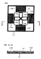
図4は、本実施形態に係るポインティングデバイス10の固定部材111および可動部材111のより詳細な構成図である。同図(a)は平面図であり、同図(b)は同図(a)中におけるA−A線での断面図である。ポインティングデバイス10は、側縁部が上方に突出した略板状の固定部材111と、この固定部材111に対して所定平面に平行な方向に移動可能な可動部材112と、固定部材111の側縁部と可動部材112との間に両者を連結する弾性部材115A〜115Dとを有する。弾性部材115A〜115Dそれぞれは、弾性を有する樹脂やバネなどであり、可動部材112の周囲の4個所に設けられており、一端が可動部材112に接合され、他端が固定部材111の側縁部に接合されている。
【0026】
また、可動部材112には4つのコイル116A〜116Dが固定されている。同図(a)の平面図において、中心を原点とし、右方向をX軸方向とし、上方向をY軸方向とすると、コイル116AはX座標値が正の領域にX軸をまたいで設けられており、コイル116BはX座標値が負の領域にX軸をまたいで設けられており、コイル116CはY座標値が正の領域にY軸をまたいで設けられており、また、コイル116DはY座標値が負の領域にY軸をまたいで設けられている。
【0027】
図5は、本実施形態に係るポインティングデバイス10における触刺激呈示機構を説明する平面図である。固定部材111には4つの磁石117A〜117Dが固定されている。磁石117Aは、X座標値が正であってY座標値も正である領域に、その磁束がコイル116Aおよび116Dの双方を貫くように設けられている。磁石117Bは、X座標値が負であってY座標値が正である領域に、その磁束がコイル116Bおよび116Dの双方を貫くように設けられている。磁石117Cは、X座標値が負であってY座標値も負である領域に、その磁束がコイル116Bおよび116Cの双方を貫くように設けられている。また、磁石117Dは、X座標値が正であってY座標値が負である領域に、その磁束がコイル116Aおよび116Cの双方を貫くように設けられている。これらのうち磁石117Aおよび117Cそれぞれは、可動部材112に対向する側がS極となるように配置され、磁石117Bおよび117Dそれぞれは、可動部材112に対向する側がN極となるように配置されている。
【0028】
コイル116A〜116Dと磁石117A〜117Dとの間の相対的な位置関係について換言すれば以下のとおりである。コイル116Aは、磁石117Aおよび117Dそれぞれが作る磁界に対して、X軸と平行な方向に電流が横切るように設けられている。コイル116Bは、磁石117Bおよび117Cそれぞれが作る磁界に対して、X軸と平行な方向に電流が横切るように設けられている。コイル116Cは、磁石117Cおよび117Dそれぞれが作る磁界に対して、Y軸と平行な方向に電流が横切るように設けられている。また、コイル116Dは、磁石117Aおよび117Bそれぞれが作る磁界に対して、Y軸と平行な方向に電流が横切るように設けられている。
【0029】
コイル116A〜116Dそれぞれは、銅線を用いてもよいし、また、軽量化のためにアルミニウム線を用いてもよく、さらに、銅メッキされたアルミニウム線を用いるのも好適である。磁石117A〜117Dそれぞれは、保磁力および残留磁束密度が大きいものが好ましく、例えばネオジ磁石が好適である。
【0030】
触刺激呈示手段151はコイル116A〜116Dそれぞれに対して独立に電流を流すことができる。そして、コイル116A〜116Dそれぞれに流れる電流の大きさ及び方向と、磁石117A〜117Dそれぞれが作る磁界との間で、フレミングの左手の法則に応じた相互作用が生じる。これに因り、コイル116A〜116Dそれぞれに推力が生じて、これらの推力と弾性部材115A〜115Dそれぞれの応力とに応じて、固定部材111に対して可動部材112が移動する。そして、この可動部材112により、可動部材112上に触れている操作者の指などに触刺激が呈示される。
【0031】
図6は、本実施形態に係るポインティングデバイス10における固定部材111と可動部材112との摺動機構を説明する断面図である。磁石117A〜117Dが固定された固定部材111の下面、および、コイル116A〜116Dが固定された可動部材112の上面それぞれに、両者が互いに摺動可能なように、摺動部材118Aおよび118Bが設けられている。摺動部材118Aおよび118Bそれぞれは、摩擦係数が小さいフッ素樹脂(例えばポリテトラフルオロエチレン)、潤滑油が含浸された樹脂および金属などが好適に用いられる。摺動部材118Aおよび118Bの間に、潤滑油を塗布するのも好適であり、また、非磁性体の球体を介在させて、この球体の転がりによって摺動させるようにしてもよい。
【0032】
なお、図6には、摺動機構だけでなく、可動部材112の上面にある表面層119、および、この表面層119の中央付近に設けられた感圧部120も示されている。図7は、本実施形態に係るポインティングデバイス10における感圧部120を説明する断面図である。表面層119は、人の指や掌などの受容器官が接離可能なように平坦に仕上げられている。感圧部120は、表面層119に人の指などが触れたことを検出するものである。感圧部120は、シリコーンゴムおよび導電性粉末を混合した材料を用いた感圧導電性ゴム120Aを導電性プラスティック層120Bおよび120Cで挟んだ構成となっている。そして、導電性プラスティック層120Bと導電性プラスティック層120Cとの間に電圧を印加し、感圧部120に人の指などが触れたときの接触圧に因る電気抵抗値の変化を検出して、これにより接触の有無を検出する。この感圧部120から出力される接触検出信号は触刺激呈示手段151に送られ、接触が確認されたときに可動部材112は触刺激呈示手段151により駆動される。
【0033】
この他、可動部材112に人の指などが接触したことを検出する方法として以下のものがある。すなわち、可動部材112に所定の電荷を蓄積して保持する電荷蓄積部を設け、人の指などが接触したときに電荷蓄積部に保持されていた電荷を人の指などに流出させ、電荷蓄積部に蓄積されている電荷の量の変化を検出することで、可動部材112に人の指などが接触したことを検出するのも好適である。また、可撓性を有する2つの電極を相互間距離が一定となるように支持し、人の指などが接触したときに、これら2つの電極の相互間距離が変化して両電極間に存在する静電容量が変化するのを検出することで、可動部材112に人の指などが接触したことを検出するのも好適である。さらに、可動部材112の上面に受光素子を設けるとともに、固定部材111の側縁部の上面にも受光素子を設け、各々の受光素子からの出力信号の値の変化に基づいて、可動部材112の上面の受光素子からの出力信号の値が低下したことを検出することで、可動部材112に人の指などが接触したことを検出するのも好適である。
【0034】
図8は、本実施形態に係るポインティングデバイス10における位置検出センサ114を説明する断面図である。位置検出センサ114は、固定部材111に固定された発光素子(例えば発光ダイオード)114Aおよび受光素子(例えばフォトダイオード)114B、ならびに、可動部材112の下面に描かれた光学模様(例えば、等間隔の濃淡模様、市松模様、など)114Cを含む。発光素子114Aから出射された光は光学模様114C上に照射され、光学模様114Cで反射された光は受光素子114Bにより受光される。受光素子114Bによる受光量は、発光素子114Aから出射された光が光学模様114C上に入射する位置における反射率に応じたものである。
【0035】
したがって、受光量に応じて受光素子114Bから出力される電気信号の変化に基づいて、固定部材111に対する可動部材112の変位量を検出することができる。また、このような位置検出センサ114をX軸方向およびY軸方向それぞれについて設けることにより、固定部材111に対する可動部材112の2次元的な変位量を検出することができる。この位置検出センサ114からの出力信号は第2の変位検出手段113に送られ、第2の変位検出手段113において、可動部材112の変位が検出される。
【0036】
この他、可動部材112の変位を検出する方法として以下のものがある。すなわち、可動部材112の下面に形成された細かい凹凸に対してレーザ光を照射してスペックル模様を生じさせ、このスペックル模様を2次元イメージセンサにより観察することで、固定部材111に対する可動部材112の2次元的な変位量を検出するのも好適である。また、可動部材112に接触する回転体を設け、この回転体の回転量をエンコーダにより検出することで、固定部材111に対する可動部材112の変位量を検出するのも好適である。さらに、固定部材111および可動部材112のうちの一方に発光素子を設け他方に2次元光学的位置検出素子(PSD: position sensitive detector)を設けることで、固定部材111に対する可動部材112の2次元的な変位量を検出するのも好適である。
【0037】
次に、ポインティングデバイス10の触刺激呈示動作について説明する。触刺激呈示手段151により駆動されてコイル116A〜116Dそれぞれに電流が流れると、フレミングの左手の法則に従って、コイル116A〜116Dそれぞれに推力が働き、これにより可動部材112が移動する。
【0038】
先ず、コイル116Aおよび116Bそれぞれについて考えると、固定部材111に垂直な方向であるZ軸方向に磁界が生じており、この磁界中にX軸方向に電流が流れると、Y軸方向への推力が生じる。コイル116Aに時計回りの方向に電流を流すと、コイル116Aには+Y軸方向の推力が働く。また、コイル116Bに反時計回りの方向に電流を流すと、コイル116Bには+Y軸方向の推力が働く。電流が流れる方向を変えることで推力が働く方向を変えることができ、また、電流値を変えることで推力の大きさを変えることができる。
【0039】
同様に、コイル116Cおよび116Dそれぞれについて考えると、固定部材111に垂直な方向であるZ軸方向に磁界が生じており、この磁界中にY軸方向に電流が流れると、X軸方向への推力が生じる。コイル116Cに時計回りの方向に電流を流すと、コイル116Cには+X軸方向の推力が働く。また、コイル116Dに反時計回りの方向に電流を流すと、コイル116Dには+X軸方向の推力が働く。電流が流れる方向を変えることで推力が働く方向を変えることができ、また、電流値を変えることで推力の大きさを変えることができる。
【0040】
固定部材111に対して可動部材112を平行移動させるだけでよい場合には、コイル116Aおよび116Bそれぞれを互いに結線して、コイル116Aおよび116Bそれぞれに同一方向の推力を与え、また、コイル116Cおよび116Dそれぞれを互いに結線して、コイル116Cおよび116Dそれぞれに同一方向の推力を与えればよい。
【0041】
また、Z軸をほぼ中心として固定部材111に対して可動部材112を回転させる方向に推力を生じさせることもできる。すなわち、コイル116Aおよびコイル116Bそれぞれに時計回りの方向に電流を流すと、コイル116Aには+Y軸方向の推力が働き、コイル116Bには−Y軸方向の推力が働くので、固定部材111に対して可動部材112を反時計回りの方向へ回転させる回転モーメントが生じる。コイル116Aおよびコイル116Bそれぞれに反時計回りの方向に電流を流すと、コイル116Aには−Y軸方向の推力が働き、コイル116Bには+Y軸方向の推力が働くので、固定部材111に対して可動部材112を時計回りの方向へ回転させる回転モーメントが生じる。また、コイル116Aおよびコイル116Bそれぞれに流れる電流の値の比を変えることで、回転中心を変えることができる。コイル116Cおよびコイル116Dそれぞれについても同様である。
【0042】
以上のような可動部材112の移動は、触刺激呈示手段151によりコイル116A〜116Dそれぞれに供給される電流により駆動される。また、この際の制御に際しては、例えば、位置偏差と位置偏差の微分量とに応じてなされるPD制御(比例・微分制御)が用いられる。図9は、本実施形態に係るポインティングデバイス10の可動部材112の動作例を説明する図である。同図(a)に示すように、可動部材112は、全体的には−Y軸方向に向かいつつ、左右に細かく振動している。同図(b)に示すように、可動部材112は、時計回り方向に平行移動で回転している。同図(c)に示すように、可動部材112は、時計回り方向に平行移動で回転しつ、その進行方向に対して左右に細かく振動している。また、同図(d)に示すように、可動部材112は、平行移動で揺動している。さらに、可動部材112は、「8」や「W」などの文字を描くような動きも可能である。また、可動部材112は、一定の速さの動きだけでなく、加速または減速を伴う動きも可能である。可動部材112の動きは、触刺激呈示手段151によりコイル116A〜116Dそれぞれに供給される電流に応じたものであって、可動部材112に人の指が軽く接触しているときには、その指は、この可動部材112の動きを感じ取ることができる。
【0043】
次に、ポインティングデバイス10の位置指定動作と表示部30におけるカーソル表示について図10を用いて説明する。表示部30の画面上に表示されるカーソル32の形状は、矢印形状のもの(同図(a))、指差形状のもの(同図(b),(c))、十字形状のもの(同図(d))、および、指先で掴む形状のもの(同図(e))、など、任意でよい。矢印形状のカーソル(同図(a))は、その矢印の先端で位置を示す。指差形状のカーソル(同図(b),(c))は、その指差の先端で位置を示す。十字形状のカーソル(同図(d))は、その十字の交点で位置を示す。また、指先で掴む形状のカーソル(同図(e))は、その掴む2本の指の中央で位置を示す。
【0044】
このとき、操作者がポインティングデバイス10の本体100を移動させると、その移動が第1の変位検出手段101により検出され、この検出された移動に応じて、表示部30の画面に設定される局所座標系の原点は変位し、カーソルは、その局所座標系の原点へ変位する。そして、操作者が本体100を固定したまま可動部材112を移動させると、固定部材111に対して可動部材112が変位し、この変位が第2の変位検出手段113により検出され、カーソルは、この検出された変位に応じた局所座標系上の位置へ更に変位する。
【0045】
また、表示部30の画面上に表示されるカーソル32の形状は、上記のものを組み合わせたものであるのが好適である。例えば、図10(f)に示すように、カーソル32の形状は、十字形状と指先で掴む形状とを組み合わせた形状であてもよい。この場合、十字形状の部分の十字の交点は、ポインティングデバイス10の第1の変位検出手段101により検出された本体100の変位に応じて表示部30の画面に設定される局所座標系の原点を示す。また、指先で掴む形状の部分の2本の指の中央は、ポインティングデバイス10の第2の変位検出手段113により検出された可動部材112の変位に応じて表示部30の画面に設定される局所座標系上の位置を示す。
【0046】
すなわち、操作者がポインティングデバイス10の本体100を移動させると、その移動が第1の変位検出手段101により検出され、この検出された移動に応じて、表示部30の画面上でカーソルの十字形状の部分は変位する。操作者が可動部材112を移動させておらず、固定部材111に対して可動部材112が所定の平衡位置にあれば、図10(f)に示すように、カーソルの指先で掴む形状の部分の2本の指の中央は、十字形状の部分の十字の交点と一致する。一方、操作者が可動部材112を移動させると、固定部材111に対して可動部材112が変位し、この変位が第2の変位検出手段113により検出され、この検出された変位に応じて、図10(g)に示すように、カーソルの指先で掴む形状の部分の2本の指の中央は、十字形状の部分の十字の交点に対して変位する。カーソルの指先で掴む形状の部分の2本の指の中央の位置は、位置指定手段141により指定される。
【0047】
なお、図10(a)〜(e)に示した単一形状のカーソルの表示と、図10(f)および(g)に示した2形状を組み合わせたカーソルの表示とは、操作者の選択により切り替えが可能であるのが好適である。
【0048】
また、可動部材112の変位量に対する局所座標系の原点から指定位置への変位量の割合は、本体100の変位量に対する局所座標系の原点の変位量の割合より小さいのが好適である。この場合、本体100を移動させることにより、表示部30の画面上の位置はマクロに変位し、可動部材112を移動させることにより、表示部30の画面上の位置はミクロに変位する。したがって、本体100の移動により表示部30の画面上の位置を粗く指定し、可動部材112の移動により表示部30の画面上の位置を細かく指定することができる。
【0049】
次に、ポインティングデバイス10の位置指定動作と触刺激呈示動作との関係について説明する。触刺激呈示手段151による可動部材112を介しての触刺激の呈示は、位置指定手段141により指定された表示部30の画面上の位置に応じてなされる。すなわち、情報処理装置1の本体40は触刺激生成手段を有しており、この触刺激生成手段は、ポインティングデバイス10の位置指定手段141により指定された表示部30の画面上の位置に応じた触刺激信号を生成して、この触刺激信号に基づいてポインティングデバイス10の触刺激呈示手段151に触刺激を呈示させる。
【0050】
例えば、表示部30の画面上にオブジェクトが表示されているときに、位置指定手段141により指定された表示部30の画面上の位置とオブジェクトとの間の距離が所定値以下である場合に、触刺激呈示手段151は、触刺激生成手段により生成された触刺激信号に従って可動部材112を振動させることにより、その旨を操作者に通知するようにしてもよい。また、この場合に、触刺激呈示手段151は、触刺激生成手段により生成された触刺激信号に従って可動部材112を強制的に移動させて、位置指定手段141による指定位置がオブジェクト上に来るようにしてもよい。さらに、位置指定手段141による指定位置がオブジェクト上に存在するときや移動するときに、触刺激呈示手段151は、触刺激生成手段により生成された触刺激信号に従って、可動部材112を介して、そのオブジェクトの属性に応じた触刺激を呈示してもよい。その他、ポインティングデバイス10の位置指定動作と触刺激呈示動作との関係には種々の態様があり得る。以下では具体的な実施例について説明する。
【0051】
第1実施例は、図11に示すように、表示部30の画面上に表示された複数のオブジェクトのうちの何れかのオブジェクトをポインティングデバイス10により選択するものである。この図に示す所謂ラジオボタンの如く、表示部30の画面上に表示されたオブジェクトが小さいと、従来のポインティングデバイスを用いたのでは、オブジェクトを選択するのは困難である。しかし、本実施形態に係る情報処理装置1およびポインティングデバイス10を用いる場合には、以下のような操作を行うことで、オブジェクトを容易に選択することができる。
【0052】
すなわち、操作者は、先ず、ポインティングデバイス10の本体100を移動させることで、選択しようとするオブジェクトの近くまでカーソルを移動させ、その後、ポインティングデバイス10の可動部材112を移動させることで、選択しようとするオブジェクトに向けてカーソルを移動させる。本体100の移動が腕や手首によるものであるのに対して、可動部材112の移動は指先によるものであるので、精度よく可動部材112を移動させることができる。また、本体10の移動によるカーソルのマクロな移動と比較して、可動部材112の移動によりミクロにカーソルを移動させることができる。したがって、オブジェクトにカーソルを重ねさせることが容易である。
【0053】
さらに、位置指定手段141による指定位置(表示部30の画面上のカーソル位置)がオブジェクト上に重なったときに、触刺激呈示手段151が可動部材112に触刺激(例えば振動)を呈示するようにしておけば、操作者は、画面を注視していなくても、カーソルがオブジェクトに重なったことを容易に認識することができる。或いは、操作者が本体100または可動部材112を移動させてカーソルをオブジェクトに近づけようとするときに、カーソルとオブジェクトとの距離が或る一定値以下になれば、触刺激呈示手段151が可動部材112を強制的に移動させて、位置指定手段141による指定位置(カーソル位置)がオブジェクト上に来るようにしておくのも好適である。そして、カーソル位置がオブジェクトに重なったときに、操作者は、可動部材112を指先で押下(クリック)することで、そのオブジェクトを選択することができる。
【0054】
なお、この場合には、情報処理装置1の本体40の触刺激生成手段は、ポインティングデバイス10の位置指定手段141により指定された表示部30の画面上の位置とオブジェクトと間の距離に応じて触刺激信号を生成して、この触刺激信号に基づいてポインティングデバイス10の触刺激呈示手段151は可動部材112を介して触刺激(振動または推力)を呈示する。
【0055】
第2実施例は、図12に示すように、ポインティングデバイス10の操作により、表示部30の画面上においてCADの操作を行うものである。表示部30の画面上に互いに嵌合し得る2つの図形要素AおよびBがあって、操作者は、ポインティングデバイス10を操作して、図形要素Bを移動させ、図形要素Bの凹部を図形要素Aの凸部に勘合させようとしている。このとき、従来のポインティングデバイスを用いると、図形要素Aと図形要素Bとを正確に勘合させることは困難であり、両者が重なったり或いは離れたりすることが多い。しかし、本実施形態に係る情報処理装置1およびポインティングデバイス10を用いる場合には、以下のような操作を行うことで、図形要素Aと図形要素Bとを正確に勘合させることができる。
【0056】
すなわち、操作者は、先ず、ポインティングデバイス10の本体100を移動させることで図形要素Bにカーソルを重ねさせ、可動部材112を押下してスイッチ131を押圧した状態のまま本体100を移動させることで図形要素Bを図形要素Aの近くまで移動させる。その後、可動部材112を押下してスイッチ131を押圧した状態のまま可動部材112を移動させることで、図形要素Bを図形要素Aに勘合させる。そして、両者が勘合した時点で、操作者は可動部材112の押下を止める。この実施例でも、本体100の移動が腕や手首によるものであるのに対して、可動部材112の移動は指先によるものであるので、精度よく可動部材112を移動させることができる。また、本体10の移動によるカーソルのマクロな移動と比較して、可動部材112の移動によりミクロにカーソルを移動させることができる。したがって、図形要素Aと図形要素Bとを容易に正確に勘合させることができる。
【0057】
また、図形要素Aと図形要素Bとが接したときに、触刺激呈示手段151が可動部材112に触刺激(例えば振動)を呈示するようにしておけば、操作者は、画面を注視していなくても、図形要素Aと図形要素Bとが接したことを容易に認識することができる。なお、この場合には、情報処理装置1の本体40の触刺激生成手段は、ポインティングデバイス10の位置指定手段141により指定された表示部30の画面上の位置にある図形要素Bと他の図形要素Aと間の距離に応じて触刺激信号を生成して、この触刺激信号に基づいてポインティングデバイス10の触刺激呈示手段151は可動部材112を介して触刺激(振動)を呈示する。
【0058】
さらに、操作者が本体100または可動部材112を移動させて図形要素Bを図形要素Aに近づけようとするときに、図形要素Bと図形要素Aとの距離が或る一定値以下になれば、表示部30の画面の表示を拡大させるのが好適である(同図(a)→(b))。このようにすることで、図形要素Aと図形要素Bとを更に容易に正確に勘合させることができる。なお、この場合には、情報処理装置1の本体40は表示態様変更手段を有しており、この表示態様変更手段は、移動対象である図形要素Bと他の図形要素Aとの間の距離に応じて、表示部30の画面の表示を拡大または縮小させる。そして、この表示部30の画面の表示態様の変更に応じて、操作者は、ポインティングデバイス10の本体100の移動による位置の指定と、可動部材112の移動による位置の指定とを切り替えることで、表示部30の画面上の位置を容易に指定することができる。
【0059】
第3実施例は、図13に示すように、ポインティングデバイス10の操作により、表示部30の画面に表示された球体を移動させるものである。この画面には各々の設定された重量が異なる3種類の球体が表示されている。操作者は、ポインティングデバイス10の本体100または可動部材112を移動させることで何れかの球体にカーソルを重ねさせ、可動部材112を押下してスイッチ131を押圧した後に可動部材112を移動させることで、その球体を持ち上げることができる。このとき、触刺激呈示手段151により、その持ち上げた球体の重量に応じた力が、可動部材112に置かれている指先に呈示される。
【0060】
なお、この場合には、情報処理装置1の本体40の触刺激生成手段は、ポインティングデバイス10の位置指定手段141により指定された表示部30の画面上の位置にある球体に設定された重量に応じた触刺激信号を生成して、この触刺激信号に基づいてポインティングデバイス10の触刺激呈示手段151は可動部材112を介して触刺激(反力)を呈示する。これにより、操作者は、可動部材112の移動により持ち上げた球体の重量を体感することができる。
【0061】
この第3実施例に類似のものとして、表示部30の画面上に粗滑分布を有するバックグラウンドが表示されていて、ポインティングデバイス10の可動部材112の移動によりバックグラウンド上でオブジェクトを移動させる場合の例が挙げられる。このとき、情報処理装置1の本体40の触刺激生成手段は、バックグラウンドのうちオブジェクトが存在する部分の粗滑に応じた触刺激信号を生成して、この触刺激信号に基づいてポインティングデバイス10の触刺激呈示手段151は可動部材112を介して触刺激(反力の変動)を呈示する。これにより、操作者は、可動部材112の移動により指定したオブジェクトの位置における粗滑を体感することができる。
【0062】
第4実施例は、図14に示すように、ポインティングデバイス10の操作により、表示部30の画面に表示された物品の表面の肌触りを体感するものである。インターネットのホームページや電子ショッピングモールなどにおいて商品の紹介がなされる場合があり、商品の形状や価格などの画像情報が提供される。しかし、商品(例えば、洋服やソファの生地、バッグの素材、壁紙など)によっては、触感覚も重要な情報である場合がある。このような場合、本実施形態に係るポインティングデバイス10を用いることにより、商品の触感覚の情報を得ることができる。
【0063】
すなわち、操作者は、先ず、興味ある商品の画像を表示部30の画面上に表示させる。そして、ポインティングデバイス10の本体100または可動部材112を移動させることで、その商品の画像にカーソルを重ねさせる。その後、可動部材112を移動させることで、その商品の画像上でカーソルを移動させる。このとき、触刺激呈示手段151により、その商品の肌触りに応じた力が、可動部材112に置かれている指先に呈示される。
【0064】
なお、この場合には、その商品の情報として、画面上に表示される画像の他、肌触りの属性情報が付加されている。情報処理装置1の本体40の触刺激生成手段は、ポインティングデバイス10の位置指定手段141により指定された表示部30の画面上の商品の情報に付加された属性情報に応じた触刺激信号を生成して、この触刺激信号に基づいてポインティングデバイス10の触刺激呈示手段151は可動部材112を介して触刺激を呈示する。これにより、操作者は、指先で可動部材112を移動させることで、指先で商品をなぞる行為と同等の行為を行うことができ、これと同時に、表示部30の画面に表示された商品の肌触りを指先で体感することができる。
【0065】
第5実施例は、図15に示すように、ポインティングデバイス10の操作により、表示部30の画面に表示された各種オブジェクトの属性を検知するものである。表示部30の画面に表示されるオブジェクトの種類として、例えば、アイコン、フォルダ、ファイルなどがある。本実施形態に係るポインティングデバイス10を用いれば、表示部30の画面に表示された各種オブジェクトの属性(種類、サイズ、名称、など)を把握することができる。
【0066】
すなわち、操作者は、先ず、ポインティングデバイス10の本体100または可動部材112を移動させることで、画面上の何れかのオブジェクト上にカーソルを移動させ、可動部材112を押下してスイッチ131を押圧する。そして、可動部材112を移動させることで、画面上のカーソルを移動させる。このとき、触刺激呈示手段151により、そのオブジェクトの属性に応じた触刺激が、可動部材112に置かれている指先に呈示される。例えば、オブジェクトの種類に応じて異なる触刺激を呈示するようにしてもよいし、オブジェクトがファイルである場合にファイルサイズに応じた大きさの反力を触刺激として呈示するようにしてもよい。
【0067】
また、画面上の何れかのオブジェクト上にカーソルが来たときに、触刺激呈示手段151により、そのオブジェクトの名称を表記するように可動部材112が移動するのも好適である。このようにすることで、可動部材112に置かれた指先は、可動部材112の動きを通じて、カーソルが位置するオブジェクトの名称を判読することができる。
【0068】
なお、この場合には、画面上に表示されるオブジェクトには、種類やサイズなどの属性情報が付加されている。情報処理装置1の本体40の触刺激生成手段は、ポインティングデバイス10の位置指定手段141により指定された表示部30の画面上のオブジェクトに付加された属性情報に応じた触刺激信号を生成して、この触刺激信号に基づいてポインティングデバイス10の触刺激呈示手段151は可動部材112を介して触刺激を呈示する。これにより、操作者は、画面上のオブジェクトの属性を容易に把握することができる。
【0069】
さらに、表示部30の画面上に表示されたオブジェクトに対して属性情報を付加することも、本実施形態に係るポインティングデバイス10を用いることにより可能である。すなわち、操作者は、先ず、メニューの所定の項目を選択して属性情報の付加が可能な状態にした後に、ポインティングデバイス10の本体100または可動部材112を移動させることで、画面上の何れかのオブジェクト上にカーソルを移動させ、可動部材112を押下してスイッチ131を押圧する。そして、可動部材112を移動させることで、画面上のカーソルを移動させる。このときの可動部材112の移動すなわちカーソルの移動が、触刺激呈示手段151により可動部材112を介して呈示される触刺激となる。
【0070】
例えば、画面上に文字情報を表示するオブジェクトにおいて、属性情報の付加が可能な状態にした後に、その文字をなぞるように可動部材112を移動させることで、そのオブジェクトに属性情報を付加する。その後、そのオブジェクト上にカーソルが来ると、触刺激呈示手段151により、そのオブジェクトの文字をなぞるように可動部材112が移動する。このようにすることで、可動部材112に置かれた指先は、可動部材112の動きを通じて、カーソルが位置するオブジェクトの文字を判読することができる。
【0071】
本発明は、上記実施形態に限定されるものではなく種々の変形が可能である。例えば、上記の実施形態のポインティングデバイス10は、マウス形状のものであって、基準面上のボール101の回転を検出することで本体100の変位を検出する接触回転式のものであったが、基準面の光学的な濃淡の変化を検出することで本体100の変位を検出する非接触光学式のものであってもよい。
【0072】
また、マウス形状のものでなくてもよく、ジョイスティック形状のものであってもよい。ジョイスティック形状のものである場合には、そのジョイスティックの先端に可動部材を設けて、この可動部材に触刺激を呈示するのが好適であり、このようにすることで、ジョイスティックを握った手の親指でこの可動部材を移動させることができ、この親指で触刺激を体感することができる。
【0073】
また、上記実施形態は触刺激を呈示するものであったが、他の刺激を呈示してもよく、例えば、光や音などの刺激を呈示してもよい。また、これらの刺激を選択または併用して呈示するようにしてもよい。
【0074】
さらに、上記実施形態では、変位検出部材は固定部材111に対して可動である可動部材112であって、第2の変位検出手段113は可動部材112の変位を検出するものであったが、これに限られない。例えば、ポインティングデバイス本体に対して変位検出部材が固定されていて、第2の変位検出手段は、この変位検出部材に接触する指等の変位を検出するようにしてもよい。具体的には、指等の接触に因る静電容量の変化に基づいて指等の変位を検出するトラックパッドにより実現することができる。
【0075】
【発明の効果】
以上、詳細に説明したとおり、本発明に係るポインティングデバイスによれば、このポインティングデバイスの本体の変位は第1の変位検出手段により検出され、変位検出部材の変位は第2の変位検出手段により検出される。位置指定手段により、第1の変位検出手段により検出された本体の変位および第2の変位検出手段により検出された変位検出部材の変位の双方に応じた位置が所定の空間に指定される。そして、刺激呈示手段により、位置指定手段により指定された所定の空間内の位置に応じた刺激が呈示される。
【0076】
このように、本発明に係るポインティングデバイスは、従来のマウスなどが有する本体の変位を検出する第1の変位検出手段に加えて、変位検出部材の変位を検出する第2の変位検出手段、第1および第2の変位検出手段それぞれにより検出された変位に基づいて所定の空間内に位置を指定する位置指定手段、および、この指定された位置に応じた刺激を呈示する刺激呈示手段を有していることで、所定の空間内の位置を容易に指定することができる。
【0077】
また、変位検出部材の変位量に対する局所座標系の原点から指定位置への変位量の割合は、本体の変位量に対する局所座標系の原点の変位量の割合より小さいのが好適である。この場合には、ポインティングデバイス本体の移動により所定の空間(表示部の画面)上の位置を粗く指定し、変位検出部材の移動により所定の空間(表示部の画面)上の位置を細かく指定することができるので、所定の空間内の位置を更に容易に指定することができる。
【0078】
また、変位検出部材が操作者の指により移動可能であるよう構成されているのが好適である。この場合には、ポインティングデバイス本体の移動が腕または手首によるものであるのに対して、変位検出部材の移動は指先によるものとなるので、精度よく変位検出部材を移動させることができので、所定の空間内の位置を更に容易に指定することができる。
【0079】
また、刺激呈示手段が変位検出部材を介して刺激を呈示するのが好適である。この場合には、操作者は、変位検出部材を移動させることで所定の空間内の位置を指定することができるとともに、この変位検出部材を介して刺激呈示手段により刺激が呈示される。変位検出部材が操作者の指により移動可能であることにより、操作者は、変位検出部材を介して、指先で物体をなぞる行為と同等の行為を行うことができ、これと同時に、その物体の肌触りを指先で体感することができる。
【0080】
本発明に係る情報処理装置によれば、表示部には、所定の空間が表示されるとともに、ポインティングデバイスにより指定された所定の空間内の位置も表示される。また、刺激生成手段により、ポインティングデバイスにより指定された所定の空間内の位置に応じた刺激信号が生成されて、この刺激信号に基づいてポインティングデバイスが刺激を呈示する。これにより、表示部に表示された所定の空間内の位置を容易に指定することができる。
【0081】
また、ポインティングデバイスにより指定された所定の空間内の位置に応じて表示部における所定の空間の表示の態様を変更する表示態様変更手段を更に備えるのが好適である。この場合には、表示態様変更手段により、表示部における所定の空間の表示の態様は、ポインティングデバイスにより指定された所定の空間内の位置に応じて変更される。そして、この表示部における所定の空間の表示の態様の変更に応じて、操作者は、ポインティングデバイス本体の移動による位置の指定と、変位検出部材の移動による位置の指定とを切り替えることで、表示部の画面上の位置を容易に指定することができる。
【図面の簡単な説明】
【図1】本実施形態に係る情報処理装置1の外観図である。
【図2】本実施形態に係るポインティングデバイス10の断面図である。
【図3】本実施形態に係るポインティングデバイス10のブロック図である。
【図4】本実施形態に係るポインティングデバイス10の固定部材111および可動部材111の構成図である。
【図5】本実施形態に係るポインティングデバイス10における触刺激呈示機構を説明する平面図である。
【図6】本実施形態に係るポインティングデバイス10における固定部材111と可動部材112との摺動機構を説明する断面図である。
【図7】本実施形態に係るポインティングデバイス10における感圧部120を説明する断面図である。
【図8】本実施形態に係るポインティングデバイス10における位置検出センサ114を説明する断面図である。
【図9】本実施形態に係るポインティングデバイス10の可動部材112の動作例を説明する図である。
【図10】本実施形態に係るポインティングデバイス10の位置指定動作と表示部30におけるカーソル表示について説明する図である。
【図11】第1実施例における表示部30の画面上の表示を示す図である。
【図12】第2実施例における表示部30の画面上の表示を示す図である。
【図13】第3実施例における表示部30の画面上の表示を示す図である。
【図14】第4実施例における表示部30の画面上の表示を示す図である。
【図15】第5実施例における表示部30の画面上の表示を示す図である。
【符号の説明】
1…情報処理装置、10…ポインティングデバイス、20…キーボード、30…表示部、40…本体、100…本体、101…ボール、101…第1の変位検出手段、111…固定部材、112…可動部材、113…第2の変位検出手段、114…位置検出センサ、115A〜115D…弾性部材、116A〜116D…コイル、117A〜117D…磁石、118A,118B…摺動部材、119…表面層、120…感圧部、121…支持部材、131…スイッチ、132…信号処理回路、141…位置指定手段、151…触刺激呈示手段。[0001]
BACKGROUND OF THE INVENTION
The present invention relates to a pointing device for designating a position in a predetermined space, and an information processing apparatus including the pointing device and a display unit.
[0002]
[Prior art]
In addition to a keyboard suitable for inputting characters, information processing apparatuses such as personal computers often have a pointing device suitable for designating a position on the screen in addition to a keyboard suitable for inputting characters. Yes. Examples of pointing devices include a mouse, a joystick, and a trackball. A displacement of the pointing device main body with respect to the reference plane is detected, and a cursor indicating a position on the screen moves in accordance with the detected displacement.
[0003]
In particular, a pointing device plays an important role in an information processing apparatus having a graphical user interface that depends on visual information displayed on a screen. For example, in order to select any one of a plurality of objects displayed on the screen, the pointing device is operated, the cursor is placed on the object to be selected, and the button attached to the pointing device. By pressing, a desired object can be easily selected.
[0004]
A pointing device having not only a function of specifying a position on the screen but also other functions has been proposed. For example, Japanese Laid-Open Patent Publication No. 1-102619 discloses a mouse with a digitizer function added to the upper surface of the mouse. In addition to designation, characters and the like are input by the digitizer function. In addition, what is disclosed in Japanese Patent Application Laid-Open No. 6-259189 uses a mouse original function to detect a displacement amount in a two-dimensional direction and designate a position on the screen, and also by a scrolling function added to the mouse. The display contents on the screen are scrolled. As described above, various proposals have been made for pointing devices to improve operability.
[0005]
[Problems to be solved by the invention]
However, the designation of the position on the screen by operating such a pointing device depends on the visual information on the screen, so it is not easy for a low vision person. In particular, when the object on the screen is small, it is not easy for not only a weak-sighted person but also a sighted person to specify the position on the screen by operating the pointing device. In addition, since the user is forced to keep an eye on the screen, it has an adverse effect on the operator's health (for example, eye strain and dry eyes). The pointing device disclosed in each of the above publications has other functions (digitizer function and scrolling function) added, but the position specifying function, which is the original function, has not been improved. The same applies to not only the designation of the position on the screen by the operation of the pointing device but also the interpretation of the attribute of the object on the screen at the position designated by the operation of the pointing device.
[0006]
The present invention has been made to solve the above-described problems, and an object thereof is to provide a pointing device and an information processing apparatus that can easily specify a position in a predetermined space.
[0007]
[Means for Solving the Problems]
The pointing device according to the present invention is a pointing device that designates a position in a predetermined space, and includes (1) first displacement detection means for detecting displacement of the main body, and (2) a displacement detection member, A second displacement detecting means for detecting the displacement of the displacement detecting member; and (3) displacing the origin of the local coordinate system in a predetermined space in accordance with the displacement of the main body detected by the first displacement detecting means, Position specifying means for designating a position displaced from the origin of the local coordinate system in accordance with the displacement of the displacement detecting member detected by the second displacement detecting means; and (4) within a predetermined space designated by the position designating means. And a stimulus presentation means for presenting a stimulus according to the position.
[0008]
The displacement of the main body of the pointing device is detected by the first displacement detection means, and the displacement of the displacement detection member is detected by the second displacement detection means. According to the displacement of the main body detected by the first displacement detection means, the origin of the local coordinate system in the predetermined space is displaced by the position designation means, and the displacement detection member detected by the second displacement detection means A position displaced from the origin of the local coordinate system is designated according to the displacement. That is, a position corresponding to both the displacement of the main body detected by the first displacement detection means and the displacement of the displacement detection member detected by the second displacement detection means is designated as the predetermined space. Then, a stimulus (preferably a tactile stimulus) corresponding to the position in the predetermined space designated by the position designating unit is presented by the stimulus presenting unit.
[0009]
The pointing device according to the present invention can have substantially the same form as a conventional mouse or joystick. The pointing device according to the present invention includes a second displacement detecting means for detecting the displacement of the displacement detecting member, in addition to the first displacement detecting means for detecting the displacement of the main body of the conventional mouse or the like, There is provided position specifying means for specifying a position in a predetermined space based on the displacement detected by each of the second displacement detecting means, and stimulus presenting means for presenting a stimulus corresponding to the designated position. . There can be various modes of presenting the stimulus by the stimulus presenting means. By doing in this way, the position in a predetermined space can be specified easily.
[0010]
When a pointing device is used together with an information processing apparatus having a display unit, the predetermined space is a display space on the screen of the display unit, and a cursor is placed at a position on the screen specified by the position specifying unit. Is displayed. The predetermined space does not necessarily have to be visually recognized, and may be virtually set.
[0011]
In the pointing device according to the present invention, the ratio of the displacement amount from the origin of the local coordinate system to the designated position with respect to the displacement amount of the displacement detection member is smaller than the ratio of the displacement amount of the origin of the local coordinate system to the displacement amount of the main body. Is preferred. In this case, by moving the pointing device main body, the position on the predetermined space (screen of the display unit) is displaced macroscopically, and by moving the displacement detection member, the predetermined space (screen of the display unit) The upper position is displaced microscopically. Therefore, the position on the predetermined space (display unit screen) can be specified roughly by moving the pointing device body, and the position on the predetermined space (display unit screen) can be specified finely by moving the displacement detection member. . By doing in this way, the position in the predetermined space can be specified more easily.
[0012]
The pointing device according to the present invention is preferably configured such that the displacement detection member can be moved by an operator's finger. In this case, the movement of the pointing device main body is performed by the arm or the wrist, whereas the movement of the displacement detection member is performed by the fingertip, so that the displacement detection member can be moved with high accuracy. In this way, the position in the predetermined space can be specified more easily.
[0013]
In the pointing device according to the present invention, it is preferable that the stimulus presenting means presents the stimulus via the displacement detection member. In this case, the operator can designate a position in a predetermined space by moving the displacement detection member, and the stimulus is presented by the stimulus presenting means via the displacement detection member. Since the displacement detection member can be moved by the operator's finger, the operator can perform an action equivalent to the action of tracing the object with the fingertip via the displacement detection member. You can feel the touch with your fingertips.
[0014]
An information processing apparatus according to the present invention includes: (1) a pointing device according to the present invention that specifies a position in a predetermined space and presents a stimulus; and (2) displays the predetermined space and is displayed by the pointing device. A display unit that also displays a position in a specified space, and (3) a stimulation signal corresponding to the position in the predetermined space specified by the pointing device is generated, and the pointing device is generated based on the stimulation signal. And a stimulus generation means for presenting the stimulus.
[0015]
According to this information processing apparatus, a predetermined space is displayed on the display unit, and a position in the predetermined space designated by the pointing device is also displayed. Further, a stimulus signal corresponding to a position in a predetermined space designated by the pointing device is generated by the stimulus generating means, and the pointing device presents a stimulus based on the stimulus signal.
[0016]
Moreover, it is preferable that the information processing apparatus according to the present invention further includes a display mode changing unit that changes a display mode of the predetermined space on the display unit according to a position in the predetermined space designated by the pointing device. is there. In this case, the display mode changing unit changes the display mode of the predetermined space on the display unit in accordance with the position in the predetermined space designated by the pointing device. For example, the display of a predetermined space on the display unit is enlarged or reduced according to the relative positional relationship between the position designated by the pointing device and the object. Then, according to the change in the display mode of the predetermined space in the display unit, the operator switches between designation of the position by movement of the pointing device body and designation of the position by movement of the displacement detection member, The position of the part on the screen can be easily specified.
[0017]
DETAILED DESCRIPTION OF THE INVENTION
Hereinafter, embodiments of the present invention will be described in detail with reference to the accompanying drawings. In the description of the drawings, the same elements are denoted by the same reference numerals, and redundant description is omitted.
[0018]
First, configurations of an information processing apparatus and a pointing device according to the present embodiment will be described with reference to FIGS. FIG. 1 is an external view of an information processing apparatus 1 according to the present embodiment. The information processing apparatus 1 includes a
[0019]
FIG. 2 is a cross-sectional view of the
[0020]
The
[0021]
Further, the
[0022]
FIG. 3 is a block diagram of the
[0023]
The
[0024]
Information on the position to be finally specified may be transmitted from the
[0025]
FIG. 4 is a more detailed configuration diagram of the fixed
[0026]
Further, four coils 116 </ b> A to 116 </ b> D are fixed to the
[0027]
FIG. 5 is a plan view for explaining a tactile stimulus presentation mechanism in the
[0028]
In other words, the relative positional relationship between the
[0029]
Each of the coils 116 </ b> A to 116 </ b> D may use a copper wire, may use an aluminum wire for weight reduction, and further preferably uses a copper-plated aluminum wire. Each of the
[0030]
The tactile stimulus presenting means 151 can flow a current independently to each of the
[0031]
FIG. 6 is a cross-sectional view illustrating a sliding mechanism between the fixed
[0032]
FIG. 6 shows not only the sliding mechanism but also the
[0033]
In addition, there are the following methods for detecting that a human finger or the like has contacted the
[0034]
FIG. 8 is a cross-sectional view for explaining the
[0035]
Therefore, the amount of displacement of the
[0036]
Other methods for detecting the displacement of the
[0037]
Next, the tactile stimulus presenting operation of the
[0038]
First, considering each of the
[0039]
Similarly, when considering each of the
[0040]
When it is only necessary to translate the
[0041]
In addition, a thrust can be generated in a direction in which the
[0042]
The movement of the
[0043]
Next, the position specifying operation of the
[0044]
At this time, when the operator moves the
[0045]
The shape of the
[0046]
That is, when the operator moves the
[0047]
It should be noted that the display of the single shape cursor shown in FIGS. 10A to 10E and the display of the cursor combining the two shapes shown in FIGS. 10F and 10G are selected by the operator. It is preferable that switching is possible.
[0048]
The ratio of the displacement amount from the origin of the local coordinate system to the designated position with respect to the displacement amount of the
[0049]
Next, the relationship between the position designation operation of the
[0050]
For example, when an object is displayed on the screen of the
[0051]
In the first embodiment, as shown in FIG. 11, any one of a plurality of objects displayed on the screen of the
[0052]
That is, the operator first moves the
[0053]
Further, when the position designated by the position designation unit 141 (cursor position on the screen of the display unit 30) overlaps the object, the tactile
[0054]
In this case, the tactile stimulus generation means of the
[0055]
In the second embodiment, the CAD is operated on the screen of the
[0056]
That is, the operator first moves the
[0057]
Further, when the graphic element A and the graphic element B come into contact with each other, if the tactile stimulus presenting means 151 presents a tactile stimulus (for example, vibration) to the
[0058]
Further, when the operator moves the
[0059]
As shown in FIG. 13, the third embodiment moves a sphere displayed on the screen of the
[0060]
In this case, the tactile stimulus generating means of the
[0061]
Similar to the third embodiment, when a background having a coarse distribution is displayed on the screen of the
[0062]
In the fourth embodiment, as shown in FIG. 14, a touch of the surface of an article displayed on the screen of the
[0063]
That is, the operator first displays an image of a product of interest on the screen of the
[0064]
In this case, touch attribute information is added as the product information in addition to the image displayed on the screen. The tactile stimulus generating means of the
[0065]
As shown in FIG. 15, the fifth embodiment detects attributes of various objects displayed on the screen of the
[0066]
That is, the operator first moves the
[0067]
In addition, when the cursor comes over any object on the screen, it is also preferable that the
[0068]
In this case, attribute information such as type and size is added to the object displayed on the screen. The tactile stimulus generating means of the
[0069]
Furthermore, it is possible to add attribute information to an object displayed on the screen of the
[0070]
For example, in an object that displays character information on the screen, after the attribute information can be added, the
[0071]
The present invention is not limited to the above embodiment, and various modifications can be made. For example, the
[0072]
Moreover, it does not have to be a mouse shape and may be a joystick shape. In the case of a joystick shape, it is preferable to provide a movable member at the tip of the joystick and present a tactile stimulus to the movable member, and in this way, the thumb of the hand holding the joystick Thus, the movable member can be moved, and a tactile stimulus can be experienced with the thumb.
[0073]
Moreover, although the said embodiment presented tactile stimuli, you may present other stimuli, for example, stimuli, such as light and a sound, may be presented. These stimuli may be selected or used in combination.
[0074]
Furthermore, in the above embodiment, the displacement detection member is the
[0075]
【The invention's effect】
As described above in detail, according to the pointing device of the present invention, the displacement of the main body of the pointing device is detected by the first displacement detecting means, and the displacement of the displacement detecting member is detected by the second displacement detecting means. Is done. The position designation means designates a position corresponding to both the displacement of the main body detected by the first displacement detection means and the displacement of the displacement detection member detected by the second displacement detection means in a predetermined space. And the stimulus according to the position in the predetermined space designated by the position designation means is presented by the stimulus presentation means.
[0076]
As described above, the pointing device according to the present invention includes, in addition to the first displacement detection means for detecting the displacement of the main body of the conventional mouse or the like, the second displacement detection means for detecting the displacement of the displacement detection member, There are provided position specifying means for specifying a position in a predetermined space based on the displacement detected by each of the first and second displacement detecting means, and stimulus presenting means for presenting a stimulus corresponding to the designated position. Therefore, it is possible to easily specify a position in a predetermined space.
[0077]
The ratio of the displacement amount from the origin of the local coordinate system to the designated position with respect to the displacement amount of the displacement detection member is preferably smaller than the ratio of the displacement amount of the origin of the local coordinate system to the displacement amount of the main body. In this case, the position on the predetermined space (display unit screen) is roughly specified by the movement of the pointing device main body, and the position on the predetermined space (display unit screen) is finely specified by the movement of the displacement detection member. Therefore, the position in the predetermined space can be specified more easily.
[0078]
In addition, it is preferable that the displacement detection member is configured to be movable by an operator's finger. In this case, the movement of the pointing device main body is performed by the arm or the wrist, whereas the movement of the displacement detection member is performed by the fingertip. Therefore, the displacement detection member can be moved with high accuracy. The position in the space can be specified more easily.
[0079]
Further, it is preferable that the stimulus presenting means presents the stimulus via the displacement detection member. In this case, the operator can designate a position in a predetermined space by moving the displacement detection member, and the stimulus is presented by the stimulus presenting means via the displacement detection member. Since the displacement detection member can be moved by the operator's finger, the operator can perform an action equivalent to the action of tracing the object with the fingertip via the displacement detection member. You can feel the touch with your fingertips.
[0080]
According to the information processing apparatus of the present invention, a predetermined space is displayed on the display unit, and a position in the predetermined space designated by the pointing device is also displayed. Further, a stimulus signal corresponding to a position in a predetermined space designated by the pointing device is generated by the stimulus generating means, and the pointing device presents a stimulus based on the stimulus signal. Thereby, the position in the predetermined space displayed on the display unit can be easily specified.
[0081]
Moreover, it is preferable to further include display mode changing means for changing the display mode of the predetermined space on the display unit in accordance with the position in the predetermined space designated by the pointing device. In this case, the display mode changing unit changes the display mode of the predetermined space on the display unit in accordance with the position in the predetermined space designated by the pointing device. Then, according to the change in the display mode of the predetermined space in the display unit, the operator switches between designation of the position by movement of the pointing device body and designation of the position by movement of the displacement detection member, The position of the part on the screen can be easily specified.
[Brief description of the drawings]
FIG. 1 is an external view of an information processing apparatus 1 according to an embodiment.
FIG. 2 is a cross-sectional view of the
FIG. 3 is a block diagram of the
FIG. 4 is a configuration diagram of a fixed
FIG. 5 is a plan view illustrating a tactile stimulus presentation mechanism in the
FIG. 6 is a cross-sectional view illustrating a sliding mechanism between a
FIG. 7 is a cross-sectional view illustrating a pressure
FIG. 8 is a cross-sectional view illustrating a
FIG. 9 is a diagram illustrating an operation example of the
FIG. 10 is a diagram illustrating a position specifying operation of the pointing device and a cursor display on the
FIG. 11 is a diagram showing a display on the screen of the
12 is a diagram showing a display on the screen of the
FIG. 13 is a diagram showing a display on the screen of the
FIG. 14 is a diagram showing a display on the screen of the
FIG. 15 is a diagram showing a display on the screen of the
[Explanation of symbols]
DESCRIPTION OF SYMBOLS 1 ... Information processing apparatus, 10 ... Pointing device, 20 ... Keyboard, 30 ... Display part, 40 ... Main body, 100 ... Main body, 101 ... Ball, 101 ... First displacement detection means, 111 ... Fixed member, 112 ... Movable member , 113 ... second displacement detection means, 114 ... position detection sensor, 115A to 115D ... elastic member, 116A to 116D ... coil, 117A to 117D ... magnet, 118A, 118B ... sliding member, 119 ... surface layer, 120 ...
Claims (6)
本体の変位を検出する第1の変位検出手段と、
変位検出部材を有し、この変位検出部材の変位を検出する第2の変位検出手段と、
前記第1の変位検出手段により検出された本体の変位に応じて前記所定の空間内の局所座標系の原点を変位させ、前記第2の変位検出手段により検出された前記変位検出部材の変位に応じて前記局所座標系の原点から変位した位置を指定する位置指定手段と、
前記位置指定手段により指定された前記所定の空間内の位置に応じた刺激を呈示する刺激呈示手段と、
を備えることを特徴とするポインティングデバイス。A pointing device for designating a position in a predetermined space,
First displacement detection means for detecting displacement of the main body;
A second displacement detecting means having a displacement detecting member and detecting the displacement of the displacement detecting member;
The origin of the local coordinate system in the predetermined space is displaced according to the displacement of the main body detected by the first displacement detecting means, and the displacement of the displacement detecting member detected by the second displacement detecting means is detected. In response, position specifying means for specifying a position displaced from the origin of the local coordinate system;
Stimulus presentation means for presenting a stimulus according to a position in the predetermined space designated by the position designation means;
A pointing device comprising:
前記所定の空間を表示するとともに、前記ポインティングデバイスにより指定された前記所定の空間内の位置をも表示する表示部と、
前記ポインティングデバイスにより指定された前記所定の空間内の位置に応じた刺激信号を生成して、この刺激信号に基づいて前記ポインティングデバイスに刺激を呈示させる刺激生成手段と、
を備えることを特徴とする情報処理装置。The pointing device according to claim 1, wherein the pointing device designates a position in a predetermined space and presents a stimulus.
A display unit that displays the predetermined space and also displays a position in the predetermined space designated by the pointing device;
Stimulus generating means for generating a stimulus signal corresponding to a position in the predetermined space designated by the pointing device and causing the pointing device to present a stimulus based on the stimulus signal;
An information processing apparatus comprising:
Priority Applications (2)
| Application Number | Priority Date | Filing Date | Title |
|---|---|---|---|
| JP2000189651A JP4013454B2 (en) | 2000-06-23 | 2000-06-23 | Pointing device and information processing apparatus |
| US09/843,811 US6618037B2 (en) | 2000-06-23 | 2001-04-30 | Pointing device and information processing apparatus |
Applications Claiming Priority (1)
| Application Number | Priority Date | Filing Date | Title |
|---|---|---|---|
| JP2000189651A JP4013454B2 (en) | 2000-06-23 | 2000-06-23 | Pointing device and information processing apparatus |
Publications (2)
| Publication Number | Publication Date |
|---|---|
| JP2002007065A JP2002007065A (en) | 2002-01-11 |
| JP4013454B2 true JP4013454B2 (en) | 2007-11-28 |
Family
ID=18689256
Family Applications (1)
| Application Number | Title | Priority Date | Filing Date |
|---|---|---|---|
| JP2000189651A Expired - Lifetime JP4013454B2 (en) | 2000-06-23 | 2000-06-23 | Pointing device and information processing apparatus |
Country Status (2)
| Country | Link |
|---|---|
| US (1) | US6618037B2 (en) |
| JP (1) | JP4013454B2 (en) |
Families Citing this family (23)
| Publication number | Priority date | Publication date | Assignee | Title |
|---|---|---|---|---|
| US7084854B1 (en) | 2000-09-28 | 2006-08-01 | Immersion Corporation | Actuator for providing tactile sensations and device for directional tactile sensations |
| US7202851B2 (en) * | 2001-05-04 | 2007-04-10 | Immersion Medical Inc. | Haptic interface for palpation simulation |
| JP2003008693A (en) * | 2001-06-21 | 2003-01-10 | Nec Access Technica Ltd | Portable telephone |
| JP2003323256A (en) * | 2002-04-26 | 2003-11-14 | Fuji Xerox Co Ltd | Information processing device |
| US8054291B2 (en) * | 2003-01-20 | 2011-11-08 | Asahi Kasei Emd Corporation | Pointing device |
| US7221356B2 (en) * | 2004-02-26 | 2007-05-22 | Microsoft Corporation | Data input device and method for detecting an off-surface condition by a laser speckle size characteristic |
| FR2877113B1 (en) * | 2004-10-22 | 2007-05-11 | Commissariat Energie Atomique | AUTONOMOUS DEVICE, SYSTEM AND METHOD FOR NAVIGATION IN A SPACE OF AT LEAST THREE DIMENSIONS. |
| US20060132440A1 (en) * | 2004-12-22 | 2006-06-22 | Max Safai | Mouse input device with secondary input device |
| EP1715406A1 (en) * | 2005-04-23 | 2006-10-25 | STMicroelectronics (Research & Development) Limited | Pointing device and method of operating such a pointing device |
| JP4684794B2 (en) * | 2005-08-04 | 2011-05-18 | 富士通コンポーネント株式会社 | Operation device, electronic book apparatus, and electronic apparatus |
| DE102007009389A1 (en) * | 2007-02-20 | 2008-08-21 | Bizerba Gmbh & Co. Kg | Force measuring device and method for signal evaluation |
| JP5302610B2 (en) * | 2008-10-01 | 2013-10-02 | キヤノン株式会社 | Information processing apparatus and information processing method |
| US8542105B2 (en) | 2009-11-24 | 2013-09-24 | Immersion Corporation | Handheld computer interface with haptic feedback |
| US20150379880A1 (en) * | 2014-03-06 | 2015-12-31 | Maneesh SETHI | Device for training behavior |
| US20150254992A1 (en) * | 2014-03-06 | 2015-09-10 | Maneesh SETHI | Memory-enhancing and habit-training methods and devices |
| US20160063890A1 (en) * | 2014-03-06 | 2016-03-03 | Maneesh SETHI | Method for training behavior |
| CN206643787U (en) * | 2016-01-07 | 2017-11-17 | 昭和电工气体产品株式会社 | Peener annex and peener |
| US10372155B2 (en) | 2017-08-20 | 2019-08-06 | Pixart Imaging Inc. | Joystick and related control method |
| US10969878B2 (en) * | 2017-08-20 | 2021-04-06 | Pixart Imaging Inc. | Joystick with light emitter and optical sensor within internal chamber |
| JP2019128738A (en) * | 2018-01-23 | 2019-08-01 | 東京瓦斯株式会社 | Product sales system and product purchase supporting device |
| WO2020149120A1 (en) * | 2019-01-17 | 2020-07-23 | アルプスアルパイン株式会社 | Input device and operation unit |
| CN111840993B (en) * | 2019-04-25 | 2023-12-05 | 原相科技股份有限公司 | game joystick |
| KR20230090895A (en) * | 2021-12-15 | 2023-06-22 | 현대자동차주식회사 | Portable operating force measuring device |
Family Cites Families (8)
| Publication number | Priority date | Publication date | Assignee | Title |
|---|---|---|---|---|
| NL8602624A (en) | 1986-10-20 | 1988-05-16 | Oce Nederland Bv | INPUT DEVICE WITH TAKTILE FEEDBACK. |
| JPH01102619A (en) | 1987-10-16 | 1989-04-20 | Canon Inc | Information input device |
| US5374942A (en) | 1993-02-05 | 1994-12-20 | Gilligan; Federico G. | Mouse and method for concurrent cursor position and scrolling control |
| CN1074843C (en) * | 1996-03-20 | 2001-11-14 | 陈美雍 | Cursor Positioning Device |
| US6072469A (en) * | 1996-06-20 | 2000-06-06 | Chen; Mei-Yun | Cursor positioning device for computer system |
| US6121955A (en) * | 1997-08-06 | 2000-09-19 | Primax Electronics Ltd. | Computer joystick having two optical sensors for generating vector signals |
| US5959614A (en) * | 1997-09-30 | 1999-09-28 | Primax Electronics Ltd. | Pointing control system for controlling rotations of an object within a three dimensional view |
| JP3341661B2 (en) * | 1997-12-10 | 2002-11-05 | 株式会社村田製作所 | Vibrating gyro |
-
2000
- 2000-06-23 JP JP2000189651A patent/JP4013454B2/en not_active Expired - Lifetime
-
2001
- 2001-04-30 US US09/843,811 patent/US6618037B2/en not_active Expired - Fee Related
Also Published As
| Publication number | Publication date |
|---|---|
| US6618037B2 (en) | 2003-09-09 |
| US20010055001A1 (en) | 2001-12-27 |
| JP2002007065A (en) | 2002-01-11 |
Similar Documents
| Publication | Publication Date | Title |
|---|---|---|
| JP4013454B2 (en) | Pointing device and information processing apparatus | |
| JP7787932B2 (en) | Finger-mounted device using sensors and tactile sensations | |
| JP3543695B2 (en) | Driving force generator | |
| JP3069791U (en) | Mouse and positioning device | |
| EP2702468B1 (en) | Electro-vibrotactile display | |
| KR20160003031A (en) | Simulation of tangible user interface interactions and gestures using array of haptic cells | |
| JP2002229731A (en) | Input device and electronic device | |
| KR101524906B1 (en) | Apparatus for generating tactile sensation, dielectricpolymer high-perpormance driver, actuator, interfacing apparatus, apparatus for providing tactile feedback using the same | |
| JP2017097438A (en) | Tactile providing device and tactile providing system | |
| JP4168752B2 (en) | Information sensing device, information transmission system, and storage medium storing program for controlling information sensing device | |
| JP4244784B2 (en) | Driving force generator | |
| JP3956971B2 (en) | Information processing apparatus, information processing method, and recording medium | |
| EP1594043A2 (en) | Information input device and information input method | |
| JP2003323256A (en) | Information processing device | |
| JP2002149339A (en) | Information processor, information processing method and recording medium | |
| JP3982328B2 (en) | Information processing system | |
| JP3937925B2 (en) | Information processing system and information processing method | |
| JP4140268B2 (en) | Information processing system and information processing method | |
| Kuribara et al. | Mouse Augmentation Using a Malleable Mouse Pad | |
| JP5860009B2 (en) | Interface device | |
| JPH087523B2 (en) | Simulated tactile presentation device | |
| KR20030084581A (en) | Information processing system and information processing method | |
| JP2003108307A (en) | Input/output device |
Legal Events
| Date | Code | Title | Description |
|---|---|---|---|
| A621 | Written request for application examination |
Free format text: JAPANESE INTERMEDIATE CODE: A621 Effective date: 20040115 |
|
| A977 | Report on retrieval |
Free format text: JAPANESE INTERMEDIATE CODE: A971007 Effective date: 20060420 |
|
| A131 | Notification of reasons for refusal |
Free format text: JAPANESE INTERMEDIATE CODE: A131 Effective date: 20070522 |
|
| TRDD | Decision of grant or rejection written | ||
| A01 | Written decision to grant a patent or to grant a registration (utility model) |
Free format text: JAPANESE INTERMEDIATE CODE: A01 Effective date: 20070821 |
|
| A61 | First payment of annual fees (during grant procedure) |
Free format text: JAPANESE INTERMEDIATE CODE: A61 Effective date: 20070903 |
|
| FPAY | Renewal fee payment (event date is renewal date of database) |
Free format text: PAYMENT UNTIL: 20100921 Year of fee payment: 3 |
|
| R150 | Certificate of patent or registration of utility model |
Free format text: JAPANESE INTERMEDIATE CODE: R150 Ref document number: 4013454 Country of ref document: JP Free format text: JAPANESE INTERMEDIATE CODE: R150 |
|
| FPAY | Renewal fee payment (event date is renewal date of database) |
Free format text: PAYMENT UNTIL: 20110921 Year of fee payment: 4 |
|
| FPAY | Renewal fee payment (event date is renewal date of database) |
Free format text: PAYMENT UNTIL: 20120921 Year of fee payment: 5 |
|
| FPAY | Renewal fee payment (event date is renewal date of database) |
Free format text: PAYMENT UNTIL: 20120921 Year of fee payment: 5 |
|
| FPAY | Renewal fee payment (event date is renewal date of database) |
Free format text: PAYMENT UNTIL: 20130921 Year of fee payment: 6 |
|
| EXPY | Cancellation because of completion of term |