JP4005426B2 - Tow truck connector - Google Patents
Tow truck connector Download PDFInfo
- Publication number
- JP4005426B2 JP4005426B2 JP2002191960A JP2002191960A JP4005426B2 JP 4005426 B2 JP4005426 B2 JP 4005426B2 JP 2002191960 A JP2002191960 A JP 2002191960A JP 2002191960 A JP2002191960 A JP 2002191960A JP 4005426 B2 JP4005426 B2 JP 4005426B2
- Authority
- JP
- Japan
- Prior art keywords
- terminal
- wire harness
- connection
- vehicle
- connection body
- Prior art date
- Legal status (The legal status is an assumption and is not a legal conclusion. Google has not performed a legal analysis and makes no representation as to the accuracy of the status listed.)
- Expired - Lifetime
Links
Images


Classifications
-
- H—ELECTRICITY
- H01—ELECTRIC ELEMENTS
- H01R—ELECTRICALLY-CONDUCTIVE CONNECTIONS; STRUCTURAL ASSOCIATIONS OF A PLURALITY OF MUTUALLY-INSULATED ELECTRICAL CONNECTING ELEMENTS; COUPLING DEVICES; CURRENT COLLECTORS
- H01R13/00—Details of coupling devices of the kinds covered by groups H01R12/70 or H01R24/00 - H01R33/00
- H01R13/46—Bases; Cases
- H01R13/52—Dustproof, splashproof, drip-proof, waterproof, or flameproof cases
- H01R13/5202—Sealing means between parts of housing or between housing part and a wall, e.g. sealing rings
-
- H—ELECTRICITY
- H01—ELECTRIC ELEMENTS
- H01R—ELECTRICALLY-CONDUCTIVE CONNECTIONS; STRUCTURAL ASSOCIATIONS OF A PLURALITY OF MUTUALLY-INSULATED ELECTRICAL CONNECTING ELEMENTS; COUPLING DEVICES; CURRENT COLLECTORS
- H01R11/00—Individual connecting elements providing two or more spaced connecting locations for conductive members which are, or may be, thereby interconnected, e.g. end pieces for wires or cables supported by the wire or cable and having means for facilitating electrical connection to some other wire, terminal, or conductive member, blocks of binding posts
- H01R11/11—End pieces or tapping pieces for wires, supported by the wire and for facilitating electrical connection to some other wire, terminal or conductive member
- H01R11/12—End pieces terminating in an eye, hook, or fork
-
- H—ELECTRICITY
- H01—ELECTRIC ELEMENTS
- H01R—ELECTRICALLY-CONDUCTIVE CONNECTIONS; STRUCTURAL ASSOCIATIONS OF A PLURALITY OF MUTUALLY-INSULATED ELECTRICAL CONNECTING ELEMENTS; COUPLING DEVICES; CURRENT COLLECTORS
- H01R13/00—Details of coupling devices of the kinds covered by groups H01R12/70 or H01R24/00 - H01R33/00
- H01R13/46—Bases; Cases
- H01R13/52—Dustproof, splashproof, drip-proof, waterproof, or flameproof cases
- H01R13/5213—Covers
-
- H—ELECTRICITY
- H01—ELECTRIC ELEMENTS
- H01R—ELECTRICALLY-CONDUCTIVE CONNECTIONS; STRUCTURAL ASSOCIATIONS OF A PLURALITY OF MUTUALLY-INSULATED ELECTRICAL CONNECTING ELEMENTS; COUPLING DEVICES; CURRENT COLLECTORS
- H01R13/00—Details of coupling devices of the kinds covered by groups H01R12/70 or H01R24/00 - H01R33/00
- H01R13/46—Bases; Cases
- H01R13/52—Dustproof, splashproof, drip-proof, waterproof, or flameproof cases
- H01R13/5216—Dustproof, splashproof, drip-proof, waterproof, or flameproof cases characterised by the sealing material, e.g. gels or resins
Landscapes
- Connector Housings Or Holding Contact Members (AREA)
- Manufacturing Of Electrical Connectors (AREA)
Description
【0001】
【発明の属する技術分野】
この発明は、牽引車用コネクタ及びそれに関連する技術に関する。
【0002】
【従来の技術】
牽引車において、トレーラー等の被牽引対象と車両本体との間を電気的に接続するいわゆるトーイングヒッチ用の自動車用ワイヤーハーネスに使用される車両本体側のコネクタは、市場での一般ユーザーが準備するトレーラー側のワイヤーハーネスと電気接続できるように、形状・寸法がSAE(米国自動車技術者協会)規格またはJIS(日本規格協会)規格等によって規格化されており、様々な車種間の互換性を確保している。また、例えば米国内においては、幾つかのメーカーが市販している「7-Way Connector」が事実上の業界標準となっている。
【0003】
この「7-Way Connector」は、トレーラー側コネクタ(円筒状)との接続互換性があり、以下のような3種類が存在する。
【0004】
{第1従来技術}
図4及び図5に示した第1従来技術の牽引車用コネクタは、車両本体側からの電線1をネジ2でコネクタ本体3内に挿入される端子3aに締め付けて固定し、内部の端子に接続していた。ただし、この第1従来技術の牽引車用コネクタは、防水については構造的処理が何らなされていなかった。
【0005】
{第2従来技術}
図6に、米国特許5800188号の技術(第2従来技術)の牽引車用コネクタを示す。この第2従来技術は、トレーラー側コネクタ(図示省略)との接続部11が円筒状に形成されている。また、車両側コネクタ(図示省略)は一般的に長方形であることから、これが直接接続できるように、反対側の車両側コネクタとの接続部12は長方形状に形成されている。ただし、この第2従来技術については、防水性について何らの対策がなされていない。
【0006】
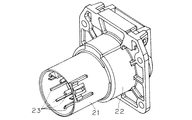
{第3従来技術}
図7に、第3従来技術の牽引車用コネクタを示す。この牽引車用コネクタは、USCAR(米国自動車研究評議会)の標準品であり、車両側コネクタ(図示省略)との接続部21とトレーラー側コネクタ(図示省略)との接続部22の両方が円筒状に形成されている。また、図示していないが、このコネクタ内に挿入されている金属片の回りに間隙が形成されることを考慮し、この間隙をシリコーン系の封止材にて閉塞しており、これにより防水性を確保している。
【0007】
【発明が解決しようとする課題】
第1従来技術では、車両本体側からの電線1をネジ2によりコネクタ本体3内の端子3aに締め付ける構造になっているため、車両の走行振動によってネジ2が緩んでしまうことがあり、ひいては電線1と内部の端子との間に接触不良が発生しやすい。
【0008】
また、電線1を1本ずつネジ2によりコネクタ本体3内の端子3aに締め付けるため、組立時間がかかり、コストが増大する。
【0009】
さらに、防水性について何ら考慮されていないため、端子と電線1との接続部分に水が浸入して金属片等の導体部に腐食が起こるおそれがあり、信頼性や耐久性に問題があった。
【0010】
また、第2従来技術では、トレーラー側のコネクタとの接続部11が円筒状であるのに対して、車両側コネクタとの接続部12が長方形状になっているため、円筒状の接続部11内の配列と長方形状の接続部12内の配列の両方に対応するよう、端子となる金属片を各々異なる形状に形成して別々に用意し、これらを内部で接続する構造をとる必要があった。そのため、金属片の種類が多くなって製造コストが増大する。
【0011】
さらに、防水性についても何ら考慮されていないため、信頼性や耐久性に問題があった。
【0012】
第3従来技術では、第2従来技術と異なり、トレーラー側コネクタ(図示省略)との接続部22だけでなく車両側コネクタとの接続部21をも円筒状としているため、これらの両接続部21,22内に挿入される端子を同位置の配列に設定することができる。このため、両接続部21,22に向けて貫通する同一の金属片23を使用し、第2従来技術に比べて金属片23の個数を低減することが可能であった。
【0013】
しかし、かかる第3従来技術では、車両側コネクタとしては、一般的に使用される長方形状の汎用品を流用することができず、円筒状の専用コネクタを新たに用意する必要があり、コストが増大する。
【0014】
また第3従来技術では、このコネクタの内部に挿入される金属片23の回りの間隙を埋めて防水性を確保する目的でシリコーン系の封止材を充填しているが、コネクタの奥まった位置に封止材を注入する必要があるため、注入時に金属片23の表面に封止材が付着しやすく、付着しても目視にて検出することが非常に困難である。よって、安定した品質の確保が難しい。
【0015】
さらに、第3従来技術で使用されているシリコーン系の封止材は、注入後の硬化時間が長いため、加工コストが増大する。
【0016】
そして、第1従来技術〜第3従来技術のいずれにおいても、接続される車両側ワイヤーハーネスの電線が一部露出することになっている。このため、車両走行時に石などを跳ね上げた場合に、電線1が傷付くおそれがある。
【0017】
これらのことから、この発明の第1の課題は、低コストな牽引車用コネクタを提供することにあり、第2の課題は、防水性の向上により導体部の腐食を有効に防止するとともに電線の保護を有意に実現させ、第3の課題は、コネクタの品質を向上することにある。
【0018】
【課題を解決するための手段】
上記課題を解決すべく、請求項1に記載の発明は、被牽引対象側ワイヤーハーネスに接続される後方側の略円筒状の第1の接続本体と、車両本体側ワイヤーハーネスに接続される略円筒状の第2の接続本体とが互いに逆向きに配置されて形成されるハウジングと、前記ハウジング内において、前記第1の接続本体と前記第2の接続本体との連結部分から前記第1の接続本体に向けて配置され、前記被牽引対象側ワイヤーハーネスのコネクタに接続される第1の端子と、前記ハウジング内において、前記第1の接続本体と前記第2の接続本体との連結部分から前記第2の接続本体に向けて配置され、前記車両本体側ワイヤーハーネスに接続される第2の端子と、前記第1の接続本体と前記第2の接続本体との連結部分の内周に嵌入され、前記第1の端子及び前記第2の端子を保持する端子ホルダーと、前記ハウジング内において、前記第1の接続本体と前記第2の接続本体との連結部分へ挿入され、前記第2の端子を遊挿するための複数の遊挿孔が形成されたリテーナと、を備え、前記第1の端子が、所定の金属片の一端部で構成され、前記第2の端子が、前記金属片の他端で構成され、前記リテーナの前記遊挿孔内において、前記第2の接続本体に接続された前記車両本体側ワイヤーハーネスの芯線と前記第2の端子とが接続されるものである。
【0019】
請求項2に記載の発明は、請求項1に記載の牽引車用コネクタであって、前記ハウジングの内周と前記端子ホルダーの外周との間に嵌入されて前記ハウジング内の水密性を確保する第1の防水手段をさらに備えるものである。
【0020】
請求項3に記載の発明は、請求項1または請求項2に記載の牽引車用コネクタであって、前記端子ホルダーと前記金属片との間の間隙部分に塗布される防水用の熱硬化性の封止材をさらに備えるものである。
【0021】
請求項4に記載の発明は、請求項1に記載の牽引車用コネクタであって、前記第2の端子が、端部が皮剥ぎされた前記車両本体側ワイヤーハーネスの芯線に接続されるものである。
【0022】
請求項5に記載の発明は、請求項4に記載の牽引車用コネクタであって、前記車両本体側ワイヤーハーネスの端部に、前記第2の端子と前記芯線との接続部分への水入りを防止するための防水部材が取り付けられたものである。
【0023】
請求項6に記載の発明は、請求項1ないし請求項4のいずれかに記載の牽引車用コネクタであって、前記第2の接続本体内に前記車両本体側ワイヤーハーネスの端部が挿入された状態で、前記第2の接続本体と、前記車両本体側ワイヤーハーネスの前記第2の接続本体への挿入部分とを覆うプロテクタをさらに備えるものである。
【0024】
請求項7に記載の発明は、請求項6に記載の牽引車用コネクタであって、前記車両本体側ワイヤーハーネスの外周に蛇腹状のコルゲートチューブが装着され、前記プロテクタの内周の一部が、前記コルゲートチューブの形状に対応して形成されたものである。
【0026】
【発明の実施の形態】
図1はこの発明の一の実施の形態に係る牽引車用コネクタを示す分解斜視図、図2は同じくその断面図、図3は同じくその正面図である。
【0027】
この牽引車用コネクタは、トレーラー等の被牽引対象と車両本体との間を電気的に接続するいわゆるトーイングヒッチ用の自動車用ワイヤーハーネスに使用されるものであって、図1の如く、ハウジング30と、このハウジング30内で被牽引対象側ワイヤーハーネスのコネクタ(図示せず)及び車両本体側ワイヤーハーネス35に接続される金属片31としての端子32,33と、ハウジング30内で端子32,33を保持固定するための端子ホルダー34と、ハウジング30内で車両本体側ワイヤーハーネス35の形状を保持するリテーナ36と、車両本体側ワイヤーハーネス35と端子33との接続部分をハウジング30の外側から保護するためのプロテクタ37と、ハウジング30の内周と端子ホルダー34の外周との間に嵌合されてハウジング30内の水密性を保持するためのOリング(第1の防水手段)38とを備える。
【0028】
ハウジング30は、一般的な工業用プラスチックが使用されて金型成形されてなるもので、被牽引対象側ワイヤーハーネスに接続される後方側の略円筒状の第1の接続本体41と、この第1の接続本体41とは逆向きの前方側に配置されて車両本体側ワイヤーハーネス35に接続される略円筒状の第2の接続本体42と、ハウジング30を車両本体に固定するための支持用ブラケット43とが一体形成されてなる。
【0029】
第1の接続本体41は、雄型の被牽引対象側ワイヤーハーネスが嵌入されるよう略円筒状の雌型形状に形成され、外周部に後述の支持用ブラケット43が形成されており、また後端に開口部41aが形成される。当該開口部41aの上端には、被牽引対象側ワイヤーハーネスのコネクタ(図示せず)が接続されていない状態で開口部を閉塞するための蓋体44がヒンジ部45を介して回動自在に取り付けられている。尚、ヒンジ部45は、蓋体44の端部から外向けに突出された回動軸45aが第1の接続本体41の上端端部に形成された軸受け45bに軸支されており、回動軸45aの外周に巻き付けられた巻きバネ45cにより、蓋体44が第1の接続本体41の開口部41aを閉塞する方向に当該蓋体44を付勢している。
【0030】
第2の接続本体42は、車両本体側ワイヤーハーネス35が直接挿入されるよう略円筒状の雌型形状に形成され、後端が第1の接続本体41に一体的に連結される。第2の接続本体42の前端部42aの内周には、図3の如く、内部フレーム46が形成されており、この内部フレーム46には、端部が皮剥ぎされた車両本体側ワイヤーハーネス35の芯線端部を挿入及び位置決めするための複数の位置決め孔46aが形成されている。
【0031】
支持用ブラケット43は、正面視台形状の支持板であり、当該支持用ブラケット43の下端の両端部には円形の圧入孔47が形成され、当該圧入孔47に、車両本体側の圧入用突起(図示省略)を圧入されたときに当該支持用ブラケット43を補強するための円環状の圧入カラー48が填め込まれている。
【0032】
各端子32,33は、図2の如く、それぞれ一枚の金属片31を折曲して形成されており、後述の端子ホルダー34に圧入される。金属片31の一端部の第1の接続本体41側に向かう第1の端子32は略楔状に折曲されて、筒形状の半径方向に弾性を有するバネ部材51とされている。また、各金属片31の他端部の第2の端子33は、第1の接続本体41側の開口部41aから挿入されて、第2の接続本体42の内部フレーム46の位置決め孔46aに向くように遊貫される。これにより、同一の金属片31で、被牽引対象側ワイヤーハーネスに接続する第1の端子32と、車両本体側ワイヤーハーネス35に接続する第2の端子33の両方を兼ねることが可能となる。
【0033】
端子ホルダー34は、円筒状の第1の接続本体41の内周の形状に合致した正面視円形状に形成され、6個の金属片31が圧入される圧入孔53が形成されており、この圧入孔53の配置は、金属片31が第2の接続本体42内の内部フレーム46の位置決め孔46aに対応して配列されるように設定されている。
【0034】
リテーナ36は、円筒状の第1の接続本体41と第2の接続本体42の間の連結部分の内周の形状に合致した正面視円形状に形成され、端子ホルダー34に支持された第2の端子33を遊挿するための複数の遊挿孔36aが形成されており、第1の接続本体41側から第2の接続本体42との連結部分へ挿入される。このリテーナ36の各遊挿孔36aは、第2の接続本体42の内部フレーム46の位置決め孔46aに対応するよう配置され、前端側から位置決め孔46aに挿入される車両本体側ワイヤーハーネス35の芯線と第2の端子33とが、各遊挿孔36a内で接続される。
【0035】
プロテクタ37は、第2の接続本体42に車両本体側ワイヤーハーネス35の端部が挿入された状態でこれらを外部から保護するためのもので、第2の接続本体42の外周部を覆う接続部保護体37aと、車両本体側ワイヤーハーネス35の外周の保護用の蛇腹状のコルゲートチューブ52の一部を覆うチューブ保護体37bとが一体的に形成された筒体が、正面視半円形状に2つに分割された一対の半円筒状体53a,53bが、ヒンジ部54で開閉自在に構成されている。特に、外部からの水入りを防止する目的で、チューブ保護体37bの内周は、蛇腹状のコルゲートチューブ52に対応した形状とされている。
【0036】
Oリング38は、第1の接続本体41内に填め込まれて、内部に端子ホルダー34の前端部を圧入することで、端子ホルダー34を第1の接続本体41内に固定するとともに、その水密性を高めるためのものである。尚、ハウジング30の第1の接続本体41と第2の接続本体42との連結部分の内周には、Oリング38が当接するための段部56が形成されている。
【0037】
そして、端子ホルダー34に金属片31が圧入された圧入孔53に発生した間隙部分の表面には、熱硬化性の封止材57が充填され、その部分での水密性が確保されている。尚、この封止材57は、金属片31が圧入された端子ホルダー34が第1の接続本体41内に填め込まれる以前に、圧入孔53の表面に露出している部分に予め塗布される。これにより、封止材57が金属片31の表面に付着しても、目視による検出が容易になる。
【0038】
尚、車両本体側ワイヤーハーネス35としては、図2の如く、その端部に、当該車両本体側ワイヤーハーネス35が第2の接続本体42の内部フレーム46の位置決め孔46aに挿入されたときに、この位置決め孔46aを閉塞するためのセパレート型のゴム栓(防水部材)59が予め取り付けられたものが使用される。
【0039】
上記構成の牽引車用コネクタの組立方法を説明する。
【0040】
まず、各金属片31を端子ホルダー34の圧入孔53に挿入し、端子ホルダー34の圧入孔53の表面に露出している部分に、熱硬化性の封止材57を塗布・充填した後、これを過熱して封止材57を硬化させる。このように、水密性を高めるための封止材57を、ハウジング30内に挿入する前の端子ホルダー34の圧入孔53に塗布・充填するので、封止材57が金属片31の表面に付着しても、目視による検出が容易になる。
【0041】
次に、第1の接続本体41側で蓋体44を開き、この第1の接続本体41の開口部41aからリテーナ36を挿入して、奥(前側)の第2の接続本体42まで押し込む。このとき、リテーナ36の遊挿孔36aが第2の接続本体42の内部フレーム46の位置決め孔46aに対応するよう配置する。
【0042】
次に、Oリング38を第1の接続本体41の開口部41aから挿入し、このOリング38を、第1の接続本体41と第2の接続本体42との連結部分の内周に形成された段部56に当接するまで押し込む。
【0043】
続いて、金属片31が圧入されるとともに封止材57が形成された端子ホルダー34を、第1の接続本体41の内部に嵌入する。この際、端子ホルダー34に支持された各金属片31の第2の端子33が、リテーナ36の遊挿孔36a内に遊貫するように位置決めしながら、端子ホルダー34を嵌入する。
【0044】
そうすると、端子ホルダー34の外周とハウジング30との内周との間がOリング38により水密状に保たれるとともに、端子ホルダー34の圧入孔53が封止材57とにより水密状に保たれ、これらによりハウジング30内部の防水状態が保持されることになる。
【0045】
続いて、第2の端子33の前端部において、車両本体側ワイヤーハーネス35を、第2の接続本体42の内部フレーム46の位置決め孔46aから内部へ挿入する。そうすると、リテーナ36の遊挿孔36a内において、車両本体側ワイヤーハーネス35の芯線と第2の端子33とが接続する。
【0046】
ここで、車両本体側ワイヤーハーネス35は、その端部にセパレート型のゴム栓59が予め取り付けられたものが使用されているので、この第2の端子33の前端部において、ゴム栓59が第2の接続本体42の内部フレーム46の位置決め孔46aを閉塞し、この部分における防水性が確保される。
【0047】
そして、プロテクタ37の一対の半円筒状体53a,53bをヒンジ部54で開放した状態で、第2の接続本体42及び車両本体側ワイヤーハーネス35の端部に近づけ、ヒンジ部54を回動して両半円筒状体53a,53bを閉じた状態にし、プロテクタ37で第2の接続本体42及び車両本体側ワイヤーハーネス35の端部を覆い込む。この際、プロテクタ37の接続部保護体37aが第2の接続本体42を覆い、同じくチューブ保護体37bが車両本体側ワイヤーハーネス35のコルゲートチューブ52を覆った状態となる。特に、コルゲートチューブ52が蛇腹状になっており、チューブ保護体37bの内周は、蛇腹状のコルゲートチューブ52に対応した形状とされているので、外部からの水入りを容易に防止することができる。
【0048】
かかる状態で、ハウジング30の支持用ブラケット43の圧入カラー48に車両本体の所定の圧入杆を圧入し、牽引車用コネクタを車両本体に固定する。
【0049】
そして、車両本体にトレーラー等の被牽引対象が取り付けられる際に、ハウジング30の蓋体44を開け、雄型の被牽引対象側ワイヤーハーネスのコネクタ(図示せず)を第1の接続本体41の開口部41aに挿入して接続すればよい。
【0050】
以上のように、被牽引対象側ワイヤーハーネスのコネクタと接続する後方側の第1の接続本体41と、車両本体側ワイヤーハーネス35と接続する前方側の第2の接続本体42の両方が略円筒形状とされているので、内部の端子32,33の配置を同様に設定することができ、両端子32,33とも同一の金属片31を用いて形成することができる。したがって、例えば第2従来技術に比べて、部品点数が少なくて済み、部品コストを低減できる。
【0051】
また、第2の接続本体42は、車両本体側ワイヤーハーネス35の各電線の端部を直接接続する構造となっているため、この第2の接続本体42に接続するための専用のコネクタを使用する必要がない。したがって、円筒状の専用コネクタを新たに用意する必要があった第3従来技術に比べて、部品コストを低減できる。
【0052】
さらに、端子ホルダー34の圧入孔53に発生する間隙部分の表面を封止する封止材57として熱硬化性のものを使用しているので、硬化時間を短縮することができ、第3従来技術に比べて製造効率を高めて製造コストを低減できる。
【0053】
これらのことから、全体として製造コストを低減できる牽引車用コネクタを提供できる。
【0054】
また、端子32,33となる金属片31を挿入する際、予め端子ホルダー34に金属片31を圧入し、圧入孔53に発生する間隙部分に封止材57を塗布・充填してからハウジング30内に挿入するようにしているので、この封止材57の注入作業性が向上し、また、万一封止材57が金属片31の表面に付着して導通不良の原因となるような場合であっても、その旨の目視による検出が容易となる。したがって、牽引車用コネクタの製造品質を容易に向上できる。
【0055】
さらに、車両本体側ワイヤーハーネス35として、端部にセパレート型のゴム栓59が予め取り付けられたものが使用されているので、ハウジング30の第2の端子33の前端部において、ゴム栓59が第2の接続本体42の内部フレーム46の位置決め孔46aを容易に閉塞でき、この部分における防水性が確保される。
【0056】
また、封止材57及びOリング38により、ハウジング30内部への後方または前方からの水入りを容易に防止できる。
【0057】
さらに、プロテクタ37が、第2の接続本体42から車両本体側ワイヤーハーネス35のコルゲートチューブ52にかけて覆い被さるように取り付けられるので、車両本体側ワイヤーハーネス35の牽引車用コネクタへの取り付け部分を確実に保護できる。特に、プロテクタ37のチューブ保護体37bの内周がコルゲートチューブ52の外周形状に対応した形状とされているので、この部分での外部環境からの保護が確実となる。
【0058】
これらのことから、第1従来技術ないし第3従来技術に比べて、防水性を高め得るとともに、車両本体側ワイヤーハーネス35の端部を外部環境から確実に保護することが可能となる。
【0059】
【発明の効果】
請求項1に記載の発明によれば、ハウジングの被牽引対象側ワイヤーハーネスに接続される後方側の第1の接続本体と、これに逆向きに配置されて車両本体側ワイヤーハーネスに接続される第2の接続本体とが共に略円筒形状に形成されているので、内部の端子の配置を第1の接続本体と第2の接続本体とで同様に設定することができる。したがって、両端子とも同一の金属片を用いて形成することができ、例えば第2従来技術に比べて、部品点数が少なくて済み、部品コストを低減できる。またハウジング内において複数の遊挿孔が形成されたリテーナを備えるので、リテーナの遊挿孔内において、第2の接続本体に接続された車両本体側ワイヤーハーネスの芯線と端子ホルダにより保持された第2の端子とを接続できる。
【0060】
請求項2に記載の発明によれば、ハウジングの内周と端子ホルダーの外周との間に第1の防水手段が嵌入され、また、請求項3に記載の発明によれば、端子ホルダーと金属片との間の間隙部分に熱硬化性の封止材が塗布されるので、ハウジング内の水密性を確保することができる。
【0061】
特に、請求項3に記載の発明によれば、封止材として熱硬化性のものを使用しているので、硬化時間を短縮することができ、また、ハウジング内に直接封止材を充填する場合に比べて、このハウジングとは別体の端子ホルダーに封止材を塗布できることから、例えば第3従来技術に比べて製造効率を高めて製造コストを低減できる。そして、万一封止材が金属片の表面に付着して導通不良の原因となるような場合であっても、その旨の目視による検出が容易となる。したがって、牽引車用コネクタの製造品質を容易に向上できる。
【0062】
請求項4に記載の発明によれば、第2の端子が、端部が皮剥ぎされた車両本体側ワイヤーハーネスの芯線に接続されるので、この第2の接続本体に接続するための専用のコネクタを使用する必要がない。したがって、円筒状の専用コネクタを新たに用意する必要があった第3従来技術に比べて、部品コストを低減できる。
【0063】
請求項5に記載の発明によれば、車両本体側ワイヤーハーネスの端部に防水部材が取り付けられているので、その芯線と第2の端子と接続部分への水入りを容易に防止することができる。
【0064】
請求項6に記載の発明によれば、第2の接続本体内に車両本体側ワイヤーハーネスの端部が挿入された状態で、第2の接続本体と、車両本体側ワイヤーハーネスの第2の接続本体への挿入部分とを覆うプロテクタをさらに備えるので、車両本体側ワイヤーハーネスの牽引車用コネクタへの取り付け部分を確実に保護できる。
【0065】
請求項7に記載の発明によれば、車両本体側ワイヤーハーネスの外周に蛇腹状のコルゲートチューブが装着され、プロテクタの内周の一部が、コルゲートチューブの形状に対応して形成されているので、この部分での水入り等の外部環境からの保護が確実となる。
【図面の簡単な説明】
【図1】この発明の一の実施の形態に係る牽引車用コネクタを示す分解斜視図である。
【図2】この発明の一の実施の形態に係る牽引車用コネクタを示す断面図である。
【図3】この発明の一の実施の形態に係る牽引車用コネクタを示す正面図である。
【図4】第1従来技術の牽引車用コネクタを示す斜視図である。
【図5】第1従来技術の牽引車用コネクタにおいて電線と端子がねじ止めされる様子を示す斜視図である。
【図6】第2従来技術の牽引車用コネクタを示す斜視図である。
【図7】第3従来技術の牽引車用コネクタを示す斜視図である。
【符号の説明】
30 ハウジング
31 金属片
32 第1の端子
33 第2の端子
34 端子ホルダー
35 車両本体側ワイヤーハーネス
36 リテーナ
36a 遊挿孔
37 プロテクタ
37a 接続部保護体
37b チューブ保護体
38 Oリング
41 接続本体
41a 開口部
42 接続本体
43 支持用ブラケット
44 蓋体
45 ヒンジ部
51 バネ部材
52 コルゲートチューブ
53 圧入孔
56 段部
57 封止材
59 ゴム栓[0001]
BACKGROUND OF THE INVENTION
The present invention relates to a tow vehicle connector and a technology related thereto.
[0002]
[Prior art]
In a tow vehicle, a vehicle body side connector used for an automotive wire harness for a so-called towing hitch that electrically connects a towed object such as a trailer and the vehicle body is prepared by a general user in the market. The shape and dimensions are standardized by SAE (American Automotive Engineers Association) standard or JIS (Japanese Standards Association) standard, etc. so that it can be electrically connected to the trailer side wire harness, ensuring compatibility between various vehicle types. is doing. For example, in the United States, “7-Way Connector” marketed by several manufacturers is a de facto industry standard.
[0003]
This "7-Way Connector" has connection compatibility with the trailer side connector (cylindrical), and there are three types as follows.
[0004]
{First prior art}
The tow vehicle connector of the first prior art shown in FIGS. 4 and 5 is fastened by fixing the electric wire 1 from the vehicle main body side to the
[0005]
{Second prior art}
FIG. 6 shows a tow vehicle connector according to the technique (second prior art) of US Pat. No. 5,800,188. In the second prior art, a
[0006]
{Third prior art}
FIG. 7 shows a tow vehicle connector according to the third prior art. This tow vehicle connector is a standard product of USCAR (United States Automotive Research Council), and both the connecting
[0007]
[Problems to be solved by the invention]
In the first prior art, since the electric wire 1 from the vehicle main body side is tightened to the
[0008]
Further, since the electric wires 1 are fastened to the
[0009]
Furthermore, since no consideration is given to waterproofness, there is a possibility that water may enter the connecting portion between the terminal and the electric wire 1 and corrosion may occur in a conductor portion such as a metal piece, which has a problem in reliability and durability. .
[0010]
In the second prior art, the connecting
[0011]
Furthermore, since no consideration was given to waterproofness, there was a problem in reliability and durability.
[0012]
In the third prior art, unlike the second prior art, not only the connecting
[0013]
However, in the third prior art, a generally used rectangular general-purpose product cannot be used as the vehicle-side connector, and it is necessary to newly prepare a cylindrical dedicated connector, which is costly. Increase.
[0014]
In the third prior art, a silicone-based sealing material is filled for the purpose of filling the gap around the
[0015]
Furthermore, the silicone-based sealing material used in the third prior art has a long curing time after injection, which increases the processing cost.
[0016]
And in any of a 1st prior art-a 3rd prior art, the electric wire of the vehicle side wire harness connected is to be exposed partially. For this reason, there is a possibility that the electric wire 1 may be damaged when a stone or the like is flipped up while the vehicle is traveling.
[0017]
Accordingly, a first object of the present invention is to provide a low-cost tow vehicle connector, and a second problem is to effectively prevent corrosion of a conductor part by improving waterproofness and to provide an electric wire. The third problem is to improve the quality of the connector.
[0018]
[Means for Solving the Problems]
In order to solve the above-mentioned problems, the invention according to claim 1 is a substantially cylindrical first connection main body on the rear side connected to the to-be-towed object side wire harness and a general connection connected to the vehicle main body side wire harness. A housing formed by arranging a cylindrical second connection main body in opposite directions, and the first connection main body and the second connection main body within the housing from a connecting portion of the first connection main body and the second connection main body. A first terminal that is arranged toward the connection body and connected to the connector of the to-be-drawn object-side wire harness, and a connection portion between the first connection body and the second connection body in the housing. A second terminal that is disposed toward the second connection body and is connected to the vehicle body-side wire harness, and is fitted into an inner periphery of a connecting portion between the first connection body and the second connection body. And said A terminal holder for holding the terminal and the second terminal, within the housing, is inserted into the connecting portion between said first connecting body and the second connecting body, loosely inserted the second terminal And a retainer in which a plurality of loose insertion holes are formed , wherein the first terminal is constituted by one end portion of a predetermined metal piece, and the second terminal is constituted by the other end of the metal piece. is, in the loose insertion hole of the retainer, the core wire of the second connecting said vehicle body side wire harness connected to the body and said second terminal is shall be connected.
[0019]
The invention according to
[0020]
Invention of Claim 3 is the connector for tow vehicles of Claim 1 or
[0021]
Invention of Claim 4 is a connector for tow vehicles of Claim 1, Comprising: A said 2nd terminal is connected to the core wire of the said vehicle main body side wire harness by which the edge part was peeled off It is.
[0022]
Invention of Claim 5 is a connector for tow vehicles of Claim 4, Comprising: Water enters into the connection part of a said 2nd terminal and the said core wire in the edge part of the said vehicle main body side wire harness. A waterproofing member for preventing this is attached.
[0023]
A sixth aspect of the present invention is the tow vehicle connector according to any one of the first to fourth aspects, wherein an end of the vehicle body side wire harness is inserted into the second connection body. And a protector that covers the second connection body and a portion of the vehicle body-side wire harness that is inserted into the second connection body.
[0024]
The invention according to claim 7 is the tow vehicle connector according to claim 6, wherein a bellows-like corrugated tube is attached to the outer periphery of the vehicle body side wire harness, and a part of the inner periphery of the protector is These are formed corresponding to the shape of the corrugated tube.
[0026]
DETAILED DESCRIPTION OF THE INVENTION
FIG. 1 is an exploded perspective view showing a tow vehicle connector according to an embodiment of the present invention, FIG. 2 is a sectional view thereof, and FIG. 3 is a front view thereof.
[0027]
This tow vehicle connector is used for an automotive wire harness for a so-called towing hitch that electrically connects a to-be-towed object such as a trailer and the vehicle body. As shown in FIG. And the
[0028]
The
[0029]
The
[0030]
The second connection
[0031]
The
[0032]
As shown in FIG. 2, each of the
[0033]
The
[0034]
The
[0035]
The
[0036]
The O-
[0037]
Then, the surface of the gap portion generated in the press-fitting
[0038]
As shown in FIG. 2, when the vehicle body
[0039]
A method for assembling the tow vehicle connector configured as described above will be described.
[0040]
First, each
[0041]
Next, the
[0042]
Next, the O-
[0043]
Subsequently, the
[0044]
Then, the outer periphery of the
[0045]
Subsequently, at the front end of the
[0046]
Here, since the vehicle body
[0047]
Then, with the pair of
[0048]
In this state, a predetermined press-fitting rod of the vehicle body is press-fitted into the press-fitting
[0049]
Then, when a towed object such as a trailer is attached to the vehicle body, the
[0050]
As described above, both the first connection
[0051]
Moreover, since the 2nd connection
[0052]
Further, since a thermosetting material is used as the sealing
[0053]
From these things, the connector for tow vehicles which can reduce manufacturing cost as a whole can be provided.
[0054]
Further, when the
[0055]
Further, since the vehicle body
[0056]
Further, the sealing
[0057]
Furthermore, since the
[0058]
From these facts, it is possible to improve the waterproofness as compared with the first prior art to the third prior art, and to reliably protect the end portion of the vehicle body
[0059]
【The invention's effect】
According to the first aspect of the present invention, the first connection main body on the rear side connected to the to-be-traction target side wire harness of the housing, and the first connection main body arranged in the opposite direction to the first connection main body are connected to the vehicle main body side wire harness. Since both the second connection main bodies are formed in a substantially cylindrical shape, the arrangement of the internal terminals can be set similarly between the first connection main body and the second connection main body. Therefore, both terminals can be formed using the same metal piece. For example, compared with the second prior art, the number of parts can be reduced, and the part cost can be reduced. Moreover, since the retainer in which a plurality of loose insertion holes are formed in the housing is provided, in the loose insertion hole of the retainer , the first wire harness held by the core wire and the terminal holder of the vehicle body side wire harness connected to the
[0060]
According to the second aspect of the present invention, the first waterproof means is inserted between the inner periphery of the housing and the outer periphery of the terminal holder. Further, according to the third aspect of the present invention, the terminal holder and the metal Since the thermosetting sealing material is applied to the gap portion between the pieces, the water tightness in the housing can be ensured.
[0061]
In particular, according to the invention described in claim 3, since a thermosetting material is used as the sealing material, the curing time can be shortened, and the sealing material is directly filled in the housing. Compared to the case, since the sealing material can be applied to a terminal holder separate from the housing, for example, the manufacturing efficiency can be increased and the manufacturing cost can be reduced as compared with the third prior art. And even if a sealing material adheres to the surface of a metal piece and causes a conduction failure, the visual detection to that effect becomes easy. Therefore, the manufacturing quality of the tow vehicle connector can be easily improved.
[0062]
According to the invention described in claim 4, since the second terminal is connected to the core wire of the vehicle body-side wire harness whose end portion is peeled off, a dedicated terminal for connecting to the second connection body is provided. There is no need to use a connector. Therefore, compared with the 3rd prior art which needed to prepare a cylindrical exclusive connector newly, parts cost can be reduced.
[0063]
According to invention of Claim 5, since the waterproof member is attached to the edge part of the vehicle main body side wire harness, it can prevent easily that the core wire, the 2nd terminal, and the water-entry to a connection part enter. it can.
[0064]
According to the invention of claim 6, the second connection body and the second connection of the vehicle body side wire harness in a state where the end of the vehicle body side wire harness is inserted into the second connection body. Since the protector which covers the insertion part to a main body is further provided, the attachment part to the connector for towing vehicles of the vehicle main body side wire harness can be protected reliably.
[0065]
According to the seventh aspect of the present invention, the bellows-like corrugated tube is attached to the outer periphery of the vehicle body side wire harness, and a part of the inner periphery of the protector is formed corresponding to the shape of the corrugated tube. In this part, protection from the outside environment such as entering water is ensured.
[Brief description of the drawings]
FIG. 1 is an exploded perspective view showing a tow vehicle connector according to an embodiment of the present invention.
FIG. 2 is a cross-sectional view showing a tow vehicle connector according to one embodiment of the present invention.
FIG. 3 is a front view showing a tow vehicle connector according to one embodiment of the present invention.
FIG. 4 is a perspective view showing a tow vehicle connector according to the first prior art.
FIG. 5 is a perspective view showing a state in which the electric wire and the terminal are screwed in the tow vehicle connector of the first prior art.
FIG. 6 is a perspective view showing a tow vehicle connector according to a second prior art.
FIG. 7 is a perspective view showing a tow vehicle connector according to a third prior art.
[Explanation of symbols]
30
Claims (7)
前記ハウジング内において、前記第1の接続本体と前記第2の接続本体との連結部分から前記第1の接続本体に向けて配置され、前記被牽引対象側ワイヤーハーネスのコネクタに接続される第1の端子と、
前記ハウジング内において、前記第1の接続本体と前記第2の接続本体との連結部分から前記第2の接続本体に向けて配置され、前記車両本体側ワイヤーハーネスに接続される第2の端子と、
前記第1の接続本体と前記第2の接続本体との連結部分の内周に嵌入され、前記第1の端子及び前記第2の端子を保持する端子ホルダーと、
前記ハウジング内において、前記第1の接続本体と前記第2の接続本体との連結部分へ挿入され、前記第2の端子を遊挿するための複数の遊挿孔が形成されたリテーナと、
を備え、
前記第1の端子が、所定の金属片の一端部で構成され、
前記第2の端子が、前記金属片の他端で構成され、
前記リテーナの前記遊挿孔内において、前記第2の接続本体に接続された前記車両本体側ワイヤーハーネスの芯線と前記端子ホルダに保持された前記第2の端子とが接続されることを特徴とする牽引車用コネクタ。A substantially cylindrical first connection body on the rear side connected to the to-be-targeted wire harness and a substantially cylindrical second connection body connected to the vehicle body-side wire harness are arranged in opposite directions. A housing formed by
In the housing, the first connection body is arranged from the connecting portion of the first connection body and the second connection body toward the first connection body, and is connected to the connector of the to-be-to-target wire harness. The terminal of
In the housing, a second terminal that is arranged from the connecting portion of the first connection body and the second connection body toward the second connection body and is connected to the vehicle body-side wire harness; ,
A terminal holder that is fitted into an inner periphery of a coupling portion between the first connection body and the second connection body, and holds the first terminal and the second terminal ;
In the housing, a retainer that is inserted into a coupling portion between the first connection body and the second connection body, and has a plurality of loose insertion holes for loosely inserting the second terminals;
With
The first terminal is constituted by one end of a predetermined metal piece,
The second terminal is constituted by the other end of the metal piece ;
The core wire of the vehicle body side wire harness connected to the second connection body and the second terminal held by the terminal holder are connected in the loose insertion hole of the retainer. Towing vehicle connector.
前記ハウジングの内周と前記端子ホルダーの外周との間に嵌入されて前記ハウジング内の水密性を確保する第1の防水手段をさらに備える牽引車用コネクタ。The tow vehicle connector according to claim 1,
A tow vehicle connector further comprising first waterproof means that is fitted between an inner periphery of the housing and an outer periphery of the terminal holder to ensure water tightness in the housing.
前記端子ホルダーと前記金属片との間の間隙部分に塗布される防水用の熱硬化性の封止材をさらに備える牽引車用コネクタ。The tow vehicle connector according to claim 1 or 2,
A tow vehicle connector further comprising a waterproof thermosetting sealing material applied to a gap portion between the terminal holder and the metal piece.
前記第2の端子が、端部が皮剥ぎされた前記車両本体側ワイヤーハーネスの芯線に接続されることを特徴とする牽引車用コネクタ。The tow vehicle connector according to claim 1,
The tow vehicle connector, wherein the second terminal is connected to a core wire of the vehicle body side wire harness whose end is peeled off.
前記車両本体側ワイヤーハーネスの端部に、前記第2の端子と前記芯線との接続部分への水入りを防止するための防水部材が取り付けられたことを特徴とする牽引車用コネクタ。The tow vehicle connector according to claim 4,
A tow vehicle connector, wherein a waterproof member for preventing water from entering a connecting portion between the second terminal and the core wire is attached to an end portion of the vehicle body side wire harness.
前記第2の接続本体内に前記車両本体側ワイヤーハーネスの端部が挿入された状態で、前記第2の接続本体と、前記車両本体側ワイヤーハーネスの前記第2の接続本体への挿入部分とを覆うプロテクタをさらに備える牽引車用コネクタ。A tow vehicle connector according to any one of claims 1 to 4,
With the end of the vehicle main body side wire harness inserted into the second connection main body, the second connection main body, and the insertion portion of the vehicle main body side wire harness into the second connection main body, A tow vehicle connector further comprising a protector for covering.
前記車両本体側ワイヤーハーネスの外周に蛇腹状のコルゲートチューブが装着され、
前記プロテクタの内周の一部が、前記コルゲートチューブの形状に対応して形成されたことを特徴とする牽引車用コネクタ。The tow vehicle connector according to claim 6,
A bellows-like corrugated tube is attached to the outer periphery of the vehicle body side wire harness,
A tow vehicle connector, wherein a part of the inner periphery of the protector is formed corresponding to the shape of the corrugated tube.
Priority Applications (2)
| Application Number | Priority Date | Filing Date | Title |
|---|---|---|---|
| JP2002191960A JP4005426B2 (en) | 2002-07-01 | 2002-07-01 | Tow truck connector |
| US10/611,242 US6814581B2 (en) | 2002-01-07 | 2003-06-30 | Connector for towing vehicle and method of manufacturing same |
Applications Claiming Priority (1)
| Application Number | Priority Date | Filing Date | Title |
|---|---|---|---|
| JP2002191960A JP4005426B2 (en) | 2002-07-01 | 2002-07-01 | Tow truck connector |
Publications (2)
| Publication Number | Publication Date |
|---|---|
| JP2004039332A JP2004039332A (en) | 2004-02-05 |
| JP4005426B2 true JP4005426B2 (en) | 2007-11-07 |
Family
ID=31701385
Family Applications (1)
| Application Number | Title | Priority Date | Filing Date |
|---|---|---|---|
| JP2002191960A Expired - Lifetime JP4005426B2 (en) | 2002-01-07 | 2002-07-01 | Tow truck connector |
Country Status (2)
| Country | Link |
|---|---|
| US (1) | US6814581B2 (en) |
| JP (1) | JP4005426B2 (en) |
Families Citing this family (37)
| Publication number | Priority date | Publication date | Assignee | Title |
|---|---|---|---|---|
| JP2004288545A (en) * | 2003-03-24 | 2004-10-14 | Yazaki Corp | Connector protector |
| JP4210923B2 (en) * | 2003-11-21 | 2009-01-21 | 住友電装株式会社 | Vehicle outlet cover |
| DE102004024484A1 (en) * | 2004-05-14 | 2005-12-08 | Murrplastik Systemtechnik Gmbh | Electrical wiring system, has plastic fixing socket with two half shells partially encompassing terminal coupling and protecting hose, where coupling is fixed at hose in its longitudinal direction by socket |
| US7118379B1 (en) * | 2004-11-05 | 2006-10-10 | Jen-Ching Wang | Female connector member for towing connector |
| US7291017B1 (en) * | 2005-04-11 | 2007-11-06 | Beverly Fain | Power interface device for trailer hitches |
| US20090311881A1 (en) * | 2008-06-11 | 2009-12-17 | U-Haul International, Inc. | Split Plug Electrical Connector for Towing |
| JP5447962B2 (en) * | 2010-02-19 | 2014-03-19 | 住友電装株式会社 | Charging connector |
| US8323036B2 (en) | 2010-04-23 | 2012-12-04 | Tow Daddy, Inc. | Wiring harness for towing a vehicle |
| EP2456015A3 (en) * | 2010-11-23 | 2012-07-18 | ERICH JAEGER GmbH + Co. KG | Motor vehicle coupling socket |
| CA2819244C (en) * | 2010-12-03 | 2015-03-31 | Enozo Technologies, Inc. | Electrolytic cell for ozone production |
| JP5643073B2 (en) * | 2010-12-10 | 2014-12-17 | 矢崎総業株式会社 | Wire harness and method of manufacturing wire harness |
| DE102012024588B4 (en) | 2012-12-17 | 2023-11-16 | HARTING Automotive GmbH | Connectors |
| US9325099B2 (en) | 2013-01-22 | 2016-04-26 | Hypertronics Corporation | Coupling system including a receptacle housing with a rotating domed door |
| US9205788B2 (en) | 2013-01-22 | 2015-12-08 | Meyer Products, Llc | Vehicle to snow/ice control device wiring harness with replaceable connector |
| EP2781395A1 (en) * | 2013-03-21 | 2014-09-24 | Delphi International Operations Luxembourg S.à r.l. | Cable connector and connector assembly process |
| US9438051B2 (en) * | 2013-05-03 | 2016-09-06 | Casco Products Corporation | USB power outlet/charger direct replacement for automotive cigar lighter/power outlet |
| US9755447B2 (en) * | 2014-04-04 | 2017-09-05 | Carling Technologies, Inc. | Panel mounted USB charger |
| JP6346802B2 (en) * | 2014-06-20 | 2018-06-20 | 矢崎総業株式会社 | connector |
| CN105449442A (en) * | 2014-09-25 | 2016-03-30 | 西安乐食智能餐具有限公司 | Waterproof wiring device and electronic device |
| DE102014015148B4 (en) * | 2014-10-13 | 2018-11-29 | Sumitomo Wiring Systems, Ltd. | Charging connector and method for mounting the same |
| EP3029936A1 (en) | 2014-12-05 | 2016-06-08 | Axis AB | Method and device for real-time encoding |
| CN104505604B (en) * | 2014-12-31 | 2017-06-06 | 深圳大成创安达电子科技发展有限公司 | A kind of waterproof wiring folder |
| JP6358141B2 (en) * | 2015-03-25 | 2018-07-18 | 住友電装株式会社 | Wire harness protector fixing structure |
| USD857630S1 (en) * | 2016-06-29 | 2019-08-27 | R&S Shaeffer Properties LLC | Plug receptacle assembly |
| US9590342B1 (en) | 2016-06-29 | 2017-03-07 | R&S Shaeffer Properties LLC | Receptacle assemblies |
| US9559475B1 (en) * | 2016-06-29 | 2017-01-31 | R&S Shaeffer Properties LLC | Plug assemblies |
| USD848949S1 (en) * | 2016-06-29 | 2019-05-21 | R&S Shaeffer Properties LLC | Socket receptacle assembly |
| US9966713B1 (en) | 2017-01-18 | 2018-05-08 | R&S Shaeffer Properties LLC | Receptacle assemblies |
| US10027072B1 (en) * | 2017-01-18 | 2018-07-17 | R&S Schaeffer Properties LLC | Plug assemblies |
| JP6708355B2 (en) * | 2017-09-11 | 2020-06-10 | 矢崎総業株式会社 | Connector cover |
| TWM569505U (en) * | 2018-05-15 | 2018-11-01 | 崧騰企業股份有限公司 | Electrical connector set with multi electrical-connection directionality |
| JP2020140817A (en) | 2019-02-27 | 2020-09-03 | 住友電装株式会社 | connector |
| JP6936269B2 (en) * | 2019-03-26 | 2021-09-15 | 矢崎総業株式会社 | Connector fitting manufacturing system |
| DE102020109786A1 (en) * | 2020-04-08 | 2021-10-14 | Mts Sensor Technologie Gmbh & Co. Kg | Connection device |
| JP7268083B2 (en) * | 2021-05-13 | 2023-05-02 | 矢崎総業株式会社 | protector and wire harness |
| MX2024009572A (en) * | 2022-02-04 | 2024-08-13 | Ideal Ind | SEALED CONNECTOR. |
| WO2024210891A1 (en) * | 2023-04-04 | 2024-10-10 | Itt Cannon Gmbh | Frame electric vehicle (ev) connector with overmolding |
Family Cites Families (3)
| Publication number | Priority date | Publication date | Assignee | Title |
|---|---|---|---|---|
| US4545633A (en) * | 1983-07-22 | 1985-10-08 | Whittaker Corporation | Weatherproof positive lock connector |
| GB2272799A (en) * | 1992-10-20 | 1994-05-25 | Ian Hambrook | Cable termination to electrical connectors |
| US5800188A (en) * | 1996-02-09 | 1998-09-01 | Joseph Pollak Corporation | Direct connect trailer tow interconnector |
-
2002
- 2002-07-01 JP JP2002191960A patent/JP4005426B2/en not_active Expired - Lifetime
-
2003
- 2003-06-30 US US10/611,242 patent/US6814581B2/en not_active Expired - Lifetime
Also Published As
| Publication number | Publication date |
|---|---|
| US20040053525A1 (en) | 2004-03-18 |
| US6814581B2 (en) | 2004-11-09 |
| JP2004039332A (en) | 2004-02-05 |
Similar Documents
| Publication | Publication Date | Title |
|---|---|---|
| JP4005426B2 (en) | Tow truck connector | |
| JP2580724Y2 (en) | Shield connector for device direct mounting | |
| JP5622307B2 (en) | Shield connector | |
| US9385516B2 (en) | Connector | |
| US9231337B2 (en) | Connector and mounting method therefor | |
| US11296453B2 (en) | Waterproof structure of connector | |
| WO2011007607A1 (en) | Waterproof structure | |
| JP2019040788A (en) | Shield connector directly attached to apparatus | |
| JP5170013B2 (en) | Shield connector | |
| JP4638064B2 (en) | Waterproof connection structure and method for electronic unit and electric wire | |
| JP7790604B2 (en) | Wire-attached connector | |
| JP3627974B2 (en) | Waterproof structure and assembly method for panel feed-through connector | |
| JP2014038785A (en) | Waterproof plug and cord with waterproof plug | |
| JPH0644040U (en) | Insulator for terminal connection | |
| JP2570350Y2 (en) | Shield connector | |
| US12278446B2 (en) | Self-sealing electrical plug-and-socket assembly | |
| JP2002134953A (en) | Connection structure and connection method between electronic unit and shielded cable | |
| JP4278556B2 (en) | Connector mating structure | |
| JP2000048912A (en) | Shield device | |
| JP4024611B2 (en) | Towing vehicle connector mounting structure and mounting method | |
| JPS5829575Y2 (en) | Waterproof plug for connector | |
| JPH0316228Y2 (en) | ||
| JP2523457Y2 (en) | Waterproof electrical connector | |
| JP2002203615A (en) | Waterproof mold connector | |
| JP2017191643A (en) | Vehicle-side connector |
Legal Events
| Date | Code | Title | Description |
|---|---|---|---|
| A621 | Written request for application examination |
Free format text: JAPANESE INTERMEDIATE CODE: A621 Effective date: 20050303 |
|
| A977 | Report on retrieval |
Free format text: JAPANESE INTERMEDIATE CODE: A971007 Effective date: 20061225 |
|
| A131 | Notification of reasons for refusal |
Free format text: JAPANESE INTERMEDIATE CODE: A131 Effective date: 20070109 |
|
| A521 | Request for written amendment filed |
Free format text: JAPANESE INTERMEDIATE CODE: A523 Effective date: 20070312 |
|
| TRDD | Decision of grant or rejection written | ||
| A01 | Written decision to grant a patent or to grant a registration (utility model) |
Free format text: JAPANESE INTERMEDIATE CODE: A01 Effective date: 20070821 |
|
| A61 | First payment of annual fees (during grant procedure) |
Free format text: JAPANESE INTERMEDIATE CODE: A61 Effective date: 20070823 |
|
| R150 | Certificate of patent or registration of utility model |
Ref document number: 4005426 Country of ref document: JP Free format text: JAPANESE INTERMEDIATE CODE: R150 Free format text: JAPANESE INTERMEDIATE CODE: R150 |
|
| FPAY | Renewal fee payment (event date is renewal date of database) |
Free format text: PAYMENT UNTIL: 20100831 Year of fee payment: 3 |
|
| FPAY | Renewal fee payment (event date is renewal date of database) |
Free format text: PAYMENT UNTIL: 20110831 Year of fee payment: 4 |
|
| R250 | Receipt of annual fees |
Free format text: JAPANESE INTERMEDIATE CODE: R250 |
|
| FPAY | Renewal fee payment (event date is renewal date of database) |
Free format text: PAYMENT UNTIL: 20110831 Year of fee payment: 4 |
|
| FPAY | Renewal fee payment (event date is renewal date of database) |
Free format text: PAYMENT UNTIL: 20120831 Year of fee payment: 5 |
|
| R250 | Receipt of annual fees |
Free format text: JAPANESE INTERMEDIATE CODE: R250 |
|
| FPAY | Renewal fee payment (event date is renewal date of database) |
Free format text: PAYMENT UNTIL: 20120831 Year of fee payment: 5 |
|
| FPAY | Renewal fee payment (event date is renewal date of database) |
Free format text: PAYMENT UNTIL: 20130831 Year of fee payment: 6 |
|
| R250 | Receipt of annual fees |
Free format text: JAPANESE INTERMEDIATE CODE: R250 |
|
| R250 | Receipt of annual fees |
Free format text: JAPANESE INTERMEDIATE CODE: R250 |
|
| R250 | Receipt of annual fees |
Free format text: JAPANESE INTERMEDIATE CODE: R250 |
|
| R250 | Receipt of annual fees |
Free format text: JAPANESE INTERMEDIATE CODE: R250 |
|
| R250 | Receipt of annual fees |
Free format text: JAPANESE INTERMEDIATE CODE: R250 |
|
| R250 | Receipt of annual fees |
Free format text: JAPANESE INTERMEDIATE CODE: R250 |
|
| R250 | Receipt of annual fees |
Free format text: JAPANESE INTERMEDIATE CODE: R250 |
|
| R250 | Receipt of annual fees |
Free format text: JAPANESE INTERMEDIATE CODE: R250 |
|
| R250 | Receipt of annual fees |
Free format text: JAPANESE INTERMEDIATE CODE: R250 |
|
| R250 | Receipt of annual fees |
Free format text: JAPANESE INTERMEDIATE CODE: R250 |
|
| EXPY | Cancellation because of completion of term |