JP3983773B2 - Door device and refrigerator provided with door device - Google Patents
Door device and refrigerator provided with door device Download PDFInfo
- Publication number
- JP3983773B2 JP3983773B2 JP2005113240A JP2005113240A JP3983773B2 JP 3983773 B2 JP3983773 B2 JP 3983773B2 JP 2005113240 A JP2005113240 A JP 2005113240A JP 2005113240 A JP2005113240 A JP 2005113240A JP 3983773 B2 JP3983773 B2 JP 3983773B2
- Authority
- JP
- Japan
- Prior art keywords
- gasket
- door
- doors
- gaskets
- box
- Prior art date
- Legal status (The legal status is an assumption and is not a legal conclusion. Google has not performed a legal analysis and makes no representation as to the accuracy of the status listed.)
- Expired - Fee Related
Links
- 230000002093 peripheral effect Effects 0.000 claims description 15
- 238000005192 partition Methods 0.000 description 27
- 238000003860 storage Methods 0.000 description 23
- 238000009833 condensation Methods 0.000 description 11
- 230000005494 condensation Effects 0.000 description 11
- 238000007789 sealing Methods 0.000 description 10
- BZHJMEDXRYGGRV-UHFFFAOYSA-N Vinyl chloride Chemical compound ClC=C BZHJMEDXRYGGRV-UHFFFAOYSA-N 0.000 description 9
- 239000006260 foam Substances 0.000 description 9
- 239000011810 insulating material Substances 0.000 description 9
- 235000013305 food Nutrition 0.000 description 8
- 230000009471 action Effects 0.000 description 6
- 238000009413 insulation Methods 0.000 description 6
- 229920003002 synthetic resin Polymers 0.000 description 6
- 239000000057 synthetic resin Substances 0.000 description 6
- 239000000463 material Substances 0.000 description 5
- 229910000831 Steel Inorganic materials 0.000 description 4
- 229920005989 resin Polymers 0.000 description 4
- 239000011347 resin Substances 0.000 description 4
- 239000010959 steel Substances 0.000 description 4
- 238000005304 joining Methods 0.000 description 3
- 230000007246 mechanism Effects 0.000 description 3
- 230000009467 reduction Effects 0.000 description 3
- XEEYBQQBJWHFJM-UHFFFAOYSA-N Iron Chemical compound [Fe] XEEYBQQBJWHFJM-UHFFFAOYSA-N 0.000 description 2
- 238000010521 absorption reaction Methods 0.000 description 2
- 230000001070 adhesive effect Effects 0.000 description 2
- 238000010586 diagram Methods 0.000 description 2
- 230000000694 effects Effects 0.000 description 2
- 238000010438 heat treatment Methods 0.000 description 2
- 238000005057 refrigeration Methods 0.000 description 2
- 238000000638 solvent extraction Methods 0.000 description 2
- 238000009966 trimming Methods 0.000 description 2
- 238000003466 welding Methods 0.000 description 2
- 208000019901 Anxiety disease Diseases 0.000 description 1
- 229920000122 acrylonitrile butadiene styrene Polymers 0.000 description 1
- 239000000853 adhesive Substances 0.000 description 1
- XAGFODPZIPBFFR-UHFFFAOYSA-N aluminium Chemical compound [Al] XAGFODPZIPBFFR-UHFFFAOYSA-N 0.000 description 1
- 229910052782 aluminium Inorganic materials 0.000 description 1
- 230000036506 anxiety Effects 0.000 description 1
- 210000000078 claw Anatomy 0.000 description 1
- 238000001816 cooling Methods 0.000 description 1
- 239000002537 cosmetic Substances 0.000 description 1
- 230000005611 electricity Effects 0.000 description 1
- 238000001125 extrusion Methods 0.000 description 1
- 239000011888 foil Substances 0.000 description 1
- 230000006872 improvement Effects 0.000 description 1
- 238000003780 insertion Methods 0.000 description 1
- 230000037431 insertion Effects 0.000 description 1
- 229910052742 iron Inorganic materials 0.000 description 1
- WABPQHHGFIMREM-UHFFFAOYSA-N lead(0) Chemical compound [Pb] WABPQHHGFIMREM-UHFFFAOYSA-N 0.000 description 1
- 230000007257 malfunction Effects 0.000 description 1
- 238000000034 method Methods 0.000 description 1
- 238000000465 moulding Methods 0.000 description 1
- 238000003825 pressing Methods 0.000 description 1
- 230000002265 prevention Effects 0.000 description 1
- 230000008569 process Effects 0.000 description 1
- 230000003014 reinforcing effect Effects 0.000 description 1
- 238000009751 slip forming Methods 0.000 description 1
- 230000003068 static effect Effects 0.000 description 1
- 238000005728 strengthening Methods 0.000 description 1
- 235000013311 vegetables Nutrition 0.000 description 1
Images


Classifications
-
- F—MECHANICAL ENGINEERING; LIGHTING; HEATING; WEAPONS; BLASTING
- F25—REFRIGERATION OR COOLING; COMBINED HEATING AND REFRIGERATION SYSTEMS; HEAT PUMP SYSTEMS; MANUFACTURE OR STORAGE OF ICE; LIQUEFACTION SOLIDIFICATION OF GASES
- F25D—REFRIGERATORS; COLD ROOMS; ICE-BOXES; COOLING OR FREEZING APPARATUS NOT OTHERWISE PROVIDED FOR
- F25D2323/00—General constructional features not provided for in other groups of this subclass
- F25D2323/02—Details of doors or covers not otherwise covered
- F25D2323/021—French doors
Landscapes
- Refrigerator Housings (AREA)
Description
本発明は、箱体の開口を密閉,開放させる扉装置およびこの扉装置を備えた冷蔵庫に関するものである。 The present invention relates to a door device that seals and opens an opening of a box and a refrigerator provided with the door device.
近年、冷蔵庫においては大型化に伴い、貯蔵室の開口部を二枚の扉によって開閉する、いわゆる観音開き式の扉装置を採用したものが供されている。従来の観音開き式の扉を有する冷蔵庫は両扉の裏面に設けたガスケットによって庫内を気密に保つため扉の非枢支側に位置するガスケットが当接する面を形成しなければ部ならず、そのため断熱箱体の開口部を区画する閉塞材を取り付けていた。 In recent years, as refrigerators have become larger, there are provided refrigerators that employ a so-called double door system that opens and closes an opening of a storage room with two doors. The conventional refrigerator with double doors must be provided with a gasket that is located on the non-pivot side of the door in order to keep the interior airtight with gaskets provided on the back of both doors. The closing material which divides the opening part of a heat insulation box was attached.
従来の扉装置としては例えば特開平1−208690号公報に示されているものがある。 An example of a conventional door device is disclosed in Japanese Patent Application Laid-Open No. 1-208690.
以下、図面を参照しながら上記従来の扉装置を説明する。 The conventional door device will be described below with reference to the drawings.
図20は従来の冷蔵庫の斜視図である。図21は従来の冷蔵庫の正面図である。図22は、従来の冷蔵庫の開口部平面断面図である。図23は、従来の冷蔵庫の扉の斜視図である。 FIG. 20 is a perspective view of a conventional refrigerator. FIG. 21 is a front view of a conventional refrigerator. FIG. 22 is a plan sectional view of an opening of a conventional refrigerator. FIG. 23 is a perspective view of a conventional refrigerator door.
図20から図23において1は冷蔵庫であり、鋼板製の外箱2と合成樹脂を形成して成る内箱3と、両箱2,3間に充填される図示しない発泡断熱材とから前方に開口した断熱箱体4を構成し、この断熱箱体4の開口部5の左右縁部に上下ヒンジ6により回動自在に枢支された二枚の観音開き式扉7,8によって開口部5を開閉自在に構成している。
In FIG. 20 to FIG. 23, reference numeral 1 denotes a refrigerator, which is located forward from an
扉7,8のそれぞれの非枢支側に位置する部分で、断熱箱体の開口部5の縁部の上下にはガイド部材9がそれぞれ相対向して設けられている。ガイド部材9内には案内溝10が形成されている。扉7,8は枠部材11,12とそれに係合される扉外板13,14から成る外枠15,16と、枠部材11,12の内フランジ17,18を当接して成る扉内板21,22と外枠15,16及び扉内板21,22間にそれぞれ発泡充填された断熱材23とから構成されている。
扉内板21,22にはそれぞれ左右一対の縦壁24,25が形成され、また、枠部材11,12端部の溝26,27には磁石内蔵のガスケット28が取り付けられ、そのヒレ29は非枢支側の縦壁24,25にそれぞれ密接する。ガスケット28は扉7,8の閉塞時に断熱箱体4の開口5の外箱2前縁に着磁して庫内30をシールする。
A pair of left and right
さらに扉7の裏面の非枢支側に位置するガスケット28より内側の縦壁24の外側には断面略矩形状の仕切体31が取り付けられる。32はヒンジ板であり、縦壁24の外側面において上下二箇所、断熱材側の補強板33にネジ34にて固定され、仕切体31はこのヒンジ板32の回動軸35に回動自在に支持されている。仕切体31は開口部5の縁部を上下に渡る長さであって上下のガイド部材9、9の案内溝10、10の間隔よりも少許短い寸法で上下に延在しており、前面は平面として図20の如く鋼板36が取り付けられている。
Further, a
さらにその上下端には係合部として突起37が上下方向にそれぞれ突出形成されている。ヒンジ板32は仕切体31の扉7側の後縁部に上下二箇所形成した切欠部38より仕切体31内に挿入されてそこに回動軸35を位置せしめており、この回動軸35にはコイルバネから成るバネ部材39が挿通され、一端をヒンジ板32に、また、他端を回動軸35から離間した仕切体31内の爪40にそれぞれ係合しており、その復元力により仕切体31を常時図7中矢印如く時計回りに回動する様構成されている。
Further,
以上のように構成された従来の扉装置について、以下その動作を説明する。 About the conventional door apparatus comprised as mentioned above, the operation | movement is demonstrated below.
まず仕切体31は扉7が開放された状態でバネ部材39の復元力によって図22中破線で示す如く、扉内板21の縦壁24外側面に沿ってネジ34に当接した状態で保持されている。この初期状態において使用者の手が誤って仕切体31に当たって図22中反時計回りに回動させられても、バネ部材39によって初期状態に復帰できる。この動作は仕切体31の回動角度に無関係に行われるので仕切体31が回動されたまま扉7が閉じられガイド部材9の突部に仕切体の突起37が衝突して破損することを防止できる。
First, the
次に扉7を閉じていくと、やがて仕切体31の突起37が案内溝10内に進入して案内溝10内の曲面に沿って摺動し、それに伴い仕切体31は回動軸35を中心にバネ部材39に抗して反時計回りに回動され、突起37は案内溝10の奥部に進入して行く。逆に扉7を開ける場合は突起37が案内溝10内の曲面に沿って摺動しバネ部材39の復元力によって時計回りに回動させられ、やがて初期状態に復帰する。
Next, when the
このようにして、扉7の開閉に合わせて仕切体31を回動させてガスケット28とのシールを確実に行え、扉7,8の間の開口部5側に固定された仕切体を設ける必要がないので開口部5の間口が広く使える、としている。
Thus, it is necessary to rotate the
また、他の従来の扉装置としては例えば特開昭57−73383号公報に示されているものがある。 Another conventional door device is disclosed in, for example, JP-A-57-73383.
以下、図面を参照しながら上記従来の扉装置を説明する。 The conventional door device will be described below with reference to the drawings.
図24は従来の冷蔵庫の扉の開放状態を示す平面図である。図25は従来の冷蔵庫の要部平面図である。 FIG. 24 is a plan view showing an open state of a conventional refrigerator door. FIG. 25 is a plan view of an essential part of a conventional refrigerator.
図24,図25において、41は冷蔵庫本体であり、42,43は冷蔵庫本体41の前面開口部に左右に取り付けられた観音開き式の扉である。また、44,45は扉42,43にそれぞれ取り付けられたガスケットであり、冷蔵庫本体41の前面開口縁と密着するとともに、ガスケット44,45同志が扉42,43の向かい合う側面間で相互に密着して庫内外のシールを保つように構成されている。
24 and 25,
46,47は冷蔵庫本体41の側部において、扉42,43の枢支側に取り付けたヒンジであり、固定された突起部48に対して扉42,43ごと左右方向に移動する係止部49が閉扉時に係合するように構成されている。
46 and 47 are hinges attached to the pivotal support side of the
50は本体に固定された第1のヒンジピン、51はドアを枢支し変位可能な第2のヒンジピンであり、スライダー52によって相互に連結されている。53は第1のヒンジピン50に装着され扉を閉扉方向に付勢するバネである。
以上のような構成において、扉42または43を開けようとすると(以後は扉42について説明する)、扉42には係止部49が突起部48の突起の頂上部を乗り越える際に横向き(扉42の外向き)の力が加わり、第1のヒンジピン51を支点としてスライダー52を介して扉42が外側に変位しガスケット44,45の相互の密着状態を解除して扉を開放させる。
In the configuration as described above, when the
また、逆に扉42を閉めようとすると、扉42には係止部49が突起部48の突起の頂上部を乗り越える際に一旦外向きの力が加わるので扉42が外側に変位してガスケット44,45間に隙を有した状態で近づいていき、係止部49が突起部48の突起の頂上部を乗り越えてしまうとガスケット44,45が相互に密着して冷蔵庫本体41が扉42,43によって密閉される。
On the other hand, when the
そして、開閉の際に扉42,43が外側に変位することによりガスケット44,45が回転軌跡上で競ることなく確実なシールが行える、としている。
しかしながら、上記従来の構成は仕切体31が扉7の縦壁24の外側に取り付けられ両扉7,8の閉扉時にはガスケット29により庫内30の気密性は保たれるが、開扉時には仕切体31が縦壁24の外側を回動するため、回動するための空間を扉7,8内に設けなければならない。つまり縦壁24,25を扉の枢支側に移動させなければならない。このため扉7,8内の食品収納スペースが減少し食材収納においては使用者にとって使い勝手の悪い冷蔵庫となってしまう欠点があった。
However, in the above conventional configuration, the
また、扉7の開閉時、仕切体31は突起37がガイド部材9の案内溝10に沿って90度回動して摺動するため、突起37と案内溝10の摩擦係数が大きくなりよって扉7の開扉力が大きくなり扉開閉においては使用者にとって使い勝手の悪い冷蔵庫となってしまう欠点がある。さらには、使用者が扉を閉めたと思っても摩擦力とバネ部材39の反発力により不完全な閉まり方になった場合には、庫内温度が上昇し食品鮮度を低下させるという欠点もある。
Further, when the
本発明は従来の課題を解決するもので、扉内側の食品収納スペースを有効に確保し、開扉力が小さく、使い勝手の良い扉装置を提供することを目的とする。 SUMMARY OF THE INVENTION An object of the present invention is to solve the conventional problems, and to provide a door device that secures a food storage space inside the door effectively, has a small opening force, and is easy to use.
また、上記他の従来の構成においては、扉42,43間のシールをするために別途仕切板を設ける必要がなく、食品収納スペースを侵害する問題は解消されるが、ガスケット44,45の相互の密着状態を確保するために扉42,43全体を外側に変位させる必要があり、そのためにヒンジ46,47の機構が複雑になって耐久信頼性が懸念されるほかコスト的にも高価につく。また、使用者が操作して扉42,43の全体を変位させるために操作感が重く使い勝手がよくないという欠点があった。
Further, in the other conventional configuration, there is no need to provide a separate partition plate for sealing between the
本発明の他の目的は、耐久信頼性に優れコストの安価な仕切板を用いない扉装置を提供するとともに、使用者の操作性の向上を図ることである。 Another object of the present invention is to provide a door device that does not use an inexpensive partition plate that is excellent in durability and reliability, and is intended to improve user operability.
本発明の請求項1に記載の発明は、箱体の庫内開口部において外周部の一側面を対向させて配置した二つの扉と、前記二つの扉の対向する一側面以外の庫内側縁面に設けられ閉扉時に前記箱体の開口部前縁に密着する第1のガスケットと、前記二つの扉の対向する一側面に配置されて閉扉時に相互に密着する一対の第2のガスケットを備えて、前記第2のガスケットは、その両端部近傍において前記第1のガスケットとも当接しするものであり、前記第1のガスケットは、前記第2のガスケットが装着される扉の一側面の庫内側縁面に回り込む延出部を備え、前記延出部と前記第2のガスケットが当接するとともに、第2のガスケットのうち少なくとも一方をガスケット同志が離れる方向に挙動する可動型のガスケットとしたものであり、二つの扉間のシールを仕切体を用いずガスケット同志による簡素な構成で行うことができるとともに、開扉時には可動型のガスケットがガスケット同志の密着を解除する方向に動いて開扉力を低下させる。また、閉扉時にはガスケット同志を密着させる方向に動いて適切な位置関係で確実な密着性が得られる。またガスケットが扉の回転軌跡に沿ってこすれず、音の発生も抑えられる。 The invention according to claim 1 of the present invention includes two doors arranged such that one side surface of the outer peripheral portion faces each other in the opening in the box of the box, and the inner edge of the box other than the one side surface facing the two doors A first gasket that is provided on the surface and is in close contact with the front edge of the opening of the box when the door is closed; and a pair of second gaskets that are disposed on opposite sides of the two doors and are in close contact with each other when the door is closed. The second gasket is also in contact with the first gasket in the vicinity of both end portions thereof, and the first gasket is located on the inner side of one side of the door to which the second gasket is attached. An extending portion that wraps around the edge surface, the extending portion and the second gasket abut , and at least one of the second gaskets is a movable gasket that behaves in a direction in which the gaskets are separated from each other. Yes, two With the seal between the door can be performed with a simple configuration with a gasket comrades without using the partitioning body, the door open to lower the open door force moving in the direction in which the movable type gasket releases the adhesion of the gasket comrades. In addition, when the door is closed, the gaskets move in a direction in which the gaskets are brought into close contact with each other, and reliable adhesion can be obtained with an appropriate positional relationship. In addition, the gasket does not rub along the rotation trajectory of the door, and the generation of sound can be suppressed .
また、閉扉状態において第1のガスケットと第2のガスケット間も当接シールされ庫内側外の密閉シールが行われる。 In the closed state, the first gasket and the second gasket are also abutted and sealed, and a hermetic seal is performed on the outside of the inside of the cabinet.
さらに、その当接面が双方のガスケットの長手方向であり当接長さも稼げてシールの確実性が高まる。 Furthermore, since the contact surface is the longitudinal direction of both gaskets, the contact length can be increased, and the reliability of the seal is increased.
請求項2に記載の発明は、箱体の庫内開口部の左右両側に回動自在に枢支された観音開き式の二つの扉と、前記二つの扉の対向する一側面以外の庫内側縁面に設けられ閉扉時に前記箱体の開口部前縁に密着する第1のガスケットと、前記二つの扉の対向する一側面に配置されて閉扉時に相互に密着する一対の第2のガスケットを備えて、前記第2のガスケットは、その両端部近傍において前記第1のガスケットとも当接しするものであり、前記第1のガスケットは、前記第2のガスケットが装着される扉の一側面の庫内側縁面に回り込む延出部を備え、前記延出部と前記第2のガスケットが当接するとともに、第2のガスケットのうち少なくとも一方をガスケット同志が離れる方向に挙動する可動型のガスケットとしたものであり、観音開き式の扉間のシールを仕切体を用いずガスケット同志による簡素な構成で行うことができるとともに、開扉時には可動型のガスケットがガスケット同志の密着を解除する方向に動いて開扉力を低下させる。また、閉扉時にはガスケット同志を密着させる方向に動いて適切な位置関係で確実な密着性が得られる。またガスケットが扉の回転軌跡に沿ってこすれず、音の発生も抑えられる。
The invention according to
また、閉扉状態において第1のガスケットと第2のガスケット間も当接シールされ庫内側外の密閉シールが行われる。 In the closed state, the first gasket and the second gasket are also abutted and sealed, and a hermetic seal is performed on the outside of the inside of the cabinet.
さらに、その当接面が双方のガスケットの長手方向であり当接長さも稼げてシールの確実性が高まる。 Furthermore, since the contact surface is the longitudinal direction of both gaskets, the contact length can be increased, and the reliability of the seal is increased.
請求項3に記載の発明は、請求項1または請求項2に記載の発明において、第2のガスケットは、ガスケットより一体に延出したヒレ部によって第1のガスケットの側面と当接するものであり、ヒレ部の柔軟性によりシールバラツキを吸収できる。 According to a third aspect of the present invention, in the first or second aspect of the present invention, the second gasket is in contact with the side surface of the first gasket by a fin portion extending integrally from the gasket. The seal variation can be absorbed by the flexibility of the fin portion.
請求項4に記載の発明は、請求項1から請求項3のいずれか一項に記載の発明に、さらに、複数対の空気層のうち少なくとも一対に互いに吸着するマグネットを内包したものであり、マグネットの吸着作用で閉扉時にガスケットが密着し、外部とのシール性が強化される。
The invention according to
請求項5に記載の発明は、請求項1から請求項4のいずれか一項に記載の扉装置を備えた冷蔵庫であり、仕切体を用いず二つの扉間がガスケット同志による簡素な構成で、断熱シールされる。 Invention of Claim 5 is a refrigerator provided with the door apparatus as described in any one of Claim 1 to 4 , Comprising: It is a simple structure by gaskets between two doors without using a partition. , Heat insulation sealed.
本発明の請求項1に記載の発明は、箱体の庫内開口部において外周部の一側面を対向させて配置した二つの扉と、前記二つの扉の対向する一側面以外の庫内側縁面に設けられ閉扉時に前記箱体の開口部前縁に密着する第1のガスケットと、前記二つの扉の対向する一側面に配置されて閉扉時に相互に密着する一対の第2のガスケットを備えて、前記第2のガスケットは、その両端部近傍において前記第1のガスケットとも当接するものであり、前記第1のガスケットは、前記第2のガスケットが装着される扉の一側面の庫内側縁面に回り込む延出部を備え、前記延出部と前記第2のガスケットが当接するとともに、第2のガスケットのうち少なくとも一方をガスケット同志が離れる方向に挙動する可動型のガスケットとしたので、二つの扉間のシールを仕切体を用いずガスケット同志による簡素な構成で行うことができ庫内スペースの有効活用やコスト低減が図れるとともに、開扉時の操作性の向上およびシールの信頼性を高められる。 The invention according to claim 1 of the present invention includes two doors arranged such that one side surface of the outer peripheral portion faces each other in the opening in the box of the box, and the inner edge of the box other than the one side surface facing the two doors A first gasket that is provided on the surface and is in close contact with the front edge of the opening of the box when the door is closed; and a pair of second gaskets that are disposed on opposite sides of the two doors and are in close contact with each other when the door is closed. The second gasket is also in contact with the first gasket in the vicinity of both ends thereof, and the first gasket is an inner edge of one side of the door to which the second gasket is attached. Since the extending portion that wraps around the surface, the extending portion and the second gasket are in contact with each other, and at least one of the second gaskets is a movable gasket that behaves in a direction in which the gaskets are separated from each other. Between two doors A seal with effective utilization and cost reduction can be warehouse space to perform a simple configuration by gasket comrades without using the partition member is figure enhances the operability improved and seal reliability during door opening.
また、閉扉状態においてガスケットと箱体間およびガスケット相互間が密閉シールできる。 Further, in the closed state, the gasket and the box and between the gaskets can be hermetically sealed.
また、当接長さが確保でき第1および第2のガスケット間のシールの信頼性を高めて、熱侵入や冷気漏れによる結露を防止することができる。 In addition, the contact length can be ensured, the reliability of the seal between the first and second gaskets can be improved, and condensation due to heat intrusion or cold air leakage can be prevented.
また、請求項2に記載の発明は、箱体の庫内開口部の左右両側に回動自在に枢支された観音開き式の二つの扉と、前記二つの扉の対向する一側面以外の庫内側縁面に設けられ閉扉時に前記箱体の開口部前縁に密着する第1のガスケットと、前記二つの扉の対向する一側面に配置されて閉扉時に相互に密着する一対の第2のガスケットを備えて、前記第2のガスケットは、その両端部近傍において前記第1のガスケットとも当接しするものであり、前記第1のガスケットは、前記第2のガスケットが装着される扉の一側面の庫内側縁面に回り込む延出部を備え、前記延出部と前記第2のガスケットが当接するとともに、第2のガスケットのうち少なくとも一方をガスケット同志が離れる方向に挙動する可動型のガスケットとしたので、観音開き式の扉間のシールを仕切体を用いずガスケット同志による簡素な構成で行うことができ庫内スペースの有効活用やコスト低減が図れるとともに、開扉時の操作性の向上およびシールの信頼性を高められる。
Further, the invention according to
また、閉扉状態においてガスケットと箱体間およびガスケット相互間が密閉シールできる。 Further, in the closed state, the gasket and the box and between the gaskets can be hermetically sealed.
また、当接長さが確保でき第1および第2のガスケット間のシールの信頼性を高めて、熱侵入や冷気漏れによる結露を防止することができる。 In addition, the contact length can be ensured, the reliability of the seal between the first and second gaskets can be improved, and condensation due to heat intrusion or cold air leakage can be prevented.
請求項3に記載の発明は、請求項1または請求項2に記載の発明において、第2のガスケットは、ガスケットより一体に延出したヒレ部によって第1のガスケットの側面と当接するので、ヒレ部の柔軟性によりシールバラツキを吸収でき、信頼性を高めることができる。 According to a third aspect of the present invention, in the first or second aspect of the present invention, the second gasket abuts against the side surface of the first gasket by a fin portion extending integrally from the gasket. Sealing variation can be absorbed by the flexibility of the part, and reliability can be improved.
請求項4に記載の発明は、請求項1から請求項3のいずれか一項に記載の発明に、さらに、複数対の空気層のうち少なくとも一対に互いに吸着するマグネットを内包したので、マグネットの吸着作用で閉扉時にガスケットが密着し、外部とのシール性が強化され、侵入熱量の低下による電力消費の低減やガスケットの結露防止による品質向上がさらに図れる。
In the invention according to
請求項5に記載の発明は、請求項1から請求項4のいずれか一項に記載の扉装置を備えた冷蔵庫であり、仕切体を用いず二つの扉間がガスケット同志による簡素な構成で、断熱シールされるため、二つの扉間のシールを仕切体を用いずガスケット同志による簡素な構成で行うことができ庫内スペースの有効活用やコスト低減が図れる。また、侵入熱量の低下による電力消費の低減やガスケットの結露防止による品質向上が図れる。
Invention of Claim 5 is a refrigerator provided with the door apparatus as described in any one of Claim 1 to 4 , Comprising: It is a simple structure by gaskets between two doors without using a partition. Since it is heat-insulated and sealed, the seal between the two doors can be performed with a simple structure by the gaskets without using a partition body, and effective use of the space in the warehouse and cost reduction can be achieved. In addition, the power consumption can be reduced by reducing the amount of intrusion heat, and the quality can be improved by preventing condensation on the gasket.
以下、本発明による扉装置および扉装置を備えた冷蔵庫の実施の形態について、図面を参照しながら説明する。 Hereinafter, embodiments of a door device and a refrigerator including the door device according to the present invention will be described with reference to the drawings.
(実施の形態1)
図1は、本発明の実施の形態1による冷蔵庫の外観正面図である。図2は、同実施の形態の冷蔵庫の庫内斜視図である。図3は、同実施の形態の扉装置の裏面斜視図である。図4は、図3のa−a線断面図である。図5は、図1のA−A線断面図である。図6は、図1のB−B線断面図である。図7は、扉を動作した時の図1のA−A線断面図である。図8は、同実施の形態の冷蔵庫の要部平面図である。図9は、扉装置の分解斜視図である。図10は、同実施の形態の扉装置のガスケットの斜視図である。図11は、図10のC−C線断面図である。図12は、図10のD−D線断面図である。図13は、図10のE部矢視図である。
(Embodiment 1)
FIG. 1 is an external front view of a refrigerator according to Embodiment 1 of the present invention. FIG. 2 is a perspective view inside the refrigerator of the embodiment. FIG. 3 is a rear perspective view of the door device of the embodiment. 4 is a cross-sectional view taken along the line aa in FIG. 5 is a cross-sectional view taken along line AA in FIG. 6 is a cross-sectional view taken along line BB in FIG. 7 is a cross-sectional view taken along line AA of FIG. 1 when the door is operated. FIG. 8 is a plan view of a main part of the refrigerator according to the embodiment. FIG. 9 is an exploded perspective view of the door device. FIG. 10 is a perspective view of the gasket of the door device according to the embodiment. 11 is a cross-sectional view taken along the line CC of FIG. 12 is a cross-sectional view taken along the line DD of FIG. FIG. 13 is a view taken along the arrow E in FIG.
図1から図13において、101は冷蔵庫本体であり、鋼板製の外箱102と樹脂で形成された内箱103と、両箱102,103間に充填される図示しない発泡断熱材とから前方に開口した断熱箱体104を構成し、この断熱箱体104の上部より複数の貯蔵室105a,105b,105cが形成されている。そして、最上部の冷蔵室105aは本実施の形態においては、左右縁部に上下ヒンジ106により回動自在に枢支された二つの観音開き式扉107,108によって開閉自在に構成されている。
In FIG. 1 to FIG. 13, 101 is a refrigerator main body, forwardly from a steel plate
また、断熱箱体104において扉107,108のそれぞれの非枢支側に位置する部分で断熱箱体104の開口部105の縁部の上部にはガイド部109が設けられている。ガイド部109は先端が円形状を形成している突起部110が同一形状で冷蔵室105aの左右方向に二つ形成されている。
In addition, a
次に、扉107,108は扉外板111,112と、扉107,108の非枢支側の側面に取り付けられ庫外側に略コの字形状をしたフランジ113と凹部114a,115aを設けた扉側板114,115と、扉側板114,115の庫内側外周フランジに当接して成る扉内板116,117と、扉外板111,112と扉側板114,115及び扉内板116,117間にそれぞれ発泡充填された発泡断熱材118とから構成されている。
Next, the
114b、115bは扉側板114,115と一体に成形された平面部である。114c、115cは扉側板114,115と一体に成形され、第1の土手部116b、117b内まで延びて成形されたガイドリブである。ガイドリブ114c、115cは扉107,108の上下方向に連続して備えられても部分的に備えられてもよい。114d,115dは凹部114a,115aの庫外側の開口縁に形成したオーバーハング部である。また、116a,117aは扉内板116,117によって扉107,108の裏面室内側に形成した扉収納部である。116b、117bは扉収納部116a,117aを区画形成する第1の土手部である。
また、図9において117cは扉内板117の水平方向に備えられた周縁部とヒンジ106の枢支側に位置し上下方向に亘って備えられた周縁部を形成した第1の周縁部である。そして非枢支側で第1の周縁部117cからの角度θを約45度の角度で斜め上方に向かってトリミングされた第2の周縁部117dが連続して形成されている。
In FIG. 9,
扉側板114,115の凹部114a,115a内には、溝119,120を形成するとともに、ガイド部の突起部110と扉閉塞時に同一高さになる位置で第1の傾斜面121,122、第2の傾斜面123,124を有するラッチ部125,126の回動軸127,128を備えた保持部材129,130が取り付けられている。
保持部材129,130は開口部115を上下に亘る寸法で延在しており、回動軸127,128を中心にして扉側板114、115の凹部114a,115a内にて回動自在に支持され、さらに、回動軸127,128の扉側板114,115からの外れ防止用として外れ防止部材131,132にて回動軸127、128の軸受けの役目も兼ねて固定されている。保持部材129,130の溝119,120には、庫外側先端に第1のヒレ部133aを設け、庫内側先端には第2のヒレ部133bを設けている。
The holding
134はガスケット同志が離れる方向に挙動する一対の可動型の第2のガスケットであり、保持部材の溝119,120に取り付けられている。また、第2のガスケット134は異極に磁化されたマグネット134aを内蔵して互いに向かい合う形で保持部材129,130とほぼ同一長さ寸法で取り付けられている。また異極に磁化されたマグネット134aを備えるかわりに第2のガスケット134の一方に鉄部材(図示しない)などの着磁部材を内包してマグネットと密着させてもよい。
また、扉107,108の裏面上下辺と扉107,108の枢支側の裏面縦辺には固定型の第1のガスケット135が取付けられている。また134bはマグネット134aの周囲に設けられた空気層であり連続して複数個(本実施の形態の場合は片側3個ずつ)備えられている。最も庫外側の空気層134b内にはマグネット134aが上下方向に亘って内包されている。第2のガスケット134に内包されるマグネットは対向して複数個配置されてもよい。
A fixed
また、第2のガスケット134の表面で扉閉時、第2のガスケット134同志が密着する当接面134cは、平面状に形成されている。ここで当接面134cの貯蔵室側の端部には第2のガスケット134の上下にわたって突片134dが一体に形成されている。
Further, the
そして、可動ガスケット134の上下端面は溶着により封止され内部にマグネット134aを保持するようになっている。
The upper and lower end surfaces of the
回動軸127,128にはコイルバネから成るバネ部材136,137が挿通され、一端を扉側板114,115に、他端を保持部材129,130にそれぞれ接している。さらに第2のガスケット134の第1のヒレ部133aはオーバーハング部114d,115dに凹部114a,115aの内側より当接することにより庫外と凹部114a,115a間をシールする。また第2のヒレ部133bは扉側板の平面部114b,115bの表面と当接することにより冷蔵室105aとを凹部114a,115a間をシールする。
また、第2のガスケットのマグネット134aと回動軸127,128間の距離に対して回動軸127,128と冷蔵室105aに設けた突起部110間の距離を大きくしている。
Further, the distance between the
また、138は化粧部材であり扉側板114,115に固定具139によって取り付け固定され、突出部116b,117b間に扉107,108の上下方向に亘って備えられ、突出部116b,117b間の空間距離を狭めるように形成されている。
また、140は結露防止用の加熱体であるヒーター線であり、図6のように扉側板の断熱材118側で扉外板111の近傍に扉側板114の長さ方向に亘って熱伝導部材(本実施の形態の場合アルミ箔テープ140a)で貼付されている。
Further,
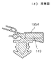
図10において、第1のガスケット135のうち上辺ガスケット部135a、縦辺ガスケット部135b、下辺ガスケット部135cの断面形状は図11に示す形状であり、上辺ガスケット部135a、下辺ガスケット部135cの一端から垂直方向にわずかに延びた延出部135dの断面形状は図12に示す形状となっている。また、延出部135dの端面形状(斜線部)は図13に示す形状である。
10, the cross-sectional shapes of the
図11において、141は磁化されたマグネットであり、第1のガスケット135の全辺に挿入されている。上辺ガスケット部135のマグネット141の下部には空気層142があり、アンカー部143が形成されている。143aは外向きに突出した係合片である。空気層142の端面はマグネット141の端面より出っ張って湾曲しており扉閉時の衝撃を吸収できるようになっている。上辺ガスケット135a、縦辺ガスケット部135b、下辺ガスケット部135cは軟質部材(本実施の形態の場合は軟質塩ビ)で形成されている。
In FIG. 11,
図12において、延出部135dでマグネット141の下部にある空気層144の端面は、マグネット141の端面と同面に成形されている。また扉の所定の位置に係合されるアンカー部145には先端近傍に第1の係合片146を形成し、基部147と第1の係合片146の間には第2の係合辺148が形成されている。延出部135dは上辺ガスケット135a、縦辺ガスケット部135b、下辺ガスケット部135cと同様に軟質部材で成形されているが、基部147と第2の係合辺148は硬質部材(本実施の形態の場合は硬質塩ビ)で成形されている。
In FIG. 12, the end surface of the
図13は延出部135dの端面を示しており、端面は溶着された溶着面149を形成している(斜線図)。
FIG. 13 shows an end face of the extending
また、図4は扉108が閉じた状態の第2のガスケット134と第1のガスケット135の関係を表した図である。この状態では第2のガスケットの貯蔵室側に位置する空気層134bの側面に位置する第2のヒレ部133bと第1のガスケットのマグネット141を内包する面とにおいて、第1のガスケット135の延出部135dの長さに亘って圧接した状態で維持されている。
FIG. 4 is a view showing the relationship between the
なお、扉108の表面には冷蔵庫の設定温度などを設定する設定機能や運転状況や食品に関する情報などを表示させる表示機能を備えた操作パネル108aが備えられている。
The surface of the
以上のように構成された扉装置を備えた冷蔵庫について、以下その動作を説明する。 About the refrigerator provided with the door apparatus comprised as mentioned above, the operation | movement is demonstrated below.
図5のように観音開き式扉107,108が両方とも閉塞状態にあるときはバネ部材137a,137bの復元力によって第2のガスケット134の表面は互いに密着状態となって冷蔵室105aをシールし、さらに、第2のガスケットの第1のヒレ部133aが扉側板の凹部のオーバーハング部114d,115dと内側より当接し、第2のヒレ部133bが平面部114b、115bの表面と当接することすることにより扉側板の凹部114a,115a内を通じて庫内外の空気が連通することがなくなり、庫外と冷蔵室105a間をシールし外気熱の侵入や冷気漏れを防止することができる。
When the
また、第2のガスケット134内に内蔵された異極同士のマグネット134aの接合により第2のガスケット134は互いに吸着状態となるため冷蔵室105aのシール性を高めることができる。マグネット134aは第2のガスケット134内で冷蔵室105a側から空気層134bを複数個連続して備えられるので冷蔵室105aの冷気でマグネット134aが直接冷やされることはなく、したがって結露などの問題を回避できる。
Further, since the
また図5のように扉閉状態になった時、庫外側にあるマグネット134aの接合により、貯蔵室側の空気層134bは、逆に離れ勝手になる傾向があるが、高さ約1mmの突片134dによって第2のガスケット134間に生じる隙をシールして冷蔵室105a内の冷気が隙間に侵入するのを防ぐことができ、第2のガスケット134の周辺に結露が生じるのを防止することができる。
In addition, when the door is closed as shown in FIG. 5, the
次に図7に示すように、扉107を開けていくと、やがて保持部材129はラッチ部125の傾斜面123がガイド部の突部110に沿った動作を行うため、回動軸127を支点にして回動する。これにより第2のガスケット134は互いの密着状態が強制的に解除されることにより扉開時において第2のガスケット134の表面が互いにこすれることがなくなり、ガスケットの耐久強度が向上する。また、ガスケット表面がこすれて静電気が発生し汚れが付着することもなくなる。また、こすれによる摩擦音の発生もなくなる。さらには、扉開放力を低減することができ使用者の使い勝手の向上が図れる。
Next, as shown in FIG. 7, when the
また、図8に示すように第2のガスケット134に備えられたマグネット134aは閉扉状態で両扉のヒンジ106を結ぶ線上に位置しているので可動ガスケット134の閉状態において効果的にマグネット134aの当接部を圧接してシール性を高めることができる。
Further, as shown in FIG. 8, the
そしてさらに扉107を開けていくとバネ部材137aの復元力によって傾斜面121がガイド部109の突部110に沿った動作を行うため、回動軸127を支点にして保持部材129は扉閉塞状態と同じ状態に復帰する。これにより扉側板111と保持部材129との間に異物が入り込む事がなくなる。これは扉閉塞状態においても同じことが言える。
When the
次に、扉107を閉めていくと、傾斜面121と傾斜面123がガイド部の突起部110に沿った動作を行うことにより、扉開けていく状態と同様の効果が得られる。
Next, when the
また、図6のように扉が閉塞状態、開放状態の両状態時において回動軸127,128は外れ防止部材131,132によって固定されている。これにより、バネ部材137a,137bの復元力により保持部材129,130が扉側板114、115から外れることなく安定しスムーズな回動が得られる。
Further, as shown in FIG. 6, the rotating
また回動軸127,128は扉側板114,115に囲まれ扉107,108内で貯蔵室45a側に配置されるので、第2のガスケット134は扉開閉動作に応じてガスケット当接面をこじて強く摺動させることなく動作させることができるのでガスケットの信頼性を確保でき、余分な力を加えることなく扉開閉を実現することができる。
Further, since the
またこのとき、ガスケット同志の当接面の肉厚を当接しない面の肉厚より厚くして、摺動による当接面の破損を防止しシール性の確保を行うことが出来る。 At this time, the thickness of the abutting surfaces of the gaskets can be made thicker than the thickness of the non-abutting surface to prevent the abutting surface from being damaged by sliding and to ensure the sealing performance.
なお、可動型の第2のガスケットの回動軸127,128,保持部材129,130、外れ防止部材131,132などの回動機構が扉側板の凹部114a,115a内に収容されているため扉107,108の厚み内に収まり、庫内側の有効スペースを侵害したり、庫外に突出して邪魔になることもない。
Note that the rotation mechanism such as the
また、図9には扉108の分解図を表している。扉108の組立て工程において扉外板112に上キャップ112a、下キャップ112b、扉側板115を所定の位置に固定し外板112内に発泡断熱材118を注入して、扉内板117を上から嵌め、冶具で固定される。この時、扉側板115に備えられたガイドリブ115cによって突出部117bが所定の位置に係合される。
FIG. 9 shows an exploded view of the
また真空成形される扉内板117は従来の扉内板と異なって、扉側板115が扉内板117と係合される。この時、扉側板115の側面形状によって扉内板117をそれにあった形状にトリミングする必要がある。上記のように扉内板117を扉側板115と接合するために第1の周縁部117cと第2の周縁部117dは段差を介して連続する部分が生じる。そこで扉内板117の成形時、真空成形された扉内板117の外枠を順にトリミングしていくが、この段差の角度を例えば90度すなわち第1の周縁部117cと第2の周縁部117dが直角に連通している場合、トリミング後の扉内板117のトリミング部分はバリが生じたり非常に煩雑な状態になる。成形後の品質状態を確保するにはこの段差の角度を45度以下でトリミングすれば上記のようにバリが生じたりすることがなく、精度よく接合が可能となる。
Also, the door
その後、成形された扉108には化粧部材138が係止具139によって固定され、扉107,108を閉じたときの突出部56b、57b間の隙を狭めることができる。これによってこの間を循環する冷気によって第2のガスケット134が冷やされるのを低減することができ、第2のガスケット134の結露防止や吸熱量の低減を図ることができる。同時に化粧部材138は扉側板114,115を表面から覆うので凹凸の形状のある外観を覆って意匠的に見栄えをよくすることができる。
After that, the
また、図12のよう空気層144の側端面は、マグネット141の側端面と面一に成形されていることで、第2のガスケット134との間に隙間が形成されないよう配慮されているので図4に示すように、第2のガスケット134と第1のガスケットの延出部135dは第2のヒレ部133bとマグネット141、空気層144の側端面とが圧接して構成されている。これにより第2のガスケット134と第1のガスケットの延出部135dの間から冷気が漏れることはなく、冷蔵室105a内をシールすることができる。
Further, as shown in FIG. 12, the side end surface of the
また、扉閉時は圧接、扉開放時は非接触を繰り返す頻度の高い所に第2のヒレ部133bのように柔軟性がある部分で対応しているので、扉開閉を繰り返されても破れや破損等が起こることはなく、ガスケットの耐久信頼性を高めることができる。
In addition, the flexible part such as the
また基部147と第2の係合片148は硬質塩ビなどの硬質部材で成形され、さらにアンカー部145には上下に第1の係合片146,第2の係合片148の2段の係合片が形成されているので、延出部135dのように寸法が短い場合でも、扉の所定の位置に挿入されたアンカー部145は外れることはない。また、第1の係合辺146は軟質部材で成形されているので、取付け挿入時の作業性がよい。
Further, the
上辺ガスケット部135a,縦辺ガスケット部135b,下辺ガスケット部135c,延出部135dはそれぞれ端面を繋いで、内部にマグネット141を挿入して溶着している。図13のように延出部135dの端面は軟質部材(本実施の形態の場合は軟質塩ビ)で端面溶着して塞いでいるので、内部に挿入されたマグネット141を保持し、空気層を密封できる。
The upper
また、図1と図6に示すようにヒーター線140は扉107に配設されているので、第2のガスケット134に生じる結露やフランジ113付近に生じる結露を防止することができる。そして扉107のヒーター線140に対して操作パネル108aは扉108に備えられている。これにより交流電源によるヒーター線140と操作パネル108aに配設される直流電源によるリード線(図示しない)とを分離することができ、この間に生じやすい交流から直流に対するノイズによる操作パネル108aへの誤動作障害を無くすことが出来る。
Further, as shown in FIG. 1 and FIG. 6, the
このように、従来のシール構造に比べて簡素な構成となるためコスト的に安価にまとめることができる。また、確実な密着シール構造が実現できるためガスケットを通じての熱通過量を低減することができ、侵入熱量の低減による電力消費の低減やガスケット周辺の結露防止による品質向上を図ることができる。併せて、ガスケットの摩擦,摺動による耐久信頼性を高めることができる。 Thus, since it becomes a simple structure compared with the conventional seal structure, it can summarize at low cost. In addition, since a reliable tight seal structure can be realized, the amount of heat passing through the gasket can be reduced, power consumption can be reduced by reducing the amount of intrusion heat, and quality can be improved by preventing condensation around the gasket. In addition, the durability and reliability due to the friction and sliding of the gasket can be enhanced.
そして、以上の構成、動作により従来、扉間に設けられていた仕切体を廃止することができる。それにより冷蔵室105aの間口が広く利用でき、冷蔵室105a内の食品収納スペースや扉裏面の扉収納部116a,117aの収納スペースが増大し使用者の使い勝手や収納性の向上が図れる。また、仕切体がなくなるので扉間の隙が一対の第2のガスケット134の厚さのみとなるので吸熱量の低減を図ることができる。
And the partition body conventionally provided between the doors by the above structure and operation | movement can be abolished. Thereby, the frontage of the
また、第2のガスケットのマグネット134aと回動軸127,128間の距離に対して回動軸127,128と冷蔵室105aに設けた突起部110間の距離を大きくしたので、回動軸127,128を支点にしたてこの原理で軽い力で扉107,108を開放することができる。前述のこの距離比を約2倍に設定すれば本実施の形態のように収納負荷が多く且つ重量も重いために開閉に力を要する冷蔵室において、扉開閉の軽さと開閉の安定感が適度にバランスし操作性のよい扉装置が提供できる。
In addition, since the distance between the
さらに、第2のガスケット134の相互の密着状態を確保するために扉全体を開閉時に変位させる必要がなく、そのためにヒンジ機構が複雑になって耐久信頼性が低下したりコスト的にも高価につくことがない。また、使用者の操作時に扉全体を変位させることによる操作感の重さや動作の不安感が解消される。
Further, it is not necessary to displace the entire door at the time of opening and closing in order to secure the close contact state of the
また、最上部の貯蔵室である冷蔵室105aにこの扉装置を設けることによって、使用者が対面して見渡せる使用頻度の高い貯蔵室の広々感が向上し、使い勝手を一段と高めることができる。
Further, by providing this door device in the
また、ラッチ部125,126に対するガイド部109を冷蔵室105a内の上面に設けたので、冷蔵室105a内への物品の出し入れの邪魔にならず、収納性に影響を及ぼすことがない。
Further, since the
また、以上の構成、動作を片側の扉のみに設けた場合は第2のガスケット134が回動するために必要な構成部品が半減できることで組み立て性の向上、材料費の低減を図ることができる。
Further, when the above configuration and operation are provided only on one door, the number of components necessary for the
なお、本実施の形態において第2のガスケット134は二つの観音開き式扉107,108間に設けたが、二つの引き出し式扉間に設けることによって同様の効果が得られ、引き出し扉間の仕切体を廃止することができ、引き出し扉と一体に出入りする収納容器の上下方向の有効寸法を拡大して食品収納スペースを増大させることができる。
Although the
(実施の形態2)
図14は、本発明の実施の形態2による冷蔵庫の外観正面図である。図15は同実施の形態の冷蔵庫の扉を外した状態の斜視図である。図16は、同実施の形態の扉装置の裏面斜視図である。図17は図14のC−C線断面図である。図18は図16の点線で示した要部拡大図である。図19は図17の開閉動作を示す断面図である。
(Embodiment 2)
FIG. 14 is an external front view of the refrigerator according to the second embodiment of the present invention. FIG. 15 is a perspective view of the refrigerator of the same embodiment with the door removed. FIG. 16 is a rear perspective view of the door device of the embodiment. 17 is a cross-sectional view taken along the line CC of FIG. 18 is an enlarged view of a main part indicated by a dotted line in FIG. 19 is a cross-sectional view showing the opening / closing operation of FIG.
図14から図18において301は冷蔵庫本体であり、鋼鈑製の外箱302と樹脂製の内箱303と、両箱302、303間に充填される図示しない発泡断熱材とから前方に開口した断熱箱体304を構成し、上段より冷蔵室305a、野菜室305b、冷凍室305cがあり、上段の冷蔵室305aは左右縁部に上下ヒンジ306により回動自在に枢支された2つの観音開き式扉307,308によって開閉自在に構成されている。
14 to 18,
扉307,308は扉外板309、310と扉307,308の非枢支側の側面に取付けられた扉側板311、312と扉内板313、314と、外板309、310と側板311、312及び内板313、314間にそれぞれ発泡充填された発泡断熱材118とから構成されている。
The
扉側板311、312は外板309、310から扉307、308の非枢支側に向かって内板313、314に亘って形成され、室外側に段差部311a、312bを有している。また315、316は内板313、314によって扉307,308の裏面室内側に形成した扉収納部である。
The
317は冷蔵室305aの開口部前縁であり、318は開口部前縁317に密着する第1ガスケットである。第2ガスケット319は軟質の合成樹脂(実施例の場合、塩化ビニル)であり、扉307、308の対向する一側面に配置し閉扉時、相互に密着する。
319aは第2ガスケット319内に複数個備えられた空気層である。320、321は硬質の合成樹脂(実施例の場合、塩化ビニル)で成形された基部であり、第2ガスケット319と押出し成形で一体に成形されている。319bは第2ガスケット319のマグネットであり、庫外側に最も近い空気層319aに内包されている。また基部320と第2ガスケット319はマグネット319bを内包する空気層319aで接続する接続部320a、321aを有している。
A plurality of air layers 319 a are provided in the
そしてマグネット319bは第2ガスケット319内でN極、S極の順序が互いに異なるように収納されており、すなわち図17の状態で第2ガスケット319が向かいあったときN極、S極が互いに向かい合うように収納されている。
The
322、323は基部320、321と一体成形された軟質の合成樹脂(実施例の場合、塩化ビニル)の第1のヒレ部であり、段差部311a、312aに接している。
324、325は基部320、321を回動させる回動軸であり軸部材324a、325aを挿通して段差部311a、312a内に備えられている。また基部320、321は冷蔵室305aの開口部を上下に渡る寸法で延在しており、回動軸324、325を中心にして段差部311a、312a内で回動自在に支持される。
ハンドル326、327は取手部326a、327aと作用部326b、327bで構成され断面略L字状に形成されており、扉307、308の非枢支側で扉高さの中央部から下部に渡って形成されている。また作用部326b、327bは基部320、321に一体成形された軟質の合成樹脂(実施例の場合、塩化ビニル)で形成された第2のヒレ部328、329と接している。第2のヒレ部328、329は基部320、321を介して第1のヒレ部322、323と反対側に備えられている。
330,331は回転軸であり、コイルバネからなるバネ部材332、333が挿通され、一端を扉側板311、312に、他端を作用部326b、327bに接している。334、335は第1の化粧板であり、内板313、314の上下に亘る寸法で扉側板311、312の間に備えられている。336,337は断熱材118内に埋設された扉側板311,312の前部で外板309、310を介して配置された第2の化粧板である。
図18で310aは外板310の上部に嵌められた上キャップであり、第2ガスケット319の上端は上キャップ310a内に係合支持されている。そして第2ガスケット319の裏面には上部近傍から上端部にかけて支持部材338が配置され第2ガスケット319に密着固定されている。実施例の場合、支持部材338はPP樹脂で形成され、接着剤で固定されているが、ABS樹脂やその他樹脂材料でもよく、また硬質の合成樹脂(例えば塩化ビニルなど)を第2ガスケット319の裏面に一体成形してもよい。また第1ガスケット318と支持部材338が重なる部分を密着固定すればなお良い。
In FIG. 18,
また、図18では扉308で説明したが上記の構造は扉307側にも形成されるものである。
Further, although the
以上のように構成された冷蔵庫について、以下動作を説明する。 The operation of the refrigerator configured as described above will be described below.
扉307、308が両方とも閉塞状態にあるときは第2ガスケット319は互いに密着状態となり冷蔵室305a内をシールすることができる。また第1のヒレ部322,323と第2のヒレ部328、329の2段のシール構造で冷蔵室305a内の冷気が段差部311a、312a内に侵入しても冷蔵室305aをシールすることができる。
When the
次に図19のように扉307をハンドル326の取手部326aに手をかけて手前に引張って開けて行くと回転軸330を中心に矢印のように可動し、作用部326bが第2のヒレ部328を圧接し、基部320を回動軸324を中心に回動させて第1のヒレ部322を段差部311aに押し当て第2のガスケット319をシール状態から引き離して行く。
Next, as shown in FIG. 19, when the
この時、扉307側の第2ガスケット319は接続部320aに引張られてマグネット319bが対向するマグネットから引き離されるので、ハンドル326に連動して開扉動作を行うことができるので操作性がよい。
At this time, the
また、第2ガスケット319は基部を硬質材で形成しているので保持力が強く、回動軸324内に軸部材324aを挿通しているので第2ガスケット319の支持強度を高めてスムーズに回動させることができる。硬質材であるため回動軸324の加工形成が容易である。
Further, since the
なお、第2ガスケット319の基部にハンドルの作用部が当接する端部は、回動軸324が設けられた反対側の端部に設定されるため、ハンドルの回転動作によりてこの原理で容易に第2ガスケット319を動かせる。
Note that the end of the
そして使用者は取手部326aをさらに手前に引いていくと対向していたマグネット319b内の相対向する極性が同極になるので、互いのマグネット319bは反発しあい可動するハンドル326の上下方向の範囲内でシールが解除される。そしてさらに扉307を手前に引張って行くとハンドル326より上方部のガスケット319が扉308からシールが解除され、扉307を開くことができる。
When the user pulls the
そしてハンドル326から手を離すとバネ部材332の復元力によって、ハンドル326は元の状態に戻る。
When the hand is released from the
次に扉307を閉じて行くとマグネット319bはお互い同極同士が近づくので反撥しあうので第2のガスケット307、308の表面がこすれることがなくなる。そしてさらに閉じて行くとお互い異極が相対向し、冷蔵室305aのシールをすることができる。
Next, when the
また扉閉時において、支持部材338を備えたことで、例えば外気温度が高い状態など第2ガスケット319の空気層319aが膨張して、第2ガスケット307、308の倒れ込みを防止し、スムーズに扉開閉を行うことができる。
In addition, when the door is closed, the
そして以上の動作よりハンドル326自身を可動させることで直接第2ガスケット319の密着状態を解除し扉307、308を開放することができるため使用者は扉操作を楽に行うことができる。
Further, by moving the
101,301 冷蔵庫本体
104,304 断熱箱体
105a 冷蔵室
106 ヒンジ
107,108,307,308 扉
108a 操作パネル
110 突起部
114,115 扉側板
114a,115a 凹部
114c、115c ガイドリブ
114d,115d オーバーハング部
116,117 扉内板
116b、117b 突出部
117c 第1の周縁部
117d 第2の周縁部
115,116 ラッチ部
127,128 回動軸
129,130 保持部材
133a,322,323 第1のヒレ部
133b,328,329 第2のヒレ部
134,319 第2のガスケット
134a マグネット
134b 空気層
134d 突片
135,318 第1のガスケット
135d 延出部
138 化粧部材
140 ヒーター線(加熱体)
145 アンカー部
146 第1の係合片
148 第2の係合片
149 溶着面
311a,312a 段差部
317 開口部前縁
319a 空気層
319b マグネット
320,321 基部
324,325 回動軸
324a,325a 軸部材
326,327 ハンドル
326a,327a 取手部
326b,327b 作用部
330,331 回転軸
101, 301
145
Claims (5)
Priority Applications (1)
| Application Number | Priority Date | Filing Date | Title |
|---|---|---|---|
| JP2005113240A JP3983773B2 (en) | 2000-11-06 | 2005-04-11 | Door device and refrigerator provided with door device |
Applications Claiming Priority (2)
| Application Number | Priority Date | Filing Date | Title |
|---|---|---|---|
| JP2000337116 | 2000-11-06 | ||
| JP2005113240A JP3983773B2 (en) | 2000-11-06 | 2005-04-11 | Door device and refrigerator provided with door device |
Related Parent Applications (1)
| Application Number | Title | Priority Date | Filing Date |
|---|---|---|---|
| JP2001336344A Division JP3682015B2 (en) | 2000-11-06 | 2001-11-01 | Door device and refrigerator provided with door device |
Publications (2)
| Publication Number | Publication Date |
|---|---|
| JP2005207736A JP2005207736A (en) | 2005-08-04 |
| JP3983773B2 true JP3983773B2 (en) | 2007-09-26 |
Family
ID=34913790
Family Applications (1)
| Application Number | Title | Priority Date | Filing Date |
|---|---|---|---|
| JP2005113240A Expired - Fee Related JP3983773B2 (en) | 2000-11-06 | 2005-04-11 | Door device and refrigerator provided with door device |
Country Status (1)
| Country | Link |
|---|---|
| JP (1) | JP3983773B2 (en) |
Families Citing this family (3)
| Publication number | Priority date | Publication date | Assignee | Title |
|---|---|---|---|---|
| JP6057563B2 (en) * | 2012-06-29 | 2017-01-11 | アクア株式会社 | refrigerator |
| CN103162500B (en) * | 2013-04-03 | 2015-05-13 | 合肥美的电冰箱有限公司 | Refrigerator |
| JP7266164B2 (en) * | 2019-08-06 | 2023-04-28 | パナソニックIpマネジメント株式会社 | refrigerator |
-
2005
- 2005-04-11 JP JP2005113240A patent/JP3983773B2/en not_active Expired - Fee Related
Also Published As
| Publication number | Publication date |
|---|---|
| JP2005207736A (en) | 2005-08-04 |
Similar Documents
| Publication | Publication Date | Title |
|---|---|---|
| JP3679003B2 (en) | Refrigerator door opener | |
| JP5269720B2 (en) | refrigerator | |
| JP3682015B2 (en) | Door device and refrigerator provided with door device | |
| JP2004353943A (en) | Refrigerator | |
| JP2003121061A (en) | Door devices such as refrigerators | |
| JP4768325B2 (en) | Door open prevention device for refrigerator | |
| JP3983773B2 (en) | Door device and refrigerator provided with door device | |
| JP6073199B2 (en) | refrigerator | |
| JP2003114087A (en) | Refrigerator door device | |
| JP6078433B2 (en) | refrigerator | |
| JP4608840B2 (en) | Door device and refrigerator | |
| US12578139B2 (en) | Refrigerator | |
| US12270596B2 (en) | Refrigerator | |
| JPWO2002004779A1 (en) | Door device and refrigerator | |
| JPH09196548A (en) | Storage | |
| JP2004245523A (en) | Sealing device for storage vessel and assembly method for sealing device for storage vessel | |
| JP2004293912A (en) | refrigerator | |
| JPH0737874B2 (en) | Storage | |
| JPH0953877A (en) | Door structure of storage box | |
| JP3869806B2 (en) | Storage door device | |
| JP2001116431A (en) | Refrigerator | |
| US20230243575A1 (en) | Refrigerator | |
| JP3313551B2 (en) | Storage door structure | |
| JP2003021455A (en) | refrigerator | |
| JP2019113201A (en) | refrigerator |
Legal Events
| Date | Code | Title | Description |
|---|---|---|---|
| RD01 | Notification of change of attorney |
Free format text: JAPANESE INTERMEDIATE CODE: A7421 Effective date: 20050622 |
|
| A131 | Notification of reasons for refusal |
Free format text: JAPANESE INTERMEDIATE CODE: A131 Effective date: 20070313 |
|
| A521 | Written amendment |
Free format text: JAPANESE INTERMEDIATE CODE: A523 Effective date: 20070509 |
|
| TRDD | Decision of grant or rejection written | ||
| A01 | Written decision to grant a patent or to grant a registration (utility model) |
Free format text: JAPANESE INTERMEDIATE CODE: A01 Effective date: 20070605 |
|
| A61 | First payment of annual fees (during grant procedure) |
Free format text: JAPANESE INTERMEDIATE CODE: A61 Effective date: 20070704 |
|
| FPAY | Renewal fee payment (event date is renewal date of database) |
Free format text: PAYMENT UNTIL: 20100713 Year of fee payment: 3 |
|
| R150 | Certificate of patent or registration of utility model |
Free format text: JAPANESE INTERMEDIATE CODE: R150 |
|
| FPAY | Renewal fee payment (event date is renewal date of database) |
Free format text: PAYMENT UNTIL: 20100713 Year of fee payment: 3 |
|
| S111 | Request for change of ownership or part of ownership |
Free format text: JAPANESE INTERMEDIATE CODE: R313111 |
|
| FPAY | Renewal fee payment (event date is renewal date of database) |
Free format text: PAYMENT UNTIL: 20100713 Year of fee payment: 3 |
|
| R350 | Written notification of registration of transfer |
Free format text: JAPANESE INTERMEDIATE CODE: R350 |
|
| FPAY | Renewal fee payment (event date is renewal date of database) |
Free format text: PAYMENT UNTIL: 20110713 Year of fee payment: 4 |
|
| LAPS | Cancellation because of no payment of annual fees |