JP3967902B2 - Chair - Google Patents
Chair Download PDFInfo
- Publication number
- JP3967902B2 JP3967902B2 JP2001311077A JP2001311077A JP3967902B2 JP 3967902 B2 JP3967902 B2 JP 3967902B2 JP 2001311077 A JP2001311077 A JP 2001311077A JP 2001311077 A JP2001311077 A JP 2001311077A JP 3967902 B2 JP3967902 B2 JP 3967902B2
- Authority
- JP
- Japan
- Prior art keywords
- frame
- chair
- adjusting
- lock
- seat
- Prior art date
- Legal status (The legal status is an assumption and is not a legal conclusion. Google has not performed a legal analysis and makes no representation as to the accuracy of the status listed.)
- Expired - Fee Related
Links
- 239000000725 suspension Substances 0.000 claims description 23
- 238000003466 welding Methods 0.000 description 4
- 239000000463 material Substances 0.000 description 3
- 230000000284 resting effect Effects 0.000 description 3
- NJPPVKZQTLUDBO-UHFFFAOYSA-N novaluron Chemical compound C1=C(Cl)C(OC(F)(F)C(OC(F)(F)F)F)=CC=C1NC(=O)NC(=O)C1=C(F)C=CC=C1F NJPPVKZQTLUDBO-UHFFFAOYSA-N 0.000 description 2
- 230000000694 effects Effects 0.000 description 1
- 238000000034 method Methods 0.000 description 1
- 230000002093 peripheral effect Effects 0.000 description 1
- 239000011347 resin Substances 0.000 description 1
- 229920005989 resin Polymers 0.000 description 1
Images


Landscapes
- Chairs For Special Purposes, Such As Reclining Chairs (AREA)
Description
【0001】
【発明の属する技術分野】
本発明は椅子に関するもので、特に背もたれを後方へ倒すことにより座席が前方へ移動するリクライニング椅子に関する。
【0002】
【従来の技術】
従来、前記のようなリクライニング椅子において、その座席を前後方向に移動可能に支承する構造として、椅子の固定フレーム上にレールを前後方向に設け、該レール上に座席を摺動可能に載置する方法が知られている。
【0003】
【発明が解決しようとする課題】
前記従来のようにレール上に座席を摺動可能に載置する構造においては、その摺動摩擦抵抗が大きいため、通常の着座姿勢からリクライニング姿勢にする際のもたれ力及びリクライニング姿勢から通常の着座姿勢に戻す際の戻し力が大きくなる。
【0004】
そのため、特に老人のように力の弱い使用者においてはリクライニング姿勢から起き上がりにくい問題がある。
【0005】
そこで本発明は、座席の移動力を調整する調整機構を有するものにおいて、その調整機構をフリーにした場合に、座席の前後方向の移動を、前記従来のレール方式に比べて軽くし、特に力の弱い老人等においても容易に起き上がることができる椅子を提供することを目的とするものである。
【0006】
【課題を解決するための手段】
前記の課題を解決するために、請求項1記載の第1の発明は、椅子の後部に固定した支軸により椅子の前後方向に回転可能に備えられるとともに前記支軸より上方と下方へ延びた背フレームと、上部が固定部に軸により回転可能に連結されて垂設され、上部を中心として前後方向に揺動する吊り部材と、該吊り部材の下部と前記背フレームの下部に回転可能に連結されて略水平状態に設けられた座フレームと、前記吊り部材の揺動に対する抵抗力を調整する調整手段を有する椅子であって、
前記調整手段を、前記吊り部材に、該吊り部材とともに移動する調整部材を設け、固定部材に、前記調整部材を摺動可能に挟持する挟持部材を設け、固定部材に体調つまみを設け、該体調つまみの操作により前記挟持部材による前記調整部材の挟持力を調整するように構成したことを特徴とするものである。
【0007】
本発明において、調整手段により吊り部材の揺動に対する抵抗力を、使用者に適した量に調整することにより、使用中にみだりに座席や背もたれが動くことを防止できる。
【0008】
また、調整手段による抵抗力をなくして吊り部材の揺動を自由にすることにより、座席は吊り部材によって振り子式に自由に揺動する。このように座席を吊り保持して振り子式に揺動させることにより、前記従来のような座席をレールで支承するものに比べて座席の移動に対する抵抗力が小さくなる。
【0009】
請求項2記載の第2の発明は、前記第1の発明において、前記吊り部材が、その上部を、固定の肘フレームの下部に設けた軸に回転可能に連結して設けられていることを特徴とするものである。
【0010】
請求項3記載の第3の発明は、前記第1又は第2の発明において、前記調整部材及び挟持部材を板状に形成したことを特徴とするものである。
請求項4記載の第4の発明は、前記第1乃至3のいずれかの発明において、前記調整手段を、前記座フレームの上部に設けたことを特徴とするものである。
請求項5記載の第5の発明は、前記第1乃至4のいずれかの発明において、前記座フレームを、その前方が後方より上方に位置するように傾斜させたことを特徴とするものである。
【0011】
【発明の実施の形態】
図に示す実施例に基づいて本発明の実施の形態について説明する。
【0012】
図1及び図2において、1は椅子の台座で、該台座1上に回転台2が水平面において回転可能に備えられている。該回転台2の両側に位置して図2に示すように側枠3が起立固着され、該両側枠3の上端に肘部を構成する部材、図の例では板状の肘板4が椅子の前後方向に配置されて固着されている。
【0013】
前記両肘板4における前後方向の略中央部の下面には軸受5が固設されているとともに該軸受5に支軸6が左右方向に水平に設けられ、該支軸6に吊り部材7の上端部が回転可能に連結され、吊り部材7が、支軸6を中心として下部が前後方向に揺動するように回転可能に備えられている。該吊り部材7の下端部には、座席を構成する部材である座フレーム8が配置されている。
【0014】
座フレーム8における前後方向の略中央部の下面には座受金具9が固設され、該座受金具9に前記吊り部材7の下端部が左右方向に水平のピン10により回転可能に連結されて、座フレーム8が吊り部材7で支承されている。したがって、座フレーム8は吊り部材7によって吊り下げられた状態で振り子式に前後方向へ移動するようになっている。なお、前記座フレーム8は図2に示すように椅子の左右に設けられ、両側に備えた前記吊り部材7によって支持されている。また、左右の座フレーム8は相互に連結棒11で連結されている。
【0015】
前記肘板4の後端には軸受12が溶接などにより固設され、該軸受12に支軸13が、椅子の左右方向において水平に配置して固設されている。そして、該支軸13に、背もたれを構成する背フレーム14が回転可能に備えられ、背フレーム14が支軸13を中心として椅子の前後方向に回転するようになっている。更に、該背フレーム14は、前記支軸13部を境として上方へ延びた上部フレーム14aと、下方へ延びた下部フレーム14bとが一体形成され、その下部フレーム14bの下端が前記座フレーム8の後端部に設けた水平の連結ピン15により回転可能に連結されて、座フレーム8の後部を支持している。
【0016】
前記背フレーム14は、図2に示すように椅子の左右に配置され、夫々が前記の構造によって前記の肘板4の後部に回転可能に支持され、かつ、前記の左右の座フレーム8における後部を支持している。
【0017】
以上の構成により、背フレーム14の上部フレーム14aを図1において後方(矢印A方向)へ傾倒すると、下部フレーム14bが前方(矢印A1方向)へ移動して座フレーム8を矢印A2方向へ前進移動させ、また、上部フレーム14aを前方(矢印B方向)へ起立させると、下部フレーム14bが後方(矢印B1方向)へ移動して座フレーム8を矢印B2方向へ後退移動させるようになっている。
【0018】
次に各部の構造の詳細について説明する。
【0019】
前記両肘板4における前後方向の略中央部、すなわち前記吊り部材7の後方近傍の下面には、図3及び図4に示すような逆U字型の体調つまみ取付金具16がスポット溶接などにより固着されて垂設されている。該体調つまみ取付金具16の下端部には図4に示すように、椅子の左右方向に水平に配した軸受16aが固設され、該軸受16aにボルト17が遊嵌されている。該ボルト17の内側端17aには押え部材18が、かしめや溶接等により固着されている。
【0020】
前記押え部材18と前記体調つまみ取付金具16との間には、樹脂等の摩擦抵抗が大きい材質からなり、図5に示す側面形状の3個の挟持部材19が配置され、更に該3個の挟持部材19の間に図3に示すような長孔21aを形成した2個の調整部材21が挟まれて配置されている。前記押え部材18と挟持部材19と調整部材21は夫々板状に形成されている。
【0021】
前記調整部材21の先部は前記吊り部材7にピン22により回転可能に連結され、後部は自由端になっている。
【0022】
そして、前記両挟持部材19に形成した穴19aと、前記調整部材21に形成した長孔21aに前記のボルト17を遊嵌状に貫通させて挟持部材19と調整部材21がボルト17に支承されている。
【0023】
前記押え部材18の上部には回転防止用ボルト23が備えられており、該回転防止用ボルト23を前記挟持部材19の上部に形成した穴24に遊嵌するとともに前記体調つまみ取付金具16に螺着して、ボルト17、押え部材18、挟持部材19がボルト17の軸心を中心として回転しないようにしてある。
なお、前記調整部材21を1枚にし、この1枚の調整部材21を2枚の挟持部材19で挟持してもよい。前記実施例のように調整部材21を2枚とし、挟持部材19を3枚にすると、調整部材21の制動面積を多くして座フレーム8の揺動の調整を容易にすることができる。
【0024】
前記ボルト17の外側端には体調つまみ26が備えられている。該体調つまみ26内の軸心部には取付穴27が形成されており、該取付穴27の先部外周に当接部28が設けられ、取付穴27の後部外周にナット29が埋設固着されている。そして、該体調つまみ26が、そのナット29によって前記ボルト17の外側端部に螺着されている。
【0025】
以上の構造により、体調つまみ26を締付け方向に回転すると、その当接部28が体調つまみ取付金具16の外面にプレート30を介して当接し、ボルト17がナット29によって体調つまみ26側へ引き寄せられ、押え部材18が挟持部材19と調整部材21を体調つまみ取付金具16側へ押し付ける。したがって、体調つまみ26の締付け度合(量)を大きくすると挟持部材19と調整部材21との摩擦抵抗が大きくなって、調整部材21の摺動に対する抵抗力が大きくなり、また、体調つまみ26を緩めると調整部材21の摺動に対する抵抗力が小さくなる。
【0026】
前記体調つまみ26、ボルト17、挟持部材19、調整部材21などにより、前記座フレーム8を前後方向にスライドできる力を調整する機構を構成するもので、これらを、吊り部材の揺動に対する抵抗を調整する調整手段31とする。この調整手段31は図2に示すように椅子の左右に設けられている。
【0027】
次に前記軸受12部の周辺構造について図7及び図8により説明する。
【0028】
図7は図1におけるM−M線拡大断面図、図8は図7におけるN−N線断面図である。
【0029】
図7において、4は前記の肘板を示すもので、この肘板4の後端に軸受12が固設されている。該軸受12には支軸13が椅子の左右方向において水平に配置されているとともに該支軸13は、その外側端を軸受12内に嵌入してピン32により軸受12に固定して回転不能に備えられている。該支軸13の内側端には前記の背フレーム14が回転可能に備えられている。
【0030】
前記支軸13における軸受12と背フレーム14との間における前記支軸13の外周にはロック筒33が回転可能に遊嵌されており、該ロック筒33の外側端は前記軸受12内に回転可能に嵌入され、内側端にはロック用リンク34が溶接などにより固設されている。該ロック用リンク34は図8に示すように、ロック筒33、すなわち支軸13から上方へ向って配置され、その上方端に係止ピン35が、前記背フレーム14の前側(前面)を横断するように設けられている。該係止ピン35の他端には、前記背フレーム14に略平行に配置した連結リンク36の下部がピン37により回転可能に連結されている。
【0031】
図1において、前記背フレーム14の上部には枕フレーム38がピン39により回転可能に備えられ、該ピン39を中心として枕フレーム38が前後方向に起倒可能に備えられている。該枕フレーム38の下部にはリンク40が前側へ突出して固設されており、該リンク40の前部に前記連結リンク36の上部がピン41により回転可能に連結されている。
【0032】
前記軸受12、支軸13、ロック筒33、ロック用リンク34、係止ピン35、連結リンク36、枕フレーム38などは図2に示すように椅子の左右に設けられている。また、前記ロック筒33、ロック用リンク34、係止ピン35、連結ピン36、リンク40によって枕フレーム38の起倒手段42を構成している。
【0033】
以上の構成により、ロック用リンク34を支軸13を中心として前方へ回動することにより、連結リンク36が下方(矢印C方向)へ引かれて枕フレーム38が図1において矢印E方向へ起立回動され、また、ロック用リンク34を支軸13を中心として後方へ回動することにより、連結リンク36が上方(矢印D方向)に押されて枕フレーム38が後方(矢印F方向)へ倒伏回動されるようになっている。
【0034】
次に、前記枕フレーム38の起倒手段42のロック機構43について図1、図2、図7、図8により説明する。
【0035】
図7において、前記ロック筒33には、その周方向の所定の位置にロック穴44が形成されている。該ロック穴44の形成位置は、前記枕フレーム38を図1及び図9に示すように所定の姿勢に起立させた場合に、連結リンク36、ロック用リンク34を介してロック筒33が回転してロック穴44が後述するロックピン46と対向するような位置に設定されている。
【0036】
前記肘板4の下面にはロックピン収納枠45がビスなどで固設されている。該ロックピン収納枠45内にはロックピン46が、前記ロック穴44の周方向回転軌跡中に位置して前後方向(G−H方向)に摺動可能に配置され、該ロックピン46の先部がロック穴44内に嵌合、離脱可能になっている。更に、該ロックピン46はコイルバネからなる付勢手段47により常時、ロック筒33方向へ付勢されており、ロック穴44がロックピン46と合致した場合に、付勢手段47の付勢力によってロックピン46が自動的にロック穴44内に嵌入するようになっている。
【0037】
前記ロックピン46は、肘板4に沿って前後方向に配置したロッド48の後端に連結されている。該ロッド48の前端は肘板4の前後方向の略中央部、すなわち、前記体調つまみ26の近傍まで延長され、その先端に係合部48aが形成されている。
【0038】
肘板4の前後方向の略中央部には、解除レバー49が、垂直な支軸50を中心として水平面内において回転するように備えられており、支軸50を挟んで内端側49aが前記ロッド48の係合部48aに係合し、外側端である操作部49bが肘板4より外側に、すなわち椅子の外側から操作できるように突出している。
【0039】
前記ロッド48、解除レバー49によって解除機構51を構成している。
【0040】
この構成により、図7に示す状態から解除レバー49の操作部49bを、使用者が手で、後方(矢印I方向)へ押し操作すると、解除レバー49が支軸50を中心として回動し、内側端49aと係合部48aとの係合によりロッド48が矢印G方向に引かれ、ロックピン46がロック穴44から離脱する。また、使用者が操作部49bから手を離した状態でロック穴44がロックピン46部に合致すると、付勢手段47の付勢力によってロッド48が矢印H方向へ移動してロックピン46がロック穴44に嵌合するとともに解除レバー49が図7の状態に復帰する。
【0041】
なお、図の実施例では、前記ロック機構43と解除機構51が図2に示すように椅子の左右側に設けられているが、片側、例えば着座した使用者が右手で解除機構51を操作できる側のみに設けてもよい。
【0042】
なお、前記肘板4、座フレーム8、背フレーム14、枕フレーム38には夫々クッション材や表皮材で被覆されているが、本発明の構造を分かりやすくするために、これらはその記載を省略した。
【0043】
次に作動について説明する。
【0044】
図1に示す状態は、背フレーム14と枕フレーム38が所定位置に起立し、かつ、この起立状態がロック機構43によって図7に示すようにロックされた状態である。
【0045】
この状態から図9に示すリクライニング状態にする場合には、先ず図1の状態で使用者が座フレーム8で形成された座席に着席し、使用者の手で体調つまみ26を回転操作して調整部材21の摺動抵抗を使用者に合った状態に調整する。例えば、老人等のように、身体の動きでリクライニング状態やこの状態から元の状態に戻すための力が弱い人の場合は、体調つまみ26を緩め回転して調整部材21の摺動抵抗力を小さくするか無くして、座フレーム8の前後方向の動きを軽くする。
【0046】
次に、使用者が背フレーム14の上部フレーム14aで形成された背もたれにもたれると、背フレーム14が支軸13を中心として図1の矢印A方向に回転し、上部フレーム14aが支軸13を中心として後方(矢印A方向)へ傾倒し、下部フレーム14bが支軸13を中心として前方(矢印A1方向)へ回動する。この下部フレーム14bの前方への移動により、座フレーム8が前方へ押され、座フレーム8は、吊り部材7により、振り子式に揺動して前方(矢印A2方向)へ移動する。
【0047】
このとき、座フレーム7は支軸6に吊り下げて振り子式に揺動するため、例えば座部を、前後方向に長いレール上をスライドさせて前後移動させる構成のものに比べて、座席の前後移動の抵抗が極めて小さくなる。したがって、特に老人などのような力の弱い人の場合に、前記の体調つまみ26を緩めて弱いもたれ力でリクライニング状態にすることができる。
【0048】
また、前記のようにロック機構43によりロック用リンク34の回転が阻止された状態、すなわち、連結リンク36の前後方向の移動が阻止された状態であるため、前記のように背フレーム14の上部フレーム14aが後方へ傾倒してもヘッドレストを構成する枕フレーム38は追従して傾倒することなく連結リンク36により図9に示すようにその起立状態が保持される。
【0049】
したがって、図9に示すように、背もたれがリクライニング状態で、かつ、ヘッドレストがテレビを観たり、読書がしやすい起立状態になる。
【0050】
次に、前記図9の状態から、ヘッドレストを後方へ傾倒する場合には、着座した使用者が手でロック機構43を解除操作する。
【0051】
この解除操作は、解除レバー49の操作部49bを図7に示す状態から矢印I方向へ動かす。これにより、解除レバー49が支軸50を中心として回転し、その係止部49aがロッド48の係止部48aに係合してロッド48を前方(矢印G方向)へ移動させる。このロッド48の移動により、ロックピン46がロック穴44から離脱してロックが解除され、ロック筒33の回転が自由になる。したがって、このロック解除状態を保持した状態でヘッドレストを構成する枕フレーム38を図9の状態から矢印F方向へ押すと、連結リンク36が後方へ引かれ、ロック用リンク34が後方(図8の状態からG方向)へ回動し、枕フレーム38が後方へ傾倒する。したがって、図10に示すように、ヘッドレストも傾倒したリクライニング状態(完全休息姿勢)になる。
【0052】
次に、図10に示す状態からヘッドレストを起立させる場合には、背フレーム14を図10のように傾倒した状態のままでヘッドレストを構成する枕フレーム38のみを手で矢印E方向に回動して起こすと、連結リンク36が下方(矢印C方向)に押され、ロック用リンク34が後方(図10の状態から矢印H方向)に回転する。
【0053】
そして、ロック用リンク34がロック筒33とともに前記図8に示す元状位置まで回転して、そのロック筒33のロック穴44がロックピン46と対向する位置に達すると、付勢手段47の付勢力によってロックピン46がロック穴44内に嵌合してロック筒33の回転が阻止され、枕フレーム38の起立状態がロックされる。
【0054】
また、図10の状態から、枕フレーム38を傾倒させたまま、背フレーム14を矢印B方向へ起立させると、その上部フレーム14aの前面側がロック用リンク34に設けられた係止ピン35に当りながら背フレーム14が起立し、ロック用リンク34を図10の状態から前方(矢印H方向)へ回転させ、枕フレーム38を起立させる。そして、背フレーム14が図1に示す状態まで起立し、ロック用リンク34がロック筒33とともに図8に示す元状位置まで回転して、ロック筒33のロック穴44がロックピン46と対向する位置に達すると、付勢手段47の付勢力によってロックピン46がロック穴44内に嵌合してロック筒33の回転が阻止され、枕フレーム38の起立状態が保持される。
【0055】
したがって、図10の状態からヘッドレストのみを起立させて、そのヘッドレストの起立状態をロックした図9に示すリクライニング状態にすることもでき、また、図10の状態から背もたれを起立させることにより、図1に示すように、その背もたれとヘッドレストが起立し、かつ、ヘッドレストの起立状態がロックされた状態にすることもできる。
【0056】
また、背フレームが、図1に示す着座姿勢と前記図10に示す完全休息姿勢との間の角度で傾斜している状態から起立しても、前記と同様に傾倒しているヘッドレストを起立させてその起立状態をロックできる。
【0057】
【発明の効果】
以上のようであるから本発明によれば、調整手段による抵抗力をフリーにすることにより、座席の前後方向の移動が従来のレール方式に比べて軽くなる。したがって、特に力の弱い老人などにおいて、リクライニング姿勢から起き上がることが容易になる。
【0058】
また、吊り部材により座席を吊り保持することにより、前記レール方式に比べて構造を簡素にでき、製品コストを低減できる上に、故障の発生を少なくすることもできる。
【図面の簡単な説明】
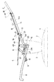
【図1】本発明の実施例の椅子における通常の着座姿勢を示す側面図で、説明上、フレーム部分で示している。
【図2】図1の前面図。
【図3】図1におけるスライド力の調整手段を示す側面図。
【図4】図3におけるK−K線断面図。
【図5】図3及び図4に示す挟持部材を示す図。
【図6】図3に示すL−L線断面図。
【図7】図1におけるM−M線断面図。
【図8】図7におけるN−N線断面図。
【図9】図1の姿勢から背もたれを倒伏した姿勢を示す側面図。
【図10】図9の姿勢からヘッドレストを倒伏した安全休息姿勢を示す側面図。
【符号の説明】
4 肘板
6 吊り部材を回転可能に支持する軸
7 吊り部材
8 座フレーム
14 背フレーム
14b 背フレームの下部
19 挟持部材
21 調整部材
26 体調つまみ
31 調整手段[0001]
BACKGROUND OF THE INVENTION
The present invention relates to a chair, and more particularly to a reclining chair in which a seat moves forward by tilting a backrest backward.
[0002]
[Prior art]
Conventionally, in the reclining chair as described above, as a structure for supporting the seat so as to be movable in the front-rear direction, a rail is provided on the fixed frame of the chair in the front-rear direction, and the seat is slidably mounted on the rail. The method is known.
[0003]
[Problems to be solved by the invention]
In the conventional structure in which the seat is slidably mounted on the rail, the sliding friction resistance is large. The return force when returning to is increased.
[0004]
For this reason, there is a problem that it is difficult to get up from a reclining posture, particularly in a user with weak power such as an elderly person.
[0005]
Therefore, the present invention has an adjustment mechanism that adjusts the moving force of the seat, and when the adjustment mechanism is made free, the movement of the seat in the front-rear direction is reduced compared to the conventional rail system, and particularly the force. The object is to provide a chair that can be easily raised even by elderly people with weakness.
[0006]
[Means for Solving the Problems]
In order to solve the above-mentioned problem, the first invention according to
The pre-Symbol adjusting means, said suspending member, an adjusting member which moves together with該吊Ri member, the fixed member is provided with a clamping member for slidably sandwich the adjusting member, the physical condition knobs provided on the fixed member, the It is configured to adjust the holding force of the adjusting member by the holding member by operating a physical condition knob .
[0007]
In the present invention, it is possible to prevent the seat and the backrest from moving unnecessarily during use by adjusting the resistance against the swinging of the suspension member to an amount suitable for the user by the adjusting means.
[0008]
Further, by eliminating the resistance force by the adjusting means and allowing the suspension member to freely swing, the seat freely swings in a pendulum manner by the suspension member. Thus, by suspending and holding the seat and swinging it in a pendulum manner, the resistance to movement of the seat is reduced as compared with the conventional seat supported by a rail.
[0009]
A second invention of
[0010]
According to a third aspect of the present invention, in the first or second aspect, the adjusting member and the clamping member are formed in a plate shape .
A fourth invention according to
A fifth invention according to
[0011]
DETAILED DESCRIPTION OF THE INVENTION
Embodiments of the present invention will be described based on the examples shown in the drawings.
[0012]
1 and 2,
[0013]
A
[0014]
A
[0015]
A
[0016]
As shown in FIG. 2, the
[0017]
With the above configuration, when the upper frame 14a of the
[0018]
Next, the detail of the structure of each part is demonstrated.
[0019]
An inverted U-shaped body
[0020]
Between the pressing
[0021]
A front portion of the
[0022]
Then, the clamping
[0023]
An
The
[0024]
A
[0025]
With the above structure, when the
[0026]
The
[0027]
Next, the peripheral structure of the
[0028]
7 is an enlarged sectional view taken along line MM in FIG. 1, and FIG. 8 is a sectional view taken along line NN in FIG.
[0029]
In FIG. 7,
[0030]
A
[0031]
In FIG. 1, a
[0032]
The
[0033]
With the above configuration, the locking
[0034]
Next, the
[0035]
In FIG. 7, a
[0036]
A lock
[0037]
The
[0038]
A
[0039]
The
[0040]
With this configuration, when the user manually pushes the
[0041]
In the illustrated embodiment, the
[0042]
The
[0043]
Next, the operation will be described.
[0044]
The state shown in FIG. 1 is a state in which the
[0045]
When the reclining state shown in FIG. 9 is made from this state, the user first sits on the seat formed by the
[0046]
Next, when the user leans against the backrest formed by the upper frame 14 a of the
[0047]
At this time, since the
[0048]
Further, since the rotation of the locking
[0049]
Therefore, as shown in FIG. 9, the backrest is in a reclining state, and the headrest is in an upright state where it is easy to watch TV or read.
[0050]
Next, when the headrest is tilted backward from the state of FIG. 9, the seated user releases the
[0051]
This release operation moves the
[0052]
Next, when the headrest is erected from the state shown in FIG. 10, only the
[0053]
When the
[0054]
When the
[0055]
Therefore, only the headrest can be raised from the state shown in FIG. 10, and the reclining state shown in FIG. 9 in which the standing state of the headrest is locked can be obtained. Further, by raising the backrest from the state shown in FIG. As shown in FIG. 4, the backrest and the headrest can be raised, and the standing state of the headrest can be locked.
[0056]
Further, even if the back frame stands up from a state where it is inclined at an angle between the sitting posture shown in FIG. 1 and the complete resting posture shown in FIG. 10, the headrest tilted in the same manner as described above is raised. The standing state can be locked.
[0057]
【The invention's effect】
As described above, according to the present invention, the movement of the seat in the front-rear direction becomes lighter than that of the conventional rail system by freeing the resistance force by the adjusting means. Therefore, it becomes easy to get up from the reclining posture, particularly in elderly people with weak power.
[0058]
Further, by suspending and holding the seat with the suspension member, the structure can be simplified as compared with the rail system, the product cost can be reduced, and the occurrence of failure can be reduced.
[Brief description of the drawings]
FIG. 1 is a side view showing a normal sitting posture in a chair according to an embodiment of the present invention, which is shown by a frame portion for explanation.
2 is a front view of FIG. 1. FIG.
FIG. 3 is a side view showing a slide force adjusting means in FIG. 1;
4 is a sectional view taken along the line KK in FIG. 3;
5 is a view showing the clamping member shown in FIGS. 3 and 4. FIG.
6 is a cross-sectional view taken along line LL shown in FIG.
7 is a cross-sectional view taken along line MM in FIG.
8 is a cross-sectional view taken along line NN in FIG.
9 is a side view showing a posture in which the backrest is lying down from the posture of FIG. 1. FIG.
10 is a side view showing a safety resting posture with the headrest lying down from the posture of FIG. 9;
[Explanation of symbols]
4 Elbow
Claims (5)
前記調整手段を、前記吊り部材に、該吊り部材とともに移動する調整部材を設け、固定部材に、前記調整部材を摺動可能に挟持する挟持部材を設け、固定部材に体調つまみを設け、該体調つまみの操作により前記挟持部材による前記調整部材の挟持力を調整するように構成したことを特徴とする椅子。A back frame that is provided so as to be rotatable in the front-rear direction of the chair by a support shaft fixed to the rear portion of the chair, and an upper portion is vertically connected to the fixed portion so as to be rotatable by the shaft. A suspension member that swings in the front-rear direction around the upper part, a seat frame that is rotatably connected to the lower part of the suspension member and the lower part of the back frame, and is provided in a substantially horizontal state, and the swinging of the suspension member A chair having adjusting means for adjusting the resistance to
The pre-Symbol adjusting means, said suspending member, an adjusting member which moves together with該吊Ri member, the fixed member is provided with a clamping member for slidably sandwich the adjusting member, the physical condition knobs provided on the fixed member, the A chair configured to adjust a holding force of the adjusting member by the holding member by an operation of a physical condition knob .
Priority Applications (1)
| Application Number | Priority Date | Filing Date | Title |
|---|---|---|---|
| JP2001311077A JP3967902B2 (en) | 2001-10-09 | 2001-10-09 | Chair |
Applications Claiming Priority (1)
| Application Number | Priority Date | Filing Date | Title |
|---|---|---|---|
| JP2001311077A JP3967902B2 (en) | 2001-10-09 | 2001-10-09 | Chair |
Publications (2)
| Publication Number | Publication Date |
|---|---|
| JP2003111636A JP2003111636A (en) | 2003-04-15 |
| JP3967902B2 true JP3967902B2 (en) | 2007-08-29 |
Family
ID=19129962
Family Applications (1)
| Application Number | Title | Priority Date | Filing Date |
|---|---|---|---|
| JP2001311077A Expired - Fee Related JP3967902B2 (en) | 2001-10-09 | 2001-10-09 | Chair |
Country Status (1)
| Country | Link |
|---|---|
| JP (1) | JP3967902B2 (en) |
Cited By (1)
| Publication number | Priority date | Publication date | Assignee | Title |
|---|---|---|---|---|
| EP4403071A1 (en) * | 2023-01-20 | 2024-07-24 | Voijko Franc Dodic | Seating furniture |
Families Citing this family (3)
| Publication number | Priority date | Publication date | Assignee | Title |
|---|---|---|---|---|
| JP2013255553A (en) * | 2012-06-11 | 2013-12-26 | chang-zhen Lin | Angle adjusting device of backrest |
| NO346789B1 (en) * | 2021-01-11 | 2023-01-09 | H2 Norway As | Seating arrangement |
| CN114027655A (en) * | 2021-12-09 | 2022-02-11 | 安吉富和家具有限公司 | Back-leaning self-adaptive high-performance office chair |
-
2001
- 2001-10-09 JP JP2001311077A patent/JP3967902B2/en not_active Expired - Fee Related
Cited By (1)
| Publication number | Priority date | Publication date | Assignee | Title |
|---|---|---|---|---|
| EP4403071A1 (en) * | 2023-01-20 | 2024-07-24 | Voijko Franc Dodic | Seating furniture |
Also Published As
| Publication number | Publication date |
|---|---|
| JP2003111636A (en) | 2003-04-15 |
Similar Documents
| Publication | Publication Date | Title |
|---|---|---|
| JP2505458B2 (en) | Height-adjustable swivel chair with gas pressure spring | |
| JP4141050B2 (en) | Chairs, especially office chairs | |
| US8662591B2 (en) | Reclining chair headrest with height adjustment mechanism | |
| JPS6365810A (en) | Sitting furniture | |
| JP2000139602A (en) | Locking device locking mechanism | |
| JP4160742B2 (en) | Rocking chair | |
| JP4990893B2 (en) | Vehicle seat | |
| JPH067803B2 (en) | Chair | |
| US20060061149A1 (en) | Self-leveling tablet mechanism for a chair | |
| JP3967902B2 (en) | Chair | |
| JP4546769B2 (en) | Chair with table | |
| JP3914020B2 (en) | Chair | |
| JP2797273B2 (en) | Chair with backrest | |
| WO2018196480A1 (en) | Multifunctional balance chair | |
| WO2011091612A1 (en) | Adjusting stand for chairs | |
| JP2002136376A (en) | Device for adjusting back and forth directional position of seat | |
| KR200382313Y1 (en) | angle control apparatus of chair | |
| JP4500388B2 (en) | Chair seat and back tilting device | |
| JPH0325635Y2 (en) | ||
| JPH07246123A (en) | Swinging mechanism for seat plate and back rest of chair | |
| JPH066088B2 (en) | Reclining device | |
| JP2583188Y2 (en) | Chair and backrest tilting device | |
| JP2001057918A (en) | Chair | |
| JPS5929585Y2 (en) | Chair | |
| JPH052122Y2 (en) |
Legal Events
| Date | Code | Title | Description |
|---|---|---|---|
| A621 | Written request for application examination |
Free format text: JAPANESE INTERMEDIATE CODE: A621 Effective date: 20040928 |
|
| A977 | Report on retrieval |
Free format text: JAPANESE INTERMEDIATE CODE: A971007 Effective date: 20061116 |
|
| A131 | Notification of reasons for refusal |
Free format text: JAPANESE INTERMEDIATE CODE: A131 Effective date: 20070109 |
|
| A521 | Written amendment |
Free format text: JAPANESE INTERMEDIATE CODE: A523 Effective date: 20070309 |
|
| TRDD | Decision of grant or rejection written | ||
| A01 | Written decision to grant a patent or to grant a registration (utility model) |
Free format text: JAPANESE INTERMEDIATE CODE: A01 Effective date: 20070515 |
|
| A61 | First payment of annual fees (during grant procedure) |
Free format text: JAPANESE INTERMEDIATE CODE: A61 Effective date: 20070601 |
|
| R150 | Certificate of patent or registration of utility model |
Free format text: JAPANESE INTERMEDIATE CODE: R150 |
|
| FPAY | Renewal fee payment (event date is renewal date of database) |
Free format text: PAYMENT UNTIL: 20130608 Year of fee payment: 6 |
|
| FPAY | Renewal fee payment (event date is renewal date of database) |
Free format text: PAYMENT UNTIL: 20130608 Year of fee payment: 6 |
|
| S533 | Written request for registration of change of name |
Free format text: JAPANESE INTERMEDIATE CODE: R313533 |
|
| FPAY | Renewal fee payment (event date is renewal date of database) |
Free format text: PAYMENT UNTIL: 20130608 Year of fee payment: 6 |
|
| R350 | Written notification of registration of transfer |
Free format text: JAPANESE INTERMEDIATE CODE: R350 |
|
| FPAY | Renewal fee payment (event date is renewal date of database) |
Free format text: PAYMENT UNTIL: 20130608 Year of fee payment: 6 |
|
| FPAY | Renewal fee payment (event date is renewal date of database) |
Free format text: PAYMENT UNTIL: 20160608 Year of fee payment: 9 |
|
| LAPS | Cancellation because of no payment of annual fees |