JP3944824B2 - Data communication apparatus, display method, program, and program storage medium - Google Patents
Data communication apparatus, display method, program, and program storage medium Download PDFInfo
- Publication number
- JP3944824B2 JP3944824B2 JP2001345443A JP2001345443A JP3944824B2 JP 3944824 B2 JP3944824 B2 JP 3944824B2 JP 2001345443 A JP2001345443 A JP 2001345443A JP 2001345443 A JP2001345443 A JP 2001345443A JP 3944824 B2 JP3944824 B2 JP 3944824B2
- Authority
- JP
- Japan
- Prior art keywords
- communication
- target device
- icon
- communication target
- data
- Prior art date
- Legal status (The legal status is an assumption and is not a legal conclusion. Google has not performed a legal analysis and makes no representation as to the accuracy of the status listed.)
- Expired - Fee Related
Links
Images


Landscapes
- Mobile Radio Communication Systems (AREA)
Description
【0001】
【発明の属する技術分野】
本発明は、データ通信装置に関し、ブルートゥース(Bluetooth:登録商標)に準拠した複数の通信装置によって構築されるデータ通信システムに適用して好適なものである。
【0002】
【従来の技術】
近年、標準化団体のBluetooth SIG(Special Interest Group) により標準化された近距離無線データ通信規格であるブルートゥースに準拠した通信装置が開発されている。
【0003】
ブルートゥースは、2.4[GHz]帯のISM(Industrial Scientific Medical)帯に周波数幅 1[MHz] の通信周波数を、時分割多重の時間単位(以下、これを時間スロットと呼ぶ)である 625 [μsec]毎に 79[MHz]の周波数幅の範囲内でランダムに変化(ホッピング)させる周波数ホッピング型のスペクトラム拡散通信方式を用い、およそ 10[m]四方の空間内にデータ伝送を行うよう規定されている。
【0004】
従って、かかる通信装置を複数用いて構築されるデータ通信システムは、複数の通信装置同士における周波数ホッピングのパターンと、時間スロットとを共有して周波数軸上及び時間軸上で同期を確立した状態(以下、これをピコネット(piconet) と呼ぶ)を形成する。
【0005】
このときピコネットには、図18に示すように、複数の通信装置のうち、データ通信システムの構築元となって制御機能を担う1つの通信装置(以下、これをマスタ(master)と呼ぶ)が必ず存在し、当該マスタにより制御される1又は2以上の通信装置(以下、これをスレーブ(slave) と呼ぶ)が存在する。
【0006】
この場合マスタは、1又は2以上のスレーブを制御することにより、当該スレーブに対して自らの周波数ホッピングのパターン及び時間スロットに同期させる。従ってマスタは、1又は2以上のスレーブと個別に各種データの授受(データ通信)を行い得るようになされている。
【0007】
因みにピコネットは、他のピコネットと相互接続することによりスカッタネット(scatternet)と呼ばれるネットワークシステムをも構築し得るようになされている。
【0008】
このようにデータ通信システムは、単に1対1の通信装置間におけるケーブルの代替えによるデータ通信のみならず、基地局等に相当する中継装置を設けることなく、1対複数の通信装置間におけるデータ通信を簡易に行い得るようになされている。
【0009】
【発明が解決しようとする課題】
ところで、例えば具体的に図19に示すデータ通信システム1において、PDA(Personal Digital Assistants) 2(マスタ)は、当該PDA2に対しておよそ10[m] 四方の空間AR内に存在する携帯電話機3、4、5及び6(スレーブ)とピコネットを形成した後、当該携帯電話機3、4、5及び6における属性情報を要求するようになされている。
【0010】
この場合、PDA2は、携帯電話機3、4、5及び6から供給される各々の属性情報に基づいて例えば図20に示すように、当該携帯電話機3、4、5及び6の名称を表すデバイス名8A、8B、8C及び8Dと、各種電子機器のうち携帯電話機であることを表すデバイスアイコン7A、7B、7C及び7Dとでなるデバイス選択画面10を表示部(図示せず)に表示する。
【0011】
ここで、PDA2は、内部のハードディスク(図示せず)に格納されている任意のデータを携帯電話機3、4、5又は6に送信する場合、まず、任意のデバイスアイコン7A〜7D(デバイス名8A〜8D)を使用者にクリック操作させて例えば使用者希望の送信対象の携帯電話機3に対応するデバイスアイコン7Aを選択させる。
【0012】
次に、PDA2は、例えば図21に示すような送信データ選択画面11を表示し、フォルダを選択させる選択バー12をクリック操作させて選択させた後、当該フォルダ内のデータ群を一覧する一覧画面13をクリック操作させて任意のデータを使用者に選択させる。
【0013】
さらに、PDA2は、送信データ選択画面11の送信ボタン14を使用者にクリック操作させることにより、当該使用者によって選定された任意のデータを携帯電話機3へ送信するようになされている。
【0014】
しかしながら、PDA2は、携帯電話機3、4、5又は6に任意のデータを送信する度に、上述した一連の操作を使用者に繰り返し行わせなければならず、操作性が悪いという問題があった。
【0015】
本発明は以上の点を考慮してなされたもので、操作性を向上し得るデータ通信装置、表示方法、プログラム及びプログラム格納媒体に適用して好適なものである。
【0016】
【課題を解決するための手段】
かかる課題を解決するため本発明は、通信対象装置と近距離無線通信路を介してネットワークを形成する場合に、通信対象装置に対して近距離無線通信路を介して所定の信号を送信すべきことを要求し、通信対象装置から送信された信号を受信し、受信した信号に基づいて、前期データ通信装置における基準位置に対する通信対象装置の相対的な方角を特定し、方角特定手段により特定された方角に対応する表示画面位置に、通信対象装置を表すアイコンを表示するようにした。
【0017】
【発明の実施の形態】
以下図面について、本発明の一実施の形態を詳述する。
【0018】
(1)全体構成
図1において、20は全体として本発明によるデータ通信システムを示し、ブルートゥースに準拠したブルートゥースモジュールを内蔵するPDA(PersonalDigital Assistants) 21、22、23、24及び25によって例えばパーティ会場で構築されている。
【0019】
このパーティ会場において、PDA21は、データ通信システム20の構築元であるマスタとして機能しており、当該PDA21に対して数[m] 四方の所定範囲AR1に内に存在する通信対象のPDA22、23、24及び25をスレーブとして機能させてピコネットを形成している。
【0020】
ピコネットとは、ブルートゥース(Bluetooth:登録商標)規格における周波数幅 1[MHz] の通信周波数を 79[MHz]の周波数幅の範囲内でランダムに変化(ホッピング)させる周波数ホッピングパターンと、時分割多重の時間単位(以下、これを時間スロットと呼ぶ)とを複数の通信装置同士が共有している状態(すなわち周波数軸上と時間軸上とで同期を確立した状態)をいう。
【0021】
従って、マスタとして機能するPDA21は、スレーブとして機能するPDA22、23、24及び25に対して自らの周波数ホッピングのパターン及び時間スロットに同期させており、これにより当該PDA22、23、24及び25とそれぞれ個別に各種データの授受(データ通信)を行い得るようになされている。
【0022】
またPDA22、23、24又は25(スレーブ)は、PDA21(マスタ)を介して他のスレーブ(PDA22、23、24又は25)とも各種データの授受(データ通信)を行い得るようになされている。
【0023】
(2−1)PDAの外観構成
次に、PDA21〜25の外観構成について述べるが、当該PDA21〜25の外観構成はそれぞれ同一の構成であることにより、ここではPDA21のみの外観構成について述べる。
【0024】
図2に示すように、PDA21は筐体ケース30を有し、当該筐体ケース30の正面30Aには、例えば液晶ディスプレイでなる表示部31が設けられている。
【0025】
また筐体ケース30の正面30Aにおける下端部近傍には、年月日毎のスケジューラ画面を表示部31に表示させる年月日スケジューラボタン32A、時間毎のスケジューラ画面を表示させる時間スケジューラボタン32B、メモ帳画面を表示させるメモ帳ボタン32C、住所録画面を表示させる住所録ボタン32D、所定の選択項目等をスクロールさせるためのスクロールボタン32E、及びPDA21に主電源を投入させるための電源ボタン32Fでなる操作部32が設けられている。
【0026】
また筐体ケース30の左側面30Bにおける上端部近傍には、押下操作及び回転操作自在な回転操作子(以下、これをジョグダイヤルと呼ぶ)33が設けられている。ジョグダイヤル33は回転操作されると、所定の選択項目等をスクロールするスクロール命令を入力し、また押下操作されると、所定の選択項目等を決定する決定命令を入力し得るようになされている。
【0027】
また筐体ケース30の上面30Cにおけるほぼ中央部には、着脱自在な図示しないメモリスティック(ソニー株式会社、商標)を装着するためのメモリスティックスロット34が設けられており、ジョグダイヤル33等による所定の操作に応じて各種データを当該メモリスティックに書き込みや読み出し可能になされている。
【0028】
因みに、メモリスティックは、小型かつ薄型形状のプラスチックケース内に、電気的に書き換え可能な不揮発性メモリの一種であるフラッシュメモリ素子が収納されており、プラスチックケースに設けられた外部端子を介して内部のフラッシュメモリ素子に各種データを記録再生可能になされている。
【0029】
これによりメモリスティックスロット34を有するPDA21は、メモリスティックスロットを有する他の種々の電子機器とメモリスティックを介して各種データの共有化を図り得るようになされている。
【0030】
さらに表示部31の下側には、透明な感圧フィルムでなるタッチパッド35が設けられ、当該タッチパッド35には、メインメニュー(選択項目)画面を表示部31に表示させるホームキー35A、サブメニュー画面を表示させるメニューキー35B、検索画面を表示させる検索キー35C、文字入力画面を表示させるキーボードキー35D、文字等の入力や所定の操作を行うための仮想パッド35及び、当該文字に対する各種操作を行う各種文字操作キー35Fが設けられている。
【0031】
この仮想パッド35Eは、通常モード時、スライラスと呼ばれる専用ペンにより押圧されると、表示部31に表示される所定画面上における例えばアイコンを選択する選択命令を入力し得ると共に、当該専用ペンにより表面をなぞられると、表示部31に表示される所定画面上にあたかも文字や線等を書き込む書込命令を入力し得るようになされている。
【0032】
かかる構成に加えて、筐体ケース30の正面30Aにおける下端部には、PDA21に対しておよそ数[m] 四方の空間内に存在する通信対象装置とピコネットを形成させてデータ通信を行わせるためのネットワークボタン36が設けられている。
【0033】
このネットワークボタン36が押下された場合、表示部31には、仮想パッド35Eの操作に追従して表示画面上を移動するカーソルが表示されるようになされており、このとき仮想パッド35Eは、通常モードから操作入力モードに移行し、専用ペンに応動して表示画面上のカーソルを移動させる移動命令を入力し得るようになされている。
【0034】
また仮想パッド35Eは、操作入力モードにおいて、専用ペンを任意の位置で押圧された状態のまま所定期間維持(以下、これをクリック操作と呼ぶ)されると、所定画面上における例えばアイコンを選択する選択命令を入力し得るようになされている。
【0035】
さらに仮想パッド35Eは、操作入力モードにおいて、専用ペンをクリック操作された後に当該仮想パッド35Eから離すことなくなぞられる(以下、これをドラッグ操作と呼ぶ)と、選択されたアイコン等を移動するドラッグ命令を入力し得るようになされている。
【0036】
これに加えて仮想パッド35Eは、操作入力モードにおいて、専用ペンをドラッグ操作された後に所定の位置で離される、又は専用ペンをクリック操作された後に当該クリック操作された位置で再び離される(以下これをドロップ操作と呼ぶ)と、選択されたアイコン等を解除するドロップ命令を入力し得るようになされている。
【0037】
また、図2との対応部分に同一符号を付した図3及び図4に示すように、筐体ケース30の背面30Dにおける上端段差部30Eには、当該背面30Dの中心点31Aを中心にメモリスティックソロット34方向へ弧状に所定間隔で赤外線送受信部37A〜37Oがそれぞれ設けられている。
【0038】
この赤外線送受信部37A〜37Oは、送信部(図示せず)を介して赤外線送信信号を外部に送信すると共に、当該外部から供給される赤外線受信信号を受信部(図示せず)を介して入力し得るようになされている。
【0039】
(2−2)PDAの回路構成
次に、PDA21〜25の回路構成について述べるが、当該PDA21〜25の回路構成はそれぞれ同一の構成であることにより、ここではPDA21のみの回路構成について述べる。
【0040】
図5に示すように、PDA21は、当該PDA21における各種機能を統括的に制御するCPU(Central Processing Unit) 40に対して、フラッシュROM(Read On Memory)41、DRAM(Dynamic Random Access Memory)42、システムコントローラ43、ブルートゥースに準拠したブルートゥースモジュール44、メモリスティックインターフェイス45、表示制御部46、入出力インターフェイス47、赤外線インターフェイス48がそれぞれバスBUSを介して接続されており、当該バスを介して各回路部間における各種データの授受を行うようになされている。
【0041】
またシステムコントローラ43には、操作部32、ジョグダイヤル33、タッチパッド35及びネットワークボタン36(図2)が接続され、メモリスティックインターフェイス45には、メモリスティックスロット34が接続され、入力インターフェイス47には、パーソナルコンピュータ等のとの間で所定のケーブルを介してデータ通信するためのI/O(Input Output)コネクタ49が接続され、赤外線インターフェイス48には、赤外線送受光部37A〜37O(図3)がパラレル接続されており、各回路部間における各種データの授受を行い得るようになされている。
【0042】
さらに、フラッシュROM41には、オペレーティングシステムを実現する基本プログラムや、ピコネットを形成して各種データの授受を行わせるデータ通信プログラム等の各種アプリケーションプログラムと、例えば図6に示すようなPDA21の使用者自身に関する顔写真、氏名や住所等を示したカード状の画面dis1の情報(以下、これを個人カードデータと呼ぶ)や、各種設定情報等の個人用データとが格納されている。
【0043】
従ってCPU40は、操作部32、ジョグダイヤル33、タッチパッド35又はネットワークボタン36の操作に応じてフラッシュROM41に予め格納している各種プログラムを適宜読み出してDRAM42に展開することにより、当該プログラムに従った処理を実行し得るようになされていると共に、当該処理内容を必要に応じて表示制御部46を介して表示部31に表示するようになされている。
【0044】
例えば、CPU40は、メモリスティック(図示せず)をメモリスティックスロット34に挿着した状態において、ジョグダイヤル33又はタッチパッド35から所定の記録操作が行われると、当該メモリスティック内に収納されたフラッシュメモリ素子に書き込まれているデータをメモリスティックインターフェイス45を介して読み出し、これをフラッシュROM41に格納(記録)する。
【0045】
またCPU40は、ジョグダイヤル33又はタッチパッド35から個人カードデータを読み出す所定の読出操作が行われると、フラッシュROM41に格納されている個人カードデータを読み出し、これを表示制御部46を介して図6について上述した個人カード画面dis1を表示部31に表示する。
【0046】
ところで、CPU40は、ネットワークボタン36が押下されると、フラッシュROM41に格納しているデータ通信プログラムを読み出してDRAM42に展開し、当該データ転送プログラムに従ってブルートゥースモジュール44を制御する。
【0047】
かかるブルートゥースモジュール44には、ブルートゥースクロック(図示せず)、フラッッシュメモリ(図示せず)及びROM(図示せず)が内蔵されており、当該ROMにはブルートゥースアドレスが格納されている。
【0048】
ブルートゥースアドレスとは、ブルートゥースモジュール固有の情報であり、当該ブルートゥースモジュールにおける周波数ホッピングパターンを生成するためのパラメータ等に用いられる識別子である。
【0049】
すなわちブルートゥースモジュール44は、CPU40の制御によりピコネット形成対象に時間軸を確立させるためのブルートゥースクロックのカウンタ情報と、周波数軸を確立させるためのブルートゥースアドレスとを含むピコネット形成要求データをPDA22〜25(図1)に送信して自らの周波数ホッピングパターン及び時間スロットに同期させてピコネットを形成する。
【0050】
その際、ブルートゥースモジュール44は、PDA22、23、24及び25から当該PDA22〜25に内蔵されたブルートゥースモジュール固有のブルートゥースアドレス及び、PDA22〜25の種別(冷蔵庫、携帯電話機又はテレビジョン受像機等)を表す種別データをそれぞれ取得することにより、PDA22、23、24及び25を特定するようにようになされている。
【0051】
この状態において、CPU40はシステムコントローラ43を制御することにより、当該システムコントローラ43を介して当該タッチパッド35の仮想パッド35Eを通常モードから操作入力モードに移行させる。
【0052】
一方、CPU40は、赤外線インターフェイス48を介して赤外線送受信部37A〜37Oを制御する。そしてCPU40は、ピコネットを形成する際に取得したPDA22固有のブルートゥースアドレスに基づいてPDA22の存在する方角を検知するための検知用信号を要求する検知用信号要求データを生成し、これを赤外線インターフェイス48及び赤外線送受信部37A〜37Oを順次介して検知用信号要求信号として送信する。
【0053】
この場合CPU40は、図1及び図2との対応部分に同一符号を付した図7に示すように、検知用信号要求信号の応答結果としてPDA22から送信された検知用信号を赤外線送受信部37A〜37Oより入力し、当該各々の検知用信号の受信レベルのうち最も高い受信レベルである例えば赤外線送受信部37Kを特定することにより、中心点31Aに対してPDA22の存在するおおよその方角Dr1を検知する。
【0054】
その後CPU40は、PDA22と同様に、順次PDA23、24、25について、検知用信号の受信レベルが最も高い例えば赤外線送受信部37L、37N、37Dをそれぞれ特定することにより、中心点31Aに対してPDA23、24、25の存在するおおよその方角Dr2、Dr3、Dr4を検知する。
【0055】
この実施の形態の場合、フラッシュROM41には、赤外線送受信部37A〜37Oから入力する入力信号の電圧レベルに応じた中心点31Aからの距離が予め距離設定情報として格納されている。
【0056】
従って、CPU40は、PDA22〜25における方角Dr1〜Dr4のみならず、当該PDA21からPDA22〜25のまでの距離までをも特定し得るようになされている。
【0057】
そしてCPU40は、図6について上述した個人カード画面dis1が表示部31に表示されている際にネットワークボタン36が押下されている場合、例えば図8に示すように、PDA22の方角Dr1に対応づけたデバイス特定領域dis3と、PDA22の方角Dr2及びDr3に対応づけたデバイス特定領域dis4と、PDA22の方角Dr1に対応づけたデバイス特定領域dis2とを表示部31の周端に表示する。
【0058】
その際、CPU40は、PDA22〜25からそれぞれ取得した種別データに基づくデバイスアイコン22A、23A、24A、25Aと、距離設定情報及び赤外線送受信部37K、37L、37N、37Dに基づいて算出された中心点31AからPDA22〜25までの距離22B、23B、24B、25BとをPDA22〜25の方角Dr1〜Dr4に対応させてデバイス特定領域dis2〜dis4に表示する。
【0059】
これによりCPU40は、カーソルCLの移動し得る表示部31における周端のデバイス特定領域dis2〜dis4内に、ピコネットを形成したPDA22〜25を対応付けるのみならず、その距離及び種別をも使用者に視覚的に把握させ得るようになさている。
【0060】
このときCPU40は、仮想パッド35Eによりクリック操作、ドラッグ操作及びドロップ操作されると、当該操作により仮想パッド35Eから入力される各種命令に応じてカーソルCLを介して個人カード画面dis1を表示部31上で移動させ得るようになされている。
【0061】
ここで、CPU40は、例えば図9に示すように、仮想パッド35Eにより例えば個人カード画面dis1上にカーソルCLが位置している状態でクリック操作されると、そのカーソルCLの位置を移動開始位置X1として検出する。
【0062】
さらにCPU40は、クリック操作されたまま例えばデバイス特定領域dis3上までドラッグ操作された後にドロップ操作されると、当該ドロップ操作された際のカーソルCLの位置を移動終了位置X2として検出する。
【0063】
この場合CPU40は、PDA22の方角Dr1に対応づけたデバイス特定領域dis3内に移動終了位置X2(すなわちカーソルCL)が含まれていることにより、個人カード画面dis1の移動が当該PDA22の存在する方角側であると判定する。
【0064】
そしてCPU40は、フラッシュROM41に格納されている個人カードデータを読み出し、これをデバイス特定領域dis3に対応付けた方角Dr1に存在するPDA22にブルートゥースモジュール44を介して送信する。
【0065】
これに加えて、CPU40は移動終了位置X2を検出したとき、デバイス特定領域dis3上へ移動させた個人カード画面dis1を元の位置に戻して表示する(図8)ことにより、当該個人カード画面dis1に基づく個人カードデータを再度送信する場合でも、ドラッグ操作及びドロップ操作のみで容易に使用者所望のPDA22〜25に送信し得るようになされている。
【0066】
また、CPU40は、例えば個人カード画面dis1が複数のデバイスアイコン23A及び25Aを有するデバイス特定領域dis4上までドラッグ操作された後にドロップ操作されると、図10に示すような通信装置選択画面dis5を表示部31に表示して使用者に送信希望のPDA23又は25を選択させることにより、当該使用者の所望とする通信装置へ確実にデータを送信し得るようになされている。
【0067】
これに対して、CPU40は、通常のメニュー画面(例えばメインメニュー画面等)が表示部31に表示されている際にネットワークボタン36が押下された場合、例えば図8との対応部分に同一符号を付して示す図11のように、PDA22〜25の方角Dr1〜Dr4に基づいてデバイス特定領域dis2〜dis4と、フラッシュROM41に格納されている各種個人データを表示するデータ表示画面dis6とを表示部31に表示する。
【0068】
その際、CPU40は、デバイスアイコン22A、23A、24A、25Aと、距離22B、23B、24B、25BとをPDA22〜25の方角Dr1〜Dr4に対応させてデバイス特定領域dis2〜dis4に表示すると共に、各種個人データの階層構造に応じてファイルアイコンD1又はフォルダアイコンD2としてデータ表示画面dis6内に表示する。
【0069】
ここで、CPU40は、図8及び図9について上述した場合と同様に、仮想パッド35Eにより例えばフォルダアイコンD2を移動開始位置X1からデバイス特定領域dis2上までドラッグ操作された後にドロップ操作されると、当該個人カード画面dis1のドロップ位置を移動終了位置X3として検出する。
【0070】
この場合CPU40は、PDA24の方角Dr4に対応づけたデバイス特定領域dis2内に個人カード画面dis1の移動終了位置X3が含まれていることにより、フォルダアイコンD2の移動が当該PDA24の存在する方角側であると判定する。
【0071】
そしてCPU40は、フォルダアイコンD2に対応するデータをフラッシュROM41から読み出してPDA22、23、24又は25にブルートゥースモジュール44を介して送信し得るようになされている。
【0072】
また、CPU40は移動終了位置X3を検出したとき、デバイス特定領域dis2上へ移動させたフォルダアイコンを元の位置に戻して表示することにより、当該フォルダアイコンに基づく各種データを再度送信する場合でも、ドラッグ及びドロップ操作のみで容易に使用者所望の通信対象装置に送信し得るようになされている。
【0073】
このようにCPU40は、実際のPDA22〜25との対応関係を使用者に視覚的に把握させるのみならず、所望のデータに対してドラッグ操作及びドロップ操作するだけで実際のPDA22〜25に送信し得るデバイス特定領域dis2〜dis4を表示し得るようになされている。
【0074】
因みに、CPU40は、PDA22、23、24又は25から検知用信号要求信号を赤外線送受信部37A〜37Oを介して受信した場合には、当該検知用信号要求信号に基づいて検知用信号を生成し、これを赤外線送受信部37A〜37Oを介してPDA22、23、24又は25に送信するようになされている。
【0075】
(3−1)データ通信処理手順
かかるPDA21における一連のデータ通信処理をまとめてみると、図12に示すように、CPU40は、ルーチンRT1の開始ステップからステップSP1に移って、PDA22、23、24及び25とピコネットを形成し、続くステッステップSP2に移る。
【0076】
ステップSP2においてCPU40は、タッチパッド35の仮想パッド35Eを通常モードから操作入力モードに移行させ、続くステップSP3に移る。
【0077】
ステップSP3においてCPU40は、ピコネットを形成する際に取得したPDA22(PDA23、24又は25)固有のブルートゥースアドレスに基づいて検知用信号要求データを生成し、これを赤外線インターフェイス48及び赤外線送受信部37A〜37Kを順次介して検知用信号要求信号として送信し、続くステップSP4に移る。
【0078】
ステップSP4においてCPU40は、検知用信号要求信号の応答結果であるの検知用信号を赤外線送受信部37A〜37Kを介して受信したか否かを判断する。
【0079】
ここで否定結果が得られると、CPU40は検知用信号を受信するまで待ち受ける。これに対して肯定結果が得られると、CPU40は、続くステップSP5に移る。
【0080】
ステップSP5においてCPU40は、背面30Dの中心点31Aに対して例えばPDA22(PDA23、24又は25)の存在するおおよその方角Dr1(方角Dr2、Dr3又はDr4)を検知し、続くステップSP6に移る。
【0081】
ステップSP6においてCPU40は、ピコネットを形成したPDA22、23、24及び25の存在するおおよその方角Dr1、方角Dr2、Dr3及びDr4を全て検知したか否かを判断する。
【0082】
ここで否定結果が得られると、CPU40はステップSP2に戻る。すなわちCPU40はステップSP5において肯定結果が得られるまで、ピコネットを形成したPDA22、23、24又は25の存在するおおよその方角Dr1、方角Dr2、Dr3又はDr4を順次検知する。これに対して肯定結果が得られると、CPU40は、続くステップSP7に移る。
【0083】
ステップSP7においてCPU40は、デバイス特定領域dis2〜dis4と、必要に応じてデータ表示画面dis6とを表示部31に表示し、続くサブルーチンSRT1に移る。
【0084】
サブルーチンSRT1においてCPU40は、データ転送処理を実行することにより、仮想パッド35Eにより個人カード画面dis1、ファイルアイコンD1又はフォルダアイコンD2がデバイス特定領域dis2、dis3又はdis4上でドロップ操作された場合には、当該個人カード画面dis1に基づく個人カードデータや、ファイルアイコンD1又はフォルダアイコンD2に基づく各種データをデバイス特定領域dis2〜dis4に対応するPDA22〜25に送信し、続くステップSP8に移る。
【0085】
ステップSP8においてCPU40は、ネットワーク解除命令を受けたか否かを判断する。ここで否定結果が得られると、このことはジョグダイヤル33又はタッチパッド35より所定のネットワーク解除操作が行われていないことを表しており、このときCPU40は、サブルーチンSRT1に戻って、再びデータ転送処理を実行する。
【0086】
これに対して肯定結果が得られると、このことはジョグダイヤル33又はタッチパッド35より所定のネットワーク解除操作が行われたことを表しており、このときCPU40は、続くステップSP9に移る。
【0087】
ステップSP9においてCPU40は、タッチパッド35の仮想パッド35Eを通常モードから操作入力モードに移行させ、続くステップSP10に移って、データ通信処理を終了する。
【0088】
(3−2)データ転送処理手順
次に、かかるPDA21のデータ通信処理におけるデータ転送処理を述べる。
【0089】
すなわち図13に示すように、CPU40は、サブルーチンSRT1の開始ステップからステップSP11に移って、ドラッグ命令を検出したか否かを判断する。ここで否定結果が得られると、続くステップSP8に移る。
【0090】
これに対して肯定結果が得られると、このことは仮想パッド35Eにより例えば個人カード画面dis1がドラッグ操作されたことを表しており、このときCPU40は、続くステップSP12に移る。
【0091】
ステップSP12においてCPU40は、ドロップ命令を検出したか否かを判断する。ここで否定結果が得られると、このことは未だ個人カード画面dis1がドラッグ操作され続けていることを表しており、このときCPU40は、ドロップ命令を検出するまで待ち受ける。
【0092】
これに対して肯定結果が得られると、このことは個人カード画面dis1がドラッグ操作された後にドロップ操作されたことを表しており、このときCPU40は続くステップSP13に移る。
【0093】
ステップSP13においてCPU40は、個人カード画面dis1の移動終了位置X2を検出し、続くステップSP14に移る。
【0094】
ステップSP14においてCPU40は、個人カード画面dis1の移動終了位置X2がデバイス特定領域dis2〜dis4範囲内にあるか否かを判断する。ここで否定結果が得られると、CPU40は続くステップSP18に移る。これに対して肯定結果が得られると、CPU40は続くステップSP15に移る。
【0095】
ステップSP15においてCPU40は、移動終了位置X2を含むデバイス特定領域dis2、dis3又はdis4に複数のデバイスアイコン22A、23A、24A又は25Aが表示されているか否かを判断する。
【0096】
ここで否定結果が得られると、このことはデバイス特定領域dis2又はdis3にデバイスアイコン22A、24Aが2以上存在していないことを表しており、このときCPU40は、PDA22、24の方角側への移動であると判定することによりPDA22、24への転送命令であると判断し、続くステップSP17に移る。
【0097】
これに対して肯定結果が得られると、このことはデバイス特定領域dis4にデバイスアイコン23A及び25Aが2以上存在していることを表しており、このときCPU40はPDA23又は25の方角側への移動であると判定し、続くステップSP16に移る。
【0098】
ステップSP16においてCPU40は、図10に示したような通信対象装置選択画面dis5を表示部31に表示して使用者に送信希望のPDA23又は25を選択させ、当該選択されたPDA23又は25への転送命令であると判断し、続くステップSP17に移る。
【0099】
ステップSP17においてCPU40は、ステップSP14又はステップSP15で転送命令であると判断したPDA22、23、24又は25に個人カード画面dis1に基づく個人カードデータを送信し、続くステップSP18に移る。
【0100】
ステップSP18においてCPU40は、ドラッグ操作により移動された個人カード画面dis1を表示部31上の元の位置へ戻し、続くステップSP8に移る。
【0101】
このようにCPU40は、各種データをPDA22〜25に送信する際、使用者に各種設定操作させることなく、使用者所望のデータをドラッグ操作させて当該デバイス特定領域dis2〜dis4にドロップ操作させるだけで、それぞれ対応する実際のPDA22〜25に送信し得るようになされている。
【0102】
(4)動作・効果
以上の構成において、およそ数[m] 範囲内のPDA22〜25とブルートゥースを介して通信路を確立しているPDA21のCPU40は、カーソルCLの移動角度範囲である表示部31の終周端内に、ピコネットを形成したPDA22〜25の存在する方角Dr1〜Dr4を対応付けることにより、デバイス特定領域dis2〜dis4を表示する。
【0103】
そしてCPU40は、カーソルCLにおける移動終了位置X2、X3を検出し、当該移動終了位置X2、X3がデバイス特定領域dis2〜dis4範囲内ある場合には、そのデバイス特定領域dis2〜dis4に対応するPDA22〜25に送信するものと判断し、そのときドロップ操作された個人カード画面dis1、ファイルアイコンD1又はフォルダアイコンD2を送信するようにした。
【0104】
従って、CPU40は、個人カード画面dis1、ファイルアイコンD1又はフォルダアイコンD2に対するドラッグ操作及びドロップ操作をPDA21の使用者に行なわせるのみで、当該ドロップ操作された個人カード画面dis1、ファイルアイコンD1又はフォルダアイコンD2をPDA22、23、24、25に送信することができる。
【0105】
また、CPU40は、赤外線送受信部37A〜37Oを制御して中心点31Aに対してPDA22〜25の存在する方角Dr1〜Dr4を検知することにより、当該カーソルCLの移動角度範囲内である表示部31の周端にデバイス特定領域dis2〜dis4を表示するようにした。
【0106】
従って、CPU40は、所定の設定操作によって移動角度範囲とPDA22〜25とを予め対応付けて記憶しておく必要がないことにより、いずれの場所でピコネットを構築した場合においても、そのときピコネットを構築した通信装置の存在する方角Dr1〜Dr4に対応づけたデバイス特定領域dis2〜dis4を表示することができる。
【0107】
以上の構成によれば、PDA22〜25の存在する方角Dr1〜Dr4に対応づけたデバイス特定領域dis2〜dis4範囲内に個人カード画面dis1等が移動されたとき、そのとき移動されたデバイス特定領域に対応するPDAに個人カード画面dis1等を送信するようにしたことにより、当該個人カード画面dis1等に対するドラッグ操作及びドロップ操作をPDA21の使用者に行なわせるのみで送信することができ、かくして、操作性を向上することができる。
【0108】
(5)他の実施の形態
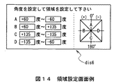
上述の実施の形態においては、対応付手段としてのCPU37によりPDA22〜25に存在する方角に対応付けたデバイス特定領域dis2〜dis4を表示部31に表示したが、例えば図14に示すような角度・領域設定画面dis6により方角に対応付けたデバイス特定領域を予め移動角度範囲として設定する等、要はカーソルCLの移動角度範囲内にPDA22〜25を対応付けていれば良く、また当該領域の表示の有無は問わない。
【0109】
また上述の実施の形態においては、移動検知手段としてのCPU40により移動対象物としての個人カード画面dis1、ファイルアイコンD1又はフォルダアイコンD2の移動をカーソルCLを介して検出する場合について述べたが、本発明はこれに限らず、例えば指、専用ペン(スライラス)、マウス又はジョグダイヤル等、この他種々の移動対象物の移動を検出するようにしても良い。
【0110】
実際上、専用ペン、マウス又はジョグダイヤルを移動対象物として適用する場合、移動検出手段としてのCPU40は、当該専用ペン、マウス、ジョグダイヤル等の操作に応じて入力されるドラッグ命令やドロップ命令によりに移動終了位置を検出する。
【0111】
また指を移動対象物として適用する場合、移動検出手段としてのCPU40は、タッチパッドや表示画面に対して指を介してドラッグ操作及びドロップ操作された際に、その操作に応じてドラッグ命令及びドロップ命令を入力し得るようにすることにより移動終了位置を検出する。
【0112】
さらに上述の実施の形態においては、移動判定手段としてのCPU40により例えばフォルダアイコンD2の移動終了位置X3がPDA22〜25の存在する方角Dr1〜Dr4に対応づけたデバイス特定領域dis2〜dis4範囲内であるかを判定する場合について述べたが、本発明はこれに限らず、例えば図11との対応部分に同一符号を付して示す図15のように、移動開始位置X1から移動終了位置X3を渡る延長線LNがデバイス特定領域dis2〜dis4範囲内であるかを判定するようにしても良い。
【0113】
この場合CPU40は、図13との対応部分に同一符号を付して示す図16のように、ステップSP13(図13)に代わるステップSP21において個人カード画面dis1の移動開始位置X1と移動終了位置X2とを検出し、ステップSP14(図13)に代わるステップSP22において移動開始位置X1から移動終了位置X3を渡る延長線LNがデバイス特定領域dis2〜dis4範囲内であるかを判定し、ステップSP15及びSP16(図13)を除くようにすれば良い。
【0114】
さらに上述の実施の形態においては、移動判定手段としてのCPU40により例えばフォルダアイコンD2の移動終了位置X3がPDA22〜25の存在する方角Dr1〜Dr4に対応づけたデバイス特定領域dis2〜dis4範囲内であるかによって判定する場合について述べたが、本発明はこれに限らず、中心点31Aに対してPDA22、23、24又は25の存在するおおよその方角Dr1、Dr2、Dr3又はDr4を基準とし、移動開始位置X1及び移動終了位置X3とに基づいて算出した移動角度が当該基準に対して所定角度範囲内であるかによって判定するようにしても良い。
【0115】
この場合CPU40は、図16との対応部分に同一符号を付して示す図17のように、ステップSP21(図16)に続いて新たに加えたステップSP32において移動開始位置X1と移動終了位置X3とに基づいて移動角度を算出し、ステップSP22(図16)に代わるステップSP33においてPDA22、23、24又は25の存在するおおよその方角Dr1、Dr2、Dr3又はDr4を基準とし、その基準に対して当該移動角度が所定角度範囲内であるかによって判定するようにすれば良い。
【0116】
さらに上述の実施の形態においては、移動判定手段としてのCPU40により例えばフォルダアイコンD2の移動終了位置X3がPDA22〜25の存在する方角Dr1〜Dr4に対応づけたデバイス特定領域dis2〜dis4範囲内であるかによって判定する場合について述べたが、本発明はこれに限らず、移動開始位置X1から移動終了位置X3までの移動時間が所定時間以下、又は移動開始位置X1から移動終了位置X3までの移動距離が所定距離以上であるかによって判定するようにしても良く、またこれらの組み合わせを満たすかを判定するようにしても良い。
【0117】
さらに上述の実施の形態においては、方角検知手段としての赤外線送受信部37A〜37Oを適用する場合について述べたが、本発明はこれに限らず、例えばアダプティブアレイアンテナ等、この他種々の方角検知手段を適用するようにしても良い。
【0118】
因みに、かかるアダプティブアレイアンテナは、ピコネットを形成するPDA22〜25のブルートゥースモジュールから送信される各種データの指向性に基づいて、任意の基準点としての中心点31Aに対してPDA22〜25の存在する方角を検知する。
【0119】
さらに上述の実施の形態においては、方角検知手段としての赤外線送受信部37A〜37Oを筐体ケース30の背面30Dへ弧状に設ける場合について述べたが、本発明はこれに限らず、例えば筐体ケース30の正面30Aや側面の周囲に設ける等、要は任意の基準点に対して通信対象装置(PDA22〜25)の存在する方角を検知することができれば、この他種々の位置に種々の形状で設けるようにしても良い。
【0120】
さらに上述の実施の形態においては、方角検知手段としての赤外線送受信部37A〜37Oを固定する場合について述べたが、本発明はこれに限らず、回転自在に設けるようにしても良い。この場合、少なくとも1つの赤外線送受信部があれば、任意の基準点に対してピコネットを形成した通信対象装置の存在する方角を検知することができる。
【0121】
さらに上述の実施の形態においては、方角検知手段としての赤外線送受信部37A〜37Oを方角検知用としてのみ用いる場合について述べたが、本発明はこれに限らず、これに加えて方角告知用としても用いても良い。
【0122】
具体的には、例えば赤外線送受信部37A〜37Oを筐体ケース30の正面30Aに設け、PDA22〜25毎に最も高い受信レベルを特定した赤外線送受信部37A〜37Oを色分けすることにより、PDA21の使用者にピコネットを形成したPDA22〜25の存在する位置を告知する。この場合、PDA21の操作性を一段と向上させることができる。
【0123】
さらに上述の実施の形態においては、送信情報としての個人カード画面dis1、ファイルアイコンD1又はフォルダアイコンD2をPDA22〜25に送信する場合について述べたが、本発明はこれに限らず、PDA22〜25の主電源を投入又は切断させるための制御信号を送信するようにしても良い。
【0124】
この場合、PDA21の使用者がピコネットを形成したPDA22〜25の存在する位置を知り得る範囲内であれば、PDA21は表示部31を必ずしも必要とせずに、ドラッグ操作及びドロップ操作をPDA21の使用者に行なわせるのみであたかもリモートコントローラのように機能することができ、かくして、操作性を向上することができる。
【0125】
さらに上述の実施の形態においては、仮想パッド35Eを通常モードから操作入力モードに移行させた後、図13について上述したデータ転送処理手順を実行する場合について述べたが、本発明はこれに限らず、例えばモード変更用の変更ボタンを設け、当該変更ボタンが押下されているときにのみ、図13ついて上述したデータ転送処理手順を実行するようにしても良い。
【0126】
この場合、CPU40は、図12について上述したデータ通信処理手順のうち、仮想パッド35Eを通常モードから操作入力モードに移行させるステップ(ステップSP2)を除けば良い。
【0127】
さらに上述の実施の形態においては、赤外線送受信部37A〜37O及びブルートゥースモジュール44を有するPDA21をデータ通信装置として適用する場合について述べたが、本発明はこれに限らず、要は、赤外線及びブルートゥースの通信機能を備えるものであれば、洗濯機、冷蔵庫、クーラー、MD(Mini Disk) プレーヤ、テレビジョン装置等、この他種々の電子機器(装置)をデータ通信装置として幅広く適用することができる。
【0128】
さらに上述の実施の形態においては、赤外線送受信部37A〜37O及びブルートゥースモジュール44を有するPDA22〜25を通信対象装置として適用する場合について述べたが、本発明はこれに限らず、赤外線及びブルートゥースの通信機能を備える既存のPDAでも良く、要は、赤外線及びブルートゥースの通信機能を備えるものであれば、洗濯機、冷蔵庫、クーラー、MD(Mini Disk)プレーヤ、テレビジョン装置等、この他種々の電子機器(装置)を通信対象装置として幅広く適用することができる。
【0129】
さらに上述の実施の形態においては、データ通信装置としてのPDA21と、通信対象装置としてのPDA22、23、24及び25とがネットワークとしてのブルートゥースによって通信路を確立しているデータ通信システム20を適用する場合について述べたが、本発明はこれに限らず、例えばデータ通信装置と通信対象装置とが Home RF、wireless1394、IEEE(Institude of Electrical and Electronics Engineers)802.11bのWi-Fi 、IEEE802.11a 等、この他種々の有線又は無線ネットワークによって通信路を確立しているネットワークシステムを幅広く適用することができる。
【0130】
この場合、送信手段としてのブルートゥースモジュール44は、通信路を確立するネットワークの種類に応じた送信手段に変更すれば良い。
【0131】
さらに上述の実施の形態においては、フラッシュROM41にデータ通信プログラムを格納し、当該データ通信プログラムをDRAM42に展開することによりデータ通信処理手順を実行する場合について述べたが、本発明はこれに限らず、当該データ通信プログラムが格納されたプログラム格納媒体をインストールすることによりデータ通信処理手順を実行するようにしても良い。
【0132】
上述した一連のデータ通信処理を実行するためのデータ通信プログラムを各PDA21〜25にインストールして実行可能な状態にするためのプログラム格納媒体としては、例えばフロッピーディスク、CD−ROM(Compact Disc-ReadOnly Memory )、DVD(Digital Versatile Disc)等のパッケージメディアのみならず、データ通信プログラムが一時的もしくは永続的に格納される半導体メモリや磁気ディスク等で実現しても良い。またこれらプログラム格納媒体にデータ通信プログラムを格納する手段として、ローカルエリアネットワークやインターネット、ディジタル衛星放送等の有線及び無線通信媒体を利用してもよく、ルータやモデム等の各種通信インターフェースを介して格納するようにしても良い。
【0133】
【発明の効果】
本発明によれば、通信対象装置と近距離無線通信路を介してネットワークを形成する場合に、通信対象装置に対して近距離無線通信路を介して所定の信号を送信すべきことを要求し、通信対象装置から送信された信号を受信し、受信した信号に基づいて、前期データ通信装置における基準位置に対する通信対象装置の相対的な方角を特定し、方角特定手段により特定された方角に対応する表示画面位置に、通信対象装置を表すアイコンを表示するようにしたことにより、データ通信装置に対する通信対象装置の相対的な方角を視覚的に認識させることができ、かくして操作性を向上させることができる。
【図面の簡単な説明】
【図1】データ通信システムの全体構成を示す略線図である。
【図2】PDAの外観構成(1)を示す略線図である。
【図3】PDAの外観構成(2)を示す略線図である。
【図4】PDAの外観構成(3)を示す略線図である。
【図5】PDAの回路構成を示すブロック図である。
【図6】個人カード画面例を示す略線図である。
【図7】方角検知の様子を示す略線図である。
【図8】デバイス特定画面例を示す略線図である。
【図9】個人カード画面の移動の様子を示す略線図である。
【図10】通信対象装置選択画面例を示す略線図である。
【図11】フォルダアイコン又はファイルアイコンの移動の様子を示す略線図である。
【図12】データ通信処理手順を示すフローチャートである。
【図13】データ転送処理手順を示すフローチャートである。
【図14】領域設定画面例を示す略線図である。
【図15】他の実施の形態によるフォルダアイコン又はファイルアイコンの移動の様子を示す略線図である。
【図16】他の実施の形態によるデータ転送処理手順(1)を示すフローチャートである。
【図17】他の実施の形態によるデータ転送処理手順(2)を示すフローチャートである。
【図18】BTシステムの概念を示す略線図である。
【図19】従来によるデータ通信システムの構成を示す略線図である。
【図20】従来によるデバイス選択画面例を示す略線図である。
【図21】従来による送信データ選択画面例を示す略線図である。
【符号の説明】
20……データ通信システム、21、22、23、24、25……PDA、31……表示部、32……操作部、33……ジョグダイヤル、35……タッチパッド、35E……仮想パッド、36……ネットワークボタン、37A〜37O……赤外線送受信部、40……CPU、41……フラッシュROM、42……DRAM、44……ブルートゥースモジュール。[0001]
BACKGROUND OF THE INVENTION
The present invention relates to a data communication device, and is suitable for application to a data communication system constructed by a plurality of communication devices compliant with Bluetooth (registered trademark).
[0002]
[Prior art]
In recent years, communication devices that comply with Bluetooth, which is a short-range wireless data communication standard standardized by the standardization group Bluetooth SIG (Special Interest Group), have been developed.
[0003]
Bluetooth is a time unit of time division multiplexing (hereinafter referred to as a time slot) with a communication frequency of 1 [MHz] in the 2.4 [GHz] band ISM (Industrial Scientific Medical) band 625 [μsec] Using a frequency hopping type spread spectrum communication system that randomly changes (hops) within a frequency range of 79 [MHz] every time, it is specified to transmit data in a space of approximately 10 [m] square .
[0004]
Accordingly, a data communication system constructed by using a plurality of such communication devices shares a frequency hopping pattern and a time slot between the plurality of communication devices and establishes synchronization on the frequency axis and the time axis ( Hereinafter, this is called a piconet).
[0005]
At this time, in the piconet, as shown in FIG. 18, there is one communication device (hereinafter referred to as a master) that is responsible for the control function and is the originator of the data communication system among the plurality of communication devices. There is always one or more communication devices (hereinafter referred to as slaves) controlled by the master.
[0006]
In this case, the master controls one or more slaves to synchronize the slave with its frequency hopping pattern and time slot. Therefore, the master can exchange various data (data communication) individually with one or more slaves.
[0007]
Incidentally, a piconet is designed to be able to construct a network system called a scatternet by interconnecting with another piconet.
[0008]
In this way, the data communication system is not only data communication by cable replacement between one-to-one communication devices, but also data communication between one-to-multiple communication devices without providing a relay device corresponding to a base station or the like. Can be performed easily.
[0009]
[Problems to be solved by the invention]
Incidentally, for example, in the
[0010]
In this case, the PDA 2 is a device name representing the name of the
[0011]
Here, when the PDA 2 transmits arbitrary data stored in an internal hard disk (not shown) to the
[0012]
Next, the PDA 2 displays a transmission data selection screen 11 as shown in FIG. 21, for example, and selects the folder by clicking the
[0013]
Further, the PDA 2 is configured to transmit arbitrary data selected by the user to the
[0014]
However, the PDA 2 has a problem that the operability is poor because the user must repeatedly perform the above-described series of operations every time arbitrary data is transmitted to the
[0015]
The present invention has been made in consideration of the above points, and is suitable for application to a data communication apparatus, display method, program, and program storage medium that can improve operability.
[0016]
[Means for Solving the Problems]
In order to solve this problem, the present invention should transmit a predetermined signal to a communication target device via a short-range wireless communication path when forming a network with the communication target device via a short-range wireless communication path. The communication target device receives the signal transmitted from the communication target device, and specifies the relative direction of the communication target device with respect to the reference position in the previous data communication device based on the received signal, and is specified by the direction specifying means An icon representing the communication target device is displayed at the display screen position corresponding to the direction.
[0017]
DETAILED DESCRIPTION OF THE INVENTION
Hereinafter, an embodiment of the present invention will be described in detail with reference to the drawings.
[0018]
(1) Overall configuration
In FIG. 1, reference numeral 20 denotes a data communication system according to the present invention as a whole, which is constructed, for example, at a party venue by PDAs (Personal Digital Assistants) 21, 22, 23, 24 and 25 incorporating Bluetooth modules compliant with Bluetooth.
[0019]
In this party venue, the
[0020]
A piconet is a frequency hopping pattern that randomly changes (hops) a communication frequency of 1 [MHz] in the Bluetooth (registered trademark) standard within the range of 79 [MHz]. A time unit (hereinafter referred to as a time slot) is a state in which a plurality of communication devices share (that is, a state where synchronization is established on the frequency axis and the time axis).
[0021]
Accordingly, the
[0022]
The PDA 22, 23, 24, or 25 (slave) can exchange various data (data communication) with other slaves (PDA 22, 23, 24, or 25) via the PDA 21 (master).
[0023]
(2-1) Appearance structure of PDA
Next, the external configuration of the
[0024]
As shown in FIG. 2, the
[0025]
Also, near the lower end of the
[0026]
A rotary operator (hereinafter referred to as a jog dial) 33 that can be pressed and rotated is provided near the upper end of the
[0027]
In addition, a
[0028]
By the way, the memory stick contains a flash memory element, which is a kind of electrically rewritable nonvolatile memory, in a small and thin plastic case, and is internally connected via external terminals provided on the plastic case. Various data can be recorded and reproduced in the flash memory device.
[0029]
As a result, the
[0030]
Further, a
[0031]
When the virtual pad 35E is pressed by a dedicated pen called a stylus in the normal mode, a selection command for selecting, for example, an icon on a predetermined screen displayed on the
[0032]
In addition to this configuration, the lower end portion of the
[0033]
When the
[0034]
The virtual pad 35E selects, for example, an icon on a predetermined screen when the dedicated pen is pressed at an arbitrary position and maintained for a predetermined period (hereinafter referred to as a click operation) in the operation input mode. A selection command can be input.
[0035]
Further, when the virtual pad 35E is traced without being released from the virtual pad 35E after being clicked on the dedicated pen in the operation input mode (hereinafter referred to as a drag operation), the virtual pad 35E is a drag that moves the selected icon or the like. An instruction can be input.
[0036]
In addition, in the operation input mode, the virtual pad 35E is released at a predetermined position after the dedicated pen is dragged, or released again at the clicked position after the dedicated pen is clicked (hereinafter referred to as “click”). When this is called a drop operation), a drop command for canceling the selected icon or the like can be input.
[0037]
Further, as shown in FIG. 3 and FIG. 4 in which parts corresponding to those in FIG. 2 are given the same reference numerals, the upper
[0038]
The infrared transmission /
[0039]
(2-2) PDA circuit configuration
Next, the circuit configuration of the
[0040]
As shown in FIG. 5, the
[0041]
The
[0042]
Further, the flash ROM 41 includes various application programs such as a basic program for realizing an operating system, a data communication program for forming a piconet to exchange various data, and a user of the
[0043]
Accordingly, the
[0044]
For example, when a predetermined recording operation is performed from the
[0045]
Further, when a predetermined read operation for reading personal card data from the
[0046]
By the way, when the
[0047]
The
[0048]
The Bluetooth address is information unique to the Bluetooth module, and is an identifier used for a parameter or the like for generating a frequency hopping pattern in the Bluetooth module.
[0049]
In other words, the
[0050]
At this time, the
[0051]
In this state, the
[0052]
On the other hand, the
[0053]
In this case, as shown in FIG. 7 in which the same reference numerals are assigned to the corresponding parts in FIG. 1 and FIG. The approximate direction Dr1 where the
[0054]
Thereafter, similarly to the
[0055]
In the case of this embodiment, the flash ROM 41 stores in advance the distance from the
[0056]
Therefore, the
[0057]
Then, when the
[0058]
At that time, the
[0059]
As a result, the
[0060]
At this time, when a click operation, a drag operation, and a drop operation are performed by the virtual pad 35E, the
[0061]
Here, for example, as shown in FIG. 9, when the
[0062]
Further, when the
[0063]
In this case, since the movement end position X2 (that is, the cursor CL) is included in the device specifying area dis3 associated with the direction Dr1 of the
[0064]
Then, the
[0065]
In addition to this, when the
[0066]
Further, for example, when the personal card screen dis1 is dragged to the device specific area dis4 having the plurality of
[0067]
On the other hand, when the
[0068]
At that time, the
[0069]
Here, as in the case described above with reference to FIGS. 8 and 9, when the
[0070]
In this case, since the movement end position X3 of the personal card screen dis1 is included in the device specifying area dis2 associated with the direction Dr4 of the
[0071]
The
[0072]
In addition, when the
[0073]
As described above, the
[0074]
Incidentally, when the
[0075]
(3-1) Data communication processing procedure
To summarize the series of data communication processing in the
[0076]
In step SP2, the
[0077]
In step SP3, the
[0078]
In step SP4, the
[0079]
If a negative result is obtained here, the
[0080]
In step SP5, the
[0081]
In step SP6, the
[0082]
If a negative result is obtained here, the
[0083]
In step SP7, the
[0084]
In the subroutine SRT1, the
[0085]
In step SP8, the
[0086]
If an affirmative result is obtained, this indicates that a predetermined network release operation has been performed from the
[0087]
In step SP9, the
[0088]
(3-2) Data transfer processing procedure
Next, a data transfer process in the data communication process of the
[0089]
That is, as shown in FIG. 13, the
[0090]
If a positive result is obtained, this indicates that, for example, the personal card screen dis1 has been dragged by the virtual pad 35E. At this time, the
[0091]
In step SP12, the
[0092]
On the other hand, if a positive result is obtained, this indicates that the personal card screen dis1 has been dropped after being dragged, and at this time, the
[0093]
In step SP13, the
[0094]
In step SP14, the
[0095]
In step SP15, the
[0096]
If a negative result is obtained here, this means that there are not two or
[0097]
If a positive result is obtained, this indicates that there are two or
[0098]
In step SP16, the
[0099]
In step SP17, the
[0100]
In step SP18, the
[0101]
As described above, when transmitting various data to the
[0102]
(4) Operation and effect
In the above configuration, the
[0103]
Then, the
[0104]
Accordingly, the
[0105]
Further, the
[0106]
Therefore, the
[0107]
According to the above configuration, when the personal card screen dis1 or the like is moved within the device specific area dis2 to dis4 corresponding to the directions Dr1 to Dr4 in which the
[0108]
(5) Other embodiments
In the above-described embodiment, the device specific areas dis2 to dis4 associated with the directions existing in the
[0109]
In the above-described embodiment, the case where the movement of the personal card screen dis1, the file icon D1, or the folder icon D2 as the movement object is detected via the cursor CL by the
[0110]
In practice, when a dedicated pen, mouse, or jog dial is applied as a moving object, the
[0111]
When a finger is applied as a moving object, the
[0112]
Furthermore, in the above-described embodiment, for example, the movement end position X3 of the folder icon D2 is within the device specific areas dis2 to dis4 corresponding to the directions Dr1 to Dr4 where the
[0113]
In this case, the
[0114]
Furthermore, in the above-described embodiment, for example, the movement end position X3 of the folder icon D2 is within the device specific areas dis2 to dis4 corresponding to the directions Dr1 to Dr4 where the
[0115]
In this case, as shown in FIG. 17 in which the same reference numerals are assigned to the corresponding parts in FIG. 16, the
[0116]
Furthermore, in the above-described embodiment, for example, the movement end position X3 of the folder icon D2 is within the device specific areas dis2 to dis4 corresponding to the directions Dr1 to Dr4 where the
[0117]
Further, in the above-described embodiment, the case where the infrared transmission /
[0118]
Incidentally, the adaptive array antenna has a direction in which the PDAs 22-25 exist with respect to the
[0119]
Further, in the above-described embodiment, the case where the infrared transmission /
[0120]
Further, in the above-described embodiment, the case where the infrared transmission /
[0121]
Furthermore, in the above-described embodiment, the case where the infrared transmission /
[0122]
Specifically, for example, infrared transmission /
[0123]
Furthermore, in the above-described embodiment, the case where the personal card screen dis1, the file icon D1, or the folder icon D2 as the transmission information is transmitted to the
[0124]
In this case, if the user of the
[0125]
Furthermore, in the above-described embodiment, the case where the data transfer processing procedure described above with reference to FIG. 13 is executed after the virtual pad 35E is shifted from the normal mode to the operation input mode has been described. However, the present invention is not limited to this. For example, a change button for changing the mode may be provided, and the data transfer processing procedure described above with reference to FIG. 13 may be executed only when the change button is pressed.
[0126]
In this case, the
[0127]
Furthermore, in the above-described embodiment, the case where the
[0128]
Furthermore, in the above-described embodiment, the case where the
[0129]
Furthermore, in the above-described embodiment, the data communication system 20 is applied in which the
[0130]
In this case, the
[0131]
Further, in the above-described embodiment, the case where the data communication program is stored in the flash ROM 41 and the data communication processing procedure is executed by developing the data communication program in the
[0132]
As a program storage medium for installing the data communication program for executing the above-described series of data communication processing in each
[0133]
【The invention's effect】
According to the present invention, when a network is formed with a communication target device via a short-range wireless communication path, the communication target device is requested to transmit a predetermined signal via the short-range wireless communication path. , Receiving the signal transmitted from the communication target device, and specifying the relative direction of the communication target device with respect to the reference position in the previous data communication device based on the received signal, corresponding to the direction specified by the direction specifying means By displaying the icon representing the communication target device at the display screen position to be able to visually recognize the relative direction of the communication target device with respect to the data communication device, thus improving the operability. Can do.
[Brief description of the drawings]
FIG. 1 is a schematic diagram showing an overall configuration of a data communication system.
FIG. 2 is a schematic diagram showing an external configuration (1) of a PDA.
FIG. 3 is a schematic diagram showing an external configuration (2) of a PDA.
FIG. 4 is a schematic diagram showing an external configuration (3) of a PDA.
FIG. 5 is a block diagram showing a circuit configuration of a PDA.
FIG. 6 is a schematic diagram illustrating an example of a personal card screen.
FIG. 7 is a schematic diagram illustrating a state of direction detection.
FIG. 8 is a schematic diagram illustrating an example of a device specifying screen.
FIG. 9 is a schematic diagram showing a movement of a personal card screen.
FIG. 10 is a schematic diagram illustrating an example of a communication target device selection screen.
FIG. 11 is a schematic diagram illustrating a state of moving a folder icon or a file icon.
FIG. 12 is a flowchart showing a data communication processing procedure.
FIG. 13 is a flowchart illustrating a data transfer processing procedure.
FIG. 14 is a schematic diagram illustrating an example of an area setting screen.
FIG. 15 is a schematic diagram illustrating a state of moving a folder icon or a file icon according to another embodiment.
FIG. 16 is a flowchart showing a data transfer processing procedure (1) according to another embodiment.
FIG. 17 is a flowchart showing a data transfer processing procedure (2) according to another embodiment.
FIG. 18 is a schematic diagram illustrating a concept of a BT system.
FIG. 19 is a schematic diagram showing a configuration of a conventional data communication system.
FIG. 20 is a schematic diagram illustrating an example of a conventional device selection screen.
FIG. 21 is a schematic diagram illustrating an example of a transmission data selection screen according to the related art.
[Explanation of symbols]
20: Data communication system, 21, 22, 23, 24, 25 ... PDA, 31: Display unit, 32: Operation unit, 33: Jog dial, 35 ... Touch pad, 35E: Virtual pad, 36 ...... Network button, 37A to 37O. Infrared transmission / reception unit, 40 ... CPU, 41 ... Flash ROM, 42 ... DRAM, 44 ... Bluetooth module.
Claims (9)
前記通信対象装置に対して前記近距離無線通信路を介して指向性のある信号を送信すべきことを要求する信号要求手段と、Signal request means for requesting the communication target device to transmit a directional signal via the short-range wireless communication path;
前記通信対象装置から送信された前記信号を受信する複数の受信手段と、A plurality of receiving means for receiving the signal transmitted from the communication target device;
前記受信手段により受信した前記信号に基づいて、前期データ通信装置における基準位置に対する前記通信対象装置の相対的な方角を特定する方角特定手段と、Based on the signal received by the receiving means, direction specifying means for specifying a relative direction of the communication target device with respect to a reference position in the previous data communication device;
前記方角特定手段により特定された前記方角に対応する表示画面位置に、前記通信対象装置を表す第1のアイコンを表示する表示手段とDisplay means for displaying a first icon representing the communication target device at a display screen position corresponding to the direction specified by the direction specifying means;
を具えることを特徴とするデータ通信装置。A data communication device comprising:
ことを特徴とする請求項1に記載のデータ通信装置。The data communication apparatus according to claim 1.
各前記受光素子で受信された前記信号のうち、最も高い受信レベルの信号を受信した赤外線受光部を検出することにより、前記基準位置に対する前記通信対象装置の相対的な方角を特定するThe relative direction of the communication target device with respect to the reference position is specified by detecting the infrared light receiving unit that has received the signal having the highest reception level among the signals received by the light receiving elements
ことを特徴とする請求項2に記載のデータ通信装置。The data communication apparatus according to claim 2.
前記受信手段により受信した前記信号と、前記情報とに基づいて、基準位置に対する前記通信対象装置の距離を特定する距離特定手段とDistance specifying means for specifying a distance of the communication target apparatus with respect to a reference position based on the signal received by the receiving means and the information;
をさらに具え、Further comprising
前記表示手段は、前記距離を表示するThe display means displays the distance.
ことを特徴とする請求項1に記載のデータ通信装置。The data communication apparatus according to claim 1.
前記第2のアイコンを前記基準位置から前記第1のアイコンの方向に移動させることで前記第1のアイコンに対応する前記通信対象装置を通信対象として特定する操作手段と、Operation means for identifying the communication target device corresponding to the first icon as a communication target by moving the second icon from the reference position in the direction of the first icon;
特定された前記通信対象装置に対して、前記第2のアイコンに対応する所定のデータを前記近距離無線通信路を介して送信するように通信手段を制御する制御手段とControl means for controlling the communication means so as to transmit predetermined data corresponding to the second icon to the identified communication target device via the short-range wireless communication path;
をさらに具えることを特徴とする請求項1に記載のデータ通信装置。The data communication apparatus according to claim 1, further comprising:
前記第2のアイコンの移動開始位置と移動終了位置とに基づいて前記第2のアイコンの移動方向を特定し、前記基準位置からの前記第1のアイコンの方向を基準とした所定の角度範囲内に前記移動方向が含まれている場合に、前記第1のアイコンに対応する前記通信対象装置を通信対象として特定する操作手段と、Based on the movement start position and movement end position of the second icon, the movement direction of the second icon is specified, and within a predetermined angle range with reference to the direction of the first icon from the reference position Operating means for specifying the communication target device corresponding to the first icon as a communication target when the moving direction is included in
特定された前記通信対象装置に対して、前記第1のアイコンに対応する所定のデータを前記近距離無線通信路を介して送信するように通信手段を制御する制御手段とControl means for controlling the communication means so as to transmit predetermined data corresponding to the first icon to the identified communication target device via the short-range wireless communication path;
をさらに具えることを特徴とする請求項1に記載のデータ通信装置。The data communication apparatus according to claim 1, further comprising:
前記スレーブ通信装置から前記マスタ通信装置に所定の信号を送信する第1のステップA first step of transmitting a predetermined signal from the slave communication device to the master communication device; と、When,
複数の受信手段により受信された前記信号に基づいて、前期マスタ通信装置における基準位置に対する前記スレーブ通信装置の相対的な方角を特定する第2のステップと、A second step of identifying a relative direction of the slave communication device with respect to a reference position in the master communication device based on the signals received by a plurality of receiving means;
前期マスタ通信装置の表示画面のうち、特定された前記方角に対応する位置に、前記通信対象装置を表すアイコンを表示する第3のステップとA third step of displaying an icon representing the communication target device at a position corresponding to the specified direction on the display screen of the previous term master communication device;
を具えることを特徴とする表示方法。A display method characterized by comprising:
前記通信対象装置に対して前記近距離無線通信路を介して所定の信号を送信すべきことを要求させる第1の処理と、A first process for requesting the communication target device to transmit a predetermined signal via the short-range wireless communication path;
複数の受信手段により受信された前記信号に基づいて、前期データ通信装置における基準位置に対する前記通信対象装置の相対的な方角を特定させる第2の処理と、A second process for specifying a relative direction of the communication target device with respect to a reference position in the previous data communication device based on the signals received by a plurality of receiving means;
前記方角特定手段により特定された前記方角に対応する表示画面位置に、前記通信対象装置を表すアイコンを表示させる第3の処理とA third process of displaying an icon representing the communication target device at a display screen position corresponding to the direction specified by the direction specifying means;
を実行させることを特徴とするプログラム。A program characterized by having executed.
前記通信対象装置に対して前記近距離無線通信路を介して所定の信号を送信すべきことを要求させる第1の処理と、A first process for requesting the communication target device to transmit a predetermined signal via the short-range wireless communication path;
複数の受信手段により受信された前記信号に基づいて、前期データ通信装置における基準位置に対する前記通信対象装置の相対的な方角を特定させる第2の処理と、A second process for specifying a relative direction of the communication target device with respect to a reference position in the previous data communication device based on the signals received by a plurality of receiving means;
前記方角特定手段により特定された前記方角に対応する表示画面位置に、前記通信対象装置を表すアイコンを表示させる第3の処理とA third process of displaying an icon representing the communication target device at a display screen position corresponding to the direction specified by the direction specifying means;
を実行させることを特徴とするプログラムを格納するプログラム格納媒体。A program storage medium for storing a program characterized in that the program is executed.
Priority Applications (1)
| Application Number | Priority Date | Filing Date | Title |
|---|---|---|---|
| JP2001345443A JP3944824B2 (en) | 2001-11-09 | 2001-11-09 | Data communication apparatus, display method, program, and program storage medium |
Applications Claiming Priority (1)
| Application Number | Priority Date | Filing Date | Title |
|---|---|---|---|
| JP2001345443A JP3944824B2 (en) | 2001-11-09 | 2001-11-09 | Data communication apparatus, display method, program, and program storage medium |
Publications (2)
| Publication Number | Publication Date |
|---|---|
| JP2003152615A JP2003152615A (en) | 2003-05-23 |
| JP3944824B2 true JP3944824B2 (en) | 2007-07-18 |
Family
ID=19158770
Family Applications (1)
| Application Number | Title | Priority Date | Filing Date |
|---|---|---|---|
| JP2001345443A Expired - Fee Related JP3944824B2 (en) | 2001-11-09 | 2001-11-09 | Data communication apparatus, display method, program, and program storage medium |
Country Status (1)
| Country | Link |
|---|---|
| JP (1) | JP3944824B2 (en) |
Families Citing this family (22)
| Publication number | Priority date | Publication date | Assignee | Title |
|---|---|---|---|---|
| JP2008257442A (en) | 2007-04-04 | 2008-10-23 | Sharp Corp | Electronic bulletin board |
| JP2008299619A (en) * | 2007-05-31 | 2008-12-11 | Toshiba Corp | Mobile device, data transfer method, and data transfer system |
| KR101423683B1 (en) | 2007-11-23 | 2014-07-25 | 엘지전자 주식회사 | Mobile terminal having a function for local area communication and control method thereof |
| KR101537598B1 (en) * | 2008-10-20 | 2015-07-20 | 엘지전자 주식회사 | A portable terminal having a video projector and a control method thereof |
| JP2010152642A (en) * | 2008-12-25 | 2010-07-08 | Brother Ind Ltd | Information processing apparatus and print control program |
| JP2010154344A (en) * | 2008-12-25 | 2010-07-08 | Kyocera Corp | Information processor, communication device, wireless communication system, and data transmission method |
| CN102301319B (en) * | 2009-01-29 | 2014-11-12 | 意美森公司 | System and method for explaining physical interaction with a graphical user interface |
| JP5384186B2 (en) * | 2009-04-24 | 2014-01-08 | 京セラ株式会社 | Mobile terminal device |
| US8457651B2 (en) * | 2009-10-02 | 2013-06-04 | Qualcomm Incorporated | Device movement user interface gestures for file sharing functionality |
| US8661352B2 (en) * | 2009-10-08 | 2014-02-25 | Someones Group Intellectual Property Holdings Pty Ltd | Method, system and controller for sharing data |
| JP5488011B2 (en) * | 2010-02-04 | 2014-05-14 | ソニー株式会社 | COMMUNICATION CONTROL DEVICE, COMMUNICATION CONTROL METHOD, AND PROGRAM |
| US10303357B2 (en) | 2010-11-19 | 2019-05-28 | TIVO SOLUTIONS lNC. | Flick to send or display content |
| JP5429224B2 (en) * | 2011-04-19 | 2014-02-26 | コニカミノルタ株式会社 | File processing system, management device, and control program |
| JP5037718B1 (en) * | 2011-07-27 | 2012-10-03 | 株式会社ビジョナリスト | Simple operation type wireless data transmission / reception system and simple operation type wireless data transmission / reception program |
| WO2013014763A1 (en) | 2011-07-27 | 2013-01-31 | 株式会社ビジョナリスト | Easily operated wireless data transmission/reception system and easily operated wireless data transmission/reception program |
| US10248278B2 (en) * | 2011-12-30 | 2019-04-02 | Nokia Technologies Oy | Method and apparatus for intuitive multitasking |
| CN102830906B (en) * | 2012-07-04 | 2016-08-03 | 华为终端有限公司 | Method and the terminal unit of file process is carried out based on user interface |
| JP6182927B2 (en) * | 2013-03-26 | 2017-08-23 | 大日本印刷株式会社 | Position determination system, position determination device, position determination processing program, and position determination method |
| WO2015155892A1 (en) * | 2014-04-11 | 2015-10-15 | 日立マクセル株式会社 | Information terminal device and image display method |
| US11079995B1 (en) | 2017-09-30 | 2021-08-03 | Apple Inc. | User interfaces for devices with multiple displays |
| US11422765B2 (en) | 2018-07-10 | 2022-08-23 | Apple Inc. | Cross device interactions |
| US10852915B1 (en) | 2019-05-06 | 2020-12-01 | Apple Inc. | User interfaces for sharing content with other electronic devices |
-
2001
- 2001-11-09 JP JP2001345443A patent/JP3944824B2/en not_active Expired - Fee Related
Also Published As
| Publication number | Publication date |
|---|---|
| JP2003152615A (en) | 2003-05-23 |
Similar Documents
| Publication | Publication Date | Title |
|---|---|---|
| JP3944824B2 (en) | Data communication apparatus, display method, program, and program storage medium | |
| KR102133536B1 (en) | Method and system for executing application | |
| CN102932412B (en) | Document transmission method and system, main control device | |
| CN101794207B (en) | Pose to device mapping | |
| CN101442463B (en) | Method and apparatus for interfacing between devices in home network controller | |
| CN101505223B (en) | Display generating device, display generating method, program, and wireless communication system | |
| KR20220158800A (en) | Content Sharing Methods and Electronic Equipment | |
| CN101479693A (en) | Method and system for interfacing a digital device with an interactive display surface | |
| KR20140095092A (en) | System and method for wirelessly sharing data amongst user devices | |
| CN115150646B (en) | Method for displaying a control window of a second electronic device and a first electronic device | |
| JP2005293240A (en) | Inter-terminal information transfer system | |
| EP3035657B1 (en) | Method for controlling communication setting of mobile terminal and mobile terminal | |
| CN116804854A (en) | Intelligent device control method and electronic device | |
| JP2012048035A (en) | Portable terminal system, control method of portable terminal system, and control program of portable terminal system | |
| KR101616439B1 (en) | Multi-display Device, Electronic Device And Method Of Controlling The Multi-display Device | |
| CN110837404A (en) | Shortcut operation processing method and device for internal function module and storage medium | |
| JP2002290606A (en) | Radio communication terminal and selection method of connection device in radio network system | |
| CN102685679B (en) | A kind of method for transmission processing, device and electronic equipment | |
| CN113296647A (en) | Interface display method and device | |
| CN111857531A (en) | Mobile terminal and file display method thereof | |
| US20130205260A1 (en) | Method and apparatus for managing an application in a mobile electronic device | |
| JP5031682B2 (en) | Data control apparatus, data control method, and program | |
| CN115334604B (en) | Terminal device, network control method and storage medium | |
| KR100826607B1 (en) | Standby screen display method of mobile terminal performing near field communication mode | |
| CN115378748B (en) | Electronic home equipment and positioning method |
Legal Events
| Date | Code | Title | Description |
|---|---|---|---|
| A621 | Written request for application examination |
Free format text: JAPANESE INTERMEDIATE CODE: A621 Effective date: 20041027 |
|
| A977 | Report on retrieval |
Free format text: JAPANESE INTERMEDIATE CODE: A971007 Effective date: 20060525 |
|
| A131 | Notification of reasons for refusal |
Free format text: JAPANESE INTERMEDIATE CODE: A131 Effective date: 20060602 |
|
| A521 | Written amendment |
Free format text: JAPANESE INTERMEDIATE CODE: A523 Effective date: 20060801 |
|
| TRDD | Decision of grant or rejection written | ||
| A01 | Written decision to grant a patent or to grant a registration (utility model) |
Free format text: JAPANESE INTERMEDIATE CODE: A01 Effective date: 20070316 |
|
| A61 | First payment of annual fees (during grant procedure) |
Free format text: JAPANESE INTERMEDIATE CODE: A61 Effective date: 20070329 |
|
| FPAY | Renewal fee payment (event date is renewal date of database) |
Free format text: PAYMENT UNTIL: 20100420 Year of fee payment: 3 |
|
| FPAY | Renewal fee payment (event date is renewal date of database) |
Free format text: PAYMENT UNTIL: 20110420 Year of fee payment: 4 |
|
| FPAY | Renewal fee payment (event date is renewal date of database) |
Free format text: PAYMENT UNTIL: 20110420 Year of fee payment: 4 |
|
| FPAY | Renewal fee payment (event date is renewal date of database) |
Free format text: PAYMENT UNTIL: 20120420 Year of fee payment: 5 |
|
| FPAY | Renewal fee payment (event date is renewal date of database) |
Free format text: PAYMENT UNTIL: 20120420 Year of fee payment: 5 |
|
| FPAY | Renewal fee payment (event date is renewal date of database) |
Free format text: PAYMENT UNTIL: 20130420 Year of fee payment: 6 |
|
| LAPS | Cancellation because of no payment of annual fees |