JP3944217B2 - Polymerization initiator and method for producing cured resin using the same - Google Patents
Polymerization initiator and method for producing cured resin using the same Download PDFInfo
- Publication number
- JP3944217B2 JP3944217B2 JP2005113700A JP2005113700A JP3944217B2 JP 3944217 B2 JP3944217 B2 JP 3944217B2 JP 2005113700 A JP2005113700 A JP 2005113700A JP 2005113700 A JP2005113700 A JP 2005113700A JP 3944217 B2 JP3944217 B2 JP 3944217B2
- Authority
- JP
- Japan
- Prior art keywords
- polymerization initiator
- group
- resin
- curing
- initiator
- Prior art date
- Legal status (The legal status is an assumption and is not a legal conclusion. Google has not performed a legal analysis and makes no representation as to the accuracy of the status listed.)
- Expired - Lifetime
Links
- 0 C[S+]c(cc1)ccc1O* Chemical compound C[S+]c(cc1)ccc1O* 0.000 description 4
Images




Landscapes
- Epoxy Resins (AREA)
Description
UV(紫外線)、EB(電子線)、赤外線、X線、可視光線、アルゴンやCO2 やエキシマ等のレーザー、太陽光線、放射や輻射等の熱線等のエネルギー線や熱等のエネルギーを用いて樹脂を迅速に硬化させる重合開始剤や樹脂硬化物の製造方法に関する。特に、エネルギー線が樹脂により減衰若しくは吸収され、硬化作用の低下が著しく深部の硬化が不可能な厚肉樹脂の成形、あるいは強度増加の為炭素繊維や金属繊維やガラス繊維等の充填材(フイラー)または金属質のインサート材等を補強材に用いる樹脂の成形方法であって、結果的にこれら補強材によりエネルギー線が遮蔽される為陰部の硬化が不完全な際などに、この硬化を可能にする重合開始剤に関する。本発明は、エネルギー線の遮蔽性が極めて高い物質(例えばカーボン、炭素繊維(CF)、金属、その他無機フィラー)が内在する樹脂系(例えば炭素繊維強化複合材(CFRP)、カーボン/金属/無機含有樹脂)においても、エネルギー線硬化を可能にする新規樹脂硬化物の製造方法に関する。上記重合開始剤及び製造方法は、繊維又は充填材のUV遮蔽性の有無や長さ、大きさ、形状に関係なく有効であり、利用分野も複合材の他に接着剤や封止材、ワニス、塗料、コーティグ材、インキ、トナー等の分野に適用可能である。 Using energy such as UV (ultraviolet rays), EB (electron beams), infrared rays, X-rays, visible rays, lasers such as argon, CO 2 and excimers, solar rays, heat rays such as radiation and radiation, and energy such as heat It relates to the manufacturing method of the resin Polymerization initiator or a resin cured product Ru is quickly cured. In particular, energy rays are attenuated or absorbed by the resin, and the hardening action is significantly reduced, and the thick resin that cannot be hardened deeply is formed, or fillers such as carbon fiber, metal fiber, and glass fiber are used to increase the strength. ) Or a resin molding method that uses metallic inserts or the like as a reinforcing material. As a result, the energy rays are shielded by these reinforcing materials, so this can be cured when the shadow is not fully cured. about the polymerization initiator to. The present invention relates to a resin system (for example, carbon fiber reinforced composite (CFRP), carbon / metal / inorganic) in which a substance (for example, carbon, carbon fiber (CF), metal, or other inorganic filler) having extremely high energy ray shielding properties is contained. Containing resin) also relates to a method for producing a novel resin cured product that enables energy ray curing . The polymerization initiator and the production method are effective regardless of the presence or absence, length, size, and shape of the UV shielding property of the fiber or filler, and the fields of use include adhesives, sealing materials, varnishes in addition to composite materials. It can be applied to fields such as paints, coating materials, inks, and toners.
近年、UV硬化樹脂に代表されるエネルギー線硬化樹脂は様々な分野・用途に使用されているが、かかる樹脂は一定量以上のエネルギー線が照射された部位のみを硬化するという特徴を有する。一方UVに代表されるエネルギー線は、樹脂を透過する過程で減衰するので樹脂の深部まで到達し難いか、あるいはエネルギー線と同等の波長を吸収する物質等によって減衰や吸収が大きい等の特徴を有する。従って光硬化樹脂は、エネルギー線の到達する表層数μm〜mmのみしか硬化せず、深部は未硬化のため厚肉材への適用が困難か又は不可能という問題や、エネルギー線の透過障害となるフィラー等を含有する樹脂の場合、容易に硬化阻害が発生し硬化不能に陥るという問題を有し、利用範囲もフォトレジスト、コーティング、塗料、接着剤、ワニス等の分野が中心であった。
かかる問題点の解決策の代表的な例としては、高UV硬化性樹脂(三菱レイヨン株式会社、活性エネルギー線硬化性組成物、特許文献1参照)やUV・加熱併用硬化型樹脂(旭電化工業株式会社:オプトマーKSシリーズ、日立化成工業株式会社:ラデキュア、東洋紡績:UE樹脂、特許文献2参照)等がある。しかし、高UV硬化性樹脂は、フィラー等によりエネルギー線がブロックされた場合硬化不能に陥るという問題点は依然として残る。またUV照射後加熱するUV・加熱併用型樹脂は、エネルギー線による硬化能力は従来の光硬化樹脂レベルであり、厚肉硬化やフィラー含有硬化の問題点は何等解決されておらず、かかる問題点には光硬化後(表層のみ)に行う加熱による熱硬化で対応しており、かかる問題点を解決できていないのが現状である。
In recent years, energy ray curable resins typified by UV curable resins have been used in various fields and applications, but such resins have a feature that only a portion irradiated with a certain amount or more of energy rays is cured. On the other hand, energy rays typified by UV are attenuated in the process of passing through the resin, so it is difficult to reach the deep part of the resin, or there is a feature such as large attenuation and absorption by substances that absorb the same wavelength as the energy rays. Have. Therefore, the photo-curing resin only cures the surface layer of several μm to mm where the energy rays reach, and the deep part is uncured, so that it is difficult or impossible to apply to thick materials, In the case of a resin containing a filler or the like, there is a problem that curing inhibition easily occurs and the resin cannot be cured, and the range of use is mainly in the fields of photoresist, coating, paint, adhesive, varnish and the like.
Typical examples of solutions for such problems include high UV curable resins (Mitsubishi Rayon Co., Ltd., active energy ray curable composition, see Patent Document 1) and UV / heat combination curable resins (Asahi Denka Kogyo). Co., Ltd .: Optomer KS series, Hitachi Chemical Co., Ltd .: Radicure, Toyobo: UE resin, see Patent Document 2) and the like. However, the problem remains that the high UV curable resin cannot be cured when the energy beam is blocked by a filler or the like. In addition, the UV / heat combination type resin that is heated after UV irradiation has the same level of curing ability by energy rays as the conventional photo-curing resin, and the problems of thick-wall curing and filler-containing curing have not been solved at all. In the present situation, it is possible to cope with thermal curing by heating performed after photocuring (only the surface layer), and this problem cannot be solved.
もし上述のエネルギー線遮蔽性物質を含有したりエネルギー線の減衰、吸収が大きい厚肉の樹脂を迅速に硬化出来る技術が確立できた場合、従来利用分野だけでなく、かかる光硬化樹脂の問題点によりこれまで適用不可能だった様々な他分野への適用が可能であるが、その1つとしてFRP、特にCFRPマトリクス樹脂への適用が挙げられる。従来FRPには種々の加工方法や製造方法が用いられているが、マトリクス樹脂としては熱硬化性あるいは熱可塑性樹脂が大部分を占める。FRP特にCFRPを成形する場合の問題点としては、温度制御が複雑で硬化に長時間を要するため加工コストが高いこと、大型FRPを硬化させる際には大型の加熱炉を必要とすること、常温下で短時間に硬化可能な樹脂の場合は成形に長時間を要する大型FRPに使用できないこと、樹脂粘度の温度変化により樹脂含浸状態が変化し、成形が困難であること、残留溶剤により樹脂硬化時にボイドが発生し成形品の品質が低下すること等がある。 If a technology that can rapidly cure thick resin that contains the energy ray shielding substances mentioned above, or that attenuates and absorbs energy rays, can be established. Thus, it can be applied to various other fields that have been impossible to apply until now, and one of them is application to FRP, particularly CFRP matrix resin. Conventionally, various processing methods and manufacturing methods are used for FRP, but most of the matrix resin is thermosetting or thermoplastic resin. Problems in molding FRP, particularly CFRP, include that the temperature control is complicated and a long time is required for curing, so that the processing cost is high, a large heating furnace is required when curing a large FRP, In the case of a resin that can be cured in a short time, it cannot be used for a large FRP that requires a long time for molding, the resin impregnation state changes due to the temperature change of the resin viscosity, the molding is difficult, and the resin is cured by the residual solvent Occasionally, voids are generated and the quality of the molded product is deteriorated.
最近、かかる問題点の解決策としてマトリクス樹脂への光硬化樹脂の利用が注目されている。かかるマトリクス樹脂硬化方法の代表的な例としては特にロックタイトコーポレイションのUV硬化と加熱硬化を併用したフィラメントワインディング成形法(ロックタイトコーポレイション、繊維/樹脂組成物及びその調製法、特許文献3参照)を例示することができる。しかし、かかる組成物を用いたFRPの成形法は、樹脂を含浸した未硬化のFRPにUVを照射して表面を硬化並びに内部を極度に増粘(ゲル化)させ、形状並びに含浸状態の保持をある程度可能とさせた後、加熱により完全に硬化させるものである。従って従来の熱可塑性あるいは熱硬化性樹脂による製造方法と比較して樹脂粘度の温度変化が極めて微小で且つ含浸後のハンドリングが容易であるが、完全硬化には加熱硬化過程が必要であるため、加熱硬化に要する光熱費や作業時間等による加工コストの問題や硬化完了に長時間を要する問題、更に大型FRPの成形には大型の加熱炉が必要な点などは未解決である。 Recently, the use of a photocurable resin as a matrix resin has attracted attention as a solution to this problem. As a typical example of such a matrix resin curing method, a filament winding molding method using a combination of UV curing and heat curing of Loctite Corporation (Loctite Corporation, fiber / resin composition and preparation method thereof, see Patent Document 3) is specifically exemplified. be able to. However, the FRP molding method using such a composition is that the uncured FRP impregnated with resin is irradiated with UV to cure the surface and extremely thicken (gel) the inside to maintain the shape and impregnation state. Is made possible to some extent, and is then completely cured by heating. Therefore, the temperature change of the resin viscosity is extremely small compared to the conventional thermoplastic or thermosetting resin manufacturing method and handling after impregnation is easy, but complete curing requires a heat curing process. There are unsolved problems such as processing costs due to utility costs and work time required for heat curing, problems that require a long time to complete curing, and the need for a large heating furnace to form a large FRP.
そこで本発明者らは上記した従来のエネルギー線硬化樹脂の欠点、及びFRP特にCFRPの欠点に鑑み、エネルギー線遮蔽物含有厚肉樹脂のエネルギー線硬化、及びFRP、特にCFRPのエネルギー線硬化について鋭意研究した結果、本発明に到達したものであり、その目的とするところは、エネルギー線の遮蔽性が極めて高い物質、例えばカーボン、炭素繊維(CF)、金属、その他無機フィラー等を包含する樹脂系、例えば炭素繊維強化複合材(CFRP)、カーボン/金属物/無機物含有樹脂等においても、エネルギー線硬化を可能にする重合開始剤、及び樹脂硬化物の製造方法を提供することである。本発明の他の目的は、例えば炭素繊維強化複合材(CFRP)のようなエネルギー線の遮蔽性が高い樹脂組成物に特定の2元系以上からなる光重合開始剤(反応触媒系)を存在させることによりUVやEB等エネルギー線を照射するだけで陰部や深部まで該樹脂組成物を完全に硬化させることにある。 In view of the above-mentioned drawbacks of the conventional energy ray curable resin and the disadvantages of FRP, particularly CFRP, the present inventors have earnestly studied the energy ray curing of the thick resin containing the energy ray shielding material and the energy ray hardening of FRP, particularly CFRP. As a result of the research, the present invention has been achieved, and the object of the present invention is a resin system including a substance having a very high energy ray shielding property, such as carbon, carbon fiber (CF), metal, and other inorganic fillers. , for example, carbon fiber reinforced composite material (CFRP), also in carbon / metal compound / inorganic-containing resin, a polymerization initiator that enables energy ray, and to provide a method for producing a cured resin. Another object of the present invention is to provide a photopolymerization initiator (reaction catalyst system) comprising a specific binary system or more in a resin composition having a high energy ray shielding property such as carbon fiber reinforced composite material (CFRP). In this case, the resin composition is completely cured to the shadow and deep part only by irradiating energy rays such as UV and EB.
上記の目的は、下記に要約する各発明によって効果的に達成することができる。
(1)エネルギーを樹脂組成物に付与した際、エネルギー源からのエネルギーとは別のエネルギーを樹脂内部に自己発生させ、かかるエネルギー若しくはかかるエネルギーとエネルギー源からのエネルギーにより樹脂組成物を硬化させることを特徴とする樹脂硬化方法。
(2)エネルギーを樹脂組成物に付与した際、エネルギー源からのエネルギーとは別のエネルギーを樹脂内部に自己発生させ、更に発生したエネルギーにより連続的にかかるエネルギーを発生させ、かかるエネルギー若しくはかかるエネルギーとエネルギー源からのエネルギーにより樹脂組成物を硬化させることを特徴とする樹脂硬化方法。
The above object can be effectively achieved by the inventions summarized below.
(1) When energy is applied to the resin composition, energy different from the energy from the energy source is self-generated within the resin, and the resin composition is cured by the energy or the energy and energy from the energy source. A resin curing method characterized by the above.
(2) When energy is applied to the resin composition, energy different from the energy from the energy source is self-generated inside the resin, and the generated energy is continuously generated, and the energy or the energy is generated. And a resin curing method, wherein the resin composition is cured by energy from an energy source.
(1)光重合開始剤と、光と熱の双方で重合を開始させる光・熱重合開始剤とを成分とする2元系以上からなり、光重合性のオリゴマー若しくはモノマー100重量部に対し、0.5〜6.0重量部を含有し、前記光・熱重合開始剤/前記光重合開始剤の重量比が1〜4である重合開始剤であり、且つ
エネルギー線の照射により硬化開始させて硬化反応熱を発生させ、該硬化反応熱により硬化反応が連鎖的に進行して硬化反応熱を連続的に発生させ、樹脂組成物中のエネルギー線遮蔽性物質の有無に関わらず、エネルギー線の照射無しで硬化反応の自己発生熱により硬化反応を連鎖的に進行させる特性を有する重合開始剤。なお、硬化開始させた後、エネルギー線を照射し続けてもいいことはいうまでもない。
( 1 ) It consists of two or more systems comprising a photopolymerization initiator and a light / thermal polymerization initiator that initiates polymerization with both light and heat as components, and with respect to 100 parts by weight of the photopolymerizable oligomer or monomer, 0.5 to 6.0 parts by weight, a polymerization initiator having a weight ratio of the photo / thermal polymerization initiator / the photo polymerization initiator of 1 to 4, and
Curing is started by irradiation of energy rays to generate curing reaction heat, and the curing reaction proceeds in a chain by the curing reaction heat to continuously generate curing reaction heat, and the energy ray shielding substance in the resin composition. A polymerization initiator having the property of causing the curing reaction to proceed in a chain manner by the self-generated heat of the curing reaction without irradiation of energy rays, regardless of the presence or absence of. Needless to say, it is possible to continue irradiation with energy rays after the start of curing.
(2)さらに、熱重合開始剤を加えてなる上記(1)に記載の重合開始剤。
(3)光重合開始剤、熱重合開始剤、光・熱重合開始剤のうちの2種以上が、ラジカル系重合開始剤であることを特徴とする上記(1)又は(2)に記載の重合開始剤。
(2) In addition, the heavy initiator according to (1) formed by adding a thermal polymerization initiator.
( 3 ) Two or more of photopolymerization initiators, thermal polymerization initiators, and photo / thermal polymerization initiators are radical polymerization initiators as described in ( 1) or ( 2) above heavy initiator.
(4)光重合開始剤、熱重合開始剤、光・熱重合開始剤のうちの2種以上が、アニオン系重合開始剤であることを特徴とする上記(1)又は(2)に記載の重合開始剤。
(5)光重合開始剤、熱重合開始剤、光・熱重合開始剤のうちの2種以上が、カチオン系重合開始剤であることを特徴とする上記(1)又は(2)に記載の重合開始剤。
(4) a photopolymerization initiator, thermal polymerization initiator, or two or more of the light-thermopolymerization initiator, according to the above (1) or (2), characterized in that an anionic polymerization initiator heavy initiator.
(5) a photopolymerization initiator, thermal polymerization initiator, two or more of the light-thermopolymerization initiator, according to the above (1) or (2) characterized in that it is a cationic polymerization initiator heavy initiator.
(6)光重合開始剤として、ジアゾニウム塩タイプ、ヨードニウム塩タイプ、ピリジニウム塩タイプ、ホスホニウム塩タイプ、スルホニウム塩タイプ、鉄−アレン化合物タイプ及びスルホン酸エステルタイプの少なくとも1種を含み、
光・熱重合開始剤として、下記の一般式(I)、(II)、(II)’、(III)、(IV)、(V)、(VI)及び(VII)で示されるスルホニウム塩の少なくとも1種を含むことを特徴とする上記(5)に記載の重合開始剤。
Wherein allene compound type and at least one sulfonic acid ester type, - as (6) a photopolymerization initiator, diazonium salt type, an iodonium salt type, pyridinium salt type, phosphonium salt type, sulfonium salt type, iron
As photo / thermal polymerization initiators , sulfonium salts represented by the following general formulas (I), (II), (II) ′, (III), (IV), (V), (VI) and (VII) Polymerization initiators according to (5), characterized in that it comprises at least one.

(ただしR1 は水素、メチル基、アセチル基、メトキシカルボニル基を、R2 、R3 は独立して水素、ハロゲン、C1 〜C4 のアルキル基のいずれかを、R4 は水素、ハロゲン、メトキシ基を、R5 はC1 〜C4 のアルキル基を示す。Aは、SbF6 、PF6 、AsF6 、BF4 を示す。) (Where R 1 is hydrogen, methyl group, acetyl group, methoxycarbonyl group, R 2 and R 3 are independently hydrogen, halogen, or C 1 -C 4 alkyl group, R 4 is hydrogen, halogen, A methoxy group, R 5 represents a C 1 to C 4 alkyl group, and A represents SbF 6 , PF 6 , AsF 6 , or BF 4 .
(上式(II)又は (II′) において、R6 は水素原子、ハロゲン原子、ニトロ基、メチル基、R7 は水素原子、CH3 CO、CH3 OCO、AはSbF6 、PF6 、BF6 、AsF6 である。) (In the above formula (II) or (II ′), R 6 is a hydrogen atom, halogen atom, nitro group, methyl group, R 7 is a hydrogen atom, CH 3 CO, CH 3 OCO, A is SbF 6 , PF 6 , BF 6 and AsF 6. )
(上式中、R8 は水素原子、CH3 CO、CH3 OCO、BはSbF6 、PF6 、BF6 、AsF6 、CH3 SO4 を表す。) (In the above formula, R 8 represents a hydrogen atom, CH 3 CO, CH 3 OCO, and B represents SbF 6 , PF 6 , BF 6 , AsF 6 , and CH 3 SO 4. )
〔式(a)において、R9 はC1 〜C18の脂肪族基、R10はC1 〜C18の脂肪族基又はC6 〜C18の置換又は非置換の芳香族基であり、R9 とR10は互いに結合して環を形成してもよい〕で示されるスルホニオ基を表す。 [In the formula (a), R 9 is a C 1 -C 18 aliphatic group, R 10 is a C 1 -C 18 aliphatic group or a C 6 -C 18 substituted or unsubstituted aromatic group, R 9 and R 10 may be bonded to each other to form a ring].
〔式(b)において、R11はC1 〜C18の脂肪族基、R12はC1 〜C18の脂肪族基又はC6 〜C18の置換又非置換の芳香族基であり、R11とR12は互いに結合して環を形成してもよい〕で示されるスルホニオ基であるか、水素原子、ハロゲン原子、ニトロ基、アルコキシ基、C1 〜C18の脂肪族基又はC6 〜C18の置換又は非置換のフェニル基、フェノキシ基又はチオフェノキシ基である。式(IV)において、n、mはそれぞれ独立に1ないし2の整数であり、Zは式MQ1 又はMQ1-1 OH(MはB、P、As又はSbであり、Qはハロゲン原子、lは4又は6の整数である)で示される陰イオンである。 [In the formula (b), R 11 is a C 1 -C 18 aliphatic group, R 12 is a C 1 -C 18 aliphatic group or a C 6 -C 18 substituted or unsubstituted aromatic group, R 11 and R 12 may be bonded to each other to form a ring], a hydrogen atom, a halogen atom, a nitro group, an alkoxy group, a C 1 to C 18 aliphatic group, or C A 6 to C 18 substituted or unsubstituted phenyl, phenoxy or thiophenoxy group; In the formula (IV), n and m are each independently an integer of 1 to 2, Z is a formula MQ 1 or MQ 1-1 OH (M is B, P, As or Sb, Q is a halogen atom, l is an integer of 4 or 6.
(ただしR13、R14は独立して水素、C1 〜C4 のアルキル基のいずれかを示し、Aは、SbF6 、PF6 、AsF6 を示す。) (Wherein R 13, R 14 independently represent hydrogen or an alkyl group of C 1 -C 4, A is. Indicating an SbF 6, PF 6, AsF 6 )
(式中R15はエトキシ基、フェニル基、フェノキシ基、ベンジルオキシ基、クロルメチル基、ジクロルメチル基、トリクロルメチル基、トリフルオロメチル基のいずれかを、R16、R17は独立して水素、ハロゲン、C1 〜C4 のアルキル基のいずれかを、R18は水素、メチル基、メトキシ基、ハロゲンのいずれかを、R19は水素、メチル基、メトキシ基、ハロゲンのいずれかを、R19はC1 〜C4 のアルキル基を示す。AはSbF6 、PF6 、BF4 、AsF6 を示す。) (Wherein R 15 is any one of ethoxy, phenyl, phenoxy, benzyloxy, chloromethyl, dichloromethyl, trifluoromethyl, and trifluoromethyl; R 16 and R 17 are independently hydrogen, halogen, Any one of C 1 to C 4 alkyl groups, R 18 represents hydrogen, methyl group, methoxy group, or halogen, R 19 represents hydrogen, methyl group, methoxy group, or halogen, R 19 Represents a C 1 to C 4 alkyl group, and A represents SbF 6 , PF 6 , BF 4 , or AsF 6 .
(ただしQはメトキシカルボニルオキシ基、アセトキシ基、ベンジルオキシカルボニルオキシ基、ジメチルアミノ基を、R20、R21は独立して水素、C1 〜C4 のアルキル基のいずれかを、R22、R23は独立してC1 〜C4 のアルキル基のいずれかを示す。Aは、SbF6 、PF6 、AsF6 、BF4 を示す。) (Wherein Q is a methoxycarbonyloxy group, acetoxy group, benzyloxycarbonyloxy group, dimethylamino group, R 20 and R 21 are independently hydrogen, and any one of C 1 -C 4 alkyl groups is R 22 , R 23 independently represents any of a C 1 to C 4 alkyl group, and A represents SbF 6 , PF 6 , AsF 6 , or BF 4 .
(7)光重合開始剤として、アリール系スルホニウム塩タイプの少なくとも1種を含み、
光・熱重合開始剤として、一般式(I)、(II)又は(III)で示されるスルホニウム塩タイプの少なくとも1種を含むことを特徴とする上記(6)に記載の重合開始剤。
(8)熱重合開始剤として、化学式(VIII)及び(IX)の化合物の少なくとも1種を含むことを特徴とする上記(2)〜(7)のいずれかに記載の重合開始剤。
(7) as a photopolymerization initiator comprises at least one aryl sulfonium salt type,
As the light-heat polymerization initiator, Polymerization initiators described in the general formula (I), (II) or above, characterized in that it comprises at least one sulfonium salt type represented by (III) (6).
(8) as a thermal polymerization initiator, Polymerization initiator according to any one of the above, which comprises at least one compound of formula (VIII) and (IX) (2) ~ (7).
(9)上記(1)〜(8)のいずれかに記載の重合開始剤を用いた樹脂硬化物の製造方法。 ( 9 ) A method for producing a cured resin using the polymerization initiator according to any one of (1) to (8) .
(10)予め樹脂組成物を硬化しない温度範囲で加温することでより硬化しやすくすることを特徴とする上記(9)に記載の樹脂硬化物の製造方法。 (10) The method of producing the cured resin described above (9), characterized in that to facilitate cure more by warming at a temperature range that does not cure the pre Me resin composition.
上記の本発明の方法において、特に(1)〜(13)の方法でエネルギー、例えば熱エネルギーを樹脂内部に自己発生させ、または該発生したエネルギーによって連続してエネルギーを発生させて樹脂組成物の硬化を可能とするためには、具体的には重合反応触媒として光重合開始剤と光・熱重合開始剤を用いる少なくとも2元系の光重合開始剤系(反応触媒系)が上記硬化方法を可能にする。 In the above-described method of the present invention, energy (for example, heat energy) is self-generated inside the resin, or energy is continuously generated by the generated energy, particularly by the methods (1) to (13). In order to enable curing, specifically, at least a binary photopolymerization initiator system (reaction catalyst system) using a photopolymerization initiator and a photo / thermal polymerization initiator as a polymerization reaction catalyst is used for the above curing method. enable.
すなわち本発明は更に要約すると、CFRP及びエネルギー線遮蔽性物質厚肉樹脂のエネルギー線硬化を可能にする新規樹脂硬化機構とかかる硬化機構を可能にする2元系以上からなる光重合開始剤系(反応触媒系)とそれを含む組成物をを特徴とし、特に光重合開始剤にジアゾニウム塩タイプ、ヨードニウム塩タイプ、ピリジニウム塩タイプ、ホスホニウム塩タイプ、スルホニウム塩タイプ、鉄−アレン化合物タイプ、スルホン酸エステルタイプの少なくとも1種と、光・熱重合開始剤には一般式(I)ないし (VII)で示されるスルホニウム塩の少なくとも1種を含む2元系以上からなる光重合開始剤(反応触媒系)を好ましくは用いるものである。更に光重合開始剤にアリール系スルホニウム塩タイプ(トリアリールスルホニウム塩)、光・熱重合開始剤に一般式 (I)、 (II)、(III)、で示されるスルホニウム塩の少なくとも1種を含む2元系以上からなる光重合開始剤(反応触媒系)を用いるのが好ましい。 That is, the present invention can be further summarized as a photopolymerization initiator system comprising a novel resin curing mechanism that enables energy beam curing of CFRP and energy ray shielding material thick resin and a binary system or more that enables such curing mechanism ( Reaction catalyst system) and a composition containing the same, and in particular the photopolymerization initiator is a diazonium salt type, iodonium salt type, pyridinium salt type, phosphonium salt type, sulfonium salt type, iron-allene compound type, sulfonate ester Photopolymerization initiator (reaction catalyst system) comprising at least one of the types and at least one of the sulfonium salts represented by the general formulas (I) to (VII) as the photo / thermal polymerization initiator. Are preferably used. Further, the photopolymerization initiator contains an aryl sulfonium salt type (triarylsulfonium salt), and the photo / thermal polymerization initiator contains at least one of the sulfonium salts represented by the general formulas (I), (II), and (III). It is preferable to use a photopolymerization initiator (reaction catalyst system) comprising at least a binary system.
又、これら2元系以上からなる光重合開始剤に化学式(VIII)、(IX)に代表される熱重合開始剤を加えて用いてもよい。更に本発明は、特定された2元系以上からなる光重合開始剤系の組成比率、新規樹脂硬化機構を可能にする樹脂組成物及び樹脂組成比及び成形物、かかる硬化機構及び樹脂組成物の利用方法、かかる樹脂をマトリクス樹脂としたFRP製造方法及び樹脂組成物及び成形物に関するものである。 Further, a thermal polymerization initiator represented by the chemical formulas (VIII) and (IX) may be added to the photopolymerization initiator composed of these binary systems or more. Furthermore, the present invention relates to a composition ratio of a specified photopolymerization initiator system composed of two or more binary systems, a resin composition and a resin composition ratio and a molded product that enable a novel resin curing mechanism, and such a curing mechanism and a resin composition. The present invention relates to a utilization method, an FRP production method using such a resin as a matrix resin, a resin composition, and a molded product.
本発明者らはまず、エネルギー線遮蔽性物質含有樹脂やかかる厚肉樹脂、かかる応用例であるFRPやCFRPのエネルギー線硬化が不可能なのは、UVに代表されるエネルギーが (1)物質(樹脂)を透過する際に減衰する(図1)、 (2)同波長を吸収する物質によって容易に遮蔽される(図2)という特徴を有するためであることと、UV硬化樹脂に代表されるエネルギー線硬化樹脂は (3)一定量以上のエネルギー線が透過した部位のみ硬化する(図3)という特徴を有するためであることに着目し、且つ (1)と (2)は原理原則に基づく変更困難な事象であることを考慮した上で、硬化に必要なエネルギーの確保、硬化に必要なエネルギーが遮蔽されることの回避、エネルギー線未透過部位の硬化が可能な新規樹脂硬化機構について鋭意研究した結果、エネルギー線を樹脂組成物に照射、又はエネルギーを樹脂組成物に付与した際、樹脂内部に別のエネルギーを自己発生させ、かかるエネルギー若しくはかかるエネルギーとエネルギー線源、又はエネルギー源からのエネルギーにより樹脂組成物を硬化させる新規な樹脂硬化機構を明らかにすると共に、この機構に基づく樹脂硬化方法を開発した。 First of all, the present inventors cannot cure energy rays of energy ray shielding substance-containing resins, such thick resins, and such application examples of FRP and CFRP because the energy represented by UV is (1) Substance (resin ) Is attenuated when passing through (FIG. 1), (2) it is easily shielded by a substance that absorbs the same wavelength (FIG. 2), and energy represented by UV curable resin Pay attention to the fact that (3) the cured resin has a feature that only the part where energy rays of a certain amount or more are transmitted (Fig. 3), and (1) and (2) are changes based on the principle Considering that this is a difficult event, earnest research on a new resin curing mechanism capable of securing energy required for curing, avoiding shielding of energy necessary for curing, and curing non-transparent sites of energy rays did As a result, when the resin composition is irradiated with energy rays or energy is applied to the resin composition, another energy is self-generated within the resin, and the energy or the energy and energy ray source, or the energy from the energy source. A new resin curing mechanism for curing the resin composition was clarified and a resin curing method based on this mechanism was developed.
図1はUVランプからのエネルギー線が樹脂組成物を透過する際にUVエネルギーの強度が次第に減衰する状態を矢印の中の濃淡(図には波形で表現した)で示している。図2では、カーボンクロス材のようなエネルギー線遮蔽性物質が存在するためUVエネルギーが簡単に遮断される。図3(a)及び(b)は、それぞれUVエネルギーを液状樹脂に透過させる場合に一定量以上のエネルギー線が透過した部位のみが硬化する様子(図の右下がり斜線部分)を示している。(b)はカーボンクロス材のようなエネルギー線遮蔽物質が存在する場合で硬化が遮蔽物質でさえぎられていることを示す。ここでエネルギー線としては紫外線のほか電子線、X線、赤外線、太陽光線、可視光線、レーザー(エキシマレーザー、O2 レーザー等)、熱線(放射や輻射等)等が挙げられる。又、付与するエネルギーとしては光や電磁波の他に熱等でもよい。 FIG. 1 shows the state in which the intensity of UV energy is gradually attenuated when energy rays from the UV lamp pass through the resin composition (indicated by waveforms in the figure). In FIG. 2, the UV energy is easily blocked because there is an energy ray shielding material such as a carbon cloth material. FIGS. 3 (a) and 3 (b) each show a state in which only a portion through which a certain amount or more of energy rays are transmitted is cured when UV energy is transmitted through the liquid resin (the hatched portion on the right side of the drawing). (B) indicates that the energy ray shielding material such as the carbon cloth material is present, and the curing is blocked by the shielding material. Examples of the energy rays include electron rays, X-rays, infrared rays, sunlight rays, visible rays, lasers (excimer laser, O 2 laser, etc.), heat rays (radiation, radiation, etc.), and the like. Further, the energy to be applied may be heat or the like in addition to light and electromagnetic waves.
これを基本に更に鋭意研究し、自己発生エネルギーの連続的な発生、自己発生エネルギーとして熱エネルギーの適用、熱エネルギーの連続的な発生、熱エネルギーとして硬化反応熱(硬化発熱)の適用、カチオン、ラジカル、アニオンの利用、予熱による硬化性の向上、重合開始剤の利用等を見出し、エネルギー線を樹脂組成物に照射した際、樹脂内部にカチオンと硬化反応熱(硬化発熱)を積極的に発生させ、且つカチオンと硬化反応熱により更に連鎖反応的に樹脂を硬化反応させて、連続的にカチオンと硬化反応熱(硬化発熱)を発生させ、樹脂組成中のエネルギー線性遮蔽物質の有無に関わらず、反応熱エネルギー若しくは反応熱エネルギーとエネルギー線源からのエネルギーにより樹脂組成物が硬化する新規樹脂硬化機構(図4)、及びかかる樹脂硬化方法を開発した。 Based on this, further research has been carried out. Continuous generation of self-generated energy, application of thermal energy as self-generated energy, continuous generation of thermal energy, application of curing reaction heat (curing exothermic heat), cation, Use of radicals and anions, improvement of curability by preheating, use of polymerization initiators, etc. are found, and when the resin composition is irradiated with energy rays, cations and heat of curing reaction (curing heat generation) are actively generated inside the resin. In addition, the resin is further reacted in a chain reaction with cations and heat of curing reaction to continuously generate cations and heat of curing reaction (curing exotherm), regardless of the presence or absence of the energy linear shielding substance in the resin composition. , A new resin curing mechanism in which the resin composition is cured by reaction heat energy or reaction heat energy and energy from an energy ray source (FIG. 4), Bikakaru resin curing method was developed.
図4(a)、(b)は本発明による樹脂硬化機構(光+硬化反応熱及びカチオン硬化システム)を説明するための模式図でエネルギー線を樹脂組成物に照射した際、樹脂内部にカチオンと硬化反応熱を積極的に発生させ、且つカチオンと硬化反応熱により更に連鎖的反応に樹脂を硬化反応させる状態を示している。(a)は初期の状態、(b)は最下層の樹脂組成物まで反応熱硬化が進行している状態を示している。いずれの場合も硬化反応はカーボンクロス材の有無に関わらず進行している。又、本例では重合において硬化反応熱とともにカチオンを利用しているが、樹脂の重合を担うものとして、周知のように、本発明においてもラジカル、アニオンの利用が可能である。更に本発明の硬化機構は光や電磁波等のエネルギーの他に例えば熱等でも同様の硬化を可能とする。 FIGS. 4A and 4B are schematic diagrams for explaining the resin curing mechanism (light + curing reaction heat and cation curing system) according to the present invention. When the resin composition is irradiated with energy rays, cations are formed inside the resin. This shows a state in which the curing reaction heat is positively generated and the resin is further cured by a chain reaction by the cation and the curing reaction heat. (A) shows the initial state, and (b) shows the state in which the reaction thermosetting proceeds to the lowermost resin composition. In either case, the curing reaction proceeds regardless of the presence or absence of the carbon cloth material. In this example, cations are used together with the heat of curing reaction in the polymerization, but as is well known, radicals and anions can also be used in the present invention as those responsible for resin polymerization. Furthermore, the curing mechanism of the present invention enables the same curing with heat or the like in addition to energy such as light and electromagnetic waves.
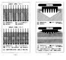
この度開発したこれら新規樹脂硬化機構は、従来技術の代表である高UV硬化性樹脂やUV・加熱併用硬化型樹脂の樹脂硬化機構(図5、図6)とも大きく異なっており、この相違に起因して本発明の新規樹脂硬化機構には、フィラー含有物の硬化不良やエネルギー線照射後の加熱の必要性という従来技術の欠点は存在しない。図5(a)、(b)は、従来の高UV硬化性樹脂の樹脂硬化機構を示すもので、(a)のようにエネルギー線遮蔽物質が存在しない場合は、硬化膜厚が厚くとれるという利点はあるが該遮蔽物質があると、(b)に示されるように硬化反応は進行しない。 These newly developed resin curing mechanisms are greatly different from the resin curing mechanisms (Fig. 5 and Fig. 6) of high UV curable resins and UV / heat curable resins that are representative of the prior art. Thus, the novel resin curing mechanism of the present invention does not have the disadvantages of the prior art such as poor curing of the filler-containing material and necessity of heating after irradiation with energy rays. FIGS. 5A and 5B show a resin curing mechanism of a conventional high UV curable resin. When an energy ray shielding substance is not present as in FIG. 5A, the cured film thickness can be increased. Although there is an advantage, when the shielding material is present, the curing reaction does not proceed as shown in (b).
図6(a)、(b)は、従来のUV・加熱併用硬化型樹脂の樹脂硬化機構を示すもので、(b)のUVエネルギー照射による硬化ではエネルギー線遮蔽物質の存在により硬化が進行しないので(下の図の場合)、(a)のようにエネルギー線照射後に加熱を併用して硬化を進行させる必要がある。カーボンクロス材のようなエネルギー線遮蔽物質が存在する場合は、加熱無しでは従来のUV硬化の有する問題点を解消することができない。(a)、(b)いずれの場合も、上の図が該遮蔽物が存在しない場合を、下の図が存在する場合を示している。 6 (a) and 6 (b) show the resin curing mechanism of a conventional UV / heat combination curable resin, and curing by UV energy irradiation in (b) does not proceed due to the presence of an energy ray shielding substance. Therefore (in the case of the lower figure), as shown in (a), it is necessary to advance curing by using heating together after irradiation with energy rays. When an energy ray shielding material such as a carbon cloth material is present, the problems of conventional UV curing cannot be solved without heating. In both cases (a) and (b), the upper figure shows the case where the shielding object is not present, and the lower figure is present.
次に本発明者らは上記の新規樹脂硬化機構及びかかる樹脂硬化方法を可能とする重合反応開始剤について鋭意研究した結果、光重合開始剤と光及び熱の双方で重合を開始させる光・熱重合開始剤を用いる少なくとも2元系の光重合開始剤系(反応触媒系)が本発明の目的の達成に有用であるとの知見を得た。 Next, as a result of intensive studies on the above-described novel resin curing mechanism and a polymerization reaction initiator that enables such a resin curing method, the present inventors have found that light / heat that initiates polymerization with both a photopolymerization initiator and light and heat. The present inventors have found that at least a binary photopolymerization initiator system (reaction catalyst system) using a polymerization initiator is useful for achieving the object of the present invention.
ここで光重合開始剤として、例えば、下記表Aに示すようなジアゾニウム塩タイプの化合物、表Bに示すようなヨードニウム塩タイプの化合物、下記一般式 Here, as a photopolymerization initiator, for example, a diazonium salt type compound as shown in Table A below, an iodonium salt type compound as shown in Table B, and the following general formula
に示されるようなピリジニウム塩タイプの化合物、特許文献4及び5に示されるようなホスホニウム塩タイプの化合物、下記表Cに示されるようなスルホニウム塩タイプの化合物(後述の実施例表1参照)、表1に示される開始剤(9) (本明細書において開始剤及びオリゴマーの番号は( )付き数字で示すが、表及び図中では丸囲み数字で表示)のような鉄−アレン化合物タイプの化合物及びスルホン酸エステルタイプの化合物の少なくとも1種と、光・熱重合開始剤として、一般式(I)ないし(VII) で示されるスルホニウム塩の少なくとも1種を組合せるのが好ましい。
A compound of a pyridinium salt type as shown in FIG. 5, a compound of a phosphonium salt type as shown in
更にラジカル光開始剤としては次の表D及び表Eに示されるものが用いられる。 Further, as the radical photoinitiator, those shown in the following Table D and Table E are used.
一般式(I)ないし(III) で表される化合物の具体例としては、後述の実施例で用いている光重合開始剤(1) 〜(3) 等が挙げられる(非特許文献1参照)。
一般式(IV)で表される化合物の具体例としては、ビス〔4−(ジメチルスルホニオ)フェニル〕スルフィドビス−ヘキサフルオロホスフェート、ジメチル−4−チオフェノキシフェニルスルホニウムヘキサフルオロアンチモネート等が挙げられる。一般式(V)で表される化合物の具体例としてはジベンジル−4−ヒドロキシフェニルスルホニウムヘキサフルオロアンチモネートが挙げられ、一般式(VI)で表される化合物の具体例としてはベンジル−4−(エトキシカルボニルオキシ)フェニルメチルスルホニウムヘキサフルオロアンチモネートが挙げられ、一般式(VII) で表される化合物の具体例としては4−アセトキシフェニルジメチルスルホニウムヘキサフルオロアンチモネートが挙げられる。
Specific examples of the compounds represented by the general formulas (I) to (III) include photopolymerization initiators (1) to (3) used in Examples described later (see Non-Patent Document 1). .
Specific examples of the compound represented by the general formula (IV) include bis [4- (dimethylsulfonio) phenyl] sulfide bis-hexafluorophosphate, dimethyl-4-thiophenoxyphenylsulfonium hexafluoroantimonate, and the like. . Specific examples of the compound represented by the general formula (V) include dibenzyl-4-hydroxyphenylsulfonium hexafluoroantimonate, and specific examples of the compound represented by the general formula (VI) include benzyl-4- ( Ethoxycarbonyloxy) phenylmethylsulfonium hexafluoroantimonate, and a specific example of the compound represented by the general formula (VII) is 4-acetoxyphenyldimethylsulfonium hexafluoroantimonate.
更に別の組合せとしては、光重合開始剤に表Cに示されるようなアリール系スルホニウム塩タイプの化合物(トリアリールスルホニウム塩、例えば表1の光開始剤(6) )の少なくとも1種と光・熱重合開始剤に上記のような一般式(I)ないし(III) で示されるスルホニウム塩の少なくとも1種を含む2元系以上からなる光重合開始剤系(反応触媒系)が好ましい例として挙げられる。 As yet another combination, at least one kind of aryl type sulfonium salt type compound as shown in Table C (triarylsulfonium salt, for example, photoinitiator (6) in Table 1) as shown in Table C is used as a photopolymerization initiator. Preferred examples of the thermal polymerization initiator include a photopolymerization initiator system (reaction catalyst system) comprising at least one of the above-described sulfonium salts represented by the general formulas (I) to (III). It is done.
更に本発明者らは、上記の研究を更に進めた結果、光・熱重合開始剤として熱に対する触媒作用が高い光・熱重合開始剤、例えば前記一般式(I)ないし(III) で表される化合物(表1の光開始剤(1) 〜(3) )の使用が好ましく、また、熱重合開始剤としては、例えば、化学式(VIII)で表されるれるプレニル・テトラメチレンスルホニウムヘキサフルオロアンチモネート及び化学式 (IX) で表される2−ブチニルテトラメチレンスルホニウムヘキサフルオロアンチモネートの使用が好ましいことを発見した。 Further, as a result of the further progress of the above research, the inventors of the present invention have developed photo / thermal polymerization initiators having high catalytic action against heat as photo / thermal polymerization initiators, such as those represented by the general formulas (I) to (III). The compounds (photoinitiators (1) to (3) in Table 1) are preferably used, and examples of the thermal polymerization initiator include prenyl tetramethylenesulfonium hexafluoroantimony represented by the chemical formula (VIII). We have found that it is preferable to use the 2-butynyltetramethylenesulfonium hexafluoroantimonate represented by the formula (IX).
最後に上記した新規な樹脂硬化機構及びかかる樹脂硬化方法を可能にする樹脂組成物についても同様に鋭意研究した結果、次の知見を得た。すなわち、2元系以上からなる光重合開始剤と光重合性オリゴマーや光重合性モノマーからなる樹脂組成物、及びかかる成形物が有用であることが判明した。特に、カチオン系光重合性オリゴマーやカチオン系光重合性モノマー又は光重合性エポキシオリゴマーや光重合性エポキシモノマーの適用が好ましい。この種の光重合性オリゴマーの例としては脂環式エポキシ、グリシジルエーテル型エポキシ、エポキシ化ポリオレフィン、エポキシ(メタ)アクリレート、ポリエステルアクリレート、ビニルエーテル化合物等が挙げられ、光重合性モノマーの例としてはエポキシモノマー、アクリルモノマー、ビニルエーテル、環状エーテル等が挙げられる。なかでも光重合性脂環式エポキシオリゴマーや光重合性脂環式エポキシモノマーが好ましく、光重合性脂環式オリゴマーとしては、特に3,4−エポキシシクロヘキシルメチル−3,4−エポキシシクロヘキサンカルボキシレートが好ましい。 Finally, the following findings were obtained as a result of intensive studies on the above-described novel resin curing mechanism and the resin composition enabling the resin curing method. That is, it turned out that the resin composition which consists of a photoinitiator which consists of a binary system or more, a photopolymerizable oligomer, a photopolymerizable monomer, and such a molding are useful. In particular, application of a cationic photopolymerizable oligomer, a cationic photopolymerizable monomer, a photopolymerizable epoxy oligomer, or a photopolymerizable epoxy monomer is preferable. Examples of this type of photopolymerizable oligomer include alicyclic epoxy, glycidyl ether type epoxy, epoxidized polyolefin, epoxy (meth) acrylate, polyester acrylate, vinyl ether compound, etc., and examples of photopolymerizable monomers include epoxy. Monomers, acrylic monomers, vinyl ethers, cyclic ethers and the like can be mentioned. Among these, a photopolymerizable alicyclic epoxy oligomer and a photopolymerizable alicyclic epoxy monomer are preferable. As the photopolymerizable alicyclic oligomer, 3,4-epoxycyclohexylmethyl-3,4-epoxycyclohexanecarboxylate is particularly preferable. preferable.
特に光重合開始剤として、表Cに示されるようなアリール系スルホニウム塩タイプ(トリアリールスルホニウム塩、例えば表1の光開始剤(6) )の少なくとも1種と光・熱重合開始剤として前述のような一般式(I)ないし(III) で示されるスルホニウム塩の少なくとも1種とを含む少なくとも2元系以上からなる光重合開始剤系と例えば、3,4−エポキシシクロヘキシルメチル−3,4−エポキシシクロヘキサンカルボキシレートのような光重合性エポキシモノマーもしくはオリゴマーの少なくとも1種からなる樹脂組成物及びそれより得られる成形物が好ましい。 In particular, as the photopolymerization initiator, at least one of aryl sulfonium salt types (triarylsulfonium salts such as the photoinitiator (6) in Table 1) as shown in Table C and the photo / thermal polymerization initiator described above are used. A photopolymerization initiator system comprising at least a binary system containing at least one sulfonium salt represented by the general formulas (I) to (III), and 3,4-epoxycyclohexylmethyl-3,4- A resin composition comprising at least one photopolymerizable epoxy monomer or oligomer such as epoxycyclohexanecarboxylate and a molded product obtained therefrom are preferred.
本発明において上記樹脂組成物の好ましい組成比は光重合性樹脂成分(光重合性のオリゴマーやモノマー)100重量部に対し、2元系以上からなる光重合開始剤系(反応触媒系)成分が0.5〜6.0重量部、好ましくは1.5〜3.5重量部で、且つ光重合開始剤系成分を構成する光・熱重合開始剤/光重合開始剤の重量比が1〜4、好ましくは1.3〜2.8である。2元系以上からなる光重合開始剤の割合が0.5重量部未満ではその効果が殆どなく、全体に対する量が少ないためそのものが機能しにくく、また、6.0重量部を超えても光硬化機能そのものは変わらない。光・熱重合開始剤/光重合開始剤の重量比が1より小さいと、硬化初期の発熱が得にくく、本発明の特徴である硬化機能が発揮しにくいため樹脂表面のみの硬化となり、また、4を超えると硬化特性、特にその発熱特性が異常に高まるため急激な発熱硬化により樹脂が発泡するという問題が生じる。(関連データ:表3,図9及び表4,図10)。 In the present invention, a preferable composition ratio of the resin composition is that a photopolymerization initiator system (reaction catalyst system) component consisting of a binary system or more with respect to 100 parts by weight of a photopolymerizable resin component (photopolymerizable oligomer or monomer). 0.5 to 6.0 parts by weight, preferably 1.5 to 3.5 parts by weight, and the weight ratio of photo / thermal polymerization initiator / photopolymerization initiator constituting the photopolymerization initiator system component is 1 to 1. 4, preferably 1.3 to 2.8. If the proportion of the photopolymerization initiator composed of two or more systems is less than 0.5 parts by weight, the effect is hardly obtained, and since the amount relative to the whole is small, the function itself is difficult to function. The curing function itself does not change. If the weight ratio of the photo / thermal polymerization initiator / photopolymerization initiator is smaller than 1, heat generation at the initial stage of curing is difficult to obtain, and the curing function that is a feature of the present invention is difficult to be exhibited, so only the resin surface is cured, If the number exceeds 4, the curing characteristics, particularly the heat generation characteristics, are abnormally increased, so that there is a problem that the resin is foamed by rapid heat curing. (Related data: Table 3, FIG. 9 and Table 4, FIG. 10).
更には、上記の樹脂組成物に硬化可能な範囲で添加することのできる添加剤としては、エネルギー線遮蔽性物質〔例えば炭素及び炭素繊維(短繊維、長繊維、連続繊維、カーボンクロス等)、無機フィラー、金属粉等〕及び各種フィラー、有機成分、光増感剤、反応性希釈剤、光鋭感剤等慣用される添加剤を1種以上添加することができる。 Furthermore, as an additive that can be added to the above resin composition within a curable range, energy ray shielding substances (for example, carbon and carbon fibers (short fibers, long fibers, continuous fibers, carbon cloth, etc.), Inorganic fillers, metal powders, etc.] and various fillers, organic components, photosensitizers, reactive diluents, photosensitizers and other commonly used additives can be added.
更に本発明者らは、FRP特にCFRPを製造する際、高加工コストの原因として(長時間の)加熱硬化工程が挙げられること、装置・設備の小型化できないのは大型FRPの硬化には大型加熱炉が必要であること、短時間硬化樹脂を大型FRPに使用できないのは硬化開始時間を任意にコントロールできないためであること、含浸状態の保持が難しく成形が困難であるのは製造過程での加熱により樹脂粘度が変化するためであること、品質低下の要因であるボイドの発生は残留溶剤に起因することに着目して、加熱工程が不要で、短時間で硬化し、樹脂硬化開始時間を任意にコントロールでき、溶媒を必要としないFRP特にCFRPの製造方法について鋭意研究した結果、本発明のかかる樹脂組成物をマトリクス樹脂として用いてこれを繊維に含浸させた後、本発明の新規樹脂硬化機構、及び樹脂硬化方法を利用して、UVに代表されるエネルギー線によりFRP及びCFRPを硬化させるFRP及びCFRPの製造方法、及びかかる製造物を開発した。なお本発明で製造物とは建築物、構造物以外の人工的に製造可能な物で本発明の適用範囲内の物をいう。 Furthermore, when manufacturing FRP, in particular CFRP, the high processing cost is caused by a (long-time) heat-curing process, and the size of the apparatus / equipment cannot be reduced. The reason why a heating furnace is necessary, that a short time curing resin cannot be used for a large FRP is that the curing start time cannot be controlled arbitrarily, and it is difficult to maintain the impregnation state and molding is difficult in the manufacturing process. Focusing on the fact that the viscosity of the resin changes due to heating, and that the generation of voids, which is a cause of quality degradation, is caused by the residual solvent. As a result of diligent research on a method for producing FRP, particularly CFRP, which can be arbitrarily controlled and does not require a solvent, the resin composition of the present invention is used as a matrix resin. After impregnating the fiber, using the novel resin curing mechanism and resin curing method of the present invention, FRP and CFRP production method for curing FRP and CFRP with energy rays typified by UV, and such products developed. In the present invention, a product means a product that can be artificially manufactured other than a building or a structure and is within the scope of the present invention.
従来技術の代表であるUV硬化と加熱硬化を併用したフィラメントワインディング成形法では、UV硬化は表面の硬化と内部の増粘のみに関与し、結局全体の硬化は従来同様加熱により硬化させる。従って、従来技術は加熱硬化過程に関係する加工コストや作業時間等の様々な問題点や、大型FRPの成形時の大型加熱炉の必要性等の問題点は未解決のままであるが、本発明のかかるFRP及びCFRP製造方法にはかかる問題点は存在しない。 In the filament winding molding method using both UV curing and heat curing, which is representative of the prior art, UV curing is concerned only with surface curing and internal thickening, and eventually the entire curing is cured by heating as in the prior art. Therefore, the conventional technology still has unsolved various problems such as processing cost and working time related to the heat curing process and the necessity of a large heating furnace when molding a large FRP. Such FRP and CFRP manufacturing methods of the invention do not have such problems.
また、本発明を用いたFRPは、強化繊維として炭素繊維、ガラス繊維、有機繊維など通常のFRPの強化繊維として使用されているものはいずれの繊維も使用することができるし、繊維の形態も一方向に揃えたもの及び織物及び編み物などいかなる形態のものであっても差し支えない。さらに炭素繊維とガラス繊維あるいは炭素繊維とこれらのハイブリットでも良く、特に制限されるものではない。更にFRPの成形方法(図7及び図8)として通常のFRP成形方法を含めたハンドレイアップ、スプレーアップ、フィラメントワインディング、テープワインディング、ロールワインディング、引き抜き成形、ロールプレス連続成形等の成形方法が可能である。 Moreover, as for the FRP using the present invention, any fiber that is used as a reinforcing fiber of normal FRP such as carbon fiber, glass fiber, and organic fiber can be used as the reinforcing fiber, and the form of the fiber is also used. It can be in any form, such as aligned in one direction and woven and knitted. Further, carbon fiber and glass fiber or carbon fiber and a hybrid thereof may be used, and are not particularly limited. Furthermore, FRP molding methods (Figs. 7 and 8) include hand lay-up, spray-up, filament winding, tape winding, roll winding, pultrusion molding, roll press continuous molding, etc., including normal FRP molding methods. It is.
以下本発明を実施例により更に詳細に説明するが限定を意図するものではない。
〔実施例1〕ERL−4221(ユニオンカーバイド(株)製:脂環式エポキシ樹脂;3,4−シクロヘキシルメチル−3,4−エポキシシクロヘキサンカルボキシレート)100重量部に対し、サンエイドSI−80L(三新化学(株)製:カチオン系光・熱重合開始剤;一般式(II))1.75重量部、DAICAT11(ダイセル化学工業(株)製:カチオン系光重合開始剤;アリール系スルホニウム塩)0.75重量部を配合した。(A)
次に上部以外の周囲を黒紙で覆ったガラス容器(φ40mm×H80mm)にかかる樹脂をガラス容器上端まで注入した。(B)
これにUVを60sec照射した。UV照射条件はUV照射装置:UVL−1500M2(ウシオ電機(株))、ランプ種類:メタルハライドランプ、ランプ強度:120W/cm、ランプ長:125mm、雰囲気・温度・圧力:空気中・室温・大気圧、照射距離:19cmで行った。(C)
UV照射後、数分でガラス容器の樹脂は完全に硬化し、樹脂の肉厚はガラス容器の限界である80mm(測定最大値)であった。
The invention will now be described in more detail by way of examples, which are not intended to be limiting.
[Example 1] ERL-4221 (manufactured by Union Carbide Co., Ltd .: alicyclic epoxy resin; 3,4-cyclohexylmethyl-3,4-epoxycyclohexanecarboxylate) 100 parts by weight of sun aid SI-80L (three Shin Chemical Co., Ltd .: Cationic photo / thermal polymerization initiator; 1.75 parts by weight of general formula (II)), DAICAT11 (Daicel Chemical Industries, Ltd .: Cationic photopolymerization initiator; aryl sulfonium salt) 0.75 part by weight was blended. (A)
Next, the resin concerning a glass container (φ40 mm × H80 mm) whose surroundings other than the upper part were covered with black paper was poured to the upper end of the glass container. (B)
This was irradiated with UV for 60 seconds. UV irradiation conditions are UV irradiation apparatus: UVL-1500M2 (Ushio Electric Co., Ltd.), lamp type: metal halide lamp, lamp intensity: 120 W / cm, lamp length: 125 mm, atmosphere / temperature / pressure: in air / room temperature / atmospheric pressure The irradiation distance was 19 cm. (C)
After UV irradiation, the resin in the glass container was completely cured within a few minutes, and the thickness of the resin was 80 mm (maximum value measured), which is the limit of the glass container.
〔実施例2ないし実施例245及び比較例1ないし比較例187〕表1に示す樹脂組成物を用い、表2及び表3に示す組成比で試験を行う以外は実施例1と同様の条件にて試験した。試験結果は表2及び表3並びに表4と図9の結果となった。また、硬化発熱による樹脂温測定データは図10の結果となった。 [Examples 2 to 245 and Comparative Examples 1 to 187] The same conditions as in Example 1 were used except that the resin compositions shown in Table 1 were used and the tests were conducted at the composition ratios shown in Tables 2 and 3. And tested. The test results were as shown in Tables 2 and 3 and Tables 4 and 9. Moreover, the resin temperature measurement data by the heat_generation | fever of hardening became the result of FIG.
〔実施例246〕実施例1の(A)と同様の樹脂組成物を調製し、(B)と同様の方法にてサンプルを準備した。
照射距離:25cm以外は実施例1の(C)と同様の条件にてUVを照射した。UV照射後、数分でガラス容器の樹脂は完全に硬化し、樹脂の肉厚はガラス容器の限界である80mm(測定最大値)であった(関連図:図11)。
[Example 246] A resin composition similar to that in (A) of Example 1 was prepared, and a sample was prepared by the same method as in (B).
Irradiation distance: UV was irradiated under the same conditions as in (C) of Example 1 except for 25 cm. After UV irradiation, the resin in the glass container was completely cured within a few minutes, and the thickness of the resin was 80 mm (maximum measured value), which is the limit of the glass container (related figure: FIG. 11).
〔実施例247〕実施例1の(A)と同様の樹脂組成物を調製し、(B)と同様の方法にてサンプルを準備した。
照射距離:20cm以外は実施例1の(C)と同様の条件にてUVを照射した。UV照射後、数分でガラス容器の樹脂は完全に硬化し、樹脂の肉厚はガラス容器の限界である80mm(測定最大値)であった(関連図:図11)。
[Example 247] A resin composition similar to that in (A) of Example 1 was prepared, and a sample was prepared by the same method as in (B).
Irradiation distance: UV was irradiated under the same conditions as in Example 1 (C) except for 20 cm. After UV irradiation, the resin in the glass container was completely cured within a few minutes, and the thickness of the resin was 80 mm (maximum measured value), which is the limit of the glass container (related figure: FIG. 11).
〔実施例248〕実施例1の(A)と同様の樹脂組成物を調製し、(B)と同様の方法にてサンプルを準備した。
照射距離:15cm以外は実施例1の(C)と同様の条件にてUVを照射した。UV照射後、数分でガラス容器の樹脂は完全に硬化し、樹脂の肉厚はガラス容器の限界である80mm(測定最大値)であった(関連図:図11)。
Example 248 A resin composition similar to that in (A) of Example 1 was prepared, and a sample was prepared by the same method as in (B).
Irradiation distance: UV was irradiated under the same conditions as in (C) of Example 1 except for 15 cm. After UV irradiation, the resin in the glass container was completely cured within a few minutes, and the thickness of the resin was 80 mm (maximum measured value), which is the limit of the glass container (related figure: FIG. 11).
〔実施例249〕実施例1の(A)と同様の樹脂組成物を調製し、(B)と同様の方法にてサンプルを準備した。
UV照射装置:UVL−3500M2(ウシオ電機(株))、ランプ種類:メタルハライドランプ、ランプ強度:120W/cm、ランプ長:250mm、雰囲気・温度・圧力:空気中・室温・大気圧、照射距離:19cm、照射時間:60secの条件にてサンプルにUVを照射した。(D)
UV照射後、数分でガラス容器の樹脂は完全に硬化し、樹脂の肉厚はガラス容器の限界である80mm(測定最大値)であった。
Example 249 A resin composition similar to that in (A) of Example 1 was prepared, and a sample was prepared by the same method as in (B).
UV irradiation device: UVL-3500M2 (Ushio Electric Co., Ltd.), lamp type: metal halide lamp, lamp intensity: 120 W / cm, lamp length: 250 mm, atmosphere / temperature / pressure: in air / room temperature / atmospheric pressure, irradiation distance: The sample was irradiated with UV under the conditions of 19 cm and irradiation time: 60 sec. (D)
After UV irradiation, the resin in the glass container was completely cured within a few minutes, and the thickness of the resin was 80 mm (maximum value measured), which is the limit of the glass container.
〔実施例250〕実施例1の(A)と同様の樹脂組成物を調製し、(B)と同様の方法にてサンプルを準備した。
ランプ強度:200W/cm以外は実施例247の(D)と同様の条件にてUVを照射した。UV照射後、数分でガラス容器の樹脂は完全に硬化し、樹脂の肉厚はガラス容器の限界である80mm(測定最大値)であった。
[Example 250] A resin composition similar to that in (A) of Example 1 was prepared, and a sample was prepared by the same method as in (B).
Lamp intensity: UV was irradiated under the same conditions as in Example 247 (D) except for 200 W / cm. After UV irradiation, the resin in the glass container was completely cured within a few minutes, and the thickness of the resin was 80 mm (maximum value measured), which is the limit of the glass container.
〔実施例251〕実施例1の(A)と同様の樹脂組成物を調製し、(B)と同様の方法にてサンプルを準備した。
ランプ強度:280W/cm以外は実施例247の(D)と同様の条件にてUVを照射した。UV照射後、数分でガラス容器の樹脂は完全に硬化し、樹脂の肉厚はガラス容器の限界である80mm(測定最大値)であった。
[Example 251] A resin composition similar to that in (A) of Example 1 was prepared, and a sample was prepared in the same manner as in (B).
Lamp intensity: UV was irradiated under the same conditions as in Example 247 (D) except for 280 W / cm. After UV irradiation, the resin in the glass container was completely cured within a few minutes, and the thickness of the resin was 80 mm (maximum value measured), which is the limit of the glass container.
〔実施例252〕実施例1の(A)と同様の樹脂組成物を調製したものをマトリクス樹脂とし、これを18cm×18のCFクロスに含浸させてプリプレグを作製した。(E)このプリプレグを40枚積層(約8mm)しバグフィルムを介してガラス板に挟んだ後上から重りをかけ、プリプレグ積層サンプルを作製した(図12)。(E)
照射時間:3min、照射距離:15cm以外は実施例1の(C)と同様の条件にてUV照射した。UV照射後、積層板は完全に硬化し、良好なCFRPを得た(関連データ:表5)。
[Example 252] A prepreg was prepared by impregnating an 18 cm x 18 CF cloth with a matrix resin obtained by preparing the same resin composition as in Example 1 (A). (E) 40 sheets of this prepreg were laminated (about 8 mm) and sandwiched between glass plates via a bag film, and then weighted from above to prepare a prepreg laminated sample (FIG. 12). (E)
UV irradiation was performed under the same conditions as in Example 1 (C) except for irradiation time: 3 min and irradiation distance: 15 cm. After UV irradiation, the laminate was fully cured and good CFRP was obtained (related data: Table 5).
〔実施例253〕強化繊維に18×18のGFクロスを含浸させた以外は、実施例252の(E)と同様にしてプリプレグ積層サンプルを作製した(積層厚さ:約8mm)。実施例252と同様の条件にてUVを照射した。UV照射後、積層板は完全に硬化し、良好なGFRPを得た(関連データ:表5)。 [Example 253] A prepreg laminated sample was produced in the same manner as in Example 252 (E) except that the reinforcing fiber was impregnated with 18 x 18 GF cloth (lamination thickness: about 8 mm). UV was irradiated under the same conditions as in Example 252. After UV irradiation, the laminate was fully cured and good GFRP was obtained (related data: Table 5).
〔実施例254〕プリプレグを100枚積層(約20mm)する以外は、実施例252の(E)と同様にしてプリプレグ積層サンプルを作製した。実施例252と同様の条件にてUVを照射した。UV照射後、積層板は完全に硬化し、良好なCFRPを得た。 [Example 254] A prepreg laminated sample was prepared in the same manner as in Example 252 (E) except that 100 prepregs were laminated (about 20 mm). UV was irradiated under the same conditions as in Example 252. After UV irradiation, the laminate was completely cured and a good CFRP was obtained.
〔実施例255〕マトリクス樹脂に実施例13の樹脂組成物を用いる以外は、実施例252の(E)と同様にしてプリプレグ積層サンプルを作製した。実施例252と同様の条件にてUVを照射した。UV照射後、積層板は完全に硬化し、良好なCFRPを得た。 [Example 255] A prepreg laminated sample was prepared in the same manner as in Example 252 (E) except that the resin composition of Example 13 was used as the matrix resin. UV was irradiated under the same conditions as in Example 252. After UV irradiation, the laminate was completely cured and a good CFRP was obtained.
〔実施例256〕実施例252の(E)と同様にしてプリプレグ積層サンプルを作製した。エネルギー線として電子線(EB)を用いた。照射条件は、照射装置:ライナック(ハイボルテージアルコ(株)、ビームエネルギー:10MeV、スキャン周波数:4Hz、パルス繰り返し数:60Hz、スキャン幅:20cm、パルス幅:4μsec、放射線量:50kGyで照射した。UV照射後、積層板は完全に硬化し、良好なCFRPを得た。 Example 256 A prepreg laminated sample was produced in the same manner as in Example 252 (E). An electron beam (EB) was used as the energy beam. Irradiation conditions were as follows: irradiation apparatus: Linac (High Voltage Arco Co., Ltd., beam energy: 10 MeV, scan frequency: 4 Hz, pulse repetition rate: 60 Hz, scan width: 20 cm, pulse width: 4 μsec, radiation dose: 50 kGy. After UV irradiation, the laminate was completely cured and a good CFRP was obtained.
〔実施例257〕実施例252の(E)と同様の方法にてマトリクス樹脂を作製し、これを炭素繊維に含浸させた後、巻き付け速度30cm/secにて巻き取って(フィラメントワインディング法)によりCFRP製の円筒積層材を成形(板厚3mm)した(F)
完全に巻き終わった後、円筒積層材に全方向からUVを照射(照射条件は、実施例252と同様の条件)した。UV照射後、積層板は完全に硬化し、良好なフィラメントワインディング製CFRPを得た。
[Example 257] A matrix resin was prepared by the same method as in Example 252 (E), impregnated with carbon fiber, and then wound at a winding speed of 30 cm / sec (filament winding method). CFRP cylindrical laminated material was molded (
After complete winding, the cylindrical laminate was irradiated with UV from all directions (irradiation conditions were the same as in Example 252). After the UV irradiation, the laminate was completely cured, and a good filament winding CFRP was obtained.
〔実施例258〕強化繊維にガラス繊維を用いる以外は実施例257の(F)と同様の方法にてGFRP製の円筒積層材を成形(板厚3mm)した。完全に巻き終わった後、円筒積層材に全方向からUVを照射(照射条件は、実施例252と同様の条件)した。UV照射後、積層板は完全に硬化し、良好なフィラメントワインディング製GFRPを得た。 [Example 258] A cylindrical laminate made of GFRP was formed (plate thickness: 3 mm) in the same manner as in Example 257 (F) except that glass fiber was used as the reinforcing fiber. After complete winding, the cylindrical laminate was irradiated with UV from all directions (irradiation conditions were the same as in Example 252). After the UV irradiation, the laminate was completely cured, and a good filament winding GFRP was obtained.
実施例259
セロキサイド2021P(オリゴマー[1]、ダイセル化学工業(株)製:脂環式エポキシ樹脂;3,4−シクロヘキシルメチル−3,4−エポキシシクロヘキサンカルボキシレート)100重量部に対し、サンエイドS1−80L(光開始剤[2]、三新化学(株)製:カチオン系光・熱重合開始剤;一般式(II))1.50重量部、DAICAT11(光開始剤[6]、ダイセル化学工業(株)製:カチオン系光重合開始剤;アリール系スルホニウム塩)0.50重量部、4,4'−ビス〔ジ(竈−ヒドロキシエトキシ)フェニルスルフォニオ〕フェニルスルフィド−ビス−ヘキサフルオロアンチモネート(光開始剤[13])0.50重量部、2−ブチニルテトラメチレンスルホニウムヘキサフルオロアンチモネート(熱開始剤[15]:一般式(IX))0.50重量部を配合した樹脂組成物で試験を行う以外は実施例1と同様の条件にて試験した。UV照射後、数分でガラス容器の樹脂は完全に硬化し、樹脂の肉厚はガラス容器の限界である80mm(測定最大値)であった。
Example 259
For 100 parts by weight of Celoxide 2021P (oligomer [1], manufactured by Daicel Chemical Industries, Ltd .: alicyclic epoxy resin; 3,4-cyclohexylmethyl-3,4-epoxycyclohexanecarboxylate), Sun Aid S1-80L (light Initiator [2], manufactured by Sanshin Chemical Co., Ltd .: Cationic photo / thermal polymerization initiator; 1.50 parts by weight, general formula (II)), DAICAT11 (photoinitiator [6], Daicel Chemical Industries, Ltd.) Manufactured by: Cationic photopolymerization initiator; aryl sulfonium salt) 0.50 parts by weight, 4,4′-bis [di (竈 -hydroxyethoxy) phenylsulfonio] phenyl sulfide-bis-hexafluoroantimonate (light initiator [13]) 0.50 parts by weight, 2-butynyl tetramethylene sulfonium hexafluoroantimonate (thermal initiators [15]: general formula (IX)) 0.50 Except for testing a resin composition containing an amount unit was tested under the same conditions as in Example 1. After UV irradiation, the resin in the glass container was completely cured within a few minutes, and the thickness of the resin was 80 mm (maximum value measured), which is the limit of the glass container.
実施例260
セロキサイド2021P(オリゴマー[1]、ダイセル化学工業(株)製:脂環式エポキシ樹脂;3,4−シクロヘキシルメチル−3,4−エポキシシクロヘキサンカルボキシレート)100重量部に対し、サンエイドSI−80L(光開始剤[2]、三新化学(株)製:カチオン系光・熱重合開始剤;一般式(II))1.50重量部、DAICAT11(光開始剤[6]、ダイセル化学工業(株)製:カチオン系光重合開始剤;アリール系スルホニウム塩)1.00重量部、プレニルテトラメチレンスルホニウムヘキサフルオロアンチモネート(熱開始剤[14]:一般式(VIII))0.50重量部を配合した樹脂組成物で試験を行う以外は実施例1と同様の条件にて試験した。UV照射後、数分でガラス容器の樹脂は完全に硬化し、樹脂の肉厚はガラス容器の限界である80mm(測定最大値)であった。
Example 260
For 100 parts by weight of Celoxide 2021P (oligomer [1], manufactured by Daicel Chemical Industries, Ltd .: alicyclic epoxy resin; 3,4-cyclohexylmethyl-3,4-epoxycyclohexanecarboxylate), Sun Aid SI-80L (light Initiator [2], manufactured by Sanshin Chemical Co., Ltd .: Cationic photo / thermal polymerization initiator; 1.50 parts by weight, general formula (II)), DAICAT11 (photoinitiator [6], Daicel Chemical Industries, Ltd.) Manufactured: Cationic photopolymerization initiator; aryl sulfonium salt (1.00 part by weight) and prenyltetramethylenesulfonium hexafluoroantimonate ( thermal initiator [14]: general formula (VIII)) (0.50 part by weight) The test was performed under the same conditions as in Example 1 except that the test was performed using the resin composition. After UV irradiation, the resin in the glass container was completely cured within a few minutes, and the thickness of the resin was 80 mm (maximum value measured), which is the limit of the glass container.
〔比較例188ないし比較例190〕樹脂組成物として比較例1の組成物を用いる以外は、全て実施例246ないし実施例248の方法にて試験した。UV照射後の樹脂の肉厚は1mm程度で内部は未硬化であった。(関連図:図11)。 [Comparative Examples 188 to 190] All tests were conducted by the methods of Examples 246 to 248 except that the composition of Comparative Example 1 was used as the resin composition. The thickness of the resin after UV irradiation was about 1 mm and the inside was uncured. (Related diagram: FIG. 11).
〔比較例191〕比較例1の樹脂組成物をマトリクス樹脂に用いる以外は、実施例252の(E)と同様にしてプリプレグ積層サンプルを作製した。実施例252と同様の条件にてUVを照射した。UV照射後のCFRPは、照射面1層目の表層の部分しか硬化せず、樹脂内部は完全に未硬化であった。 [Comparative Example 191] A prepreg laminated sample was prepared in the same manner as in Example 252 (E) except that the resin composition of Comparative Example 1 was used for the matrix resin. UV was irradiated under the same conditions as in Example 252. CFRP after UV irradiation cured only the surface layer portion of the first irradiated surface, and the resin interior was completely uncured.
〔比較例192〕比較例1の樹脂組成物をマトリクス樹脂に用いる以外は、実施例253と同様にしてプリプレグ積層サンプルを作製した。実施例252と同様の条件にてUVを照射した。UV照射後のGFRPは、照射面2ないし3層目部分までしか硬化せず、樹脂内部は完全に未硬化であった。 [Comparative Example 192] A prepreg laminated sample was prepared in the same manner as in Example 253 except that the resin composition of Comparative Example 1 was used as the matrix resin. UV was irradiated under the same conditions as in Example 252. The GFRP after UV irradiation cured only to the 2nd to 3rd layer portions of the irradiated surface, and the inside of the resin was completely uncured.
〔実施例261ないし実施例282〕表1に示す樹脂組成物を用い、表6に示す樹脂組成比(表2につづく)で試験を行う以外は実施例1と同様の条件で試験した。試験結果は表6に示すとおりとなった。 [Examples 261 to 282] Tests were performed under the same conditions as in Example 1 except that the resin compositions shown in Table 1 were used and the tests were conducted at the resin composition ratios shown in Table 6 (continued from Table 2). The test results are shown in Table 6.
〔実施例283〕実施例1の(A)と同様の樹脂組成物を調製し、(B)と同様の方法にてサンプルを準備した。準備したサンプルにエネルギー線を照射するのではなく、150℃に保持したオーブンに入れ加熱した。加熱開始より十分弱でガラス容器の樹脂は完全に硬化し、樹脂の肉厚はガラス容器の限界である80mm(測定最大値)であった。 Example 283 A resin composition similar to that in (A) of Example 1 was prepared, and a sample was prepared by the same method as in (B). Instead of irradiating the prepared sample with energy rays, it was heated in an oven maintained at 150 ° C. The resin in the glass container was sufficiently cured from the start of heating, and the thickness of the resin was 80 mm (maximum value measured), which is the limit of the glass container.
〔実施例284〕実施例1の(A)と同様の樹脂組成物を調製し、(B)と同様の方法にてサンプルを準備した。準備したサンプルを硬化が開始しない温度範囲(本実施例では60℃)に温度調節したオーブンに入れて、樹脂温度がオーブン内雰囲気温度と同等になるまで保持した。その後サンプルをオーブンより取り出し、実施例1と同様の条件にて試験した。UV照射後、数分(実施例1より短時間)でガラス容器の樹脂は完全に硬化し、樹脂の肉厚はガラス容器の限界である80mm(測定最大値)であった。 [Example 284] A resin composition similar to that in (A) of Example 1 was prepared, and a sample was prepared in the same manner as in (B). The prepared sample was put in an oven adjusted in a temperature range (60 ° C. in this example) where curing does not start, and held until the resin temperature became equal to the atmosphere temperature in the oven. Thereafter, the sample was taken out of the oven and tested under the same conditions as in Example 1. After UV irradiation, the resin in the glass container was completely cured within a few minutes (shorter time than Example 1), and the thickness of the resin was 80 mm (maximum measurement value), which is the limit of the glass container.
〔発明の効果〕
〔新規樹脂硬化機構を可能にする樹脂組成物〕表1〜表3及び表6に記載される実施例1ないし実施例60、実施例259ないし282及び比較例1ないし比較例20の試験結果より新規樹脂硬化機構を備えた本発明の組成物が、エネルギー線硬化性、特に厚肉硬化性に優れていることがわかる。更に、実施例284より、予め本発明の組成物を加温(硬化しない温度範囲)した後にエネルギー線を照射すると硬化により効果的であることがわかる。又、実施例283より2元系以上からなる光開始剤を組成中に含む本発明の組成物は、加熱によっても短時間で硬化することを確認した。
〔The invention's effect〕
[Resin Composition Enabling New Resin Curing Mechanism] From the test results of Examples 1 to 60, Examples 259 to 282 and Comparative Examples 1 to 20 described in Tables 1 to 3 and Table 6. It can be seen that the composition of the present invention equipped with a novel resin curing mechanism is excellent in energy beam curability, particularly thick-wall curability. Furthermore, from Example 284, it can be seen that curing with an energy beam after heating the composition of the present invention in advance (temperature range at which it does not cure) is more effective for curing. Moreover, it confirmed that the composition of this invention which contains the photoinitiator which consists of a binary system or more from Example 283 in a composition hardens | cures in a short time also by a heating.
〔新規樹脂硬化機構を可能にする2元系以上からなる光重合開始剤系とその適正比率〕表1〜表3及び図9に記載されている実施例1ないし実施例245及び比較例1ないし比較例187の試験結果から、新規樹脂硬化機構を可能にする2元系以上からなる光重合開始剤系の有効性とその適正比率が明らかである。 [A Photopolymerization Initiator System Consisting of Two or More Binary Systems Enabling a New Resin Curing Mechanism and Its Appropriate Ratio] Examples 1 to 245 and Comparative Examples 1 to 1 described in Tables 1 to 3 and FIG. From the test results of Comparative Example 187, the effectiveness and appropriate ratio of a photopolymerization initiator system comprising a binary system or more that enables a novel resin curing mechanism is clear.
〔新規樹脂硬化機構の検証〕実施例1ないし実施例245及び比較例1ないし比較例187の結果のうち、表4に記載される組成物のエネルギー線照射時の樹脂の硬化発熱による樹脂温度上昇曲線を図10に示す。また実施例246ないし実施例248及び比較例188ないし比較例190のエネルギー線照射時の樹脂の硬化発熱による樹脂温度上昇曲線を図11に示す。図10、11より本発明樹脂組成は、エネルギー線源からのエネルギーとは別のエネルギー、本事例であれば硬化反応熱(硬化発熱)による熱エネルギーを樹脂内部に自己発生させ、硬化反応による熱エネルギーとエネルギー線源からのエネルギーにより樹脂組成物が硬化する、新規樹脂硬化機構によるものであることが明らかである。また、実施例246ないし実施例251の試験結果から、本発明である新規樹脂硬化機構はエネルギー線の照射条件が変化しても有効であることが確認できる。 [Verification of New Resin Curing Mechanism] Among the results of Examples 1 to 245 and Comparative Examples 1 to 187, the resin temperature rise due to the heat of curing of the resin when irradiated with the energy rays of the compositions described in Table 4 The curve is shown in FIG. Further, FIG. 11 shows resin temperature rise curves due to the heat generated by curing the resin during energy ray irradiation in Examples 246 to 248 and Comparative Examples 188 to 190. 10 and 11, the resin composition of the present invention has energy different from the energy from the energy ray source, in this case, heat energy due to curing reaction heat (curing heat generation) is self-generated inside the resin, and heat due to the curing reaction. It is clear that this is due to a novel resin curing mechanism in which the resin composition is cured by energy and energy from an energy beam source. Further, from the test results of Example 246 to Example 251, it can be confirmed that the novel resin curing mechanism according to the present invention is effective even if the irradiation condition of the energy beam is changed.
〔CFRP(エネルギー線遮蔽性物質含有厚肉樹脂)及びGFRP硬化性の検証〕実施例252ないし実施例258及び比較例191ないし比較例192の結果から、本発明である新規樹脂硬化機構及びこれを可能にする2元系以上よりなる光重合開始剤系並び樹脂組成物が、従来光硬化樹脂ではなしえなかったCFRP(エネルギー線遮蔽性物質含有厚肉樹脂)の光硬化(エネルギー線硬化)及びGFRP等の光硬化(エネルギー線硬化)を実現していることは明らかである。また、実施例256から、本発明である新規樹脂硬化機構及びこれを可能にする2元系以上よりなる光重合開始剤系並び樹脂組成物と、本発明を用いたFRP(CFRP)製造方法はFRP(CFRP)のEB硬化にも適用可能であることが確認できる。さらに、実施例257から本発明によるFRP(CFRP)製造方法はレイアップ法だけでなく他のFRP製造方法、例えばフィラメントワインディング法等にも応用可能であることは明らかである。 [Verification of CFRP (Energy Ray Shielding Substance-Containing Thick Resin) and GFRP Curability] From the results of Examples 252 to 258 and Comparative Examples 191 to 192, the novel resin curing mechanism of the present invention and this The photo-polymerization initiator system and the resin composition composed of two or more binary systems that enable the photo-curing (energy-ray curing) of CFRP (energy beam shielding substance-containing thick resin), which could not be achieved with conventional photo-curing resins, and It is clear that photocuring (energy ray curing) such as GFRP is realized. Further, from Example 256, the novel resin curing mechanism according to the present invention, a photopolymerization initiator system and a resin composition comprising two or more systems enabling this, and the FRP (CFRP) production method using the present invention are as follows. It can be confirmed that the present invention can also be applied to EB curing of FRP (CFRP). Furthermore, from Example 257, it is clear that the FRP (CFRP) manufacturing method according to the present invention can be applied not only to the lay-up method but also to other FRP manufacturing methods such as the filament winding method.
〔本発明により製造したCFRP及びGFRP成形物〕実施例252ないし実施例253で製造したCFRPとGFRPの基礎物性値を測定し、表5に示す。表5より良好なサンプルであることがわかる。 [CFRP and GFRP Molded Articles Produced by the Present Invention] The basic physical properties of CFRP and GFRP produced in Examples 252 to 253 were measured and are shown in Table 5. It turns out that it is a favorable sample from Table 5.
本発明の硬化方法、そのための組成物、成形物及び成形方法は、繊維又は充填材のUV遮蔽性の有無や長さ、大きさ、形状に関係なく有効であり、利用分野も複合材の他に接着剤や封止材、ワニス、塗料、コーティング材、インキ、トナー等の分野に適用可能である。 The curing method of the present invention, the composition therefor, the molded product and the molding method are effective regardless of the presence or absence, length, size, and shape of the UV shielding property of the fiber or filler. In addition, it can be applied to fields such as adhesives, sealants, varnishes, paints, coating materials, inks, and toners.
Claims (10)
エネルギー線の照射により硬化開始させて硬化反応熱を発生させ、該硬化反応熱により硬化反応が連鎖的に進行して硬化反応熱を連続的に発生させ、樹脂組成物中のエネルギー線遮蔽性物質の有無に関わらず、エネルギー線の照射無しで硬化反応の自己発生熱により硬化反応を連鎖的に進行させる特性を有する重合開始剤。 It consists of a binary system having a photopolymerization initiator and a light / thermal polymerization initiator that initiates polymerization with both light and heat as components, and 0.5 parts per 100 parts by weight of the photopolymerizable oligomer or monomer. -6.0 parts by weight, a polymerization initiator having a weight ratio of the photo / thermal polymerization initiator / the photopolymerization initiator of 1 to 4, and
Curing is started by irradiation of energy rays to generate curing reaction heat, and the curing reaction proceeds in a chain by the curing reaction heat to continuously generate curing reaction heat, and the energy ray shielding substance in the resin composition. A polymerization initiator having the property of causing the curing reaction to proceed in a chain manner by the self-generated heat of the curing reaction without irradiation of energy rays, regardless of the presence or absence of .
光・熱重合開始剤として、下記の一般式(I)、(II)、(II)’、(III)、(IV)、(V)、(VI)及び(VII)で示されるスルホニウム塩の少なくとも1種を含むことを特徴とする請求項5に記載の重合開始剤。
As photo / thermal polymerization initiators , sulfonium salts represented by the following general formulas (I), (II), (II) ′, (III), (IV), (V), (VI) and (VII) Polymerization initiator according to claim 5, characterized in that it comprises at least one.
光・熱重合開始剤として、一般式(I)、(II)又は(III)で示されるスルホニウム塩タイプの少なくとも1種を含むことを特徴とする請求項6に記載の重合開始剤。 As a photopolymerization initiator , it contains at least one aryl sulfonium salt type,
As the light-heat polymerization initiator, the general formula (I), Polymerization initiator according to claim 6, characterized in that it comprises at least one sulfonium salt type of formula (II) or (III).
Priority Applications (1)
| Application Number | Priority Date | Filing Date | Title |
|---|---|---|---|
| JP2005113700A JP3944217B2 (en) | 1997-10-17 | 2005-04-11 | Polymerization initiator and method for producing cured resin using the same |
Applications Claiming Priority (2)
| Application Number | Priority Date | Filing Date | Title |
|---|---|---|---|
| JP28529597 | 1997-10-17 | ||
| JP2005113700A JP3944217B2 (en) | 1997-10-17 | 2005-04-11 | Polymerization initiator and method for producing cured resin using the same |
Related Parent Applications (1)
| Application Number | Title | Priority Date | Filing Date |
|---|---|---|---|
| JP28386798A Division JP3950241B2 (en) | 1997-10-17 | 1998-10-06 | Resin composition, cured resin, and structure repair method, reinforcement method, repair material, reinforcement material |
Publications (2)
| Publication Number | Publication Date |
|---|---|
| JP2005206847A JP2005206847A (en) | 2005-08-04 |
| JP3944217B2 true JP3944217B2 (en) | 2007-07-11 |
Family
ID=34913759
Family Applications (1)
| Application Number | Title | Priority Date | Filing Date |
|---|---|---|---|
| JP2005113700A Expired - Lifetime JP3944217B2 (en) | 1997-10-17 | 2005-04-11 | Polymerization initiator and method for producing cured resin using the same |
Country Status (1)
| Country | Link |
|---|---|
| JP (1) | JP3944217B2 (en) |
Cited By (2)
| Publication number | Priority date | Publication date | Assignee | Title |
|---|---|---|---|---|
| WO2013011885A1 (en) | 2011-07-21 | 2013-01-24 | 三菱重工業株式会社 | Method and device for producing at least two products including fiber-reinforced resin |
| WO2014112274A1 (en) | 2013-01-18 | 2014-07-24 | 三菱重工業株式会社 | Method for producing composite material |
Families Citing this family (6)
| Publication number | Priority date | Publication date | Assignee | Title |
|---|---|---|---|---|
| US7964248B2 (en) * | 2007-04-13 | 2011-06-21 | Huntsman Advanced Materials Americas Llc | Dual photoinitiator, photocurable composition, use thereof and process for producing a three dimensional article |
| JP5754073B2 (en) * | 2010-03-17 | 2015-07-22 | 株式会社デンソー | Method for producing cured composite and cured composite |
| JP6743415B2 (en) * | 2016-02-29 | 2020-08-19 | 東洋インキScホールディングス株式会社 | Resin composition for carbon fiber reinforced composite material, carbon fiber member and carbon fiber reinforced composite material |
| EP4230398A1 (en) | 2017-01-20 | 2023-08-23 | Mitsui Chemicals, Inc. | Laminate and tape winding pipe |
| WO2018181290A1 (en) | 2017-03-29 | 2018-10-04 | 三井化学株式会社 | Laminate and method for producing same |
| JP6928679B2 (en) | 2018-01-31 | 2021-09-01 | 三井化学株式会社 | Laminated sheets and laminates, and their manufacturing methods |
-
2005
- 2005-04-11 JP JP2005113700A patent/JP3944217B2/en not_active Expired - Lifetime
Cited By (3)
| Publication number | Priority date | Publication date | Assignee | Title |
|---|---|---|---|---|
| WO2013011885A1 (en) | 2011-07-21 | 2013-01-24 | 三菱重工業株式会社 | Method and device for producing at least two products including fiber-reinforced resin |
| WO2014112274A1 (en) | 2013-01-18 | 2014-07-24 | 三菱重工業株式会社 | Method for producing composite material |
| US10086563B2 (en) | 2013-01-18 | 2018-10-02 | Mitsubishi Heavy Industries, Ltd. | Method of producing composite material |
Also Published As
| Publication number | Publication date |
|---|---|
| JP2005206847A (en) | 2005-08-04 |
Similar Documents
| Publication | Publication Date | Title |
|---|---|---|
| JP3950241B2 (en) | Resin composition, cured resin, and structure repair method, reinforcement method, repair material, reinforcement material | |
| US4156035A (en) | Photocurable epoxy-acrylate compositions | |
| JP3431782B2 (en) | Curable composite material composition and curing method thereof | |
| JPS60135402A (en) | Polymeric composition | |
| JPS6311944B2 (en) | ||
| JPH0753711A (en) | Composition curable by actinic radiation | |
| JP3944217B2 (en) | Polymerization initiator and method for producing cured resin using the same | |
| JP4495217B2 (en) | RTM molding method | |
| JP2001002760A (en) | Hardened composition of resin containing energy ray- shielding material by irradiation with energy ray, and hardening method | |
| Kurtulus et al. | A Novel Route to Glass Fiber‐Reinforced Epoxy Matrix Composites: Visible Light Activated Radical Induced Cationic Frontal Polymerization | |
| JP3461801B2 (en) | Novel polymerization and / or crosslinking initiator system containing onium borate and benzophenone | |
| JP2002256062A (en) | Active energy ray-curable resin composition | |
| Pradhan | Synthesis and advances in rapid curing resins | |
| JPH07173279A (en) | Production of cured material | |
| JP2006281548A (en) | Method for molding visible light curable fiber reinforced resin composite | |
| JP3424772B2 (en) | Photopolymerization initiator, energy ray-curable composition containing the same, and cured product thereof | |
| JP4837187B2 (en) | Active energy ray-curable resin composition | |
| EP0544842A4 (en) | Electron beam curable epoxy compositions | |
| JP4275130B2 (en) | Method for molding coal ash-containing resin composition | |
| JP2004352821A (en) | Active energy ray-curable resin composition for composite material | |
| JPS6121244B2 (en) | ||
| JP2005256008A (en) | Fiber-reinforced composite material using uv cured resin and its manufacturing method | |
| JP2001139872A (en) | Curable coating composition for coating wood | |
| JPH1067812A (en) | Actinic-radiation-curing composition and cured product thereof | |
| AU4663197A (en) | Electron-beam curable epoxy compositions |
Legal Events
| Date | Code | Title | Description |
|---|---|---|---|
| A621 | Written request for application examination |
Free format text: JAPANESE INTERMEDIATE CODE: A621 Effective date: 20050426 |
|
| A521 | Written amendment |
Free format text: JAPANESE INTERMEDIATE CODE: A523 Effective date: 20050704 |
|
| A977 | Report on retrieval |
Free format text: JAPANESE INTERMEDIATE CODE: A971007 Effective date: 20060831 |
|
| A131 | Notification of reasons for refusal |
Free format text: JAPANESE INTERMEDIATE CODE: A131 Effective date: 20060919 |
|
| A521 | Written amendment |
Free format text: JAPANESE INTERMEDIATE CODE: A523 Effective date: 20061120 |
|
| TRDD | Decision of grant or rejection written | ||
| A01 | Written decision to grant a patent or to grant a registration (utility model) |
Free format text: JAPANESE INTERMEDIATE CODE: A01 Effective date: 20070320 |
|
| A61 | First payment of annual fees (during grant procedure) |
Free format text: JAPANESE INTERMEDIATE CODE: A61 Effective date: 20070406 |
|
| FPAY | Renewal fee payment (event date is renewal date of database) |
Free format text: PAYMENT UNTIL: 20100413 Year of fee payment: 3 |
|
| FPAY | Renewal fee payment (event date is renewal date of database) |
Free format text: PAYMENT UNTIL: 20110413 Year of fee payment: 4 |
|
| FPAY | Renewal fee payment (event date is renewal date of database) |
Free format text: PAYMENT UNTIL: 20130413 Year of fee payment: 6 |
|
| FPAY | Renewal fee payment (event date is renewal date of database) |
Free format text: PAYMENT UNTIL: 20140413 Year of fee payment: 7 |
|
| R250 | Receipt of annual fees |
Free format text: JAPANESE INTERMEDIATE CODE: R250 |
|
| EXPY | Cancellation because of completion of term |