JP3918723B2 - Portable electric tool - Google Patents
Portable electric tool Download PDFInfo
- Publication number
- JP3918723B2 JP3918723B2 JP2002343034A JP2002343034A JP3918723B2 JP 3918723 B2 JP3918723 B2 JP 3918723B2 JP 2002343034 A JP2002343034 A JP 2002343034A JP 2002343034 A JP2002343034 A JP 2002343034A JP 3918723 B2 JP3918723 B2 JP 3918723B2
- Authority
- JP
- Japan
- Prior art keywords
- hook
- battery pack
- hooking
- main body
- power tool
- Prior art date
- Legal status (The legal status is an assumption and is not a legal conclusion. Google has not performed a legal analysis and makes no representation as to the accuracy of the status listed.)
- Expired - Fee Related
Links
- 238000003780 insertion Methods 0.000 description 6
- 230000037431 insertion Effects 0.000 description 6
- 230000000694 effects Effects 0.000 description 4
- 239000002184 metal Substances 0.000 description 4
- 230000005540 biological transmission Effects 0.000 description 1
- 238000005553 drilling Methods 0.000 description 1
- 230000013011 mating Effects 0.000 description 1
- 230000002093 peripheral effect Effects 0.000 description 1
- 230000001105 regulatory effect Effects 0.000 description 1
- 239000011347 resin Substances 0.000 description 1
- 229920005989 resin Polymers 0.000 description 1
Images


Classifications
-
- B—PERFORMING OPERATIONS; TRANSPORTING
- B25—HAND TOOLS; PORTABLE POWER-DRIVEN TOOLS; MANIPULATORS
- B25H—WORKSHOP EQUIPMENT, e.g. FOR MARKING-OUT WORK; STORAGE MEANS FOR WORKSHOPS
- B25H3/00—Storage means or arrangements for workshops facilitating access to, or handling of, work tools or instruments
- B25H3/006—Storage means specially adapted for one specific hand apparatus, e.g. an electric drill
-
- B—PERFORMING OPERATIONS; TRANSPORTING
- B25—HAND TOOLS; PORTABLE POWER-DRIVEN TOOLS; MANIPULATORS
- B25F—COMBINATION OR MULTI-PURPOSE TOOLS NOT OTHERWISE PROVIDED FOR; DETAILS OR COMPONENTS OF PORTABLE POWER-DRIVEN TOOLS NOT PARTICULARLY RELATED TO THE OPERATIONS PERFORMED AND NOT OTHERWISE PROVIDED FOR
- B25F5/00—Details or components of portable power-driven tools not particularly related to the operations performed and not otherwise provided for
Landscapes
- Engineering & Computer Science (AREA)
- Mechanical Engineering (AREA)
- Battery Mounting, Suspending (AREA)
- Portable Power Tools In General (AREA)
- Workshop Equipment, Work Benches, Supports, Or Storage Means (AREA)
Description
【0001】
【発明の属する技術分野】
本発明は、作業者の腰ベルト等に引掛ける掛止用フックを有する可搬式電動工具に関する。
【0002】
【従来の技術】
従来から、電動工具本体を作業者の腰ベルト等に引掛けておく為に、掛止用フックを、該掛止用フックに突設した軸部を中心として回転自在に電動工具本体に接続させた可搬式電動工具が提案されている(特許文献1参照)。しかしながら、このものにおいては、掛止用フックが電動工具本体に接続した電池パックの幅からはみ出て位置するようになっており、電動工具本体が小型であっても全体としては大型化してしまうとともに、電動工具本体が落下した場合には、掛止用フックが先に地面等に衝突して破損が生じ易いものであった。加えて、掛止用フックは常にその軸部側でのみ支持されているので、落下等の衝撃により軸部側に負荷が集中することでも破損し易いものであった。
【0003】
【特許文献1】
特開2002−254358号公報
【0004】
【発明が解決しようとする課題】
本発明は上記の点に鑑みてなされたものであり、電動工具本体が落下した場合でも掛止用フックに破損を生じることが防止されるコンパクトな電動工具を提供することを課題とするものである。
【0005】
【課題を解決するための手段】
上記課題を解決するために本発明を、モータを内蔵する電動工具本体の本体ハウジングに幅広の電池パック取付部を形成するとともに、該電池パック取付部にモータの駆動源である電池パックを接続し、へ字状に形成したハンドル部とこれの根元部分に突設した軸部とから成る掛止用フックを、電池パックを接続した側を下側としたときの左右方向を回転軸方向として該軸部を中心に回転自在となるように、電動工具本体の電池パック取付部近傍に接続させた可搬式電動工具において、前記掛止用フックの回転軸方向の端部位置を電池パックの幅内に納めることを特徴としたものとする。このようにすることで、掛止用フックまで含めた全体として可搬式電動工具がコンパクト化されるとともに、掛止用フックの装着、未装着によって可搬式電動工具全体の寸法に生じる寸法の差が小さくなって収納ケース等を共用することが容易になる。加えて、電動工具本体が落下した場合にも、掛止用フックが先に地面等に衝突して破損を生じることが回避される。
【0006】
また、掛止用フックの設定可能な角度として、掛止用フックの先端部が電池パック取付部と当接する角度を備えることも好ましい。このようにすることで、落下等により掛止用フックが衝撃を受けた場合も軸部側にだけ負荷が集中するのでなく先端側にも分散されて、掛止用フックの破損を更に確実に防止されることとなる。
【0007】
【発明の実施の形態】
以下、本発明を添付図面に示す実施の形態に基づいて説明する。図5には、本発明の実施の形態における一例の可搬式電動工具の全体を示している。一例の可搬式電動工具は、電動工具本体1と電池パック2とで主体を構成する電動ドライバであって、電動工具本体1の略T型を成す本体ハウジング3内には、動力源である電池パック2から供給される電気エネルギにより回転駆動されるモータ4と、モータ4への電気エネルギの入り切りを操作するスイッチ5と、モータ4の回転を締結作業や穴あけ作業に適した回転数等に変換して伝達する減速機ブロック6とを備え、スイッチ5の操作に基づいてモータ4の回転力をチャック7に保持した先端工具(図示せず)にまで伝達して作業を行うものである。なお、以下の説明文中において、電動工具本体1のチャック7を設けた側を正面側、電池パック2を接続した側を下側とする。
【0008】
図3、図4に示すように、本体ハウジング3の把持部分であるグリップ部3aの背面には、フック保持部8を背方に向けて延設している。フック保持部8は本体ハウジング3と同一の樹脂によって同時に成形されるものであり、両側方に開口した貫通穴9を備えて略円筒状をしている。貫通穴9を構成する中央穴部10と両側穴部11,11とでは、中央穴部10が両側穴部11,11よりも段部12,12を介して小径に形成されており、上記中央穴部10が後述する掛止用フック16の挿入穴13となっている。いずれの段部12,12にも、挿入穴13の軸方向に向けて波型の凹凸を成す係合部14,14を突設しており、また、いずれの側穴部11,11の内周壁にも、回転規制溝15,15を周方向に伸びるように凹設している。
【0009】
掛止用フック16は、略ヘ字状に形成したハンドル部17とこれの根元部分に突設した略円柱状の軸部18とで主体を構成している。軸部18は根元部19と先端部20とから成り、先端部20は段部21を介して根元部19より小径に形成している。先端部20は前記挿入穴13と嵌合し且つこの嵌合状態で軸中心に回転摺動可能となるように形成しており、根元部19の側面には回転規制リブ22を突設している。この回転規制リブ22は、先端部20と挿入穴13との嵌合状態において回転規制溝15内で回転摺動自在となるものである。段部21には、軸部18の先端部20側を向く軸方向に波型の凹凸をなす被係合部25を、先端部20と挿入穴13との嵌合状態において係合部14と対向して係合可能となるように形成している。また、軸部18には金属ねじ23をインサート成形しており、軸部18を構成する先端部20の先端からこの金属ねじ23を一部突出させて該突出部分を螺合部24としている。掛止用フック16は樹脂成形されるものであるが、金属ねじ23を用いたことでねじ部分の強度は確保されている。
【0010】
軸部18の先端部20が挿入穴13に嵌合し、且つ、係合部14と被係合部25とが係合した状態において、連通穴9の両側穴部11,11のうち被係合部25が位置する側と逆側の側穴部11(以下、側穴部11´という)の開口位置にある螺合部24には、抜け止め部26に設けた雌ねじ状の被螺合部27を螺合させている。抜け止め部26にはコイン等を嵌め込んで回転させられる溝部28を凹設して螺合部24との着脱を容易にしている。なお、強度確保の為には金属ナットを抜け止め部26にインサート成形することが好ましい。
【0011】
そして、上記のようにして抜け止め部26を軸部18に固定した状態において、フック保持部8の側穴部11´にある係合部14と、抜け止め部26の該係合部14との対向箇所との間には、弾性体であるばね29を圧縮配設している。ばね29が発生させる付勢力は、抜け止め部26と掛止用フック16を一体に図中のA方向に付勢する力となり、これにより被係合部25が係合部14に押付けられている。
【0012】
上記の掛止用フック16を電動工具本体1に装着するには、掛止用フック16の軸部18をフック保持部8の貫通穴9内に一方の側穴部11側から挿入し、該側穴部11側の係合部14と被係合部25とを係合させた状態で、他方の側穴部11´側にばね29を挿入して、該ばね29をフック保持部8との間で圧縮させながら抜け止め部26を軸部18の螺合部24に螺合させていけば良い。この際、抜け止め部26の回転と連動して、ばね29がフック保持部8にその先端を突き刺すように動いてしまっては作業に支障があるので、ばね29として左巻きのものを使用し且つ先端を研磨しておくことが好適である。
【0013】
掛止用フック16の上記装着状態において、係合部14と被係合部25とは、ばね29の付勢力によりその係合方向に付勢されながら係合しているので、仮に掛止用フック16のハンドル部17に回転負荷がかかったとしても、該回転負荷が所定値を超えない限りは、掛止用フック16はその角度のままで電動工具本体1に係止される。そして、ハンドル部17にかかる回転負荷が所定値を超えた場合には、ばね29の付勢力に抗して係合部14と被係合部25との係合が解除されて、被係合部25が係合部14を乗り越えながら回転し、その後にばね29の付勢力によって係合部14と被係合部25とは回転前と別の噛合い状態で再度係合する。係合部14及び被係合部25はそれぞれ周方向に多数の凹凸を連設した波型形状であるので、掛止用フック16が電動工具本体1に対して多段階の角度に位置する場合において、それぞれ対応する噛合い状態で係合部14と被係合部25とを係合させて掛止用フック16をその角度に係止することができ、更に、所定値以上の回転負荷を与えれば回転により他のいずれの角度にも問題なく変更可能である。回転負荷の所定値としては、実際に腰ベルトに引掛けて使用する可搬式電動工具が安全面から小型のものに限定されることを考慮して、掛止用フック16の使用中に容易に角度変更がされない程度であれば良い。
【0014】
掛止用フック16の軸部18を中心とした回転は、回転規制溝15内を回転規制リブ22が移動する範囲内に規制されており、例えば図6に示すように、ハンドル部17が略水平となる位置P1から、ハンドル部17が略垂直となる位置P2にまで、軸部18を中心とした略90度の範囲内で回転可能となっている。本体ハウジング3の下端部であってフック保持部8の近傍となる部分には、電池パック2を嵌合により接続する電池パック取付部3bを、左右方向即ち掛止用フック16の回転軸方向において最も幅広に形成しており、掛止用フック16がいずれの角度に係止されている場合であっても、上方から見て該掛止用フック16が本体ハウジング3の電池パック取付部3bから側方にはみ出さないようにしている。
【0015】
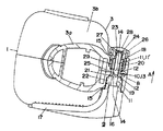
掛止用フック16の回転軸方向において、電池パック取付部3bの幅Wは電池パック2の幅と略一致するように形成しているので、掛止用フック16の回転軸方向の端部位置Qは電池パック2の幅内に納められることとなる(図1参照)。図2には掛止用フック16の端部位置Qを電池パック2の幅内(即ち電池パック取付部3bの幅W内)に納めず例えばΔWだけはみ出させた場合を示しているが、これと比較しても明らかなように、図1に示す本例の可搬式電動工具は掛止用フック16まで含めた全体としてコンパクト化されるとともに、掛止用フック16の装着、未装着によって可搬式電動工具全体の寸法に生じる寸法の差が小さくなって収納ケース等を共用することが容易になる。また、電動工具本体1が落下した場合にも、掛止用フック16が先に地面等に衝突して破損を生じることが回避されるものである。
【0016】
加えて、上記の位置P1は掛止用フック16の非使用時の収納位置であって該収納位置にあるときはハンドル部17の先端部を本体ハウジング3の電池パック取付部3bに押し当てた状態となるようにしている。このように、掛止用フック16の設定可能な角度として、掛止用フック16の先端部が電池パック取付部3bと当接する角度を収納時の角度として備えておくことで、落下等により掛止用フック16が衝撃を受けた場合も軸部18側にだけ負荷が集中するのでなく先端側にも分散されて、掛止用フック16の破損を更に確実に防止することができるようになっている。
【0017】
【発明の効果】
上記のように請求項1記載の発明にあっては、掛止用フックまで含めた全体として可搬式電動工具がコンパクト化されるとともに、掛止用フックの装着、未装着によって可搬式電動工具全体の寸法に生じる寸法の差が小さくなって収納ケース等を共用することが容易になるという効果がある。また、電動工具本体が落下した場合にも、掛止用フックが先に地面等に衝突して破損を生じることが回避されるという効果がある。
【0018】
また、請求項2記載の発明にあっては、請求項1記載の発明の効果に加えて、落下等により掛止用フックが衝撃を受けた場合も軸部側にだけ負荷が集中するのでなく先端側にも分散されるので、掛止用フックの破損を更に確実に防止することができるという効果がある。
【図面の簡単な説明】
【図1】本発明の実施の形態における一例の可搬式電動工具の水平断面図であり、(a)には掛止用フックを収納位置に係止した状態を示し、(b)には(a)との比較対象として掛止用フックを設けなかった状態を示している。
【図2】同上の可搬式電動工具において、仮に掛止用フックを電池パックの幅からはみ出すように接続させた場合の水平断面図であり、(a)には掛止用フックを収納位置に係止した状態を示し、(b)には(a)との比較対象として掛止用フックを設けなかった状態を示している。
【図3】同上の可搬式電動工具における掛止用フックの接続構造を示す水平断面図である。
【図4】同上の可搬式電動工具の一部分解斜視図である。
【図5】同上の可搬式電動工具の全体斜視図である。
【図6】同上の可搬式電動工具における掛止用フックの係止位置を示す説明図である。
【符号の説明】
1 電動工具本体
2 電池パック
3 本体ハウジング
3b 電池パック取付部
4 モータ
16 掛止用フック
18 軸部
Q 端部位置[0001]
BACKGROUND OF THE INVENTION
The present invention relates to a portable power tool having a hook for hooking on an operator's waist belt or the like.
[0002]
[Prior art]
Conventionally, in order to hook the power tool body on the operator's waist belt, etc., the hook for hooking is connected to the main body of the power tool so as to be rotatable around the shaft protruding from the hook for hooking. A portable electric tool has been proposed (see Patent Document 1). However, in this case, the hook for hooking is positioned so as to protrude from the width of the battery pack connected to the main body of the electric power tool, and even if the electric power tool main body is small, the overall size is increased. When the electric power tool body falls, the hook for hooking first hits the ground or the like and is easily damaged. In addition, since the hook for hooking is always supported only on the shaft portion side, the hook is easily damaged even when a load is concentrated on the shaft portion side due to an impact such as dropping.
[0003]
[Patent Document 1]
JP 2002-254358 A [0004]
[Problems to be solved by the invention]
The present invention has been made in view of the above points, and it is an object of the present invention to provide a compact electric tool that prevents the hook for hooking from being damaged even when the electric power tool body falls. is there.
[0005]
[Means for Solving the Problems]
In order to solve the above-mentioned problems, the present invention is to form a wide battery pack mounting portion in a main body housing of a power tool body incorporating a motor, and connect a battery pack as a motor drive source to the battery pack mounting portion. , to said the latching hook consisting of a shape to form the handle portion and the shaft portion projecting from the base portion of which, the left-right direction when the side of connecting the battery pack and the lower the rotational axis In the portable power tool connected to the vicinity of the battery pack mounting portion of the power tool main body so as to be rotatable about the shaft portion, the end position of the hooking hook in the rotational axis direction is within the width of the battery pack. It shall be characterized by being stored in By doing so, the portable power tool as a whole including the hooks for latching can be made compact, and the difference in dimensions caused in the dimensions of the entire portable power tool due to the mounting and non-mounting of the hooks for hooking can be reduced. It becomes small and it becomes easy to share a storage case. In addition, even when the electric power tool body falls, it is avoided that the hook for hooking first collides with the ground or the like to cause damage.
[0006]
Moreover, it is also preferable to provide an angle at which the tip of the hook for hooking comes into contact with the battery pack mounting portion as an angle at which the hook for hooking can be set. In this way, even when the hook for hooking is subjected to an impact due to dropping or the like, the load is not concentrated only on the shaft part side but is also distributed on the tip side, so that the hooking hook is more reliably damaged. Will be prevented.
[0007]
DETAILED DESCRIPTION OF THE INVENTION
Hereinafter, the present invention will be described based on embodiments shown in the accompanying drawings. FIG. 5 shows the entire portable electric tool as an example in the embodiment of the present invention. An example of the portable electric tool is an electric driver that mainly includes an electric tool main body 1 and a
[0008]
As shown in FIGS. 3 and 4, a
[0009]
The
[0010]
In the state in which the
[0011]
In the state where the
[0012]
In order to attach the
[0013]
In the mounting state of the
[0014]
The rotation around the
[0015]
Since the width W of the battery
[0016]
Pressed addition, the position P 1 of the above battery
[0017]
【The invention's effect】
As described above, according to the first aspect of the present invention, the portable electric tool is made compact as a whole including the hook for hooking, and the entire portable electric tool is attached by attaching or not attaching the hook for hooking. Thus, there is an effect that the difference in the size of the size is reduced, and it becomes easy to share the storage case and the like. In addition, even when the electric power tool body falls, it is possible to prevent the hook for hook from colliding with the ground or the like first and causing damage.
[0018]
Further, in the invention according to
[Brief description of the drawings]
FIG. 1 is a horizontal sectional view of an example of a portable power tool according to an embodiment of the present invention. FIG. 1 (a) shows a state in which a hook for locking is locked in a storage position, and FIG. The state which did not provide the hook for latching as a comparison object with a) is shown.
FIG. 2 is a horizontal sectional view of the portable power tool according to the first embodiment when the hook for hooking is connected so as to protrude from the width of the battery pack. FIG. The state which latched is shown, (b) has shown the state which did not provide the hook for latching as a comparison object with (a).
FIG. 3 is a horizontal sectional view showing a connection structure of a hook for latching in the portable electric tool.
FIG. 4 is a partially exploded perspective view of the same portable power tool.
FIG. 5 is an overall perspective view of the portable power tool of the same.
FIG. 6 is an explanatory view showing a locking position of a hook for hooking in the portable electric tool.
[Explanation of symbols]
DESCRIPTION OF SYMBOLS 1 Electric tool
Claims (2)
Priority Applications (4)
| Application Number | Priority Date | Filing Date | Title |
|---|---|---|---|
| JP2002343034A JP3918723B2 (en) | 2002-11-26 | 2002-11-26 | Portable electric tool |
| CNB2003801018892A CN100379527C (en) | 2002-11-26 | 2003-11-25 | Mobile electric tool with hook |
| AU2003284667A AU2003284667A1 (en) | 2002-11-26 | 2003-11-25 | Portable electric tool with hanging hook |
| PCT/JP2003/014984 WO2004048046A1 (en) | 2002-11-26 | 2003-11-25 | Portable electric tool with hanging hook |
Applications Claiming Priority (1)
| Application Number | Priority Date | Filing Date | Title |
|---|---|---|---|
| JP2002343034A JP3918723B2 (en) | 2002-11-26 | 2002-11-26 | Portable electric tool |
Publications (2)
| Publication Number | Publication Date |
|---|---|
| JP2004174647A JP2004174647A (en) | 2004-06-24 |
| JP3918723B2 true JP3918723B2 (en) | 2007-05-23 |
Family
ID=32375911
Family Applications (1)
| Application Number | Title | Priority Date | Filing Date |
|---|---|---|---|
| JP2002343034A Expired - Fee Related JP3918723B2 (en) | 2002-11-26 | 2002-11-26 | Portable electric tool |
Country Status (4)
| Country | Link |
|---|---|
| JP (1) | JP3918723B2 (en) |
| CN (1) | CN100379527C (en) |
| AU (1) | AU2003284667A1 (en) |
| WO (1) | WO2004048046A1 (en) |
Families Citing this family (13)
| Publication number | Priority date | Publication date | Assignee | Title |
|---|---|---|---|---|
| WO2005058556A1 (en) * | 2003-12-17 | 2005-06-30 | David Haynes | Hanging bracket |
| JP4844832B2 (en) * | 2006-11-24 | 2011-12-28 | 日立工機株式会社 | Power tools |
| JP4844831B2 (en) * | 2006-11-24 | 2011-12-28 | 日立工機株式会社 | Power tools |
| JP5379625B2 (en) * | 2009-09-25 | 2013-12-25 | パナソニック株式会社 | Electric tool |
| US9457461B2 (en) * | 2013-08-06 | 2016-10-04 | Robert Bosch Tool Corporation | Dual axis hook assembly for a power tool |
| CN108340015B (en) * | 2017-01-22 | 2020-09-01 | 南京德朔实业有限公司 | Handheld Power Tools |
| US10531724B2 (en) * | 2017-03-29 | 2020-01-14 | Tti (Macao Commercial Offshore) Limited | Belt clip for power tool |
| JP6976827B2 (en) | 2017-11-22 | 2021-12-08 | 株式会社マキタ | Electric tool |
| CN110293524B (en) * | 2018-03-22 | 2022-05-10 | 丰民金属工业股份有限公司 | Nail gun with hook |
| JP7337530B2 (en) * | 2019-04-05 | 2023-09-04 | 株式会社マキタ | power tools and tool holders |
| CN114683218B (en) | 2020-12-29 | 2025-08-29 | 喜利得股份公司 | Hook assembly for power tool |
| DE112023000567T5 (en) | 2022-02-18 | 2025-01-30 | Milwaukee Electric Tool Corporation | POWERED FASTENER DRIVER |
| DE102024112566A1 (en) | 2023-05-05 | 2024-11-07 | Milwaukee Electric Tool Corporation | POWER-OPERATED FASTENER DRIVER |
Family Cites Families (4)
| Publication number | Priority date | Publication date | Assignee | Title |
|---|---|---|---|---|
| JPH0186671U (en) * | 1987-11-27 | 1989-06-08 | ||
| JP3372398B2 (en) * | 1995-06-27 | 2003-02-04 | 松下電工株式会社 | Rotary tool |
| JP3858607B2 (en) * | 2001-02-15 | 2006-12-20 | 日立工機株式会社 | Battery tools |
| JP3553585B2 (en) * | 2001-03-02 | 2004-08-11 | 日立工機株式会社 | Electric tool |
-
2002
- 2002-11-26 JP JP2002343034A patent/JP3918723B2/en not_active Expired - Fee Related
-
2003
- 2003-11-25 CN CNB2003801018892A patent/CN100379527C/en not_active Expired - Fee Related
- 2003-11-25 AU AU2003284667A patent/AU2003284667A1/en not_active Abandoned
- 2003-11-25 WO PCT/JP2003/014984 patent/WO2004048046A1/en not_active Ceased
Also Published As
| Publication number | Publication date |
|---|---|
| CN1705539A (en) | 2005-12-07 |
| AU2003284667A1 (en) | 2004-06-18 |
| WO2004048046A1 (en) | 2004-06-10 |
| JP2004174647A (en) | 2004-06-24 |
| CN100379527C (en) | 2008-04-09 |
Similar Documents
| Publication | Publication Date | Title |
|---|---|---|
| JP3918723B2 (en) | Portable electric tool | |
| CN102950562B (en) | Screw support device and screw tool assembled with screw support device | |
| US6725945B2 (en) | Impact tool with improved operability | |
| JP3553585B2 (en) | Electric tool | |
| US12296443B2 (en) | Battery powered impact wrench | |
| EP1704023A1 (en) | Rotating shaft locking mechanism | |
| CN108626269B (en) | Hub for ratchet gear | |
| US11986928B2 (en) | Pawl mechanism for ratchet tool | |
| JP3900076B2 (en) | Portable electric tool | |
| US4133543A (en) | Chuck key | |
| JP6416664B2 (en) | Rotating hammer tool | |
| US20060060032A1 (en) | Reset gear, method of use, and ratchet wrench utilizing said gear | |
| JP6615298B2 (en) | Power tools | |
| JP2004174646A (en) | Portable power tool | |
| JP2003245876A5 (en) | ||
| JPH11199134A (en) | Take-up device for wiring harness | |
| JP3553589B2 (en) | Portable tools | |
| JP3542257B2 (en) | Auxiliary tool for tightening round nuts with holes and its holder | |
| JP2008062345A (en) | Power tools | |
| JP2001191269A (en) | Mounting structure of hook on power tool | |
| JP4241255B2 (en) | Portable tool hook | |
| JP2987982B2 (en) | Continuous screw tightening machine | |
| JP2003071735A (en) | Tool attaching mechanism for rotary tool | |
| JP2010234504A (en) | Power tool | |
| JPH0587848U (en) | Screw tightening type connector |
Legal Events
| Date | Code | Title | Description |
|---|---|---|---|
| A621 | Written request for application examination |
Free format text: JAPANESE INTERMEDIATE CODE: A621 Effective date: 20050712 |
|
| A131 | Notification of reasons for refusal |
Free format text: JAPANESE INTERMEDIATE CODE: A131 Effective date: 20060822 |
|
| A521 | Written amendment |
Free format text: JAPANESE INTERMEDIATE CODE: A523 Effective date: 20061023 |
|
| A131 | Notification of reasons for refusal |
Free format text: JAPANESE INTERMEDIATE CODE: A131 Effective date: 20061114 |
|
| A521 | Written amendment |
Free format text: JAPANESE INTERMEDIATE CODE: A523 Effective date: 20061226 |
|
| TRDD | Decision of grant or rejection written | ||
| A01 | Written decision to grant a patent or to grant a registration (utility model) |
Free format text: JAPANESE INTERMEDIATE CODE: A01 Effective date: 20070123 |
|
| A61 | First payment of annual fees (during grant procedure) |
Free format text: JAPANESE INTERMEDIATE CODE: A61 Effective date: 20070205 |
|
| FPAY | Renewal fee payment (event date is renewal date of database) |
Free format text: PAYMENT UNTIL: 20100223 Year of fee payment: 3 |
|
| S533 | Written request for registration of change of name |
Free format text: JAPANESE INTERMEDIATE CODE: R313533 |
|
| FPAY | Renewal fee payment (event date is renewal date of database) |
Free format text: PAYMENT UNTIL: 20100223 Year of fee payment: 3 |
|
| R350 | Written notification of registration of transfer |
Free format text: JAPANESE INTERMEDIATE CODE: R350 |
|
| FPAY | Renewal fee payment (event date is renewal date of database) |
Free format text: PAYMENT UNTIL: 20100223 Year of fee payment: 3 |
|
| FPAY | Renewal fee payment (event date is renewal date of database) |
Free format text: PAYMENT UNTIL: 20110223 Year of fee payment: 4 |
|
| FPAY | Renewal fee payment (event date is renewal date of database) |
Free format text: PAYMENT UNTIL: 20120223 Year of fee payment: 5 |
|
| FPAY | Renewal fee payment (event date is renewal date of database) |
Free format text: PAYMENT UNTIL: 20130223 Year of fee payment: 6 |
|
| FPAY | Renewal fee payment (event date is renewal date of database) |
Free format text: PAYMENT UNTIL: 20130223 Year of fee payment: 6 |
|
| FPAY | Renewal fee payment (event date is renewal date of database) |
Free format text: PAYMENT UNTIL: 20140223 Year of fee payment: 7 |
|
| LAPS | Cancellation because of no payment of annual fees |