JP3914012B2 - Endoscope - Google Patents
Endoscope Download PDFInfo
- Publication number
- JP3914012B2 JP3914012B2 JP2001245606A JP2001245606A JP3914012B2 JP 3914012 B2 JP3914012 B2 JP 3914012B2 JP 2001245606 A JP2001245606 A JP 2001245606A JP 2001245606 A JP2001245606 A JP 2001245606A JP 3914012 B2 JP3914012 B2 JP 3914012B2
- Authority
- JP
- Japan
- Prior art keywords
- treatment instrument
- distal end
- treatment
- opening
- channel
- Prior art date
- Legal status (The legal status is an assumption and is not a legal conclusion. Google has not performed a legal analysis and makes no representation as to the accuracy of the status listed.)
- Expired - Fee Related
Links
- 238000011282 treatment Methods 0.000 claims description 209
- 238000003780 insertion Methods 0.000 claims description 67
- 230000037431 insertion Effects 0.000 claims description 67
- 230000002093 peripheral effect Effects 0.000 claims description 13
- 230000003287 optical effect Effects 0.000 claims description 7
- 230000005484 gravity Effects 0.000 claims description 4
- 238000010586 diagram Methods 0.000 description 17
- 210000004877 mucosa Anatomy 0.000 description 16
- 238000005452 bending Methods 0.000 description 9
- 238000013459 approach Methods 0.000 description 6
- 230000003902 lesion Effects 0.000 description 6
- 230000000007 visual effect Effects 0.000 description 6
- 238000002347 injection Methods 0.000 description 5
- 239000007924 injection Substances 0.000 description 5
- XLYOFNOQVPJJNP-UHFFFAOYSA-N water Substances O XLYOFNOQVPJJNP-UHFFFAOYSA-N 0.000 description 5
- 230000000694 effects Effects 0.000 description 4
- 238000005286 illumination Methods 0.000 description 4
- 230000000630 rising effect Effects 0.000 description 3
- 238000012277 endoscopic treatment Methods 0.000 description 2
- 238000003384 imaging method Methods 0.000 description 2
- 238000000034 method Methods 0.000 description 2
- 230000007935 neutral effect Effects 0.000 description 2
- 238000004140 cleaning Methods 0.000 description 1
- 239000000835 fiber Substances 0.000 description 1
- 230000001788 irregular Effects 0.000 description 1
- 239000000463 material Substances 0.000 description 1
- 239000008155 medical solution Substances 0.000 description 1
- 238000012986 modification Methods 0.000 description 1
- 230000004048 modification Effects 0.000 description 1
- 210000004400 mucous membrane Anatomy 0.000 description 1
- 239000002504 physiological saline solution Substances 0.000 description 1
- 239000011435 rock Substances 0.000 description 1
- 239000007787 solid Substances 0.000 description 1
- 238000005507 spraying Methods 0.000 description 1
- 238000004659 sterilization and disinfection Methods 0.000 description 1
- 238000005406 washing Methods 0.000 description 1
- 238000004804 winding Methods 0.000 description 1
Images


Classifications
-
- A—HUMAN NECESSITIES
- A61—MEDICAL OR VETERINARY SCIENCE; HYGIENE
- A61B—DIAGNOSIS; SURGERY; IDENTIFICATION
- A61B1/00—Instruments for performing medical examinations of the interior of cavities or tubes of the body by visual or photographical inspection, e.g. endoscopes; Illuminating arrangements therefor
- A61B1/00064—Constructional details of the endoscope body
- A61B1/00071—Insertion part of the endoscope body
- A61B1/0008—Insertion part of the endoscope body characterised by distal tip features
- A61B1/00098—Deflecting means for inserted tools
Landscapes
- Health & Medical Sciences (AREA)
- Life Sciences & Earth Sciences (AREA)
- Surgery (AREA)
- Biomedical Technology (AREA)
- Medical Informatics (AREA)
- Optics & Photonics (AREA)
- Pathology (AREA)
- Radiology & Medical Imaging (AREA)
- Biophysics (AREA)
- Engineering & Computer Science (AREA)
- Physics & Mathematics (AREA)
- Heart & Thoracic Surgery (AREA)
- Nuclear Medicine, Radiotherapy & Molecular Imaging (AREA)
- Molecular Biology (AREA)
- Animal Behavior & Ethology (AREA)
- General Health & Medical Sciences (AREA)
- Public Health (AREA)
- Veterinary Medicine (AREA)
- Instruments For Viewing The Inside Of Hollow Bodies (AREA)
- Endoscopes (AREA)
Description
【0001】
【発明の属する技術分野】
本発明は、処置具挿通用チャンネルを複数備え、それぞれの処置具挿通用チャンネルのチャンネル開口より突出される処置具を揺動させて各種処置を行える内視鏡に関する。
【0002】
【従来の技術】
従来より、細長の挿入部を体腔内に挿入することにより、体腔内臓器などを観察したり、必要に応じて処置具チャンネル内に挿通した処置具を用いて各種治療処置の行える医療用の内視鏡が広く利用されている。
【0003】
近年、内視鏡に複数の処置具挿通用チャンネルを設け、それぞれの処置具挿通用チャンネルに異なる処置具を挿通して体腔内の病変部位を内視鏡的に切除する等の手技が有用であると広く認知されている。
【0004】
例えば特開2000−37348号公報の処置用内視鏡には、2つの処置具挿通用チャンネルを備えた内視鏡を用い、各処置具挿通用チャンネルに各種処置具を挿通して処置を行う方式が示されている。
【0005】
前記処置用内視鏡では、一方の処置具挿通用チャンネルの先端開口部に、他方の処置具挿通用チャンネルの先端開口部から離れていく方向に作動する鉗子起上装置を設け、この鉗子起上装置が備えられた処置具挿通用チャンネルに挿通される把持用処置具(以下把持鉗子と呼ぶ)と、他方の処置具挿通用チャンネルに挿通された針状電気メスなどの切開用処置具(以下切開具と呼ぶ)とを組み合わせて処置を行う。
【0006】
具体的には病変粘膜部、若しくはその近傍を把持鉗子で把持した後、切開具が挿通される処置具挿通用チャンネルから離れる方向に把持鉗子を移動させ、引っ張られた状態の粘膜部分を切開具で切除することが記載されている。
【0007】
【発明が解決しようとする課題】
しかしながら、前記特開2000−37348号公報の処置用内視鏡では、把持鉗子で引っ張った粘膜部分を切開具の先端で横方向に切除する誘導手段について何ら言及されていない。このため、前記処置用内視鏡の構成では、切開具の先端位置の誘導を、内視鏡の湾曲操作などで行うしか方法がなく、そのように行う場合には、把持鉗子や内視鏡視野までもが湾曲操作に伴って一緒に動いてしまうという不具合が生じる。
【0008】
また、切開具先端の微妙な操作を、湾曲操作で行うことは難しく、切開作業が非常に難しくなるばかりでなく、1回の操作で切除できる範囲が限られてしまうという不具合があった。
【0009】
本発明は上記事情に鑑みてなされたものであり、複数の処置具挿通用チャンネルの先端開口から処置具を突出させて内視鏡的処置を行う際の作業性に優れた内視鏡を提供することを目的にしている。
【0010】
【課題を解決するための手段】
本発明による内視鏡は、体腔内に挿入可能な挿入部と、体腔内を観察像として撮らえる対物光学系を備え、前記挿入部の先端に設けられた先端部本体と、前記挿入部内に配置され、処置具を挿通可能な管路を有する第1の処置具挿通チャンネルと、前記第1の処置具挿通チャンネルに連通され、前記先端部本体で開口する第1のチャンネル開口部と、前記挿入部内に配置され、処置具を挿通可能な管路を有する第2の処置具挿通チャンネルと、前記第2の処置具挿通チャンネルに連通され、前記先端部本体で開口する第2のチャンネル開口部と、前記第2のチャンネル開口部の先端側に設けられ、前記観察像の左右方向に移動可能な揺動台と、前記揺動台に設けられた、前記第2の処置具挿通チャンネルに挿通された前記処置具を挿通する挿通孔であって、前記揺動台の移動に伴って当該挿通された処置具の外周面を当該揺動台の移動方向に押圧する内壁を備えた挿通孔と、前記先端部本体における前記揺動台の前方であって、前記挿通孔より延出した前記処置具先端部の外周下部が重力により当接可能な位置に配設された弓状曲面が形成された縁部と、を具備し、前記挿通孔より延出した前記処置具先端部は、前記揺動台が観察像の左右方向に移動する際、重力により当接した前記弓状曲面上において当該左右方向へ移動するに従い上方向に移動するよう摺動自在に案内されることを特徴とする。
【0011】
【発明の実施の形態】
以下、図面を参照して本発明の実施の形態を説明する。
【0012】
まず、本発明の実施形態の説明に先立って、本発明の参考となる例について説明する。
図1ないし図11は本発明の参考となる例に係り、図1は内視鏡挿入部の先端部の構成を説明する長手方向断面図、図2は先端部を正面から見たときの図、図3は図1の矢印P側から第2処置具揺動台を見たときの図、図4は図1のX−Y線断面図、図5は第2処置具揺動台の外観形状を説明する図、図6は第2処置具揺動台によって揺動される処置具位置と観察視野範囲との関係を説明する図、図7は第2処置具揺動台によって揺動される処置具と開口との位置関係を説明する図、図8はTVモニタに映し出される処置具の画像を説明する図、図9は第2処置具揺動台の作用を示す図、図10は第1処置具揺動台及び第2処置具揺動台の作用を示す図、図11は第1処置具揺動台及び第2処置具揺動台の作用を示す図である。
【0013】
本参考例の内視鏡は観察画像を表示装置の画面上に表示させるタイプのものであり、内視鏡挿入部は通常の内視鏡と同様、先端側から順に、先端部1、湾曲部(不図示)、可撓管部(不図示)を連設し、内視鏡挿入部全体として軟性に構成してある。
【0014】
図1及び図2に示すように前記先端部1には内視鏡先端面を傾斜面2aにした硬質な先端硬性部材2が設けられている。この先端硬性部材2の傾斜面2aには観察光学系11を構成する観察窓3と、照明光学系13を構成する例えば2つの照明窓4と、前記観察窓3に開口を対向させた送気送水ノズル5と、前方側送水口6と、第1処置具挿通用チャンネル7に連通する第1チャンネル開口部8の第1チャンネル開口8aと、第2処置具挿通用チャンネル9に連通する第2チャンネル開口部10の第2チャンネル開口10aとが設けられている。つまり、本参考例の内視鏡は斜視型の内視鏡である。
【0015】
前記先端硬性部材2の第1チャンネル開口部8近傍には第1チャンネル開口8aから導出される図示しない処置具の体腔内突出方向を調整する処置具載置面14aを形成した略平板状で図中上下方向に揺動する第1処置具揺動台14を配置する第1処置具揺動台配置部14Aが形成されている。
【0016】
また、前記第2チャンネル開口部10近傍には第2チャンネル開口10aから導出される図示しない処置具の体腔内突出方向を調整する処置具挿通孔19を形成した略ブロック形状で図中左右方向に揺動する第2処置具揺動台15を配置する第2処置具揺動台配置部15Aが形成されている。
【0017】
そして、前記第1処置具揺動台14の配置位置を、前記第2処置具揺動台15の配置位置よりも基端側で、かつ上方側に設定するとともに、前記第1処置具揺動台14及び第2処置具揺動台15の配置位置を、前記観察窓3の上辺3uより上方側に設定している。本参考例においては、内視鏡が斜視型であるので、傾斜面2aの先端側から順に、観察窓3、第2処置具揺動台15、第1処置具揺動台14が軸方向に配置されている。
【0018】
前記第2処置具揺動台配置部15Aは、内視鏡先端部外径寸法の大径化を図ることなく、前記第2処置具揺動台15の揺動範囲を大きくとることができるように、先端部1の最大径部分である直径近傍に設けてある。
【0019】
なお、前記観察光学系11は斜視型に限定されるものではなく、直視、或いは側視であってもよく、前記観察窓3も辺を持たない丸型でもよい。また、前記観察光学系11の結像位置には撮像素子12が配設されている。さらに、前記照明窓4の基端面には照明光を導光する図示しないライトガイドファイバーの先端面が臨まれている。又、前記送気送水ノズル5は、前記観察窓3の表面に洗滌水を噴き付けて洗滌する送水ノズルと、体腔内に空気等の気体を送り込むノズルとを兼用している。さらに、前記先端硬性部材2の基端部には湾曲部を構成する第1湾曲駒37が連結され、この第1湾曲駒37の外側には湾曲ゴム38が被覆されている。この湾曲ゴム38の先端部は、糸巻き接着によって前記先端硬性部材2に水密に固定されている。そして、内視鏡挿入部の基端側に設けられた操作部(不図示)の図示しない操作ノブを適宜操作することによって湾曲部を湾曲させて、先端硬性部材2を上下左右に移動させることができるようになっている。
【0020】
図1ないし図8を参照して第1処置具揺動台14及び第2処置具揺動台15の構成及びその配置位置関係を説明する。なお、図1中の矢印Q方向は、術者が観察するTVモニタの画面上方向である。
まず、図1ないし図3を参照して第1処置具揺動台14について説明する。
【0021】
前記第1処置具揺動台14は、この第1処置具揺動台14の基端側に配置される第1の軸16により、前記先端硬性部材2に対して上下方向に回動自在な状態にしている。また、この第1処置具揺動台14の先端側には第1ワイヤ端末部材17が回動自在に設けられており、この第1ワイヤ端末部材17に第1操作ワイヤ18の先端部が連結固定されている。この第1操作ワイヤ18の基端部は、内視鏡挿入部内を挿通して図示しない第1の揺動台操作機構に連結固定されている。
【0022】
したがって、第1の揺動台操作機構によって前記第1操作ワイヤ18を進退させることによって、第1処置具揺動台14が第1の軸16を中心に実線に示す倒置位置と二点鎖線で示す最大起上位置との間を回動する。
【0023】
なお、前記第1処置具揺動台14の回転規制は、先端硬性部材2に設けられている当接面2bと、第1処置具揺動台14の倒置面14b、起上面14cとの突き当てで行う。すなわち、倒置位置で先端硬性部材2の当接面2bと第1処置具揺動台14の倒置面14b面とが突き当たり、最大起上位置で先端硬性部材2の当接面2bと第1処置具揺動台14の起上面14cとが突き当たる構成になっている。
【0024】
次に、図1ないし図8を参照して第2処置具揺動台15の構成及びその配置位置を説明する。
前記第2処置具揺動台15は、図1及び図4に示すようにこの第2処置具揺動台15から突設する第2の軸22及び第3の軸23を前記先端硬性部材2の延出部30及び先端硬性部材2の所定位置に配置して、この軸22,23を中心に第2処置具揺動台15が先端硬性部材2の左右方向に回動自在な状態にしている。
【0025】
前記第2処置具揺動台15は、処置具挿通孔19の開口19aが形成された傾斜面20aを有する台本体部20と、前記第2処置具挿通用チャンネル9を介して導入される第2処置具を前記処置具挿通孔19に導く一対の処置具誘導壁部26と、第2処置具揺動台15を左右に揺動させるための操作ワイヤ24,25が接続される前記傾斜面20aから両側部に突出した一対の凸部20b、20cとで構成されている。
【0026】
前記台本体部20の上面中央部には第2の軸22を配設する第1回転軸配置穴21aが形成され、この回転軸用孔21と同軸上の下面中央部には第3の軸23を配設する第2回転軸配置穴21bが形成されている。
【0027】
前記凸部20bに回動自在に設けられたワイヤ端末部材32には第2操作ワイヤ24の先端部が連結固定され、前記凸部20cに回動自在に設けられたワイヤ端末部材33には第3操作ワイヤ25の先端部が連結固定されている。これら第2の操作ワイヤ24及び第3の操作ワイヤ25の基端部は、挿入部内を挿通して図示しない第2の揺動台操作機構に連結固定されている。
【0028】
したがって、この第2の揺動台操作機構によって前記操作ワイヤ24,25を適宜進退させることによって、第2処置具揺動台15が第2の軸22及び第3の軸23を中心に左右方向に回動する。
【0029】
図2に示すように前記処置具挿通孔19の開口19aの左右方向に対する開口中心線28と、前記第2チャンネル開口部10の左右方向に対するチャンネル中心線29と、前記観察窓3の左右方向に対する視野中心線27とを略同一面に位置するように設けている。また更に、開口中心線28、視野中心線27、チャンネル中心線29を、先端部の左右方向中心線の近傍の略同一面に位置するように設定してもよい。
【0030】
なお、前記第2処置具揺動台15の回転規制は、先端硬性部材2に周状に形成した少なくとも1つ以上のストッパー凹部31の端部31a、31bとワイヤ端末部材32、33との突き当てで行う。すなわち、ストッパー凹部31の所定位置に形成した端部31aとワイヤ端末部材32とを突き当てるとともに、ストッパー凹部31の所定位置に形成した端部31bとワイヤ端末部材33とを突き当てる構成にして所定の回転角を設定している。
【0031】
前記ワイヤ24,25が牽引されていない中立状態のとき、図6及び図7に示すように処置具挿通孔19の開口19aから突出している処置具44の位置は、実線に示す位置にある。そして、それぞれのワイヤ24,25を牽引操作して図7に示すように開口19aの向きを最も右側、又は最も左側に向けるように回動させると前記開口19aは二点鎖線に示す位置に移動する。このとき、開口底部49に位置する処置具44は先端構成部2の開口縁部50から離れた状態で回動する。
【0032】
前記開口19aから処置具44を突出させるとき、先端硬性部材2の先端面である傾斜面2aから、粘膜切除作業を行うに当たって、処置具操作上、近からず遠からずの一番操作し易いとされる所定量である、例えば約15mm突出させた状態にする。この状態で、前記第2の操作ワイヤ24及び第3の操作ワイヤ25を操作して前記第2処置具揺動台15を回動させると、図6に示すように処置具44の先端部が観察窓3の左右観察視野範囲を越えることなく移動する。
【0033】
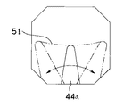
このとき、図8に示すように内視鏡画像上に表示される処置具画像44aは、実線に示す中立状態位置から処置具先端が2点鎖線に示す先端軌跡51を描いて内視鏡画像範囲内を実線矢印に示すように左右両方向に回動移動する。
【0034】
なお、前記処置具44の内視鏡画像上での先端軌跡51は、内視鏡画像の左右周辺部に近づくにしたがって上側にいくようにカーブしている。これは、前記図6に示すように観察窓3からの距離L1,L2,L3の間の関係が
L2(L3)<L1 であるためである。
【0035】
なお、前記処置具の処置具画像44aが画面の略上方側から突出したように映し出されるのは上述したように第2処置具揺動台15の配置位置を観察窓3の上辺3uより上方側に設定したためである。
【0036】
また、前記処置具誘導壁26の内面には、少なくとも前記第2処置具揺動台15の左右方向最大回動時、処置具44を回転方向とは反対方向に押圧する作用点又は作用稜線39が形成してある。このため、処置具44を左右に大きく振ったとき、この処置具44が開口19a内周面と作用稜線39との2点で支持されるので、処置具44を確実にホールドして作業を行える。
【0037】
さらに、前記処置具挿通孔19の開口19aを、左右方向に対して上下方向に長い長円形で形成して、図1に示すように、処置具挿通孔19の開口19aから突出する処置具44と開口19aとの間の左右方向及び上下方向のクリアランスは、揺動方向である左右方向クリアランスの和(X1+X2)よりも、上下方向クリアランス(Y)を、大きく、若しくは同寸法になるように設定している。つまり、YとX1,X2との間に、 Y≧X1+X2 の関係を設定して、この第2処置具揺動台15によって揺動操作される処置具44の振れ量を少なくして微妙な作業を可能にしている。
【0038】
なお、図4に示すように第2の操作ワイヤ24は、第1処置具揺動台14のすぐ真下を通って挿入部内に導かれている。
【0039】
また、図5では台本体部20の傾斜面20a内で外周が連続する開口19aを示しているが、この開口19aを大きめに形成して傾斜面20a内で開口19aの外周の一部が不連続になる形状であってもよい。つまり、開口19aの形状について特に限定はしない。
【0040】
さらに、第1処置具揺動台14が配置される第1処置具揺動台配置部14Aに、この第1処置具揺動台14を起上させたとき、第2処置具揺動台配置部15Aに連通する開口部を形成して、内視鏡の洗滌・消毒性を向上させている。
【0041】
又、前記第2処置具揺動台15を回動させたとき、操作ワイヤ24,25が処置具誘導壁26に接触することを防止するように前記処置具誘導壁26の高さ寸法が設定されている。
【0042】
また、前記第1の揺動台操作機構及び第2の揺動台操作機構の位置関係及び機構、或いは前記第1処置具挿通用チャンネル7と前記第2処置具挿通用チャンネル9のチャンネル内径寸法及びチャンネルの材質、硬さ等についても特に限定されるものではない。
【0043】
上述のように構成した内視鏡の作用を説明する。
まず、図9に示すように内視鏡挿入部40の先端部1に設けられている観察窓3を病変粘膜に対向させる。そして、病変粘膜に対して内視鏡的観察を行うとともに、例えば第2処置具挿通用チャンネル9を介して処置具である注射針42を体腔内に導入する。ここで、注射針42を病変粘膜に対向させるために第2処置具揺動台15を揺動させて注射針42を病変粘膜の所定部位に対向させ、注射針42を矢印aに示すように目的部位に進め、病変粘膜の下層に生理食塩水などの薬液を注入する。すると、病変粘膜を含む粘膜層を隆起する。
【0044】
次に、図10に示すように第1処置具挿通用チャンネル7を介して処置具である把持鉗子43を体腔内に導入する。ここで、この把持鉗子43を、隆起した粘膜層に対向させるため、第1処置具揺動台14を揺動する。そして、把持鉗子43を粘膜層の所定部位に対向させたなら、この把持鉗子43を押し進めて隆起した病変粘膜を含む粘膜層を把持する。一方、前記第2処置具挿通用チャンネル9に注射針42の代わりに処置具である切開具44を挿入し、この切開具44を病変粘膜近傍に配置する。
【0045】
次いで、第1処置具揺動台14を揺動させて把持鉗子43を矢印b方向に起上させていく。すると、把持鉗子43によって把持されていた病変粘膜を含む粘膜層が引っ張り上げられた状態になる。
【0046】
ここで、図11に示すように切開具44を所定量突出させた後、第2処置具揺動台15を矢印c、d方向に揺動させて、隆起した粘膜下層部を切開具44で切除していく。このとき、第1処置具揺動台14が第2処置具揺動台15の上方側に配置されているので、病変粘膜を吊り上げた状態で、観察窓3を通して切開面側の状況、例えば切開具44先端の深さに注意を払いながら、病変粘膜の根元部を切除する切除作業を速やかに行える。このとき処置具先端は、左右方向を広範囲に移動することができる。
【0047】
また、切開具44の先端が先端面から所定量、突出させることにより、切開具44の先端を左右方向に移動させたとき、内視鏡画像範囲を絶対に超えることがない構成であるので、常に、処置具44の先端位置を確認しながら切開作業を進めることができる。
【0048】
さらに、切開具44の先端軌跡51が、内視鏡画像の左右周辺部側に近づくにしたがって上方向にカーブするため、内視鏡画像の左右周辺部でたとえ切開具44の処置具画像44aが揺動した場合でも刃先位置が処置部位に切り込むことが防止される。
【0049】
又、開口底部49に位置する切開具44が少なくとも揺動範囲において開口縁部50から離れた状態で移動するのでこの切開具44が回転されることはない。
【0050】
以上説明したように当該内視鏡によれば、内視鏡とそれに組み合わせられる処置具とを用いれば、広範囲な病変部位に対して確実かつ容易に一括切除が可能となり、かつ操作も容易となることから、確実かつ迅速な手術が可能となり、術者と患者の両方の負担を低減しながら行うことができる。
【0051】
次に、本発明の実施形態について説明する。
図12ないし図15は本発明の実施形態にかかり、図12は内視鏡先端部を正面から見たときの図、図13はこの内視鏡先端部の長手方向断面図、図14は処置具挿通孔の開口とこの開口から突出する処置具の揺動状態を説明する図、図15はTVモニタに映し出される処置具の画像を説明する図である。
【0052】
本実施形態においては図12に示すように絶縁カバー52を含む先端構成部2の開口縁部50の形状を弓状曲面で形成している。そして、第2処置具揺動台15を揺動させたとき、開口19aの開口底部49の揺動軌跡が開口縁部50の下側を通る構成にしている。
【0053】
つまり、図13に示すように開口底部49の位置は、開口縁部50より寸法hだけ落とし込んで形成してある。このことにより、前記第2処置具揺動台15を揺動させたとき、図14に示すように開口19a位置は、前記参考例と同様に左右方向に揺動するが、この開口19aから突出している切開具44は開口縁部50の弓状曲面上を移動する。
【0054】
このことにより、例えば前記処置具44を観察窓3の設けられた先端面36から所定量突出させて、第2処置具揺動台15を揺動させたとき、内視鏡画像上には図15に示すように前記参考例の先端軌跡51よりも左右周辺部で上側になる大きなカーブの先端軌跡51aが示される。このとき、前記参考例と同様、処置具44の先端が左右方向の内視鏡画像範囲を絶対に超えないように設定されている。その他の構成は前記参考例と同様であり、同部材には同符合を付して説明を省略する。
【0055】
このように、処置具を開口縁部の弓状曲面に沿わせて移動させることにより、内視鏡画像上に表示される処置具の先端軌跡が、内視鏡画像の左右周辺部側に近づくにしたがって視野上方向に大きくカーブしているので、この左右周辺部で切開具が揺動しても、刃先先端が処置部位に切り込むことをより確実に防止することができる。
【0056】
また、処置具の先端軌跡を内視鏡画像の左右周辺部に近づくにしたがって上方側に大きくカーブさせたことにより、前記参考例よりも左右方向の切開幅を狭くすることができる。
【0057】
さらに、処置具は、回転させて左右に揺動されるためきれいに切ることができる。
【0058】
なお、本図の構成では第2処置具揺動台15の揺動範囲全域において、前記開口底部49の位置が開口縁部50より下側を通る構成にしているが、例えば観察窓3の中心近傍で開口底部49と開口縁部50との高さを略同一に構成するようにしてもよい。
【0059】
また、先端部1の先端面36の形状を平面形状ではなく、図に示すようにな凹状曲面形状等の異形形状にしてもよい。
さらに、前記第2処置具揺動台15の揺動範囲を画面中央から左右両振りに構成する代わりに、図16の第2処置具揺動台の内視鏡画像に対する揺動範囲を説明する図に示すように画面中央からどちらか一方向にだけ揺動させる構成等にしてもよい。
【0060】
又、図17の第2処置具揺動台の観察窓に対する配置位置を示す図のように第2処置具揺動台15の配置位置を観察窓3の下辺3dよりも下方側に設定するようにしてもよい。しかし、このとき、開口底部49と開口縁部50との位置関係が図に示す通りであると、図18に示すように前記処置具44の処置具画像44aが画面の略下方側から突出するとともに処置具44の先端軌跡51bが内視鏡画像の左右周辺部に近づくにしたがって下方側にカーブしてしまう。
【0061】
そこで、図19の処置具挿通孔の開口とこの開口から突出する処置具の揺動状態を説明する図に示すように開口縁部50aを弓形曲面に形成して第2処置具揺動台15の揺動全域において、開口19aの開口底部49が開口縁部50の下側を通る位置関係にする。このことにより、図20のTVモニタに映し出される処置具の画像を説明する図に示すように内視鏡画像上には切開具44の先端が左右方向の内視鏡画像範囲を絶対に超えることなく、処置具の先端軌跡51cが前記参考例及び本実施形態と同様、内視鏡画像の左右周辺部に近づくにしたがって上方向にカーブさせられる。このことによって、上述した本実施形態と同様の作用及び効果を得ることができる。
【0062】
さらにまた、観察光学系は斜視型に限定されるものではなく、図21の第1処置具揺動台及び第2処置具揺動台を備えた直視型の内視鏡の図に示すように直視型や側視型で構成するようにしてもよい。また、上述した観察窓は丸型であってもよい。
【0063】
なお、本発明は、以上述べた実施形態のみに限定されるものではなく、発明の要旨を逸脱しない範囲で種々変形実施可能である。
【0064】
【発明の効果】
以上説明したように本発明によれば、複数の処置具挿通用チャンネルの先端開口から処置具を突出させて内視鏡的処置を行う際の作業性に優れた内視鏡を提供することができる。
【図面の簡単な説明】
【図1】図1ないし図11は本発明の参考例に係り、図1は内視鏡挿入部の先端部の構成を説明する長手方向断面図
【図2】先端部を正面から見たときの図
【図3】図1の矢印P側から第2処置具揺動台を見たときの図
【図4】図1のX−Y線断面図
【図5】第2処置具揺動台の外観形状を説明する図
【図6】第2処置具揺動台によって揺動される処置具位置と観察視野範囲との関係を説明する図
【図7】第2処置具揺動台によって揺動される処置具と開口との位置関係を説明する図
【図8】TVモニタに映し出される処置具の画像を説明する図
【図9】第2処置具揺動台の作用を示す図
【図10】第1処置具揺動台及び第2処置具揺動台の作用を示す図
【図11】第1処置具揺動台及び第2処置具揺動台の作用を示す図
【図12】図12ないし図15は本発明の実施形態にかかり、図12は内視鏡先端部を正面から見たときの図
【図13】この内視鏡先端部の長手方向断面図
【図14】処置具挿通孔の開口とこの開口から突出する処置具の揺動状態を説明する図
【図15】TVモニタに映し出される処置具の画像を説明する図
【図16】第2処置具揺動台の内視鏡画像に対する揺動範囲を説明する図
【図17】第2処置具揺動台の観察窓に対する配置位置を示す図
【図18】図17の第2処置具揺動台を揺動させたとき、TVモニタに映し出される処置具の画像を説明する図
【図19】処置具挿通孔の開口とこの開口から突出する処置具の揺動状態を説明する図
【図20】TVモニタに映し出される処置具の画像を説明する図
【図21】第1処置具揺動台及び第2処置具揺動台を備えた直視型の内視鏡を説明する図
【符号の説明】
1…先端部
2…先端硬性部材
2a…傾斜面
3…観察窓
15…第2処置具揺動台
49…開口底部
50…開口縁部[0001]
BACKGROUND OF THE INVENTION
The present invention relates to an endoscope that includes a plurality of treatment instrument insertion channels and can perform various treatments by swinging a treatment instrument protruding from a channel opening of each treatment instrument insertion channel.
[0002]
[Prior art]
Conventionally, by inserting a long and thin insertion portion into a body cavity, the inside of a body cavity can be observed, and various medical treatments can be performed using a treatment instrument inserted into a treatment instrument channel as necessary. Endoscopes are widely used.
[0003]
In recent years, a technique has been useful in which a plurality of treatment instrument insertion channels are provided in an endoscope, and a different treatment instrument is inserted into each treatment instrument insertion channel to endoscopically remove a lesion site in a body cavity. Widely recognized.
[0004]
For example, the treatment endoscope disclosed in Japanese Patent Laid-Open No. 2000-37348 uses an endoscope having two treatment instrument insertion channels, and performs treatment by inserting various treatment instruments into each treatment instrument insertion channel. The scheme is shown.
[0005]
In the treatment endoscope, a forceps raising device that operates in a direction away from the distal end opening of the other treatment instrument insertion channel is provided at the distal end opening of one treatment instrument insertion channel. A treatment instrument for grasping (hereinafter referred to as grasping forceps) inserted into a treatment instrument insertion channel provided with the upper device, and an incision treatment instrument such as a needle-shaped electric knife inserted into the other treatment instrument insertion channel ( The treatment is performed in combination with an incision tool).
[0006]
Specifically, after grasping the lesion mucosa or its vicinity with grasping forceps, the grasping forceps are moved in a direction away from the treatment instrument insertion channel through which the incision tool is inserted, and the pulled mucosa portion is incised. It is described that excision.
[0007]
[Problems to be solved by the invention]
However, in the treatment endoscope disclosed in Japanese Patent Laid-Open No. 2000-37348, there is no mention of a guiding means for excising the mucosal portion pulled by the grasping forceps in the lateral direction at the distal end of the cutting tool. For this reason, in the configuration of the treatment endoscope, there is only a method for guiding the distal end position of the incision tool by a bending operation of the endoscope. In such a case, a grasping forceps or an endoscope is used. There is a problem that even the visual field moves together with the bending operation.
[0008]
In addition, it is difficult to perform delicate operations on the distal end of the incision tool by a bending operation, so that not only the incision operation becomes very difficult, but also the range that can be excised by a single operation is limited.
[0009]
The present invention has been made in view of the above circumstances, and provides an endoscope excellent in workability when performing a endoscopic treatment by projecting a treatment tool from the distal end openings of a plurality of treatment tool insertion channels. The purpose is to do.
[0010]
[Means for Solving the Problems]
An endoscope according to the present invention includes an insertion portion that can be inserted into a body cavity, an objective optical system that captures the inside of the body cavity as an observation image, a distal end portion body provided at the distal end of the insertion portion, and the insertion portion. A first treatment instrument insertion channel disposed and having a conduit through which the treatment instrument can be inserted; a first channel opening that communicates with the first treatment instrument insertion channel and opens at the distal end body; A second treatment instrument insertion channel disposed in the insertion section and having a conduit through which the treatment instrument can be inserted; and a second channel opening communicating with the second treatment instrument insertion channel and opening at the distal end portion main body And an oscillating base provided on the distal end side of the second channel opening and movable in the left-right direction of the observation image, and inserted into the second treatment instrument insertion channel provided on the oscillating base. Inserting the treatment tool An insertion hole provided with an inner wall that presses the outer peripheral surface of the inserted treatment instrument in the movement direction of the rocking table in accordance with the movement of the rocking table, and the rocking in the tip body An edge portion formed with an arcuate curved surface disposed at a position where the outer peripheral lower portion of the distal end portion of the treatment tool extending from the insertion hole can come into contact with gravity, in front of the table, The distal end portion of the treatment instrument extending from the insertion hole moves upward as the oscillating base moves in the left-right direction on the arcuate curved surface abutted by gravity when the oscillating base moves in the left-right direction of the observation image. It is slidably guided so as to move.
[0011]
DETAILED DESCRIPTION OF THE INVENTION
Embodiments of the present invention will be described below with reference to the drawings.
[0012]
First, prior to the description of the embodiment of the present invention, an example serving as a reference of the present invention will be described.
1 to 11 show the present invention.Example for reference1 is a longitudinal sectional view for explaining the configuration of the distal end portion of the endoscope insertion portion, FIG. 2 is a view when the distal end portion is viewed from the front, and FIG. 3 is a second view from the arrow P side in FIG. FIG. 4 is a cross-sectional view taken along the line XY of FIG. 1, FIG. 5 is a diagram for explaining the external shape of the second treatment instrument swinging table, and FIG. FIG. 7 is a diagram for explaining the relationship between the position of the treatment instrument swung by the swing table and the observation visual field range, and FIG. 7 is a diagram for explaining the positional relationship between the treatment tool swung by the second treatment tool swing table and the opening. FIG. 8 is a diagram for explaining an image of the treatment instrument displayed on the TV monitor, FIG. 9 is a diagram illustrating the operation of the second treatment instrument swinging table, and FIG. 10 is a diagram illustrating the first treatment instrument swinging table and the second treatment instrument swinging. The figure which shows the effect | action of a moving table, FIG. 11 is a figure which shows the effect | action of a 1st treatment tool rocking | fluctuation table and a 2nd treatment tool rocking | fluctuation table.
[0013]
BookReference exampleThe endoscope of this type is a type that displays an observation image on the screen of a display device, and the endoscope insertion part is a distal end part 1 and a bending part (not shown) in order from the distal end side in the same manner as a normal endoscope. ), A flexible tube portion (not shown) is continuously provided, and the entire endoscope insertion portion is configured to be flexible.
[0014]
As shown in FIGS. 1 and 2, the distal end portion 1 is provided with a rigid distal end
[0015]
In the vicinity of the first channel opening 8 of the distal end
[0016]
Further, in the vicinity of the second channel opening 10, a treatment
[0017]
Then, the arrangement position of the first treatment instrument rocking table 14 is set on the proximal side and above the arrangement position of the second treatment tool rocking table 15, and the first treatment tool rocking table 14 is swung. The arrangement positions of the table 14 and the second treatment instrument swing table 15 are set above the upper side 3u of the
[0018]
The second treatment instrument oscillating
[0019]
The observation
[0020]
With reference to FIG. 1 thru | or FIG. 8, the structure and arrangement | positioning positional relationship of the 1st treatment tool rocking |
First, the first treatment
[0021]
The first treatment instrument swinging table 14 is rotatable up and down with respect to the distal end
[0022]
Therefore, by moving the
[0023]
It should be noted that the rotation restriction of the first treatment instrument swinging table 14 is that the
[0024]
Next, the configuration and arrangement position of the second treatment
As shown in FIGS. 1 and 4, the second treatment instrument swinging table 15 is provided with a
[0025]
The second treatment instrument swinging table 15 is introduced through a table
[0026]
A first rotating
[0027]
The distal end portion of the
[0028]
Therefore, the second treatment instrument swinging table 15 is moved in the left-right direction around the
[0029]
As shown in FIG. 2, the opening center line 28 with respect to the left-right direction of the opening 19 a of the treatment
[0030]
It should be noted that the rotation restriction of the second treatment
[0031]
When the
[0032]
When the
[0033]
At this time, as shown in FIG. 8, the
[0034]
Note that the
This is because L2 (L3) <L1.
[0035]
Note that the
[0036]
Further, on the inner surface of the treatment
[0037]
Further, the
[0038]
As shown in FIG. 4, the
[0039]
Further, FIG. 5 shows the
[0040]
Further, when the first treatment instrument swinging table 14 is raised in the first treatment instrument swinging
[0041]
Further, the height dimension of the treatment
[0042]
Further, the positional relationship and mechanism of the first swing table operating mechanism and the second swing table operating mechanism, or the channel inner diameter dimensions of the first treatment
[0043]
The operation of the endoscope configured as described above will be described.
First, as shown in FIG. 9, the
[0044]
Next, as shown in FIG. 10, the grasping
[0045]
Next, the first treatment
[0046]
Here, as shown in FIG. 11, after the
[0047]
In addition, since the distal end of the
[0048]
Furthermore, since the
[0049]
Further, since the
[0050]
As explained aboveConcernedAccording to an endoscope, if an endoscope and a treatment tool combined therewith are used, it is possible to reliably and easily perform a batch excision of a wide range of lesion sites, and an operation becomes easy. Can be performed while reducing the burden on both the operator and the patient.
[0051]
Next, an embodiment of the present invention will be described.
12 to 15 areEmbodiment of the present invention12 is a view of the endoscope distal end portion as viewed from the front, FIG. 13 is a longitudinal sectional view of the endoscope distal end portion, and FIG. 14 is an opening of the treatment instrument insertion hole and protrudes from the opening. FIG. 15 is a diagram for explaining a swinging state of the treatment instrument, and FIG. 15 is a diagram for explaining an image of the treatment instrument displayed on the TV monitor.
[0052]
In this embodiment, as shown in FIG. 12, the shape of the opening
[0053]
That is, as shown in FIG. 13, the position of the opening
[0054]
Thus, for example, when the
[0055]
In this way, by moving the treatment tool along the arcuate curved surface of the opening edge, the tip trajectory of the treatment tool displayed on the endoscopic image approaches the left and right peripheral side of the endoscopic image. Therefore, even if the cutting tool swings in the left and right peripheral parts, the cutting edge tip can be more reliably prevented from being cut into the treatment site.
[0056]
In addition, by making the tip trajectory of the treatment instrument curve largely upward as it approaches the left and right peripheral portions of the endoscopic image,Reference exampleThe incision width in the left-right direction can be made narrower.
[0057]
Furthermore, since the treatment instrument is rotated and swung left and right, it can be cut cleanly.
[0058]
In the configuration of this figure, the position of the opening bottom 49 passes below the opening
[0059]
Further, the shape of the
Furthermore, instead of configuring the swing range of the second treatment
[0060]
Also, the arrangement position of the second treatment instrument rocking table 15 is set to be lower than the
[0061]
Therefore, as shown in the drawing for explaining the opening of the treatment instrument insertion hole and the swinging state of the treatment instrument protruding from the opening in FIG. 19, the opening edge portion 50a is formed in an arcuate curved surface to form the second treatment instrument swinging table 15. The opening
[0062]
Furthermore, the observation optical system is not limited to the perspective type, as shown in the view of the direct-viewing type endoscope provided with the first treatment instrument swinging table and the second treatment tool swinging table in FIG. A direct-view type or a side-view type may be used. Further, the observation window described above may be round.
[0063]
It should be noted that the present invention is not limited to the embodiments described above, and various modifications can be made without departing from the spirit of the invention.
[0064]
【The invention's effect】
As described above, according to the present invention, it is possible to provide an endoscope excellent in workability when performing an endoscopic treatment by projecting a treatment tool from the distal end openings of a plurality of treatment tool insertion channels. it can.
[Brief description of the drawings]
FIG. 1 to FIG.Reference exampleFIG. 1 is a longitudinal sectional view for explaining the configuration of the distal end portion of the endoscope insertion portion.
FIG. 2 is a view when the front end is viewed from the front.
FIG. 3 is a view when the second treatment instrument swinging table is viewed from the arrow P side in FIG. 1;
4 is a cross-sectional view taken along line XY in FIG.
FIG. 5 is a diagram for explaining the external shape of a second treatment instrument swinging table;
FIG. 6 is a view for explaining the relationship between the treatment instrument position swung by the second treatment tool swinging table and the observation visual field range;
FIG. 7 is a view for explaining the positional relationship between a treatment tool swung by a second treatment tool rocking table and an opening;
FIG. 8 is a diagram for explaining an image of a treatment tool displayed on a TV monitor;
FIG. 9 is a view showing the operation of the second treatment instrument swinging table.
FIG. 10 is a diagram showing the operation of the first treatment instrument swing table and the second treatment instrument swing table.
FIG. 11 is a diagram showing the operation of the first treatment instrument swing table and the second treatment instrument swing table.
FIG. 12 to FIG.Embodiment of the present inventionFIG. 12 is a diagram when the distal end portion of the endoscope is viewed from the front.
FIG. 13 is a longitudinal sectional view of the endoscope distal end portion.
FIG. 14 is a view for explaining an opening of the treatment instrument insertion hole and a swinging state of the treatment instrument protruding from the opening;
FIG. 15 is a diagram for explaining an image of a treatment tool displayed on a TV monitor;
FIG. 16 is a view for explaining the swing range of the second treatment instrument swing table with respect to the endoscopic image;
FIG. 17 is a diagram showing an arrangement position of the second treatment instrument swing table with respect to the observation window.
18 is a view for explaining an image of a treatment instrument displayed on a TV monitor when the second treatment instrument swinging table of FIG. 17 is swung.
FIG. 19 is a view for explaining the opening of the treatment instrument insertion hole and the swinging state of the treatment instrument protruding from the opening;
FIG. 20 is a diagram for explaining an image of a treatment tool displayed on a TV monitor.
FIG. 21 is a diagram for explaining a direct-viewing type endoscope provided with a first treatment instrument rocking table and a second treatment tool rocking table.
[Explanation of symbols]
1 ... tip
2. Tip hard member
2a ... Inclined surface
3 ... Observation window
15 ... Second treatment instrument swing table
49 ... Opening bottom
50 ... Opening edge
Claims (1)
体腔内を観察像として撮らえる対物光学系を備え、前記挿入部の先端に設けられた先端部本体と、
前記挿入部内に配置され、処置具を挿通可能な管路を有する第1の処置具挿通チャンネルと、
前記第1の処置具挿通チャンネルに連通され、前記先端部本体で開口する第1のチャンネル開口部と、
前記挿入部内に配置され、処置具を挿通可能な管路を有する第2の処置具挿通チャンネルと、
前記第2の処置具挿通チャンネルに連通され、前記先端部本体で開口する第2のチャンネル開口部と、
前記第2のチャンネル開口部の先端側に設けられ、前記観察像の左右方向に移動可能な揺動台と、
前記揺動台に設けられた、前記第2の処置具挿通チャンネルに挿通された前記処置具を挿通する挿通孔であって、前記揺動台の移動に伴って当該挿通された処置具の外周面を当該揺動台の移動方向に押圧する内壁を備えた挿通孔と、
前記先端部本体における前記揺動台の前方であって、前記挿通孔より延出した前記処置具先端部の外周下部が重力により当接可能な位置に配設された弓状曲面が形成された縁部と、
を具備し、
前記挿通孔より延出した前記処置具先端部は、前記揺動台が観察像の左右方向に移動する際、重力により当接した前記弓状曲面上において当該左右方向へ移動するに従い上方向に移動するよう摺動自在に案内されることを特徴とする内視鏡。An insertion part that can be inserted into a body cavity;
Provided with an objective optical system that captures the inside of the body cavity as an observation image, a distal end portion body provided at the distal end of the insertion portion,
A first treatment instrument insertion channel disposed in the insertion portion and having a conduit through which the treatment instrument can be inserted;
A first channel opening that communicates with the first treatment instrument insertion channel and opens at the tip body;
A second treatment instrument insertion channel disposed in the insertion portion and having a conduit through which the treatment instrument can be inserted;
A second channel opening that communicates with the second treatment instrument insertion channel and opens at the tip body;
An oscillating base provided on the distal end side of the second channel opening and movable in the left-right direction of the observation image;
An insertion hole provided in the oscillating table for inserting the treatment instrument inserted into the second treatment instrument insertion channel, and an outer periphery of the treatment instrument inserted as the oscillating table moves. An insertion hole provided with an inner wall that presses the surface in the moving direction of the swing table,
An arcuate curved surface is formed in front of the oscillating base in the distal end portion main body and disposed at a position where the outer peripheral lower portion of the distal end portion of the treatment instrument extending from the insertion hole can come into contact with gravity. The edge,
Comprising
The distal end portion of the treatment instrument extending from the insertion hole moves upward as the oscillating base moves in the left-right direction on the arcuate curved surface abutted by gravity when the swing table moves in the left-right direction of the observation image. An endoscope characterized by being slidably guided so as to move.
Priority Applications (2)
| Application Number | Priority Date | Filing Date | Title |
|---|---|---|---|
| JP2001245606A JP3914012B2 (en) | 2001-08-13 | 2001-08-13 | Endoscope |
| US10/200,631 US6824509B2 (en) | 2001-07-23 | 2002-07-22 | Endoscope |
Applications Claiming Priority (1)
| Application Number | Priority Date | Filing Date | Title |
|---|---|---|---|
| JP2001245606A JP3914012B2 (en) | 2001-08-13 | 2001-08-13 | Endoscope |
Publications (2)
| Publication Number | Publication Date |
|---|---|
| JP2003052616A JP2003052616A (en) | 2003-02-25 |
| JP3914012B2 true JP3914012B2 (en) | 2007-05-16 |
Family
ID=19075322
Family Applications (1)
| Application Number | Title | Priority Date | Filing Date |
|---|---|---|---|
| JP2001245606A Expired - Fee Related JP3914012B2 (en) | 2001-07-23 | 2001-08-13 | Endoscope |
Country Status (1)
| Country | Link |
|---|---|
| JP (1) | JP3914012B2 (en) |
Families Citing this family (3)
| Publication number | Priority date | Publication date | Assignee | Title |
|---|---|---|---|---|
| JP4598410B2 (en) * | 2003-05-27 | 2010-12-15 | オリンパス株式会社 | Endoscope |
| WO2016114097A1 (en) * | 2015-01-15 | 2016-07-21 | オリンパス株式会社 | Over tube |
| CN113573625B (en) * | 2019-04-04 | 2024-07-05 | 奥林巴斯株式会社 | Endoscopic device |
Family Cites Families (4)
| Publication number | Priority date | Publication date | Assignee | Title |
|---|---|---|---|---|
| JPS574963Y2 (en) * | 1973-06-21 | 1982-01-29 | ||
| JP3679674B2 (en) * | 2000-02-03 | 2005-08-03 | オリンパス株式会社 | Endoscope |
| JP3766617B2 (en) * | 2001-08-07 | 2006-04-12 | オリンパス株式会社 | Endoscope |
| JP3791902B2 (en) * | 2001-07-23 | 2006-06-28 | オリンパス株式会社 | Endoscope |
-
2001
- 2001-08-13 JP JP2001245606A patent/JP3914012B2/en not_active Expired - Fee Related
Also Published As
| Publication number | Publication date |
|---|---|
| JP2003052616A (en) | 2003-02-25 |
Similar Documents
| Publication | Publication Date | Title |
|---|---|---|
| JP3679674B2 (en) | Endoscope | |
| US6824509B2 (en) | Endoscope | |
| JP5235706B2 (en) | Treatment endoscope | |
| US8246534B2 (en) | Endoscope | |
| JP5820757B2 (en) | Endoscope | |
| CN106102595A (en) | Medical Devices cap | |
| JP3914012B2 (en) | Endoscope | |
| JP3938710B2 (en) | Endoscope | |
| JP3830393B2 (en) | Endoscope and endoscope system | |
| JP4594560B2 (en) | Endoscope | |
| JP3791902B2 (en) | Endoscope | |
| JP4451123B2 (en) | Endoscope | |
| JP2003305001A (en) | Endoscope | |
| JP3766617B2 (en) | Endoscope | |
| JP3927204B2 (en) | Endoscope | |
| JPH09234182A (en) | Endoscope | |
| JP4231660B2 (en) | Endoscope | |
| JP4276832B2 (en) | Endoscope device | |
| JP3938719B2 (en) | Endoscope | |
| JP3749220B2 (en) | Endoscope device | |
| JP2003079564A (en) | Endoscope apparatus | |
| JP3955214B2 (en) | Endoscope system and endoscope overtube | |
| JP2005254002A (en) | Endoscope | |
| JP4864603B2 (en) | Ultrasound endoscope | |
| WO2020179909A1 (en) | Endoscope |
Legal Events
| Date | Code | Title | Description |
|---|---|---|---|
| A977 | Report on retrieval |
Free format text: JAPANESE INTERMEDIATE CODE: A971007 Effective date: 20040914 |
|
| A131 | Notification of reasons for refusal |
Free format text: JAPANESE INTERMEDIATE CODE: A131 Effective date: 20040921 |
|
| A521 | Written amendment |
Free format text: JAPANESE INTERMEDIATE CODE: A523 Effective date: 20041118 |
|
| A131 | Notification of reasons for refusal |
Free format text: JAPANESE INTERMEDIATE CODE: A131 Effective date: 20060214 |
|
| A521 | Written amendment |
Free format text: JAPANESE INTERMEDIATE CODE: A523 Effective date: 20060417 |
|
| A131 | Notification of reasons for refusal |
Free format text: JAPANESE INTERMEDIATE CODE: A131 Effective date: 20061024 |
|
| A521 | Written amendment |
Free format text: JAPANESE INTERMEDIATE CODE: A523 Effective date: 20061225 |
|
| TRDD | Decision of grant or rejection written | ||
| A01 | Written decision to grant a patent or to grant a registration (utility model) |
Free format text: JAPANESE INTERMEDIATE CODE: A01 Effective date: 20070130 |
|
| A61 | First payment of annual fees (during grant procedure) |
Free format text: JAPANESE INTERMEDIATE CODE: A61 Effective date: 20070201 |
|
| R151 | Written notification of patent or utility model registration |
Ref document number: 3914012 Country of ref document: JP Free format text: JAPANESE INTERMEDIATE CODE: R151 |
|
| FPAY | Renewal fee payment (event date is renewal date of database) |
Free format text: PAYMENT UNTIL: 20110209 Year of fee payment: 4 |
|
| FPAY | Renewal fee payment (event date is renewal date of database) |
Free format text: PAYMENT UNTIL: 20110209 Year of fee payment: 4 |
|
| FPAY | Renewal fee payment (event date is renewal date of database) |
Free format text: PAYMENT UNTIL: 20120209 Year of fee payment: 5 |
|
| FPAY | Renewal fee payment (event date is renewal date of database) |
Free format text: PAYMENT UNTIL: 20120209 Year of fee payment: 5 |
|
| FPAY | Renewal fee payment (event date is renewal date of database) |
Free format text: PAYMENT UNTIL: 20130209 Year of fee payment: 6 |
|
| FPAY | Renewal fee payment (event date is renewal date of database) |
Free format text: PAYMENT UNTIL: 20140209 Year of fee payment: 7 |
|
| S531 | Written request for registration of change of domicile |
Free format text: JAPANESE INTERMEDIATE CODE: R313531 |
|
| R350 | Written notification of registration of transfer |
Free format text: JAPANESE INTERMEDIATE CODE: R350 |
|
| LAPS | Cancellation because of no payment of annual fees |