JP3896988B2 - Imaging lens device - Google Patents
Imaging lens device Download PDFInfo
- Publication number
- JP3896988B2 JP3896988B2 JP2003132630A JP2003132630A JP3896988B2 JP 3896988 B2 JP3896988 B2 JP 3896988B2 JP 2003132630 A JP2003132630 A JP 2003132630A JP 2003132630 A JP2003132630 A JP 2003132630A JP 3896988 B2 JP3896988 B2 JP 3896988B2
- Authority
- JP
- Japan
- Prior art keywords
- lens
- group
- imaging
- zoom
- image
- Prior art date
- Legal status (The legal status is an assumption and is not a legal conclusion. Google has not performed a legal analysis and makes no representation as to the accuracy of the status listed.)
- Expired - Fee Related
Links
- 238000003384 imaging method Methods 0.000 title claims description 65
- 230000003287 optical effect Effects 0.000 claims description 122
- 230000014509 gene expression Effects 0.000 claims description 22
- 238000010586 diagram Methods 0.000 description 30
- 230000004075 alteration Effects 0.000 description 29
- 230000005499 meniscus Effects 0.000 description 16
- 238000005452 bending Methods 0.000 description 14
- 230000006870 function Effects 0.000 description 10
- 238000006073 displacement reaction Methods 0.000 description 9
- 230000009467 reduction Effects 0.000 description 7
- 201000009310 astigmatism Diseases 0.000 description 6
- 230000000694 effects Effects 0.000 description 5
- 230000009471 action Effects 0.000 description 4
- 230000008859 change Effects 0.000 description 4
- 239000011521 glass Substances 0.000 description 4
- 238000000034 method Methods 0.000 description 4
- 238000012545 processing Methods 0.000 description 4
- 229910019250 POS3 Inorganic materials 0.000 description 3
- 238000013461 design Methods 0.000 description 3
- 239000000463 material Substances 0.000 description 3
- 230000007246 mechanism Effects 0.000 description 3
- 230000002093 peripheral effect Effects 0.000 description 3
- 239000004065 semiconductor Substances 0.000 description 3
- 238000010276 construction Methods 0.000 description 2
- 238000009826 distribution Methods 0.000 description 2
- 230000006872 improvement Effects 0.000 description 2
- 239000004973 liquid crystal related substance Substances 0.000 description 2
- 238000004519 manufacturing process Methods 0.000 description 2
- 101150117587 pos5 gene Proteins 0.000 description 2
- 230000008569 process Effects 0.000 description 2
- 210000001747 pupil Anatomy 0.000 description 2
- 239000008186 active pharmaceutical agent Substances 0.000 description 1
- 230000008901 benefit Effects 0.000 description 1
- 230000015556 catabolic process Effects 0.000 description 1
- 230000000295 complement effect Effects 0.000 description 1
- 230000006835 compression Effects 0.000 description 1
- 238000007906 compression Methods 0.000 description 1
- 239000000470 constituent Substances 0.000 description 1
- 238000012937 correction Methods 0.000 description 1
- 239000013078 crystal Substances 0.000 description 1
- 238000005520 cutting process Methods 0.000 description 1
- 238000006731 degradation reaction Methods 0.000 description 1
- 230000004907 flux Effects 0.000 description 1
- 229910044991 metal oxide Inorganic materials 0.000 description 1
- 150000004706 metal oxides Chemical class 0.000 description 1
- 230000000750 progressive effect Effects 0.000 description 1
- 239000010453 quartz Substances 0.000 description 1
- 230000000717 retained effect Effects 0.000 description 1
- 230000035945 sensitivity Effects 0.000 description 1
- VYPSYNLAJGMNEJ-UHFFFAOYSA-N silicon dioxide Inorganic materials O=[Si]=O VYPSYNLAJGMNEJ-UHFFFAOYSA-N 0.000 description 1
- GGCZERPQGJTIQP-UHFFFAOYSA-N sodium;9,10-dioxoanthracene-2-sulfonic acid Chemical compound [Na+].C1=CC=C2C(=O)C3=CC(S(=O)(=O)O)=CC=C3C(=O)C2=C1 GGCZERPQGJTIQP-UHFFFAOYSA-N 0.000 description 1
- 238000012546 transfer Methods 0.000 description 1
Images




Classifications
-
- G—PHYSICS
- G02—OPTICS
- G02B—OPTICAL ELEMENTS, SYSTEMS OR APPARATUS
- G02B15/00—Optical objectives with means for varying the magnification
- G02B15/14—Optical objectives with means for varying the magnification by axial movement of one or more lenses or groups of lenses relative to the image plane for continuously varying the equivalent focal length of the objective
- G02B15/16—Optical objectives with means for varying the magnification by axial movement of one or more lenses or groups of lenses relative to the image plane for continuously varying the equivalent focal length of the objective with interdependent non-linearly related movements between one lens or lens group, and another lens or lens group
- G02B15/177—Optical objectives with means for varying the magnification by axial movement of one or more lenses or groups of lenses relative to the image plane for continuously varying the equivalent focal length of the objective with interdependent non-linearly related movements between one lens or lens group, and another lens or lens group having a negative front lens or group of lenses
-
- G—PHYSICS
- G02—OPTICS
- G02B—OPTICAL ELEMENTS, SYSTEMS OR APPARATUS
- G02B15/00—Optical objectives with means for varying the magnification
- G02B15/14—Optical objectives with means for varying the magnification by axial movement of one or more lenses or groups of lenses relative to the image plane for continuously varying the equivalent focal length of the objective
- G02B15/143—Optical objectives with means for varying the magnification by axial movement of one or more lenses or groups of lenses relative to the image plane for continuously varying the equivalent focal length of the objective having three groups only
- G02B15/1435—Optical objectives with means for varying the magnification by axial movement of one or more lenses or groups of lenses relative to the image plane for continuously varying the equivalent focal length of the objective having three groups only the first group being negative
- G02B15/143507—Optical objectives with means for varying the magnification by axial movement of one or more lenses or groups of lenses relative to the image plane for continuously varying the equivalent focal length of the objective having three groups only the first group being negative arranged -++
-
- G—PHYSICS
- G02—OPTICS
- G02B—OPTICAL ELEMENTS, SYSTEMS OR APPARATUS
- G02B5/00—Optical elements other than lenses
- G02B5/04—Prisms
Landscapes
- Physics & Mathematics (AREA)
- General Physics & Mathematics (AREA)
- Optics & Photonics (AREA)
- Nonlinear Science (AREA)
- Lenses (AREA)
- Studio Devices (AREA)
- Structure And Mechanism Of Cameras (AREA)
Description
【0001】
【発明の属する技術分野】
本発明は撮像レンズ装置に関するものであり、特に被写体の映像を光学系により光学的に取り込んで撮像素子により電気的な信号として出力する撮像レンズ装置{例えば、デジタルスチルカメラ;デジタルビデオカメラ;パーソナルコンピュータ,モバイルコンピュータ,携帯電話,携帯情報端末(PDA:Personal Digital Assistant)等に内蔵又は外付けされるカメラの主たる構成要素}、なかでも小型のズームレンズ系を備えた撮像レンズ装置、その撮像レンズ装置を備えた薄型カメラに関するものである。
【0002】
【従来の技術】
近年、パーソナルコンピュータ等の普及に伴い、手軽に画像情報をデジタル機器に取り込むことの可能なデジタルスチルカメラやデジタルビデオカメラ等(以下単に「デジタルカメラ」という。)が個人ユーザーレベルで普及しつつある。そして、デジタルカメラは今後も画像情報の入力機器として益々普及することが予想される。このようなデジタルカメラの画質は、一般にCCD(Charge Coupled Device)等の固体撮像素子の画素数で決定される。現在、一般向けのデジタルカメラは100万画素を超える高画素化がなされており、画質面で銀塩フィルム用カメラに近づきつつある。このため、撮影レンズ系には撮像素子の高画素化に対応した高い光学性能が求められている。
【0003】
また、一般向けのデジタルカメラにおいても画像の変倍、特に画像劣化の少ない光学変倍が望まれており、その一方で携帯性を良くするための薄型化も望まれている。そして、デジタルカメラの高画質化・薄型化の要求に応えるため、従来より様々なタイプのズームレンズ系が提案されている(例えば、特許文献1〜6参照。)。
【0004】
【特許文献1】
特開2001−296476号公報
【特許文献2】
特開2000−137164号公報
【特許文献3】
特開平8−248318号公報
【特許文献4】
特開平9−133858号公報
【特許文献5】
特開2002−277736号公報
【特許文献6】
特開平11−258678号公報
【0005】
【発明が解決しようとする課題】
従来より提案されているデジタルカメラ用のズームレンズ系のほとんどは、デジタルカメラを薄型化する方法として、いわゆる沈胴式鏡胴を採用している。沈胴式鏡胴では、カメラ未使用時にズームレンズ系が沈胴して各レンズ間隔が最小限の状態になるように保持され、カメラ使用時にズームレンズ系が繰り出されて本来のレンズ配置状態になるように保持される。特許文献1記載のズームレンズ系では、良好な光学性能を保持しながら、構成レンズ枚数を少なくすることで沈胴時のズームレンズ系の厚みを減らそうとしている。しかし沈胴方式では、レンズ自体の厚みと、撮像素子の厚みと、撮像素子に必要な光学フィルター類の厚みと、の合計値以下にはズームレンズ系を薄くすることができない。結果として、デジタルカメラの十分な薄型化を達成することができない。
【0006】
カメラ内におけるズームレンズ系の配置を工夫することによっても、デジタルカメラの薄型化を図ることは可能である。一般的なデジタルカメラでは、ハウジングの最も大きい面が被写体に対向するようにズームレンズ系が配置されるが、そのようにズームレンズ系を配置すると、ズームレンズ系の長さがデジタルカメラの厚みに大きく影響してしまう。そこで、特許文献2に記載されているようなズームレンズ系を、その光軸がハウジングの最も大きい面に対して平行になるように配置すれば、デジタルカメラの厚みがズームレンズ系の長さによって左右されなくなるため、デジタルカメラの薄型化が可能になる。しかし、カメラが細長くなってしまい、利用者にとっては非常に使いづらいものとなる。使用時に鏡胴を回転させることで使い勝手を向上させることも可能ではあるが、回転機構が必要になるため、結果としてデジタルカメラの厚みは増大することになる。また、撮影開始時と撮影終了時に面倒な回転動作を行わなければならなくなるので、その点でも好ましくない。
【0007】
上述したようにハウジングの最も大きい面を被写体に対向させて撮影できるようにすることが、操作性に優れた薄型デジタルカメラを実現するための要件となる。この要件を満たした光学構成として、特許文献3〜6で提案されているズームレンズ系が挙げられる。特許文献3〜6記載のズームレンズ系では、レンズ間に挿入したプリズム又はミラーで光路を折り曲げることにより、ハウジングの最も大きい面を被写体に対向させる構成になっている。しかし、いずれもデジタルカメラを十分に薄型化できるような構成にはなっていない。
【0008】
例えば、特許文献3記載のズームレンズ系では第1群が正パワーを有する(いわゆるプラスリード)のズーム構成になっており、特許文献4記載のズームレンズ系では第1群がアフォーカル系から成るズーム構成になっている。これらのズーム構成では、少ないズーム成分で変倍することが難しく、結果として4成分ズームになっている。ズーム成分が多いと鏡胴構成が複雑化し、駆動部品を含めた鏡胴全体が大型化するため、カメラの薄型化は困難である。特許文献5記載のズームレンズ系では、ズーミングに際してミラーを変形させる構成になっている。ミラーを変形させるための駆動・制御構成は、デジタルカメラの薄型化を困難にする原因となる。特許文献6記載のズームレンズ系では、ミラーよりも物体側に位置するレンズがズーム移動する構成になっている。ハウジングの最も大きい面に対して垂直方向にズーム移動が行われるため、デジタルカメラの薄型化はやはり困難である。
【0009】
本発明はこのような状況に鑑みてなされたものであって、その目的は、高画質を満足する高性能で小型のズームレンズ系を備えた薄型の撮像レンズ装置を提供することにある。
【0010】
【課題を解決するための手段】
上記目的を達成するために、第1の発明の撮像レンズ装置は、複数の群から成り群間隔を変えることにより変倍を行うズームレンズ系と、そのズームレンズ系により形成された光学像を電気的な信号に変換する撮像素子と、を備えた撮像レンズ装置であって、前記ズームレンズ系が、物体側から順に、反射部材を有する負パワーの第1群と、正パワーの第2群と、正パワーの第3群とから成り、広角端から望遠端までのズーミングに際し、前記第1群が像面に対して位置固定であり、前記第2群が物体側に移動し、以下の条件式 (2) を満足し、前記第3群が像側に移動するか、あるいは像側に凸のUターン形状の軌跡を描くように移動し、前記第1群が、物体側から順に、非球面を有する負パワーの第1レンズと、前記反射部材と、1枚の負レンズと1枚の正レンズとから成る接合レンズと、で構成され、前記反射部材がズームレンズ系の光軸を略90度折り曲げるように光束を反射させることを特徴とする。
1.0 < (ft ・ m2w) / (fw ・ m2t) … (2)
ただし、
fw :広角端でのズームレンズ系全体の焦点距離、
ft :望遠端でのズームレンズ系全体の焦点距離、
m2w :広角端での第2群の結像倍率、
m2t :望遠端での第2群の結像倍率、
である。
【0012】
第2の発明の撮像レンズ装置は、上記第1の発明の構成において、前記第3群が、少なくとも1枚の負レンズと、少なくとも1枚の正レンズと、から成ることを特徴とする。
【0013】
第3の発明の撮像レンズ装置は、上記第1又は第2の発明の構成において、前記撮像素子が、電子シャッター機能を有する固体撮像素子であることを特徴とする。
【0014】
第4の発明のカメラは、上記第1〜第3のいずれか1つの発明に係る撮像レンズ装置を備えたことを特徴とする。
【0015】
【発明の実施の形態】
以下、本発明を実施した撮像レンズ装置を、図面を参照しつつ説明する。被写体の映像を光学的に取り込んで電気的な信号として出力する撮像レンズ装置は、被写体の静止画撮影や動画撮影に用いられるカメラ{例えば、デジタルカメラ;ビデオカメラ;デジタルビデオユニット,パーソナルコンピュータ,モバイルコンピュータ,携帯電話,携帯情報端末(PDA),これらの周辺機器(マウス,スキャナー,プリンター,その他のデジタル入出力装置)等に内蔵又は外付けされるカメラ}の主たる構成要素である。例えば図20に示すように、撮像レンズ装置(10)は、物体(被写体)側から順に、物体の光学像を形成する撮影レンズ系(TL)と、光学フィルター(例えば、光学的ローパスフィルター)等に相当する平行平面板(OF)と、撮影レンズ系(TL)により形成された光学像を電気的な信号に変換する撮像素子(SR)と、で構成され、カメラ(20)に搭載される。また必要に応じ、ユニット化した撮像レンズ装置(10)をカメラ(20)のボディに対して着脱自在又は回動自在に構成してもよい。
【0016】
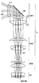
図20に示すように、撮影レンズ系(TL)内の光路の途中には平面状の反射面(RL)が配置されており、反射面(RL)の前側と後側には各々少なくとも1枚のレンズが配置されている。この反射面(RL)により、撮影レンズ系(TL)を屈曲光学系として使用するための光路の折り曲げが行われ、その際、光軸(AX)が略90度(つまり90度又は実質的に90度)折り曲げられるようにして光束が反射される。なお反射面(RL)は、プリズム類(直角プリズム等),ミラー類(平面ミラー等)等の反射部材により構成される。
【0017】
後述する各実施の形態では、複数の群から成るズームレンズ系が撮影レンズ系(TL)として用いられ、複数の群が光軸(AX)に沿って移動し、各群の間隔を変化させることにより変倍(すなわちズーミング)が行われる。撮像素子(SR)としては、例えば複数の画素から成るCCD(Charge Coupled Device)やCMOS(Complementary Metal Oxide Semiconductor)センサー等の固体撮像素子が用いられ、ズームレンズ系により形成された光学像が撮像素子(SR)により電気的な信号に変換される。
【0018】
またズームレンズ系で形成されるべき光学像は、撮像素子(SR)の画素ピッチにより決定される所定の遮断周波数特性を有する光学的ローパスフィルター{平行平面板(OF)から成る。}を通過することにより、電気的な信号に変換される際に発生するいわゆる折り返しノイズが最小化されるように、空間周波数特性が調整される。光学的ローパスフィルターとしては、例えば所定の結晶軸方向が調整された水晶等を材料とする複屈折型ローパスフィルターや、必要とされる光学的な遮断周波数特性を回折効果により達成する位相型ローパスフィルター等が適用可能である。撮像素子(SR)で生成した信号は、必要に応じて所定のデジタル画像処理や画像圧縮処理等が施されてデジタル映像信号としてメモリー(半導体メモリー,光ディスク等)に記録されたり、場合によってはケーブルを介したり赤外線信号に変換されたりして他の機器に伝送される。
【0019】
なお、図20に示す撮像レンズ装置(10)では、撮影レンズ系(TL)によって拡大側(共役長の長い側)の被写体から縮小側(共役長の短い側)の撮像素子(SR)への縮小投影が行われるが、撮像素子(SR)の代わりに2次元画像を表示する表示素子(例えば液晶表示素子)を用い、撮影レンズ系(TL)を投影レンズ系として使用すれば、縮小側の画像表示面から拡大側のスクリーン面への拡大投影を行う画像投影装置を構成することができる。つまり、以下に説明する各実施の形態のズームレンズ系は、撮影レンズ系(TL)としての使用に限らず、投影レンズ系としても好適に使用することが可能である。
【0020】
図1〜図5は、第1〜第5の実施の形態を構成するズームレンズ系にそれぞれ対応する光学構成図であり、広角端(W)でのレンズ配置,光路等を光路展開状態における光学断面で示している。また、図6〜図10は、第1〜第5の実施の形態を構成するズームレンズ系にそれぞれ対応する光学構成図であり、広角端(W)でのレンズ配置,光路等を光路折り曲げ状態における光学断面で示している。図1〜図5中、矢印m2,m3は広角端(W)から望遠端(T)へのズーミングにおける第2群(GR2),第3群(GR3)の移動をそれぞれ模式的に示しており、図5中の矢印mSは絞り(ST)がズーミングにおいて位置固定であることを示している。また図1〜図5中、ri(i=1,2,3,...)が付された面は物体側から数えてi番目の面(riに*印が付された面は非球面)であり、di(i=1,2,3,...)が付された軸上面間隔は、物体側から数えてi番目の軸上面間隔のうち、ズーミングにおいて変化する可変間隔である。
【0021】
各実施の形態のズームレンズ系はいずれも、物体側から順に、負のパワーを有する第1群(GR1)と、正のパワーを有する第2群(GR2)と、正のパワーを有する第3群(GR3)と、から成り(パワー:焦点距離の逆数で定義される量)、第2群(GR2)と第3群(GR3)を可動群として各群間隔を変化させることによりズーミングを行う3群ズームレンズである。第1〜第5の実施の形態(図1〜図5)では、広角端(W)から望遠端(T)までのズーミングに際し、第2群(GR2)が物体側に移動する。つまり、広角端(W)から望遠端(T)までのズーミングに際し、第2群(GR2)は像側から物体側へ単調に移動することにより、像面(IM)に対する相対位置を変化させる。
【0022】
第3群(GR3)のズーム移動は、第1〜第4の実施の形態(図1〜図4)と第5の実施の形態(図5)とで異なっている。第1〜第4の実施の形態では、広角端(W)から望遠端(T)までのズーミングに際し、第3群(GR3)が像側に凸のUターン形状の軌跡を描くように移動する。つまり、広角端(W)から望遠端(T)までのズーミングに際し、第3群(GR3)が最初に物体側から像側へ移動し、その後、望遠端(T)付近で像側から物体側へ移動することにより、像面(IM)に対する相対位置を変化させる。第3群(GR3)のズーム移動方向の変化点は、後でデータを挙げて具体的に示すように、中間焦点距離状態(M)と望遠端(T)との間に存在する。第5の実施の形態では、広角端(W)から望遠端(T)までのズーミングに際し、第3群(GR3)が像側に移動する。つまり、広角端(W)から望遠端(T)までのズーミングに際し、第3群(GR3)が物体側から像側へ単調に移動することにより、像面(IM)に対する相対位置を変化させる。
【0023】
いずれの実施の形態においても、第1群(GR1)は固定群であり、平行平面板(OF)及び撮像素子(SR)と共にズーミング中位置固定、つまり広角端(W)から望遠端(T)までのズーミングに際し像面(IM)に対して位置固定になっている。また、第1〜第4の実施の形態では第1群(GR1)と第2群(GR2)との間に絞り(ST)が配置されており、第5の実施の形態では第2群(GR2)と第3群(GR3)との間に絞り(ST)が配置されている。第1〜第4の実施の形態における絞り(ST)は第2群(GR2)と共にズーム移動し、第5の実施の形態における絞り(ST)は、第1群(GR1)と同様、ズーミング中位置固定になっている。またいずれの実施の形態においても、撮像素子(SR)を備えたカメラ(20,図20)に用いられる撮像レンズ装置(10)として、光学的ローパスフィルター,赤外カットフィルター等の光学フィルターに相当する2枚のガラス製平行平面板(OF)が、ズームレンズ系の像面(IM)側に配置されている。各実施の形態のレンズ構成を以下に詳しく説明する。
【0024】
第1の実施の形態(図1,図6)では、負・正・正の3群ズーム構成において各群が以下のように構成されている。第1群(GR1)は、物体側から順に、第1,第2,第3レンズ(L1,L2,L3)と、第1,第2レンズ(L1,L2)間に挿入されたプリズム(PR)と、で構成されている。第1レンズ(L1)は両面が非球面から成る像側に凹の負メニスカスレンズから成っており、プリズム(PR)は光軸(AX)を90度曲げるための反射面(RL,図20)を有する直角プリズムから成っている。第2レンズ(L2)は両凹の負レンズから成っており、第3レンズ(L3)は両凸の正レンズから成っており、第2レンズ(L2)と第3レンズ(L3)とで接合レンズを構成している。第2群(GR2)は、物体側から順に、両面が非球面から成る物体側に凸の正メニスカスレンズと、像側に凹の負メニスカスレンズ及び両凸の正レンズから成る接合レンズと、で構成されている。第3群(GR3)は、物体側から順に、物体側に凹の負メニスカスレンズと、両面が非球面から成る両凸の正レンズと、で構成されている。
【0025】
第2の実施の形態(図2,図7)では、負・正・正の3群ズーム構成において各群が以下のように構成されている。第1群(GR1)は、物体側から順に、第1,第2,第3レンズ(L1,L2,L3)と、第1,第2レンズ(L1,L2)間に挿入されたプリズム(PR)と、で構成されている。第1レンズ(L1)は両面が非球面から成る像側に凹の負メニスカスレンズから成っており、プリズム(PR)は光軸(AX)を90度曲げるための反射面(RL,図20)を有する直角プリズムから成っている。第2レンズ(L2)は両凹の負レンズから成っており、第3レンズ(L3)は両凸の正レンズから成っており、第2レンズ(L2)と第3レンズ(L3)とで接合レンズを構成している。第2群(GR2)は、物体側から順に、物体側に凸の正メニスカスレンズと、両凹の負レンズと、両面が非球面から成る両凸の正レンズと、で構成されている。第3群(GR3)は、物体側から順に、物体側に凹の負メニスカスレンズと、両面が非球面から成る両凸の正レンズと、で構成されている。
【0026】
第3の実施の形態(図3,図8)では、負・正・正の3群ズーム構成において各群が以下のように構成されている。第1群(GR1)は、物体側から順に、第1,第2,第3レンズ(L1,L2,L3)と、第1,第2レンズ(L1,L2)間に挿入されたプリズム(PR)と、で構成されている。第1レンズ(L1)は両面が非球面から成る両凹の負レンズから成っており、プリズム(PR)は光軸(AX)を90度曲げるための反射面(RL,図20)を有する直角プリズムから成っている。第2レンズ(L2)は両凹の負レンズから成っており、第3レンズ(L3)は両凸の正レンズから成っている。第2群(GR2)は、物体側から順に、両凸の正レンズと、両面が非球面から成る両凹の負レンズと、で構成されている。第3群(GR3)は、物体側から順に、物体側に凹の負メニスカスレンズと、両面が非球面から成る両凸の正レンズと、で構成されている。
【0027】
第4の実施の形態(図4,図9)では、負・正・正の3群ズーム構成において各群が以下のように構成されている。第1群(GR1)は、物体側から順に、第1,第2,第3レンズ(L1,L2,L3)と、第1レンズ(L1)の像側面に密着した状態で第1,第2レンズ(L1,L2)間に挿入されたプリズム(PR)と、で構成されている。第1レンズ(L1)は物体側面が非球面から成る物体側に凹の負の平凹レンズから成っており、プリズム(PR)は光軸(AX)を90度曲げるための反射面(RL,図20)を有する直角プリズムから成っている。第2レンズ(L2)は両面が非球面から成る両凹の負レンズから成っており、第3レンズ(L3)は両凸の正レンズから成っている。第2群(GR2)は、物体側から順に、両凸の正レンズ及び両凹の負レンズから成る接合レンズと、像側に凹の負メニスカスレンズと、両面が非球面から成る物体側に凸の正メニスカスレンズと、で構成されている。第3群(GR3)は、物体側面が非球面から成る両凸の正レンズ1枚で構成されている。
【0028】
第5の実施の形態(図5,図10)では、負・正・正の3群ズーム構成において各群が以下のように構成されている。第1群(GR1)は、物体側から順に、第1,第2,第3レンズ(L1,L2,L3)と、第1,第2レンズ(L1,L2)間に挿入されたプリズム(PR)と、で構成されている。第1レンズ(L1)は両面が非球面から成る像側に凹の負メニスカスレンズから成っており、プリズム(PR)は光軸(AX)を90度曲げるための反射面(RL,図20)を有する直角プリズムから成っている。第2レンズ(L2)は両凹の負レンズから成っており、第3レンズ(L3)は両凸の正レンズから成っており、第2レンズ(L2)と第3レンズ(L3)とで接合レンズを構成している。第2群(GR2)は、物体側から順に、物体側面が非球面から成る物体側に凸の正メニスカスレンズと、像側に凹の負メニスカスレンズ及び両凸の正レンズから成る接合レンズと、で構成されている。第3群(GR3)は、物体側から順に、物体側に凹の負メニスカスレンズと、両面が非球面から成る両凸の正レンズと、で構成されている。
【0029】
上述したように各実施の形態のズームレンズ系は、物体側から順に負・正・正の3つのズーム群(GR1〜GR3)を有するとともに、その第1群(GR1)にプリズム(PR)を反射部材として有している。各実施の形態に用いられているプリズム(PR)は直角プリズムであり、そのプリズム(PR)により前述の反射面(RL,図20)が構成されている。つまり、図6〜図10に示されているように、プリズム(PR)はズームレンズ系の光軸(AX)を略90度折り曲げるように内部の反射面(RL)で光束を反射させる構成になっている。なお、プリズム(PR)は直角プリズムに限らず、例えば2以上の反射面(RL)でズームレンズ系の光軸(AX)を略90度折り曲げるように光束を反射させるものでもよい。
【0030】
通常の撮像素子の画面形状は長方形であり、各実施の形態に用いられている撮像素子(SR)の画面形状も長辺:短辺=4:3の比率の長方形になっている。このため、撮像レンズ装置(10)の薄型化を達成するには、撮像素子(SR)の短辺方向に光路を折り曲げることが好ましい。なお、図6〜図10に示されている光路の折り曲げ方向は撮像素子(SR)の短辺方向になっており、図1〜図5ではプリズム(PR)を平行平面板として表現することにより、その光路を直線的に展開した状態で示している。
【0031】
各実施の形態に用いられているプリズム(PR)は内部反射プリズムであるが、これに限るものではない。反射面(RL)を構成する反射部材としては、表面反射プリズム,内部反射平板ミラー,表面反射平板ミラー等、いずれの反射部材を採用してもよい。内部反射プリズムがプリズム内部で物体光を反射させるのに対し、表面反射プリズムは物体光をプリズム内部に入射させずに、プリズム表面を反射面(RL)として物体光を反射させるものである。また、表面反射平板ミラーがミラー表面を反射面(RL)として物体光を反射させるのに対し、内部反射平板ミラーはガラス板裏面を反射面(RL)として、ガラス板内に入射させた物体光を反射させるものである。
【0032】
上記反射部材のうち、カメラ(20)の薄型化の達成には内部反射プリズムが最適である。内部反射プリズムを採用した場合、物体光はプリズム媒質中を通過することになるため、物体光がプリズムを透過する際の面間隔は物理的に短くなる。このため、反射面(RL)の構成に内部反射プリズムを採用した場合、光学的に等価な構成をよりコンパクトなスペースで達成することができるので好ましい。また、反射面(RL)は完全な全反射面でなくてもよい。つまり、反射面(RL)のうち一部分の反射率を適宜調整して一部の物体光を分岐するようにし、測光用センサーや測距用センサーに入射させてもよい。さらに、反射面(RL)全体の反射率を適宜調整してファインダー光を分岐させてもよい。
【0033】
従来の撮像レンズ装置のように、光軸の方向を変更することなくズームレンズ系に含まれるレンズや絞り等の光学要素を直線的に配列した場合、撮像レンズ装置の厚み方向の大きさは、ズームレンズ系の最も物体側の光学要素から撮像素子までの大きさで事実上決定される。ところが、半導体素子等の画像処理能力の向上により、パーソナルコンピュータ,モバイルコンピュータ,携帯電話,携帯情報端末等に搭載される撮像レンズ装置にも、従来のように簡易なものではなく、より高画素,高倍率,高画質を有する撮像レンズ装置が求められるようになってきている。このため、撮像レンズ装置に含まれるズームレンズ系のレンズ素子の枚数も増大する一方であり、非使用時(いわゆる沈胴状態)でもレンズ素子の厚みのため薄型化を達成することが困難になっている。
【0034】
これに対し、各実施の形態のズームレンズ系のように、反射面(RL)により物体光を反射させて光軸(AX)を略90度折り曲げる構成を採用すれば、撮像レンズ装置(10)の厚さ方向の大きさを、最も物体側に位置する第1レンズ(L1)から反射面(RL)までの大きさにまで小さくすることが可能になる。したがって、撮像レンズ装置(10)の見かけ上の薄型化・小型化を達成することが可能になる。また、反射面(RL)で光軸(AX)を略90度折り曲げる構成を採用すると、反射面(RL)近傍で物体光の光路を重ね合わせることができるため、空間を有効に利用することが可能となり、撮像レンズ装置(10)の更なる小型化を達成することができる。
【0035】
各実施の形態のように、反射面(RL)の位置は第1群(GR1)の内部であることが好ましい。最も物体側に配置された第1群(GR1)の内部に反射面(RL)を配置することにより、撮像レンズ装置(10)の厚さ方向の大きさを最小にすることが可能になる。なお必要に応じて、光軸(AX)の折り曲げ角度を90度以外の角度に設定してもよいが、光軸(AX)の折り曲げ角度が90度に近いほど撮像レンズ装置(10)をよりコンパクトにすることが可能になる。また必要に応じて、反射部材の反射面(RL)にパワーを持たせてもよく、反射面(RL)の代わりに屈折面や回折面を用いて光軸(AX)を折り曲げるようにしてもよい。
【0036】
各実施の形態のようにプリズム(PR)等の反射部材で屈曲光学系を構成する場合、以下の条件式(1)を満足することが望ましい。
2.5<Dref/Ymax<4 …(1)
ただし、
Dref:反射部材直前の物体側光学部品から反射部材直後の像側光学部品までの軸上面間隔の和、
Ymax:最大像高、
である。
【0037】
条件式(1)は、デジタルカメラ等のカメラの薄型化に最適な反射部材付近の構成を規定している。条件式(1)の上限を越えると、光路折り曲げ部分の大きさが大きくなり、ズームレンズ系の見かけの厚みを小さくすることができなくなり、薄型デジタルカメラを実現することが困難になる。逆に条件式(1)の下限を越えると、光路の折り曲げに必要なスペースを確保することが困難になり、結果として光路折り曲げ部で光線にケラレが発生してしまう。
【0038】
以下の条件式(1a),(1b)のうちの少なくとも1つを満足することが更に望ましい。
2.5<Dref/Ymax<3.7 …(1a)
3.0<Dref/Ymax<4 …(1b)
【0039】
条件式(1a),(1b)は、上記条件式(1)が規定している条件範囲のなかでも、上記観点からより一層好ましい条件範囲を規定している。条件式(1a)を満足することによりカメラ(20)の薄型化を効果的に行うことが可能となり、条件式(1b)を満足することにより光路折り曲げ部での光線のケラレを効果的に回避することが可能となる。したがって、条件式(1a)及び条件式(1b)を満足することにより、薄型でケラレのない好ましい光学構成を実現することができる。
【0040】
一般に、負・正・正のズームレンズ系は、5倍〜10倍の高変倍には適していない。高変倍のズーミングを行おうとすると、望遠端(T)での第1群(GR1)及び第2群(GR2)のレンズ径が大きくなってしまうからである。しかし、各実施の形態のように3倍程度の変倍比を有するズームレンズ系の場合、第1群(GR1)が正パワーを有する(いわゆるプラスリード)のズームレンズ系に比べて、レンズ群の数が少なく、偏芯誤差感度も小さいことが知られている。したがって、各実施の形態で採用しているような負・正・正のズーム構成は、製造誤差が小さい、レンズ群の数が少ない、といったメリットがあるため好ましい。さらに、広角端(W)から望遠端(T)までのズーミングに際し像面(IM)に対して位置固定のレンズ群(例えば、コンデンサー機能を有するレンズ群)を、像面(IM)付近に配置してもよい。ズーミング中位置固定の正パワー又は負パワーのレンズ群を像面(IM)付近に追加すれば、若干の性能向上が見込まれる。その場合でも、各実施の形態で採用しているズームレンズ系と同等の効果を得ることは可能である。
【0041】
各実施の形態(図1〜図10)のように、第1群(GR1)がズーミング中位置固定であることが好ましい。つまり、物体側から順に、反射部材を有する負パワーの第1群(GR1)と、正パワーの第2群(GR2)と、正パワーの第3群(GR3)と、でズームレンズ系を構成するとともに、広角端(W)から望遠端(T)までのズーミングに際し、第1群(GR1)を像面(IM)に対して位置固定とすることが好ましい。第1群(GR1)をズーミング中位置固定とすることにより、ズームレンズ系の入射側での光軸(AX)方向の長さを短くすることができる。したがって、ズームレンズ系の小型化・高倍率化や撮像レンズ装置(10)及びカメラ(20)の薄型化を達成することが可能になる。
【0042】
第1群(GR1)には反射面(RL)が含まれているため、第1群(GR1)を移動させようとすると大きなスペースが必要になる。特に反射面(RL)をプリズム(PR)で構成している場合には、重量の大きなプリズム(PR)を移動させようとすると、駆動機構に大きな負担を強いることになってしまう。上記のように変倍時の第1群(GR1)のズーム位置を像面(IM)に対して固定とすれば、このような問題は発生せず、また全長が変化しない(つまりズーミングや沈胴による厚さの変化が生じない)ズームレンズ系を得ることができる。そして、ズームレンズ系の全長が変化しなければ、ズームレンズ系全体を箱型の構造で保持することができるので、ズームレンズ系を剛性の高い構造で保持することができる。
【0043】
負・正・正のズームレンズ系は、ズーミングにおける移動に関して2種類のタイプに大きく分けられる。第1のタイプでは、広角端(W)から望遠端(T)までのズーミングに際し、第2群(GR2)と第3群(GR3)とが互いに異なる速さで共に物体側に移動する。第2のタイプでは、広角端(W)から望遠端(T)までのズーミングに際し、第2群(GR2)が物体側に移動し、第3群(GR3)が像側に直線的に移動するか、又は像側に凸のUターン形状の軌跡を描いて移動する。2つのタイプでズーム移動が大きく異なっているのは、各群の変倍負担に大きな違いがあるからである。
【0044】
第1のタイプの場合、第2群(GR2)が増倍を行い、第3群(GR3)が減倍を行う。このような場合、第2群(GR2)の変倍負担が全系の変倍比よりも大きくなり、第2群(GR2)で発生する収差変動が大きくなってしまい好ましくない。第2のタイプの場合、第2群(GR2)と第3群(GR3)とで変倍を分担するので、ズーミングにおける収差変動は小さい。このため、少ないレンズ枚数でもズーム全域で良好な収差性能を得ることができる。したがって各実施の形態のように、広角端(W)から望遠端(T)までのズーミングに際し、第2群(GR2)が物体側に移動し、第3群(GR3)が像側に移動するか、あるいは像側に凸のUターン形状の軌跡を描くように移動することが好ましい。ただし、像側に凸のUターン形状の軌跡を描く第3群(GR3)の移動に対して、第2群(GR2)の物体側への移動と第3群(GR3)の像側への移動は、直線的(つまり単調)である。
【0045】
上記第2のタイプのズーミングを行うには、第2群(GR2)の変倍負担が全系の変倍負担よりも小さいことが必要である。具体的には以下の条件式(2)を満足することが望ましい。
1.0<(ft・m2w)/(fw・m2t) …(2)
ただし、
fw:広角端(W)でのズームレンズ系全体の焦点距離、
ft:望遠端(T)でのズームレンズ系全体の焦点距離、
m2w:広角端(W)での第2群(GR2)の結像倍率、
m2t:望遠端(T)での第2群(GR2)の結像倍率、
である。
【0046】
条件式(2)の下限を越えると、第2群(GR2)の変倍負担が大きくなりすぎるので、良好な性能を得ることが困難になる。この観点から以下の条件式(2a)を満足することが更に望ましい。条件式(2a)を満たすことにより、更に良好な性能を得ることができる。
1.2<(ft・m2w)/(fw・m2t) …(2a)
【0047】
前述したように第1群(GR1)にはズームレンズ系の光軸(AX)を略90度折り曲げるように光束を反射させるプリズム(PR)が反射部材として含まれているが、各実施の形態のズームレンズ系のように、反射部材の物体側に非球面を有する負パワーの第1レンズ(L1)を配置することが好ましい。プリズム(PR)等の反射部材の物体側に配置されるレンズが単レンズであること、つまり、パワーを有する光学素子として第1レンズ(L1)のみを反射部材の物体側に配置することにより、光軸(AX)が折り曲げられたズームレンズ系の幅{つまりズームレンズ系の入射側での光軸(AX)方向の長さ}を小さくすることができ、撮像レンズ装置(10)の薄型化を達成することが可能となる。
【0048】
また、各実施の形態ではプリズム(PR)の光入射側面と光出射側面がいずれも平面から成っており、第4の実施の形態では第1レンズ(L1)の光出射側面も平面から成っている。しかも第4の実施の形態では、第1レンズ(L1)の光出射側面とプリズム(PR)の光入射側面とが接合されており(すなわち面間隔ゼロ)、後でデータを挙げて具体的に示すように、第1レンズ(L1)とプリズム(PR)とが同じガラス材料から成っている。このことから、第4の実施の形態では第1レンズ(L1)と内部反射プリズム(PR)とを一体部品とみなしてもよいことになる。つまり第1レンズ(L1)及びプリズム(PR)は、物体側に凹面を有するプリズム、又は光入射側面が凹面から成るプリズムと等価である、ということができる。
【0049】
各実施の形態のように第1群(GR1)が負パワーを有するズームレンズ系において、広角端(W)で発生する歪曲収差と像面湾曲を補正することは、一般に極めて難しい。レンズ枚数を多くすることによってこの問題を解決することは通常可能であるが、レンズ枚数を増やせば収差性能の低下を招くおそれがある。例えば第1の実施の形態のように、第1レンズ(L1)と接合レンズ(L2,L3)との間にプリズム(PR)を挿入した場合、プリズム(PR)が無い場合と比べて、第1群(GR1)の像側主点位置が物体側に大きく移動し、パワーも弱くなってしまう。同じパワーを得るためには各レンズのパワーを強くする必要があるが、パワーを強くすると像面湾曲が更に大きく発生してしまう。各実施の形態では第1レンズ(L1)に非球面を導入することにより、構成上発生する歪曲収差,非点収差等の補正を行っている。また、第1レンズ(L1)に非球面を導入することにより、第1レンズ(L1)のパワーを強くすることができるため、結果として反射部材での光路幅を小さくすることができる。
【0050】
上記効果を得るためには、光軸(AX)から離れるほど第1レンズ(L1)の負パワーが弱くなる非球面を、第1レンズ(L1)に導入することが望ましい。具体的には以下の条件式(3)を満足することが望ましい。
0<Xa−Xb …(3)
ただし、
Xa:第1レンズ(L1)の物体側面における最大有効範囲での近軸曲率からの光軸(AX)方向の変位量(像側への変位を正とする。)、
Xb:第1レンズ(L1)の像側面における最大有効範囲での近軸曲率からの光軸(AX)方向の変位量(像側への変位を正とする。)、
である。
【0051】
条件式(3)は、第1レンズ(L1)の物体側面と像側面との非球面効果の和を規定している。変位量Xaが大きくなると第1レンズ(L1)の正パワーが大きくなり、変位量Xbが大きくなると第1レンズ(L1)の負パワーが大きくなる。条件式(3)を満たすと、変位量Xaが変位量Xbよりも大きくなるので、最大有効範囲での光線に対して正パワーが大きくなる。したがって、光軸(AX)から離れるほど第1レンズ(L1)の負パワーが弱くなり、負パワーにより発生する歪曲収差,非点収差の補正を良好に行うことができる。条件式(3)を満足しない場合、第1レンズ(L1)の非球面が歪曲収差や非点収差を増幅する役割を持つことになるため、良好な性能を得ることが困難になる。
【0052】
第1群(GR1)を第1レンズ(L1)と反射部材のみで構成すると、コンパクトにはなるが、色収差やその他の収差を補正することができなくなる。したがって、諸収差を良好に補正するためには、プリズム(PR)等の反射部材の像側に少なくとも1枚の負レンズと少なくとも1枚の正レンズとから成るレンズ群を配置することが好ましい。したがって、第1群(GR1)が、物体側から順に、非球面を有する負パワーの第1レンズ(L1)と、ズームレンズ系の光軸を略90度折り曲げるように光束を反射させる反射部材と、少なくとも1枚の負レンズと少なくとも1枚の正レンズとから成るレンズ群と、で構成されることが好ましい。そして、反射部材の像側に配置されるレンズ群は、正パワーを有することが更に好ましい。
【0053】
また、第1群(GR1)中のプリズム(PR)等の反射部材の像側には、負レンズから成る第2レンズ(L2)と正レンズから成る第3レンズ(L3)とで構成された接合レンズを、上記レンズ群として配置することが好ましく、第1,第2,第5の実施の形態のように、両凹の負レンズから成る第2レンズ(L2)と両凸の正レンズから成る第3レンズ(L3)とで構成された接合レンズを、上記レンズ群として配置することが更に好ましい。接合レンズはズームレンズ系に対する組み込みが容易であるため、反射部材の像側に負・正のレンズ2枚から成る接合レンズを配置すれば、簡単な構成で収差補正を良好に行うことが可能になる。
【0054】
先に述べたように各実施の形態のズームレンズ系では、ズーミングにおいて第1群(GR1)が固定であり、第2群(GR2)と第3群(GR3)がズーム移動することにより変倍を行っている。従来の負・正・正のズームレンズ系では、第1群のズーム移動により収差変動を補正して、第3群をレンズ1枚構成とするのが一般的である。しかし、第1群がズーム位置固定の場合には、第3群に対する収差変動がかなり大きくなり、レンズ1枚構成ではズーミングでの収差変動を補正することが困難になる。そこで、第1〜第3,第5の実施の形態のように、少なくとも1枚の負レンズと、少なくとも1枚の正レンズと、で第3群(GR3)を構成することが好ましい。このように負レンズと正レンズをそれぞれ少なくとも1枚用いれば、色収差等を補正することができるので、良好な性能を確保することができる。諸収差をより一層良好に補正するには、第1〜第3,第5の実施の形態のように、物体側から順に像側に凸のメニスカス形状を有する負レンズと正レンズとで、第3群(GR3)を構成することが更に好ましい。
【0055】
デジタルカメラの薄型化には、レンズやプリズムといった光学部品が薄い領域内に配置できることが必要であるが、それに加えて鏡胴や駆動部品を含んだ構成がコンパクトであることも必要である。第1〜第4の実施の形態では、開口絞り(ST)が第2群(GR2)の物体側に配置されており、ズーミングに際して第2群(GR2)と共に移動する構成になっている。通常のデジタルカメラでは開口絞り(ST)の位置にメカシャッターを配置するが、メカシャッターを用いる場合、その遮光部が退避する場所を確保する必要がある上に、駆動モーター等の駆動素子も必要になる。したがって、かなり大きなスペースが必要となる。
【0056】
第1〜第4の実施の形態のように絞り(ST)が移動群と共にズーム移動する場合、大きなスペースを必要とするメカシャッターが移動群に搭載されることになるため、移動群自体が大きくなってしまう。その上、駆動ユニットに過大な負担がかかるため、全体として非常に大きな構成になってしまう可能性がある。つまり、光学部品だけがコンパクトであっても、構成によっては小型化が困難になる場合がある。そこで、第1〜第4の実施の形態では、移動群にシャッター機構を搭載しないことが、メカ構成を含めた小型化に際しては好ましい。その場合、撮像素子(SR)に電子シャッター機能を有することで、メカシャッターの代用とすることができる。
【0057】
上記理由により、撮像素子(SR)は電子シャッター機能を有する固体撮像素子であることが望ましく、プログレッシブ方式のCCDであることが更に望ましい。しかしながら、現在市販されている電子シャッター機能を有する固体撮像素子のシャッター機能は、メカシャッターほど十分ではなく、電荷転送時に素子の配線部に光が照射されるとノイズが発生することが多い。そこで、第2群(GR2)と第3群(GR3)の固定スペースに遮光機能を有する部材(メカシャッター,液晶シャッター等)を配置し、撮影時には以下の第1〜第3の工程を順に行うことが望ましい。
第1の工程:ユーザーの撮影要求に応じて電子シャッターを駆動する工程。
第2の工程:遮光機能を有する部材を駆動させて固体撮像素子に光が照射されないようにする工程。
第3の工程:固体撮像素子に溜まった電荷を画像処理装置に転送する工程。
【0058】
各実施の形態を構成しているズームレンズ系には、入射光線を屈折作用により偏向させる屈折型レンズ(つまり、異なる屈折率を有する媒質同士の界面で偏向が行われるタイプのレンズ)が用いられているが、使用可能なレンズはこれに限らない。例えば、回折作用により入射光線を偏向させる回折型レンズ,回折作用と屈折作用との組み合わせで入射光線を偏向させる屈折・回折ハイブリッド型レンズ,入射光線を媒質内の屈折率分布により偏向させる屈折率分布型レンズ等を用いてもよい。ただし、媒質内で屈折率が変化する屈折率分布型レンズは、その複雑な製法がコストアップを招くため、均質素材レンズを用いることが望ましい。また、開口絞り(ST)のほかに不要光をカットするための光束規制板等を必要に応じて配置してもよい。
【0059】
各実施の形態では、近接撮影を行う際のフォーカシングを、第3群(GR3)を物体側に繰り出すことにより行う構成になっている。従来より、ズーミングに対するレンズ駆動は、1つの駆動装置の動力をズームカムを通じて複数の移動レンズ群に伝達することで行われている。フォーカシングは、別の駆動装置を用いたフォーカスレンズ群の移動により行われている。しかし、各実施の形態のようにズーミングやフォーカシングで移動するレンズ群が2つであれば、カム等を使わずに2つのレンズ群にそれぞれ駆動装置を直接接続することができる。各レンズ群の移動量をコントロールすることによりズーミングやフォーカシングを行えば、カムが不要となるので構成を簡略化することができ、ひいては薄型化につながるので好ましい。また、前述したように負レンズと正レンズをそれぞれ少なくとも1枚用いて第3群(GR3)を構成し、第3群(GR3)を物体側に繰り出してフォーカシングを行う構成にすれば、フォーカシング時の収差変動を小さくすることができるので好ましい。
【0060】
【実施例】
以下、本発明を実施した撮像レンズ装置に用いられるズームレンズ系の構成等を、コンストラクションデータ等を挙げて更に具体的に説明する。ここで挙げる実施例1〜5は、前述した第1〜第5の実施の形態にそれぞれ対応する数値実施例であり、第1〜第5の実施の形態を表す光学構成図(図1〜図10)は、対応する実施例1〜5のレンズ構成をそれぞれ示している。
【0061】
表1〜表4,表5〜表8,表9〜表12,表13〜表16,表17〜表20に、実施例1〜実施例5のコンストラクションデータを示し、表21に各条件式規定のパラメータに対応するデータ及び関連するデータを各実施例について示す。表1,表5,表9,表13,表17は、設計波長(λ0,単位:nm),最大像高(Ymax,単位:mm),並びに各焦点距離状態(W,M,T)に対応する全系の焦点距離(f,単位:mm)及びFナンバー(Fno)を示している。なお、Wは広角端(最短焦点距離状態)、Mはミドル(中間焦点距離状態)、Tは望遠端(最長焦点距離状態)である。
【0062】
表2,表6,表10,表14,表18は、物体面(OB)から像面(IM)までの基本的な光学構成(i:面番号)を各実施例について示しており、ri(i=0,1,2,3,...)は物体側から数えてi番目の面の曲率半径(mm)、di(i=0,1,2,3,...)は物体側から数えてi番目の面と(i+1)番目の面との間の軸上面間隔(mm)を示しており(d0:物体距離)、Ni(i=1,2,3,...),νi(i=1,2,3,...)は軸上面間隔diに位置する光学材料のd線に対する屈折率(Nd),アッベ数(νd)を示している。
【0063】
曲率半径riのデータに*印が付された面は、非球面(非球面形状の屈折光学面、非球面と等価な屈折作用を有する面等)であり、非球面の面形状を表わす以下の式(AS)で定義される。表3,表7,表11,表15,表19に、各実施例の非球面データを示す(ただしAi=0の場合は省略する。)。
x=(C0・y2)/[1+{1-(1+K)・C02・y2}1/2]+Σ(Ai・yi) …(AS)
ただし、式(AS)中、
x:高さyの位置での光軸(AX)方向の変位量(面頂点基準)、
y:光軸(AX)に対して垂直な方向の高さ、
C0:近軸曲率(=1/ri)、
K:円錐係数、
Ai:i次の非球面係数、
である。
【0064】
軸上面間隔diのデータに#印が付された空気間隔は、ズーミングやフォーカシングにより変化する可変間隔である。表4,表8,表12,表16,表20に、各実施例の可変間隔データを示す。POS1,POS2,POS3は無限遠合焦状態、POS4,POS5,POS6は近接距離合焦状態、POS1,POS4は広角端(W)、POS2,POS5はミドル(M)、POS3,POS6は望遠端(T)での可変間隔データをそれぞれ示している。
【0065】
図11〜図19は実施例1〜実施例5の収差図であり、図11,図13,図15,図17,図18のPOS1,POS2,POS3は実施例1〜5の無限遠合焦状態での諸収差を示しており、図12,図14,図16,図19のPOS4,POS5,POS6は実施例1〜3,5の近接距離合焦状態での諸収差をそれぞれ示している。また、(A)〜(C)は広角端(W)、(D)〜(F)はミドル(M)、(G)〜(I)は望遠端(T)での諸収差をそれぞれ示している。
【0066】
図11〜図19中、(A),(D),(G)は球面収差図、(B),(E),(H)は非点収差図、(C),(F),(I)は歪曲収差図である。球面収差図は、設計波長λ0,g線,C線に対する各球面収差量を、近軸像面からの光軸(AX)方向のズレ量(横軸,単位:mm)で表しており、縦軸は瞳への入射高さをその最大高さで規格化した値(すなわち相対瞳高さ)を表している。非点収差図において、破線(DT)はタンジェンシャル像面、実線(DS)はサジタル像面を、近軸像面からの光軸(AX)方向のズレ量(横軸,単位:mm)で表しており、縦軸は像高(IMG HT,単位:mm)を表している。歪曲収差図において、横軸は設計波長λ0に対する歪曲(%)を表しており、縦軸は像高(IMG HT,単位:mm)を表している。
【0067】
【表1】

【表2】
【表3】
【表4】
【表5】
【表6】
【表7】
【表8】
【表9】
【表10】
【表11】
【表12】
【表13】
【表14】
【表15】
【表16】
【表17】
【表18】
【表19】
【表20】
【表21】
なお、前述した各実施の形態や各実施例には、以下の構成を有する発明が含まれている。そしてこれらの構成によると、薄型でコンパクトなズームレンズを実現することができる。そして、それを撮像レンズ装置やカメラに適用することにより、当該装置の薄型・コンパクト化,低コスト化,高性能化等に寄与することができる。
【0089】
(A1) 物体側から順に、反射部材を有する負パワーの第1群と、正パワーの第2群と、正パワーの第3群とを有し、広角端から望遠端までのズーミングに際し、前記第1群が像面に対して位置固定であり、前記第2群が物体側に移動し、前記第3群が像側に移動するか、あるいは像側に凸のUターン形状の軌跡を描くように移動することを特徴とするズームレンズ。
(A2) 前記反射部材がズームレンズ系の光軸を略90度折り曲げるように光束を反射させることを特徴とする上記(A1)記載のズームレンズ。
(A3) 前記第1群が、物体側から順に、非球面を有する負パワーの第1レンズと、前記反射部材と、少なくとも1枚の負レンズと少なくとも1枚の正レンズとから成るレンズ群と、で構成され、前記反射部材がズームレンズ系の光軸を略90度折り曲げるように光束を反射させることを特徴とする上記(A1)又は(A2)記載のズームレンズ。
(A4) 前記第3群が、少なくとも1枚の負レンズと、少なくとも1枚の正レンズと、から成ることを特徴とする上記(A1)〜(A3)のいずれか1項に記載のズームレンズ。
(A5) 前記条件式(1),(1a),(1b),(2),(2a),(3)のうちの少なくとも1つを満たすことを特徴とする上記(A1)〜(A4)のいずれか1項に記載のズームレンズ。
【0090】
(A6) 前記反射部材の物体側に、パワーを有する光学素子として、非球面を有する負レンズが1枚のみ配置されていること特徴とする上記(A1)〜(A5)のいずれか1項に記載のズームレンズ。
(A7) 前記反射部材がプリズムから成り、前記負レンズと接合されていることを特徴とする上記(A6)記載のズームレンズ。
(A8) 前記反射部材が、物体側に凹面を有するプリズムから成ること特徴とする上記(A1)〜(A5)のいずれか1項に記載のズームレンズ。
(A9) 前記反射部材の像側に、少なくとも1枚の負レンズと少なくとも1枚の正レンズとから成る正レンズ群が配置されていること特徴とする上記(A1)〜(A5)のいずれか1項に記載のズームレンズ。
(A10) 前記正レンズ群が、負レンズと正レンズとの接合レンズから成ることを特徴とする上記(A9)記載のズームレンズ。
(A11) 前記第3群が、物体側から順に、像側に凸の負メニスカスレンズと、正レンズと、から成ることを特徴とする上記(A1)〜(A10)のいずれか1項に記載のズームレンズ。
【0091】
(A12) さらに、前記第1群と前記第2群との間に絞りを有することを特徴とする上記(A1)〜(A11)のいずれか1項に記載のズームレンズ。
(A13) さらに、前記第2群と前記第3群との間に絞りを有することを特徴とする上記(A1)〜(A11)のいずれか1項に記載のズームレンズ。
(A14) 広角端から望遠端までのズーミングに際し、前記絞りが像面に対して位置固定であることを特徴とする上記(A12)又は(A13)記載のズームレンズ。
(A15) 広角端から望遠端までのズーミングに際し、前記絞りが前記第2群と共に移動することを特徴とする上記(A12)又は(A13)記載のズームレンズ。
【0092】
(B1) 上記(A1)〜(A15)のいずれか1項に記載のズームレンズと、そのズームレンズにより形成された光学像を電気的な信号に変換する撮像素子と、を備えたことを特徴とする撮像レンズ装置。
(B2) 前記撮像素子が、電子シャッター機能を有する固体撮像素子であることを特徴とする上記(B1)記載の撮像レンズ装置。
(B3) 上記(B1)又は(B2)記載の撮像レンズ装置を備え、被写体の静止画撮影,動画撮影のうちの少なくとも一方に用いられることを特徴とするカメラ。
(B4) デジタルカメラ;ビデオカメラ;又はデジタルビデオユニット,パーソナルコンピュータ,モバイルコンピュータ,携帯電話,携帯情報端末,若しくはこれらの周辺機器に内蔵又は外付けされるカメラであることを特徴とする上記(B3)記載のカメラ。
【0093】
【発明の効果】
以上説明したように本発明によれば、物体側から順に負・正・正のズーム群を有するズームレンズ系において、第1群が像面に対してズーミング中位置固定であり、第2群が物体側にズーム移動し、第3群が像側にズーム移動するか、あるいは像側に凸のUターン形状の軌跡を描くようにズーム移動する構成になっているため、高画質を満足する高性能で小型のズームレンズ系を備えた薄型の撮像レンズ装置を実現することができる。そして本発明に係る撮像レンズ装置を、デジタルカメラ;ビデオカメラ;デジタルビデオユニット,パーソナルコンピュータ,モバイルコンピュータ,携帯電話,携帯情報端末,これらの周辺機器(マウス,スキャナー,プリンター,その他のデジタル入出力装置)等に内蔵又は外付けされるカメラ等に用いれば、これらの機器の薄型・コンパクト化,低コスト化,高性能化等に寄与することができる。
【0094】
第1群を、物体側から順に、非球面を有する負パワーの第1レンズと、ズームレンズ系の光軸を略90度折り曲げるように光束を反射させる反射部材と、少なくとも1枚の負レンズと少なくとも1枚の正レンズとから成るレンズ群と、で構成することにより、コンパクトな構成で歪曲収差や非点収差等の補正が可能となる。第3群を、少なくとも1枚の負レンズと、少なくとも1枚の正レンズと、で構成することにより、色収差等の補正が可能となる。また、撮像素子として電子シャッター機能を有する固体撮像素子を用いることにより、撮像レンズ装置をより一層小型化することができる。
【図面の簡単な説明】
【図1】第1の実施の形態(実施例1)の光路及びレンズ構成を光路展開状態で示す光学構成図。
【図2】第2の実施の形態(実施例2)の光路及びレンズ構成を光路展開状態で示す光学構成図。
【図3】第3の実施の形態(実施例3)の光路及びレンズ構成を光路展開状態で示す光学構成図。
【図4】第4の実施の形態(実施例4)の光路及びレンズ構成を光路展開状態で示す光学構成図。
【図5】第5の実施の形態(実施例5)の光路及びレンズ構成を光路展開状態で示す光学構成図。
【図6】第1の実施の形態(実施例1)の光路及びレンズ構成を光路折り曲げ状態で示す光学構成図。
【図7】第2の実施の形態(実施例2)の光路及びレンズ構成を光路折り曲げ状態で示す光学構成図。
【図8】第3の実施の形態(実施例3)の光路及びレンズ構成を光路折り曲げ状態で示す光学構成図。
【図9】第4の実施の形態(実施例4)の光路及びレンズ構成を光路折り曲げ状態で示す光学構成図。
【図10】第5の実施の形態(実施例5)の光路及びレンズ構成を光路折り曲げ状態で示す光学構成図。
【図11】実施例1の無限遠合焦状態での収差図。
【図12】実施例1の近接距離合焦状態での収差図。
【図13】実施例2の無限遠合焦状態での収差図。
【図14】実施例2の近接距離合焦状態での収差図。
【図15】実施例3の無限遠合焦状態での収差図。
【図16】実施例3の近接距離合焦状態での収差図。
【図17】実施例4の無限遠合焦状態での収差図。
【図18】実施例5の無限遠合焦状態での収差図。
【図19】実施例5の近接距離合焦状態での収差図。
【図20】本発明に係る撮像レンズ装置の概略光学構成を示す模式図。
【符号の説明】
TL …撮影レンズ系(ズームレンズ系)
PR …プリズム(反射部材)
RL …反射面
GR1 …第1群
GR2 …第2群
GR3 …第3群
ST …絞り
OF …平行平面板
SR …撮像素子
AX …光軸[0001]
BACKGROUND OF THE INVENTION
The present invention relates to an imaging lens device, and in particular, an imaging lens device that optically captures an image of a subject by an optical system and outputs it as an electrical signal by an imaging device {for example, a digital still camera; a digital video camera; a personal computer , Main components of a camera built in or externally attached to a mobile computer, a mobile phone, a personal digital assistant (PDA), etc.}, in particular, an imaging lens device having a small zoom lens system, and the imaging lens device It is related with the thin camera provided with.
[0002]
[Prior art]
In recent years, with the spread of personal computers and the like, digital still cameras and digital video cameras (hereinafter simply referred to as “digital cameras”) that can easily capture image information into digital devices are becoming popular at the individual user level. . Digital cameras are expected to become increasingly popular as image information input devices. The image quality of such a digital camera is generally determined by the number of pixels of a solid-state imaging device such as a CCD (Charge Coupled Device). At present, digital cameras for general use have a high pixel count exceeding 1 million pixels, and the image quality is approaching that of a silver salt film camera. For this reason, the photographing lens system is required to have high optical performance corresponding to the increase in the number of pixels of the image sensor.
[0003]
In general digital cameras, image scaling, particularly optical scaling with little image degradation, is desired. On the other hand, it is desired to reduce the thickness to improve portability. Various types of zoom lens systems have been proposed in the past to meet the demand for higher image quality and thinner digital cameras (see, for example,
[0004]
[Patent Document 1]
JP 2001-296476 A
[Patent Document 2]
JP 2000-137164 A
[Patent Document 3]
JP-A-8-248318
[Patent Document 4]
JP-A-9-133858
[Patent Document 5]
JP 2002-277736 A
[Patent Document 6]
JP 11-258678 A
[0005]
[Problems to be solved by the invention]
Most zoom lens systems for digital cameras that have been proposed conventionally employ a so-called collapsible lens barrel as a method for making the digital camera thinner. In the retractable lens barrel, the zoom lens system is retracted when the camera is not used and the distance between the lenses is kept to a minimum. When the camera is used, the zoom lens system is extended to the original lens arrangement state. Retained. In the zoom lens system described in
[0006]
The digital camera can also be made thinner by devising the arrangement of the zoom lens system in the camera. In a general digital camera, the zoom lens system is arranged so that the largest surface of the housing faces the subject. When the zoom lens system is arranged in such a manner, the length of the zoom lens system becomes the thickness of the digital camera. It will greatly affect. Therefore, if a zoom lens system as described in Patent Document 2 is arranged so that its optical axis is parallel to the largest surface of the housing, the thickness of the digital camera depends on the length of the zoom lens system. Since it will not be influenced, the digital camera can be made thinner. However, the camera becomes elongated and becomes very difficult for the user to use. Although it is possible to improve the usability by rotating the lens barrel at the time of use, since a rotating mechanism is required, the thickness of the digital camera increases as a result. In addition, since troublesome rotating operation must be performed at the start of shooting and at the end of shooting, this is also not preferable.
[0007]
As described above, enabling the photographing with the largest surface of the housing facing the subject is a requirement for realizing a thin digital camera with excellent operability. As an optical configuration satisfying this requirement, zoom lens systems proposed in Patent Documents 3 to 6 can be cited. The zoom lens systems described in Patent Documents 3 to 6 are configured such that the largest surface of the housing faces the subject by bending the optical path with a prism or mirror inserted between the lenses. However, none of them is configured to make the digital camera sufficiently thin.
[0008]
For example, in the zoom lens system described in Patent Document 3, the first lens group has a positive power (so-called plus lead) zoom configuration, and in the zoom lens system described in Patent Document 4, the first lens group consists of an afocal system. Zoom configuration. With these zoom configurations, it is difficult to scale with a small number of zoom components, resulting in a four component zoom. When there are many zoom components, the structure of the lens barrel becomes complicated, and the entire lens barrel including the driving parts becomes large, so that it is difficult to reduce the thickness of the camera. In the zoom lens system described in Patent Document 5, the mirror is deformed during zooming. The drive / control configuration for deforming the mirrors makes it difficult to reduce the thickness of the digital camera. In the zoom lens system described in
[0009]
The present invention has been made in view of such circumstances, and an object of the present invention is to provide a thin imaging lens device including a high-performance and compact zoom lens system that satisfies high image quality.
[0010]
[Means for Solving the Problems]
In order to achieve the above object, an imaging lens device according to a first aspect of the present invention includes a zoom lens system that is composed of a plurality of groups and performs zooming by changing the group interval, and an optical image formed by the zoom lens system. An image pickup lens device comprising: an image pickup device for converting into a general signal, wherein the zoom lens system includes, in order from the object side, a negative power first group having a reflecting member, and a positive power second group. And the third group of positive powerConsist ofIn zooming from the wide-angle end to the telephoto end, the first group is fixed with respect to the image plane, and the second group moves to the object side,The following conditional expression (2) Satisfied,The third group moves toward the image side, or moves so as to draw a U-turn locus that is convex toward the image side, and the first group is a negative power first having an aspheric surface in order from the object side. It is composed of a lens, the reflecting member, and a cemented lens made up of one negative lens and one positive lens, and reflects the light beam so that the reflecting member bends the optical axis of the zoom lens system by approximately 90 degrees. It is characterized by making it.
1.0 < (ft ・ m2w) / (fw ・ m2t) ... (2)
However,
fw : Focal length of the entire zoom lens system at the wide-angle end,
ft : Focal length of the entire zoom lens system at the telephoto end,
m2w : Image forming magnification of the second group at the wide-angle end,
m2t : Imaging magnification of the second group at the telephoto end,
It is.
[0012]
First2The imaging lens device of the invention is the above-mentioned first.1In the configuration of the invention, the third group includes at least one negative lens and at least one positive lens.
[0013]
First3The imaging lens device of the present invention is the above first.Or secondIn the configuration of the invention, the image sensor is a solid-state image sensor having an electronic shutter function.
[0014]
First4The camera of the present invention is the above first to first.3An imaging lens device according to any one of the inventions is provided.
[0015]
DETAILED DESCRIPTION OF THE INVENTION
Hereinafter, an imaging lens device embodying the present invention will be described with reference to the drawings. An imaging lens device that optically captures an image of a subject and outputs it as an electrical signal is a camera used for still image shooting or moving image shooting of a subject {eg, digital camera; video camera; digital video unit, personal computer, mobile It is a main component of a camera, built-in or externally attached to a computer, a mobile phone, a personal digital assistant (PDA), and peripheral devices (mouse, scanner, printer, other digital input / output devices) and the like. For example, as shown in FIG. 20, the imaging lens device (10) includes, in order from the object (subject) side, a photographing lens system (TL) that forms an optical image of the object, an optical filter (for example, an optical low-pass filter), and the like. And an image sensor (SR) that converts the optical image formed by the photographic lens system (TL) into an electrical signal, and is mounted on the camera (20). . If necessary, the unitized imaging lens device (10) may be configured to be detachable or rotatable with respect to the body of the camera (20).
[0016]
As shown in FIG. 20, a planar reflecting surface (RL) is disposed in the middle of the optical path in the photographic lens system (TL), and at least one sheet is provided on each of the front and rear sides of the reflecting surface (RL). Lens is arranged. By this reflecting surface (RL), the optical path for using the photographic lens system (TL) as a bending optical system is bent. At this time, the optical axis (AX) is approximately 90 degrees (that is, 90 degrees or substantially). (90 degrees) The light beam is reflected as if folded. The reflecting surface (RL) is configured by a reflecting member such as a prism (right angle prism or the like), a mirror (plane mirror or the like).
[0017]
In each embodiment described later, a zoom lens system composed of a plurality of groups is used as a photographic lens system (TL), and the plurality of groups move along the optical axis (AX) to change the interval between the groups. Thus, zooming is performed. As the imaging device (SR), for example, a solid-state imaging device such as a CCD (Charge Coupled Device) or a CMOS (Complementary Metal Oxide Semiconductor) sensor composed of a plurality of pixels is used, and an optical image formed by the zoom lens system is an imaging device. It is converted into an electrical signal by (SR).
[0018]
The optical image to be formed by the zoom lens system is composed of an optical low-pass filter {parallel plane plate (OF) having a predetermined cut-off frequency characteristic determined by the pixel pitch of the image sensor (SR). }, The spatial frequency characteristics are adjusted so that the so-called aliasing noise that occurs when converted into an electrical signal is minimized. As an optical low-pass filter, for example, a birefringent low-pass filter made of quartz or the like with a predetermined crystal axis direction adjusted, or a phase-type low-pass filter that achieves a required optical cutoff frequency characteristic by a diffraction effect Etc. are applicable. The signal generated by the image sensor (SR) is subjected to predetermined digital image processing, image compression processing, etc. as necessary, and recorded as a digital video signal in a memory (semiconductor memory, optical disk, etc.), or in some cases a cable Or is converted into an infrared signal and transmitted to another device.
[0019]
In the imaging lens device (10) shown in FIG. 20, a photographic lens system (TL) converts an object on the enlargement side (the longer conjugate length) to an image sensor (SR) on the reduction side (the shorter conjugate length). Although reduction projection is performed, if a display element (for example, a liquid crystal display element) that displays a two-dimensional image is used instead of the image pickup element (SR) and the photographing lens system (TL) is used as a projection lens system, the reduction side It is possible to configure an image projection apparatus that performs enlarged projection from the image display surface to the enlarged screen surface. That is, the zoom lens system according to each embodiment described below can be suitably used not only as a photographic lens system (TL) but also as a projection lens system.
[0020]
FIGS. 1 to 5 are optical configuration diagrams respectively corresponding to the zoom lens systems constituting the first to fifth embodiments. The lens arrangement at the wide angle end (W), the optical path, etc. are optical in the optical path expanded state. Shown in cross section. FIGS. 6 to 10 are optical configuration diagrams respectively corresponding to the zoom lens systems constituting the first to fifth embodiments, in which the lens arrangement at the wide-angle end (W), the optical path, etc. are bent in the optical path. The optical cross section is shown in FIG. 1 to 5, arrows m2 and m3 schematically show the movement of the second group (GR2) and the third group (GR3) during zooming from the wide-angle end (W) to the telephoto end (T), respectively. 5 indicates that the position of the aperture stop (ST) is fixed during zooming. 1 to 5, the surface with ri (i = 1, 2, 3,...) Is the i-th surface counted from the object side (the surface with ri marked with * is an aspherical surface). ), And the axis top surface interval with di (i = 1, 2, 3,...) Is a variable interval that changes during zooming among the i-th axis surface interval counted from the object side.
[0021]
In each of the zoom lens systems according to the embodiments, in order from the object side, the first group (GR1) having negative power, the second group (GR2) having positive power, and the third group having positive power. (Group: GR3) (Power: An amount defined by the reciprocal of the focal length), and the second group (GR2) and the third group (GR3) are movable groups, and zooming is performed by changing each group interval. This is a three-group zoom lens. In the first to fifth embodiments (FIGS. 1 to 5), the second lens group (GR2) moves to the object side during zooming from the wide-angle end (W) to the telephoto end (T). That is, during zooming from the wide-angle end (W) to the telephoto end (T), the second group (GR2) moves monotonically from the image side to the object side, thereby changing the relative position with respect to the image plane (IM).
[0022]
The zoom movement of the third group (GR3) differs between the first to fourth embodiments (FIGS. 1 to 4) and the fifth embodiment (FIG. 5). In the first to fourth embodiments, during zooming from the wide-angle end (W) to the telephoto end (T), the third group (GR3) moves so as to draw a U-turn-shaped locus convex toward the image side. . That is, during zooming from the wide-angle end (W) to the telephoto end (T), the third lens group (GR3) first moves from the object side to the image side, and then from the image side to the object side near the telephoto end (T). The relative position with respect to the image plane (IM) is changed. The change point of the zoom movement direction of the third group (GR3) exists between the intermediate focal length state (M) and the telephoto end (T), as will be specifically shown later with data. In the fifth embodiment, the third lens unit (GR3) moves to the image side during zooming from the wide-angle end (W) to the telephoto end (T). That is, during zooming from the wide-angle end (W) to the telephoto end (T), the third group (GR3) monotonously moves from the object side to the image side, thereby changing the relative position with respect to the image plane (IM).
[0023]
In any of the embodiments, the first group (GR1) is a fixed group and is fixed during zooming together with the plane parallel plate (OF) and the image sensor (SR), that is, from the wide angle end (W) to the telephoto end (T). The position is fixed with respect to the image plane (IM) during zooming up to. In the first to fourth embodiments, a diaphragm (ST) is disposed between the first group (GR1) and the second group (GR2). In the fifth embodiment, the second group ( A diaphragm (ST) is disposed between GR2) and the third group (GR3). The aperture stop (ST) in the first to fourth embodiments zooms together with the second group (GR2), and the aperture stop (ST) in the fifth embodiment is during zooming as in the first group (GR1). The position is fixed. In any of the embodiments, the imaging lens device (10) used in the camera (20, FIG. 20) including the imaging element (SR) corresponds to an optical filter such as an optical low-pass filter or an infrared cut filter. Two glass plane parallel plates (OF) are arranged on the image plane (IM) side of the zoom lens system. The lens configuration of each embodiment will be described in detail below.
[0024]
In the first embodiment (FIGS. 1 and 6), each group in the negative / positive / positive three-group zoom configuration is configured as follows. The first group (GR1) includes a prism (PR) inserted between the first, second and third lenses (L1, L2, L3) and the first and second lenses (L1, L2) in order from the object side. ) And. The first lens (L1) consists of a negative meniscus lens that is concave on the image side, both surfaces of which are aspheric, and the prism (PR) is a reflecting surface (RL, FIG. 20) for bending the optical axis (AX) by 90 degrees. It consists of a right angle prism with The second lens (L2) is composed of a biconcave negative lens, and the third lens (L3) is composed of a biconvex positive lens. The second lens (L2) and the third lens (L3) are cemented together. The lens is configured. The second group (GR2) includes, in order from the object side, a positive meniscus lens convex on the object side whose both surfaces are aspheric surfaces, and a cemented lens composed of a negative meniscus lens concave on the image side and a biconvex positive lens. It is configured. The third group (GR3) includes, in order from the object side, a negative meniscus lens that is concave on the object side, and a biconvex positive lens whose both surfaces are aspheric surfaces.
[0025]
In the second embodiment (FIGS. 2 and 7), each group in the negative / positive / positive three-group zoom configuration is configured as follows. The first group (GR1) includes a prism (PR) inserted between the first, second and third lenses (L1, L2, L3) and the first and second lenses (L1, L2) in order from the object side. ) And. The first lens (L1) consists of a negative meniscus lens that is concave on the image side, both surfaces of which are aspheric, and the prism (PR) is a reflecting surface (RL, FIG. 20) for bending the optical axis (AX) by 90 degrees. It consists of a right angle prism with The second lens (L2) is composed of a biconcave negative lens, and the third lens (L3) is composed of a biconvex positive lens. The second lens (L2) and the third lens (L3) are cemented together. The lens is configured. The second group (GR2) is composed of, in order from the object side, a positive meniscus lens convex toward the object side, a biconcave negative lens, and a biconvex positive lens whose both surfaces are aspheric surfaces. The third group (GR3) includes, in order from the object side, a negative meniscus lens that is concave on the object side, and a biconvex positive lens whose both surfaces are aspheric surfaces.
[0026]
In the third embodiment (FIGS. 3 and 8), each group in the negative / positive / positive three-group zoom configuration is configured as follows. The first group (GR1) includes a prism (PR) inserted between the first, second and third lenses (L1, L2, L3) and the first and second lenses (L1, L2) in order from the object side. ) And. The first lens (L1) is composed of a biconcave negative lens having both aspheric surfaces, and the prism (PR) is a right angle having a reflecting surface (RL, FIG. 20) for bending the optical axis (AX) by 90 degrees. It consists of a prism. The second lens (L2) is a biconcave negative lens, and the third lens (L3) is a biconvex positive lens. The second group (GR2) includes, in order from the object side, a biconvex positive lens and a biconcave negative lens whose both surfaces are aspheric surfaces. The third group (GR3) includes, in order from the object side, a negative meniscus lens that is concave on the object side, and a biconvex positive lens whose both surfaces are aspheric surfaces.
[0027]
In the fourth embodiment (FIGS. 4 and 9), each group is configured as follows in a negative / positive / positive three-group zoom configuration. The first group (GR1) is arranged in order from the object side with the first, second and third lenses (L1, L2, L3) and the first and second lenses in close contact with the image side surface of the first lens (L1). And a prism (PR) inserted between the lenses (L1, L2). The first lens (L1) consists of a negative plano-concave lens that is concave on the object side with an aspheric object side, and the prism (PR) is a reflecting surface (RL, figure) for bending the optical axis (AX) by 90 degrees. 20). The second lens (L2) is a biconcave negative lens whose both surfaces are aspherical surfaces, and the third lens (L3) is a biconvex positive lens. The second group (GR2) consists of a cemented lens consisting of a biconvex positive lens and a biconcave negative lens, a negative meniscus lens concave on the image side, and an object side consisting of both aspheric surfaces. And a positive meniscus lens. The third group (GR3) is composed of one biconvex positive lens whose object side surface is an aspherical surface.
[0028]
In the fifth embodiment (FIGS. 5 and 10), each group in the negative / positive / positive three-group zoom configuration is configured as follows. The first group (GR1) includes a prism (PR) inserted between the first, second and third lenses (L1, L2, L3) and the first and second lenses (L1, L2) in order from the object side. ) And. The first lens (L1) consists of a negative meniscus lens that is concave on the image side, both surfaces of which are aspheric, and the prism (PR) is a reflecting surface (RL, FIG. 20) for bending the optical axis (AX) by 90 degrees. It consists of a right angle prism with The second lens (L2) is composed of a biconcave negative lens, and the third lens (L3) is composed of a biconvex positive lens. The second lens (L2) and the third lens (L3) are cemented together. The lens is configured. The second group (GR2) includes, in order from the object side, a positive meniscus lens convex on the object side whose object side surface is an aspheric surface, a cemented lens including a negative meniscus lens concave on the image side, and a biconvex positive lens; It consists of The third group (GR3) includes, in order from the object side, a negative meniscus lens that is concave on the object side, and a biconvex positive lens whose both surfaces are aspheric surfaces.
[0029]
As described above, the zoom lens system of each embodiment has three zoom groups (GR1 to GR3) in order from the object side, and a prism (PR) in the first group (GR1). It has as a reflecting member. The prism (PR) used in each embodiment is a right-angle prism, and the above-described reflecting surface (RL, FIG. 20) is configured by the prism (PR). That is, as shown in FIGS. 6 to 10, the prism (PR) is configured to reflect the light beam by the internal reflection surface (RL) so as to bend the optical axis (AX) of the zoom lens system by approximately 90 degrees. It has become. The prism (PR) is not limited to a right-angle prism, and may be one that reflects a light beam so that the optical axis (AX) of the zoom lens system is bent by approximately 90 degrees with two or more reflecting surfaces (RL), for example.
[0030]
The screen shape of a normal image sensor is a rectangle, and the screen shape of the image sensor (SR) used in each embodiment is also a rectangle with a ratio of long side: short side = 4: 3. Therefore, in order to achieve a reduction in the thickness of the imaging lens device (10), it is preferable to bend the optical path in the short side direction of the imaging element (SR). The bending direction of the optical path shown in FIGS. 6 to 10 is the short side direction of the image sensor (SR). In FIGS. 1 to 5, the prism (PR) is expressed as a parallel plane plate. The optical path is shown in a linearly developed state.
[0031]
The prism (PR) used in each embodiment is an internal reflection prism, but is not limited thereto. As the reflection member constituting the reflection surface (RL), any reflection member such as a surface reflection prism, an internal reflection flat plate mirror, or a surface reflection flat plate mirror may be employed. The internal reflection prism reflects the object light inside the prism, whereas the surface reflection prism reflects the object light with the prism surface as the reflection surface (RL) without entering the object light inside the prism. In addition, the front reflection flat mirror reflects object light with the mirror surface as the reflection surface (RL), whereas the internal reflection flat mirror uses the back surface of the glass plate as the reflection surface (RL) to make the object light incident on the glass plate. Is reflected.
[0032]
Of the reflecting members, an internal reflecting prism is optimal for achieving a thin camera (20). When the internal reflection prism is employed, the object light passes through the prism medium, so that the surface interval when the object light passes through the prism is physically shortened. For this reason, when an internal reflection prism is employed for the configuration of the reflecting surface (RL), it is preferable because an optically equivalent configuration can be achieved in a more compact space. Further, the reflection surface (RL) may not be a complete total reflection surface. That is, a part of the object light may be branched by appropriately adjusting the reflectance of a part of the reflecting surface (RL) and may be incident on the photometric sensor or the distance measuring sensor. Further, the finder light may be branched by appropriately adjusting the reflectance of the entire reflecting surface (RL).
[0033]
When the optical elements such as the lens and the diaphragm included in the zoom lens system are linearly arranged without changing the direction of the optical axis as in the conventional imaging lens device, the size in the thickness direction of the imaging lens device is It is practically determined by the size from the optical element on the most object side of the zoom lens system to the image sensor. However, due to the improvement of the image processing capability of semiconductor elements and the like, the imaging lens device mounted on a personal computer, mobile computer, mobile phone, portable information terminal, etc. is not as simple as the conventional one, but has a higher pixel, An imaging lens device having high magnification and high image quality has been demanded. For this reason, the number of lens elements of the zoom lens system included in the imaging lens device is also increasing, and it is difficult to achieve a reduction in thickness due to the thickness of the lens element even when not in use (so-called collapsed state). Yes.
[0034]
On the other hand, as in the zoom lens system of each embodiment, if a configuration in which object light is reflected by the reflecting surface (RL) and the optical axis (AX) is bent approximately 90 degrees is adopted, the imaging lens device (10) It is possible to reduce the size in the thickness direction to the size from the first lens (L1) located closest to the object side to the reflecting surface (RL). Therefore, it is possible to achieve an apparent thinning and downsizing of the imaging lens device (10). In addition, if a configuration in which the optical axis (AX) is bent at approximately 90 degrees on the reflective surface (RL) is adopted, the optical path of the object light can be superimposed in the vicinity of the reflective surface (RL), so that space can be used effectively. Thus, the imaging lens device (10) can be further reduced in size.
[0035]
As in each of the embodiments, the position of the reflective surface (RL) is preferably within the first group (GR1). By disposing the reflective surface (RL) inside the first group (GR1) disposed on the most object side, the size in the thickness direction of the imaging lens device (10) can be minimized. If necessary, the bending angle of the optical axis (AX) may be set to an angle other than 90 degrees. However, the closer the bending angle of the optical axis (AX) is to 90 degrees, the more the imaging lens device (10) is made. It becomes possible to make it compact. If necessary, the reflecting surface (RL) of the reflecting member may be given power, and the optical axis (AX) may be bent using a refracting surface or a diffractive surface instead of the reflecting surface (RL). Good.
[0036]
When the bending optical system is configured by a reflecting member such as a prism (PR) as in each embodiment, it is desirable that the following conditional expression (1) is satisfied.
2.5 <Dref / Ymax <4 (1)
However,
Dref: sum of axial top surface distances from the object side optical component immediately before the reflecting member to the image side optical component immediately after the reflecting member,
Ymax: Maximum image height,
It is.
[0037]
Conditional expression (1) defines a configuration in the vicinity of the reflecting member that is optimal for thinning a camera such as a digital camera. If the upper limit of conditional expression (1) is exceeded, the size of the optical path bent portion will increase, making it impossible to reduce the apparent thickness of the zoom lens system, making it difficult to realize a thin digital camera. Conversely, if the lower limit of conditional expression (1) is exceeded, it will be difficult to secure a space necessary for bending the optical path, and as a result, vignetting will occur at the optical path bending portion.
[0038]
It is further desirable to satisfy at least one of the following conditional expressions (1a) and (1b).
2.5 <Dref / Ymax <3.7 (1a)
3.0 <Dref / Ymax <4 (1b)
[0039]
Conditional expressions (1a) and (1b) define a more preferable condition range from the above viewpoint, among the condition ranges defined by the conditional expression (1). Satisfying conditional expression (1a) makes it possible to effectively reduce the thickness of the camera (20), and satisfying conditional expression (1b) effectively avoids vignetting of light rays at the optical path bending portion. It becomes possible to do. Therefore, by satisfying the conditional expressions (1a) and (1b), it is possible to realize a preferable optical configuration that is thin and has no vignetting.
[0040]
In general, a negative / positive / positive zoom lens system is not suitable for high zooming of 5 to 10 times. This is because, when zooming at a high zoom ratio is performed, the lens diameters of the first group (GR1) and the second group (GR2) at the telephoto end (T) become large. However, in the case of a zoom lens system having a zoom ratio of about 3 times as in each embodiment, the first lens group (GR1) has a positive power (so-called plus lead) compared to a zoom lens system. It is known that there is a small number of and the eccentricity error sensitivity is also small. Therefore, the negative / positive / positive zoom configuration employed in each embodiment is preferable because it has advantages such as a small manufacturing error and a small number of lens groups. In addition, a lens group (for example, a lens group having a condenser function) that is fixed with respect to the image plane (IM) during zooming from the wide-angle end (W) to the telephoto end (T) is disposed near the image plane (IM). May be. If a positive power or negative power lens group with a fixed position during zooming is added near the image plane (IM), a slight performance improvement is expected. Even in this case, it is possible to obtain the same effect as the zoom lens system employed in each embodiment.
[0041]
As in the respective embodiments (FIGS. 1 to 10), it is preferable that the first group (GR1) is fixed at a position during zooming. That is, in order from the object side, a negative lens first group (GR1) having a reflecting member, a positive power second group (GR2), and a positive power third group (GR3) constitute a zoom lens system. At the same time, it is preferable to fix the position of the first lens group (GR1) with respect to the image plane (IM) during zooming from the wide-angle end (W) to the telephoto end (T). By fixing the first group (GR1) during zooming, the length in the optical axis (AX) direction on the incident side of the zoom lens system can be shortened. Therefore, it is possible to achieve a reduction in size and increase in magnification of the zoom lens system and a reduction in thickness of the imaging lens device (10) and the camera (20).
[0042]
Since the first group (GR1) includes the reflective surface (RL), a large space is required to move the first group (GR1). In particular, when the reflecting surface (RL) is composed of a prism (PR), if the heavy prism (PR) is moved, a large burden is imposed on the driving mechanism. If the zoom position of the first lens unit (GR1) at the time of zooming is fixed with respect to the image plane (IM) as described above, such a problem does not occur and the total length does not change (that is, zooming or collapsing). Therefore, a zoom lens system can be obtained. If the entire length of the zoom lens system does not change, the entire zoom lens system can be held with a box-type structure, and therefore the zoom lens system can be held with a highly rigid structure.
[0043]
Negative, positive, and positive zoom lens systems are roughly classified into two types with respect to movement during zooming. In the first type, during zooming from the wide-angle end (W) to the telephoto end (T), the second group (GR2) and the third group (GR3) both move toward the object side at different speeds. In the second type, during zooming from the wide-angle end (W) to the telephoto end (T), the second group (GR2) moves to the object side, and the third group (GR3) moves linearly to the image side. Alternatively, it moves while drawing a U-turn locus convex toward the image side. The reason why the zoom movement differs greatly between the two types is that there is a great difference in the variable magnification burden of each group.
[0044]
In the case of the first type, the second group (GR2) performs multiplication and the third group (GR3) performs multiplication. In such a case, the zooming load of the second group (GR2) becomes larger than the zooming ratio of the entire system, and the aberration fluctuation generated in the second group (GR2) becomes large, which is not preferable. In the case of the second type, since the zooming is shared by the second group (GR2) and the third group (GR3), the aberration variation during zooming is small. Therefore, good aberration performance can be obtained over the entire zoom range even with a small number of lenses. Therefore, as in each embodiment, during zooming from the wide-angle end (W) to the telephoto end (T), the second group (GR2) moves to the object side, and the third group (GR3) moves to the image side. Alternatively, it is preferable to move so as to draw a convex U-turn locus on the image side. However, the movement of the second group (GR2) to the object side and the movement of the third group (GR3) to the image side in contrast to the movement of the third group (GR3) that draws a convex U-turn locus on the image side. The movement is linear (ie monotonic).
[0045]
In order to perform the second type of zooming, it is necessary that the zooming load of the second group (GR2) is smaller than the zooming load of the entire system. Specifically, it is desirable that the following conditional expression (2) is satisfied.
1.0 <(ft · m2w) / (fw · m2t)… (2)
However,
fw: Focal length of the entire zoom lens system at the wide-angle end (W),
ft: focal length of the entire zoom lens system at the telephoto end (T),
m2w: Imaging magnification of the second group (GR2) at the wide-angle end (W),
m2t: Imaging magnification of the second group (GR2) at the telephoto end (T),
It is.
[0046]
If the lower limit of conditional expression (2) is exceeded, the variable magnification burden on the second lens group (GR2) becomes too large, making it difficult to obtain good performance. From this viewpoint, it is more desirable to satisfy the following conditional expression (2a). By satisfying the conditional expression (2a), better performance can be obtained.
1.2 <(ft · m2w) / (fw · m2t)… (2a)
[0047]
As described above, the first group (GR1) includes a prism (PR) that reflects a light beam so that the optical axis (AX) of the zoom lens system is bent by approximately 90 degrees as a reflecting member. As in the zoom lens system described above, it is preferable to dispose a negative power first lens (L1) having an aspheric surface on the object side of the reflecting member. The lens disposed on the object side of the reflecting member such as a prism (PR) is a single lens, that is, by disposing only the first lens (L1) on the object side of the reflecting member as an optical element having power, The width of the zoom lens system with the optical axis (AX) bent (that is, the length in the optical axis (AX) direction on the incident side of the zoom lens system) can be reduced, and the imaging lens device (10) can be made thinner. Can be achieved.
[0048]
In each embodiment, the light incident side surface and the light emission side surface of the prism (PR) are both flat. In the fourth embodiment, the light emission side surface of the first lens (L1) is also a flat surface. Yes. Moreover, in the fourth embodiment, the light emitting side surface of the first lens (L1) and the light incident side surface of the prism (PR) are joined (that is, the surface interval is zero), and the data will be given later to be specific. As shown, the first lens (L1) and the prism (PR) are made of the same glass material. For this reason, in the fourth embodiment, the first lens (L1) and the internal reflection prism (PR) may be regarded as an integral part. That is, it can be said that the first lens (L1) and the prism (PR) are equivalent to a prism having a concave surface on the object side, or a prism having a concave surface on the light incident side.
[0049]
In the zoom lens system in which the first lens unit (GR1) has negative power as in each embodiment, it is generally very difficult to correct distortion and field curvature that occur at the wide angle end (W). It is usually possible to solve this problem by increasing the number of lenses, but if the number of lenses is increased, the aberration performance may be reduced. For example, when a prism (PR) is inserted between the first lens (L1) and the cemented lens (L2, L3) as in the first embodiment, the first The image side principal point position of the first group (GR1) is greatly moved to the object side, and the power is also weakened. In order to obtain the same power, it is necessary to increase the power of each lens. However, when the power is increased, the field curvature is further increased. In each embodiment, by introducing an aspherical surface to the first lens (L1), distortion, astigmatism, and the like that occur in the configuration are corrected. Moreover, since the power of the first lens (L1) can be increased by introducing an aspherical surface to the first lens (L1), the optical path width at the reflecting member can be reduced as a result.
[0050]
In order to obtain the above effect, it is desirable to introduce an aspherical surface in which the negative power of the first lens (L1) becomes weaker away from the optical axis (AX) to the first lens (L1). Specifically, it is desirable that the following conditional expression (3) is satisfied.
0 <Xa−Xb (3)
However,
Xa: displacement amount in the optical axis (AX) direction from the paraxial curvature in the maximum effective range on the object side surface of the first lens (L1) (the displacement toward the image side is positive),
Xb: displacement amount in the optical axis (AX) direction from the paraxial curvature in the maximum effective range on the image side surface of the first lens (L1) (displacement toward the image side is positive),
It is.
[0051]
Conditional expression (3) defines the sum of the aspherical effects of the object side surface and the image side surface of the first lens (L1). When the displacement amount Xa increases, the positive power of the first lens (L1) increases, and when the displacement amount Xb increases, the negative power of the first lens (L1) increases. When the conditional expression (3) is satisfied, the displacement amount Xa becomes larger than the displacement amount Xb, so that the positive power is increased with respect to the light beam in the maximum effective range. Accordingly, as the distance from the optical axis (AX) increases, the negative power of the first lens (L1) becomes weaker, and distortion and astigmatism generated by the negative power can be corrected well. When the conditional expression (3) is not satisfied, the aspherical surface of the first lens (L1) has a role of amplifying distortion and astigmatism, so that it is difficult to obtain good performance.
[0052]
If the first group (GR1) is composed of only the first lens (L1) and the reflecting member, it becomes compact, but chromatic aberration and other aberrations cannot be corrected. Therefore, in order to satisfactorily correct various aberrations, it is preferable to dispose a lens group including at least one negative lens and at least one positive lens on the image side of a reflecting member such as a prism (PR). Accordingly, the first group (GR1) includes, in order from the object side, a negative power first lens (L1) having an aspherical surface, and a reflecting member that reflects the light flux so that the optical axis of the zoom lens system is bent by approximately 90 degrees. Preferably, the lens group includes at least one negative lens and at least one positive lens. It is further preferable that the lens group disposed on the image side of the reflecting member has positive power.
[0053]
In addition, on the image side of the reflecting member such as the prism (PR) in the first group (GR1), a second lens (L2) composed of a negative lens and a third lens (L3) composed of a positive lens are formed. It is preferable to arrange the cemented lens as the above-mentioned lens group. As in the first, second, and fifth embodiments, the cemented lens includes a second lens (L2) that is a biconcave negative lens and a biconvex positive lens. More preferably, a cemented lens composed of the third lens (L3) is arranged as the lens group. Since the cemented lens can be easily incorporated into the zoom lens system, if a cemented lens composed of two negative and positive lenses is arranged on the image side of the reflecting member, aberration correction can be performed satisfactorily with a simple configuration. Become.
[0054]
As described above, in the zoom lens system of each embodiment, the first group (GR1) is fixed during zooming, and the zooming movement is performed by zooming the second group (GR2) and the third group (GR3). It is carried out. In a conventional negative / positive / positive zoom lens system, the aberration variation is corrected by the zoom movement of the first group, so that the third group has a single lens configuration. However, when the first group is fixed at the zoom position, the aberration variation with respect to the third group becomes considerably large, and it is difficult to correct the aberration variation during zooming with a single lens configuration. Therefore, as in the first to third and fifth embodiments, it is preferable that at least one negative lens and at least one positive lens form the third group (GR3). If at least one negative lens and one positive lens are used in this way, chromatic aberration and the like can be corrected, so that good performance can be ensured. In order to correct various aberrations more satisfactorily, as in the first to third and fifth embodiments, a negative lens and a positive lens having a meniscus shape convex toward the image side in order from the object side are used. More preferably, the third group (GR3) is configured.
[0055]
In order to reduce the thickness of a digital camera, it is necessary that optical components such as lenses and prisms can be arranged in a thin region. In addition, the configuration including a lens barrel and driving components must be compact. In the first to fourth embodiments, the aperture stop (ST) is disposed on the object side of the second group (GR2), and is configured to move together with the second group (GR2) during zooming. In ordinary digital cameras, a mechanical shutter is placed at the aperture stop (ST) position. However, when using a mechanical shutter, it is necessary to secure a place for the light shielding part to retreat, and a drive element such as a drive motor is also required. become. Therefore, a considerably large space is required.
[0056]
When the aperture (ST) zooms together with the moving group as in the first to fourth embodiments, a mechanical shutter that requires a large space is mounted on the moving group, so the moving group itself is large. turn into. In addition, an excessive burden is placed on the drive unit, which may result in a very large configuration as a whole. In other words, even if only the optical component is compact, it may be difficult to reduce the size depending on the configuration. Therefore, in the first to fourth embodiments, it is preferable not to mount the shutter mechanism in the moving group for downsizing including the mechanical configuration. In that case, the mechanical shutter can be substituted by providing the image sensor (SR) with an electronic shutter function.
[0057]
For the above reasons, the image sensor (SR) is preferably a solid-state image sensor having an electronic shutter function, and more preferably a progressive CCD. However, the shutter function of a solid-state imaging device having an electronic shutter function that is currently on the market is not as satisfactory as a mechanical shutter, and noise is often generated when light is applied to the wiring portion of the device during charge transfer. Therefore, a member having a light-shielding function (mechanical shutter, liquid crystal shutter, etc.) is disposed in the fixed space of the second group (GR2) and the third group (GR3), and the following first to third steps are sequentially performed at the time of photographing. It is desirable.
1st process: The process of driving an electronic shutter according to a user's photography request.
Second step: A step of driving a member having a light shielding function so that light is not irradiated to the solid-state imaging device.
Third step: a step of transferring charges accumulated in the solid-state imaging device to the image processing apparatus.
[0058]
The zoom lens system constituting each of the embodiments uses a refractive lens that deflects incident light by refraction (that is, a lens that deflects at the interface between media having different refractive indexes). However, usable lenses are not limited to this. For example, a diffractive lens that deflects incident light by diffracting action, a refractive / diffractive hybrid lens that deflects incident light by combining diffractive action and refracting action, and a refractive index distribution that deflects incident light by a refractive index distribution in the medium A mold lens or the like may be used. However, it is desirable to use a homogeneous material lens for the gradient index lens whose refractive index changes in the medium, since its complicated manufacturing method increases the cost. In addition to the aperture stop (ST), a light beam restricting plate for cutting unnecessary light may be arranged as necessary.
[0059]
In each of the embodiments, focusing when performing close-up shooting is performed by extending the third lens group (GR3) to the object side. Conventionally, lens driving for zooming has been performed by transmitting the power of one driving device to a plurality of moving lens groups through a zoom cam. Focusing is performed by moving the focus lens group using another driving device. However, if there are two lens groups that move by zooming or focusing as in each embodiment, the driving device can be directly connected to the two lens groups without using a cam or the like. If zooming or focusing is performed by controlling the movement amount of each lens group, the cam is not necessary, so that the configuration can be simplified and the thickness can be reduced. Further, as described above, if the third lens group (GR3) is configured by using at least one negative lens and one positive lens, and the third lens group (GR3) is extended to the object side to perform focusing, This is preferable because the fluctuation in aberration can be reduced.
[0060]
【Example】
Hereinafter, the configuration of the zoom lens system used in the imaging lens apparatus embodying the present invention will be described more specifically with reference to construction data and the like. Examples 1 to 5 listed here are numerical examples corresponding to the first to fifth embodiments, respectively, and are optical configuration diagrams showing the first to fifth embodiments (FIGS. 1 to 5). 10) shows the lens configurations of the corresponding Examples 1 to 5, respectively.
[0061]
Table 1 to Table 4, Table 5 to Table 8, Table 9 to Table 12, Table 13 to Table 16, Table 17 to Table 20 show construction data of Examples 1 to 5, and Table 21 shows conditional expressions. Data corresponding to specified parameters and associated data are shown for each example. Table 1, Table 5, Table 9, Table 13, and Table 17 show the design wavelength (λ0, Unit: nm), maximum image height (Ymax, unit: mm), and focal length (f, unit: mm) and F number (Fno) of the entire system corresponding to each focal length state (W, M, T) Is shown. W is the wide-angle end (shortest focal length state), M is the middle (intermediate focal length state), and T is the telephoto end (longest focal length state).
[0062]
Table 2, Table 6, Table 10, Table 14, and Table 18 show the basic optical configuration (i: surface number) from the object plane (OB) to the image plane (IM) for each example. (i = 0,1,2,3, ...) is the radius of curvature (mm) of the i-th surface from the object side, and di (i = 0,1,2,3, ...) is the object Indicates the axial top surface distance (mm) between the i-th surface and the (i + 1) -th surface counted from the side (d0: object distance), and Ni (i = 1, 2, 3,... .), νi (i = 1, 2, 3,...) indicate the refractive index (Nd) and Abbe number (νd) for the d-line of the optical material positioned at the axial distance di.
[0063]
Surfaces marked with * in the data of the radius of curvature ri are aspheric surfaces (aspherical refractive optical surfaces, surfaces having a refractive action equivalent to aspherical surfaces, etc.), and represent the following aspherical surface shapes: It is defined by the formula (AS). Table 3, Table 7, Table 11, Table 15, and Table 19 show the aspheric data of each example (however, the case where Ai = 0 is omitted).
x = (C0y2) / [1+ {1- (1 + K) ・ C02・ Y2}1/2] + Σ (Ai ・ yi)… (AS)
However, in the formula (AS)
x: Amount of displacement in the optical axis (AX) direction at the height y (based on the surface vertex),
y: height in the direction perpendicular to the optical axis (AX),
C0: Paraxial curvature (= 1 / ri),
K: cone coefficient,
Ai: i-th order aspheric coefficient,
It is.
[0064]
The air interval marked with # in the data of the shaft upper surface interval di is a variable interval that changes due to zooming or focusing. Table 4, Table 8, Table 12, Table 16, and Table 20 show the variable interval data of each example. POS1, POS2, POS3 are in focus at infinity, POS4, POS5, POS6 are in focus at close distance, POS1, POS4 are at wide angle end (W), POS2, POS5 are middle (M), POS3, POS6 are at telephoto end ( Each of the variable interval data at T) is shown.
[0065]
FIGS. 11 to 19 are aberration diagrams of Examples 1 to 5. POS1, POS2, and POS3 in FIGS. 11, 13, 15, 17, and 18 are focused at infinity according to Examples 1-5. 12, FIG. 16, FIG. 19, and POS 4, POS 5, and
[0066]
11 to 19, (A), (D), (G) are spherical aberration diagrams, (B), (E), (H) are astigmatism diagrams, (C), (F), (I). ) Is a distortion diagram. Spherical aberration diagram shows design wavelength λ0The amount of spherical aberration with respect to, g-line, and C-line is represented by the amount of deviation (horizontal axis, unit: mm) in the optical axis (AX) direction from the paraxial image plane, and the vertical axis represents the entrance height to the pupil. Is a value normalized by its maximum height (that is, relative pupil height). In the astigmatism diagram, the broken line (DT) is the tangential image plane, the solid line (DS) is the sagittal image plane, and the amount of deviation in the optical axis (AX) direction from the paraxial image plane (horizontal axis, unit: mm). The vertical axis represents the image height (IMG HT, unit: mm). In the distortion diagram, the horizontal axis is the design wavelength λ.0The vertical axis represents the image height (IMG HT, unit: mm).
[0067]
[Table 1]
[Table 2]
[Table 3]
[Table 4]
[Table 5]
[Table 6]
[Table 7]
[Table 8]
[Table 9]
[Table 10]
[Table 11]
[Table 12]
[Table 13]
[Table 14]
[Table 15]
[Table 16]
[Table 17]
[Table 18]
[Table 19]
[Table 20]
[Table 21]
Each embodiment and each example described above includes an invention having the following configuration. According to these configurations, a thin and compact zoom lens can be realized. Then, by applying it to an imaging lens device or a camera, it is possible to contribute to making the device thinner, more compact, lower cost, higher performance, and the like.
[0089]
(A1) In order from zooming from the wide-angle end to the telephoto end, in order from the object side, the first group of negative power having a reflecting member, the second group of positive power, and the third group of positive power, The first group is fixed with respect to the image plane, and the second group moves toward the object side, and the third group moves toward the image side, or a U-turn locus that is convex toward the image side is drawn. A zoom lens characterized by moving in such a manner.
(A2) The zoom lens according to (A1), wherein the reflecting member reflects a light beam so that the optical axis of the zoom lens system is bent by approximately 90 degrees.
(A3) The first group includes, in order from the object side, a negative power first lens having an aspherical surface, the reflecting member, at least one negative lens, and at least one positive lens. The zoom lens according to (A1) or (A2), wherein the reflecting member reflects a light beam so that the optical axis of the zoom lens system is bent by approximately 90 degrees.
(A4) The zoom lens according to any one of (A1) to (A3), wherein the third group includes at least one negative lens and at least one positive lens. .
(A5) The above conditions (A1) to (A4) satisfying at least one of the conditional expressions (1), (1a), (1b), (2), (2a), (3) The zoom lens according to any one of the above.
[0090]
(A6) In any one of the above (A1) to (A5), only one negative lens having an aspheric surface is disposed as an optical element having power on the object side of the reflecting member. The described zoom lens.
(A7) The zoom lens according to (A6), wherein the reflecting member is formed of a prism and is joined to the negative lens.
(A8) The zoom lens according to any one of (A1) to (A5), wherein the reflecting member is formed of a prism having a concave surface on the object side.
(A9) Any one of the above (A1) to (A5), wherein a positive lens group including at least one negative lens and at least one positive lens is disposed on the image side of the reflecting member. The zoom lens according to
(A10) The zoom lens according to (A9), wherein the positive lens group includes a cemented lens of a negative lens and a positive lens.
(A11) In any one of (A1) to (A10), the third group includes a negative meniscus lens convex to the image side and a positive lens in order from the object side. Zoom lens.
[0091]
(A12) The zoom lens according to any one of (A1) to (A11), further including a stop between the first group and the second group.
(A13) The zoom lens according to any one of (A1) to (A11), further including a stop between the second group and the third group.
(A14) The zoom lens according to (A12) or (A13), wherein the position of the diaphragm is fixed with respect to the image plane during zooming from the wide-angle end to the telephoto end.
(A15) The zoom lens according to (A12) or (A13), wherein the diaphragm moves together with the second group during zooming from the wide-angle end to the telephoto end.
[0092]
(B1) The zoom lens according to any one of (A1) to (A15) above, and an image sensor that converts an optical image formed by the zoom lens into an electrical signal. An imaging lens device.
(B2) The imaging lens device according to (B1), wherein the imaging element is a solid-state imaging element having an electronic shutter function.
(B3) A camera comprising the imaging lens device according to (B1) or (B2) and used for at least one of still image shooting and moving image shooting of a subject.
(B4) A digital camera; a video camera; or a digital video unit, a personal computer, a mobile computer, a mobile phone, a personal digital assistant, or a camera built in or externally attached to these peripheral devices (B3 ) The camera described.
[0093]
【The invention's effect】
As described above, according to the present invention, in the zoom lens system having the negative, positive, and positive zoom groups in order from the object side, the first group is fixed during zooming with respect to the image plane, and the second group is The zoom is moved to the object side and the third lens unit is zoomed to the image side or zoomed to draw a convex U-turn locus on the image side. A thin imaging lens device having a small zoom lens system in terms of performance can be realized. The imaging lens device according to the present invention is a digital camera; a video camera; a digital video unit, a personal computer, a mobile computer, a mobile phone, a portable information terminal, and peripheral devices (mouse, scanner, printer, other digital input / output devices) If it is used in a camera or the like that is built in or externally attached to the above, etc., it is possible to contribute to making these devices thinner, more compact, lower cost, higher performance, and the like.
[0094]
In order from the object side to the first group, the first lens having an aspherical surface, a negative power first lens, a reflecting member that reflects a light beam so as to bend the optical axis of the zoom lens system by approximately 90 degrees, and at least one negative lens By constituting with a lens group composed of at least one positive lens, it becomes possible to correct distortion, astigmatism and the like with a compact configuration. By configuring the third group with at least one negative lens and at least one positive lens, it is possible to correct chromatic aberration and the like. In addition, by using a solid-state imaging device having an electronic shutter function as the imaging device, the imaging lens device can be further reduced in size.
[Brief description of the drawings]
FIG. 1 is an optical configuration diagram illustrating an optical path and a lens configuration of a first embodiment (Example 1) in an optical path developed state.
FIG. 2 is an optical configuration diagram showing the optical path and lens configuration of the second mode for embodying the present invention (Example 2) in an optical path developed state;
FIG. 3 is an optical configuration diagram showing an optical path and a lens configuration of the third mode for embodying the present invention (embodiment 3) in an optical path developed state;
FIG. 4 is an optical configuration diagram showing an optical path and a lens configuration of a fourth mode for embodying the present invention (Example 4) in an optical path developed state;
FIG. 5 is an optical configuration diagram showing an optical path and a lens configuration of a fifth embodiment (Example 5) in an optical path developed state;
FIG. 6 is an optical configuration diagram showing the optical path and lens configuration of the first mode for embodying the present invention (Example 1) in a state where the optical path is bent;
FIG. 7 is an optical configuration diagram showing the optical path and lens configuration of the second mode for embodying the present invention (Example 2) in a bent optical path state.
FIG. 8 is an optical configuration diagram illustrating an optical path and a lens configuration according to a third mode for embodying the present invention (Example 3) in a state where the optical path is bent;
FIG. 9 is an optical configuration diagram showing an optical path and a lens configuration according to a fourth mode for embodying the present invention (Example 4) in a bent state of the optical path.
FIG. 10 is an optical configuration diagram showing an optical path and a lens configuration of a fifth embodiment (Example 5) in a bent state of the optical path.
FIG. 11 is an aberration diagram for Example 1 at the infinite focus state.
FIG. 12 is an aberration diagram for Example 1 at a close distance focusing state.
FIG. 13 is an aberration diagram for Example 2 at the infinite focus state.
FIG. 14 is an aberration diagram for Example 2 at a close distance focusing state.
FIG. 15 is an aberration diagram for Example 3 at the infinite focus state.
FIG. 16 is an aberration diagram for Example 3 at a close distance focusing state.
FIG. 17 is an aberration diagram for Example 4 at the infinite focus state.
FIG. 18 is an aberration diagram for Example 5 at the infinite focus state.
FIG. 19 is an aberration diagram for Example 5 when the close distance focusing state was achieved.
FIG. 20 is a schematic diagram showing a schematic optical configuration of an imaging lens device according to the present invention.
[Explanation of symbols]
TL ... Photography lens system (zoom lens system)
PR: Prism (reflective member)
RL ... reflective surface
GR1 ... 1st group
GR2 ... 2nd group
GR3 ... 3rd group
ST… Aperture
OF ... Parallel plane plate
SR: Image sensor
AX… Optical axis
Claims (4)
前記ズームレンズ系が、物体側から順に、反射部材を有する負パワーの第1群と、正パワーの第2群と、正パワーの第3群とから成り、広角端から望遠端までのズーミングに際し、前記第1群が像面に対して位置固定であり、前記第2群が物体側に移動し、以下の条件式 (2) を満足し、前記第3群が像側に移動するか、あるいは像側に凸のUターン形状の軌跡を描くように移動し、前記第1群が、物体側から順に、非球面を有する負パワーの第1レンズと、前記反射部材と、1枚の負レンズと1枚の正レンズとから成る接合レンズと、で構成され、前記反射部材がズームレンズ系の光軸を略90度折り曲げるように光束を反射させることを特徴とする撮像レンズ装置;
1. 0 < (ft ・ m2w) / (fw ・ m2t) … (2)
ただし、
fw :広角端でのズームレンズ系全体の焦点距離、
ft :望遠端でのズームレンズ系全体の焦点距離、
m2w :広角端での第2群の結像倍率、
m2t :望遠端での第2群の結像倍率、
である。An imaging lens apparatus comprising a zoom lens system that includes a plurality of groups and performs zooming by changing a group interval, and an imaging element that converts an optical image formed by the zoom lens system into an electrical signal. And
Wherein the zoom lens system, in order from the object side, a first lens unit with negative power having a reflective member, a second group of positive power, and a third group of positive power, upon zooming from the wide-angle end to the telephoto end The first group is fixed with respect to the image plane, the second group moves to the object side, satisfies the following conditional expression (2), and the third group moves to the image side: Alternatively, the first lens unit moves so as to draw a convex U-turn locus on the image side, and the first lens unit sequentially has a negative power first lens having an aspheric surface, the reflection member, and one negative electrode. An imaging lens device comprising: a cemented lens including a lens and one positive lens, wherein the reflecting member reflects a light beam so as to bend the optical axis of the zoom lens system by approximately 90 degrees ;
1. 0 < (ft · m2w) / (fw · m2t) … (2)
However,
fw : focal length of the entire zoom lens system at the wide-angle end,
ft : focal length of the entire zoom lens system at the telephoto end,
m2w : imaging magnification of the second group at the wide angle end,
m2t : imaging magnification of the second group at the telephoto end,
It is .
Priority Applications (2)
| Application Number | Priority Date | Filing Date | Title |
|---|---|---|---|
| JP2003132630A JP3896988B2 (en) | 2003-05-12 | 2003-05-12 | Imaging lens device |
| US10/629,441 US7079325B2 (en) | 2003-05-12 | 2003-07-29 | Taking lens apparatus |
Applications Claiming Priority (1)
| Application Number | Priority Date | Filing Date | Title |
|---|---|---|---|
| JP2003132630A JP3896988B2 (en) | 2003-05-12 | 2003-05-12 | Imaging lens device |
Publications (2)
| Publication Number | Publication Date |
|---|---|
| JP2004334070A JP2004334070A (en) | 2004-11-25 |
| JP3896988B2 true JP3896988B2 (en) | 2007-03-22 |
Family
ID=33487077
Family Applications (1)
| Application Number | Title | Priority Date | Filing Date |
|---|---|---|---|
| JP2003132630A Expired - Fee Related JP3896988B2 (en) | 2003-05-12 | 2003-05-12 | Imaging lens device |
Country Status (2)
| Country | Link |
|---|---|
| US (1) | US7079325B2 (en) |
| JP (1) | JP3896988B2 (en) |
Families Citing this family (65)
| Publication number | Priority date | Publication date | Assignee | Title |
|---|---|---|---|---|
| JP4803952B2 (en) * | 2003-06-04 | 2011-10-26 | オリンパス株式会社 | Electronic imaging device |
| US7898144B2 (en) * | 2006-02-04 | 2011-03-01 | Angstrom, Inc. | Multi-step microactuator providing multi-step displacement to a controlled object |
| US8537204B2 (en) * | 2004-07-08 | 2013-09-17 | Gyoung Il Cho | 3D television broadcasting system |
| US7274517B2 (en) * | 2005-03-10 | 2007-09-25 | Angstrom, Inc. | Micromirror array lens with focal length gradient |
| US7330297B2 (en) * | 2005-03-04 | 2008-02-12 | Angstrom, Inc | Fine control of rotation and translation of discretely controlled micromirror |
| US7474454B2 (en) * | 2004-06-18 | 2009-01-06 | Angstrom, Inc. | Programmable micromirror motion control system |
| US7350922B2 (en) * | 2004-02-13 | 2008-04-01 | Angstrom, Inc. | Three-dimensional display using variable focal length micromirror array lens |
| US7751694B2 (en) * | 2004-02-13 | 2010-07-06 | Angstrom, Inc. | Three-dimensional endoscope imaging and display system |
| US7580178B2 (en) * | 2004-02-13 | 2009-08-25 | Angstrom, Inc. | Image-guided microsurgery system and method |
| US7382516B2 (en) * | 2004-06-18 | 2008-06-03 | Angstrom, Inc. | Discretely controlled micromirror with multi-level positions |
| US7339746B2 (en) * | 2004-03-22 | 2008-03-04 | Angstrom, Inc. | Small and fast zoom system using micromirror array lens |
| US7768571B2 (en) * | 2004-03-22 | 2010-08-03 | Angstrom, Inc. | Optical tracking system using variable focal length lens |
| US7410266B2 (en) * | 2004-03-22 | 2008-08-12 | Angstrom, Inc. | Three-dimensional imaging system for robot vision |
| US8049776B2 (en) * | 2004-04-12 | 2011-11-01 | Angstrom, Inc. | Three-dimensional camcorder |
| US20070040924A1 (en) * | 2005-08-19 | 2007-02-22 | Stereo Display, Inc. | Cellular phone camera with three-dimensional imaging function |
| US7619614B2 (en) * | 2004-04-12 | 2009-11-17 | Angstrom, Inc. | Three-dimensional optical mouse system |
| US7742232B2 (en) * | 2004-04-12 | 2010-06-22 | Angstrom, Inc. | Three-dimensional imaging system |
| US20070115261A1 (en) * | 2005-11-23 | 2007-05-24 | Stereo Display, Inc. | Virtual Keyboard input system using three-dimensional motion detection by variable focal length lens |
| US7777959B2 (en) * | 2004-05-27 | 2010-08-17 | Angstrom, Inc. | Micromirror array lens with fixed focal length |
| US7354167B2 (en) | 2004-05-27 | 2008-04-08 | Angstrom, Inc. | Beam focusing and scanning system using micromirror array lens |
| US7667896B2 (en) | 2004-05-27 | 2010-02-23 | Angstrom, Inc. | DVD recording and reproducing system |
| US7489434B2 (en) | 2007-05-02 | 2009-02-10 | Angstrom, Inc. | Hybrid micromirror array lens for reducing chromatic aberration |
| US7619807B2 (en) * | 2004-11-08 | 2009-11-17 | Angstrom, Inc. | Micromirror array lens with optical surface profiles |
| JP4792742B2 (en) * | 2004-12-17 | 2011-10-12 | コニカミノルタオプト株式会社 | Zoom lens device, digital camera equipped with the same, and portable information device |
| US20060198011A1 (en) * | 2005-03-04 | 2006-09-07 | Stereo Display, Inc. | Volumetric three-dimensional device using two-dimensional scanning device |
| US20060203117A1 (en) * | 2005-03-10 | 2006-09-14 | Stereo Display, Inc. | Video monitoring system using variable focal length lens |
| JP4844012B2 (en) * | 2005-05-26 | 2011-12-21 | コニカミノルタオプト株式会社 | Variable magnification optical system and imaging apparatus |
| US20070041077A1 (en) * | 2005-08-19 | 2007-02-22 | Stereo Display, Inc. | Pocket-sized two-dimensional image projection system |
| JP2007072263A (en) * | 2005-09-08 | 2007-03-22 | Konica Minolta Photo Imaging Inc | Variable power optical system |
| WO2007091112A1 (en) * | 2006-02-06 | 2007-08-16 | Nokia Corporation | Optical image stabilizer using gimballed prism |
| JP4901270B2 (en) * | 2006-04-04 | 2012-03-21 | オリンパスイメージング株式会社 | Zoom lens |
| KR100771795B1 (en) * | 2006-04-20 | 2007-10-30 | 삼성전기주식회사 | Zooming Optical System Having a Liquid Lens |
| US9736346B2 (en) | 2006-05-09 | 2017-08-15 | Stereo Display, Inc | Imaging system improving image resolution of the system with low resolution image sensor |
| US7365899B2 (en) * | 2006-08-10 | 2008-04-29 | Angstrom, Inc. | Micromirror with multi-axis rotation and translation |
| US7589885B2 (en) * | 2006-09-22 | 2009-09-15 | Angstrom, Inc. | Micromirror array device comprising encapsulated reflective metal layer and method of making the same |
| US7589884B2 (en) * | 2006-09-22 | 2009-09-15 | Angstrom, Inc. | Micromirror array lens with encapsulation of reflective metal layer and method of making the same |
| US7488082B2 (en) | 2006-12-12 | 2009-02-10 | Angstrom, Inc. | Discretely controlled micromirror array device with segmented electrodes |
| KR100758291B1 (en) | 2007-02-14 | 2007-09-12 | 삼성전기주식회사 | Refractive zoom lens |
| US7535618B2 (en) * | 2007-03-12 | 2009-05-19 | Angstrom, Inc. | Discretely controlled micromirror device having multiple motions |
| US9505606B2 (en) * | 2007-06-13 | 2016-11-29 | Angstrom, Inc. | MEMS actuator with discretely controlled multiple motions |
| US7605988B2 (en) * | 2007-07-23 | 2009-10-20 | Angstrom, Inc. | Compact image taking lens system with a lens-surfaced prism |
| US7589916B2 (en) * | 2007-08-10 | 2009-09-15 | Angstrom, Inc. | Micromirror array with iris function |
| KR100921146B1 (en) | 2007-08-21 | 2009-10-12 | 엘지이노텍 주식회사 | Lens module |
| US20090185067A1 (en) * | 2007-12-21 | 2009-07-23 | Stereo Display, Inc. | Compact automatic focusing camera |
| JP2009216941A (en) | 2008-03-10 | 2009-09-24 | Tamron Co Ltd | Bending variable power optical system |
| US8810908B2 (en) * | 2008-03-18 | 2014-08-19 | Stereo Display, Inc. | Binoculars with micromirror array lenses |
| US20090303569A1 (en) * | 2008-05-20 | 2009-12-10 | Stereo Didplay, Inc. | Self-tilted micromirror device |
| US8622557B2 (en) * | 2008-05-20 | 2014-01-07 | Stereo Display, Inc. | Micromirror array lens with self-tilted micromirrors |
| JP4656213B2 (en) * | 2008-08-25 | 2011-03-23 | カシオ計算機株式会社 | Zoom lens and projector apparatus using the same |
| JP5823223B2 (en) * | 2010-09-27 | 2015-11-25 | Hoya株式会社 | Variable magnification optical system and photographing apparatus |
| JP2012093730A (en) | 2010-09-30 | 2012-05-17 | Hoya Corp | Image pickup apparatus |
| US8587876B2 (en) * | 2010-11-17 | 2013-11-19 | Olympus Imaging Corp. | Zoom lens having optical path bending member and image pickup apparatus equipped with same |
| JP5273172B2 (en) * | 2011-02-08 | 2013-08-28 | 株式会社ニコン | Zoom lens, optical device, and zoom lens manufacturing method |
| WO2013005376A1 (en) * | 2011-07-04 | 2013-01-10 | 富士フイルム株式会社 | Real-image zoom finder and image pick-up device |
| WO2013070091A2 (en) * | 2011-11-09 | 2013-05-16 | Mark Ross Hampton | Improvements in and in relation to a lens system for a camera |
| TWI443407B (en) * | 2011-12-27 | 2014-07-01 | Asia Optical Co Inc | Miniature projection lens |
| US20140152791A1 (en) * | 2012-11-30 | 2014-06-05 | Shawn Jessee Sarwar | Mobile Device Biometric Sensor Apparatus |
| JP5962711B2 (en) * | 2014-06-25 | 2016-08-03 | 株式会社リコー | Imaging lens, camera and portable information terminal device |
| US9411105B2 (en) * | 2014-07-14 | 2016-08-09 | Cisco Technology, Inc. | Multi-axis graded-index photonic coupling |
| CN107076967B (en) * | 2015-09-07 | 2020-09-01 | Hoya株式会社 | Zoom optical system and endoscope for endoscope |
| CN105403982B (en) * | 2015-12-28 | 2017-12-22 | 中山联合光电科技股份有限公司 | It is a kind of high as matter is used for unmanned plane optical imaging lens |
| JP2017173807A (en) * | 2016-03-16 | 2017-09-28 | Hoya株式会社 | Image capturing optical system |
| KR102716405B1 (en) * | 2019-01-04 | 2024-10-14 | 엘지이노텍 주식회사 | Optical system and camera module for comprising the same |
| CN112180574B (en) * | 2020-10-30 | 2021-07-16 | 重庆西山科技股份有限公司 | Endoscope Adapter Lenses |
| CN116107063B (en) * | 2023-04-13 | 2023-06-27 | 沂普光电(天津)有限公司 | Ultra-short-focus projection lens and projection system |
Family Cites Families (31)
| Publication number | Priority date | Publication date | Assignee | Title |
|---|---|---|---|---|
| US136150A (en) * | 1873-02-25 | Improvement in apparatus for cooling and transporting milk | ||
| US4906078A (en) * | 1987-08-12 | 1990-03-06 | Olympus Optical Co., Ltd. | Variable magnification viewfinder |
| US5157550A (en) * | 1989-10-26 | 1992-10-20 | Olympus Optical Co., Ltd. | Vari-focal lens system |
| JP3085787B2 (en) * | 1992-05-29 | 2000-09-11 | 京セラ株式会社 | Electronic camera shutter system |
| US5448319A (en) * | 1992-09-22 | 1995-09-05 | Olympus Optical Co., Ltd. | Optical system for monitor cameras to be mounted on vehicles |
| JPH08248318A (en) | 1995-03-08 | 1996-09-27 | Sony Corp | Zoom lens |
| US6104432A (en) * | 1995-11-10 | 2000-08-15 | Sony Corporation | Compact image pickup lens system for a video camera |
| ATE223583T1 (en) | 1996-06-18 | 2002-09-15 | Herman Scherling | OPTICAL IMAGE RECORDING SYSTEM AND ASSOCIATED DEVELOPING DEVICE |
| JP3645702B2 (en) | 1997-12-25 | 2005-05-11 | オリンパス株式会社 | Electronic camera |
| JPH11258678A (en) | 1998-03-11 | 1999-09-24 | Olympus Optical Co Ltd | Lens barrel |
| JP3570253B2 (en) | 1998-10-28 | 2004-09-29 | ソニー株式会社 | Zoom lens |
| JP4317928B2 (en) * | 1998-10-30 | 2009-08-19 | 株式会社ニコン | Zoom lens |
| US6545819B1 (en) * | 1999-08-31 | 2003-04-08 | Canon Kabushiki Kaisha | Zoom lens and optical apparatus having the same |
| US6498687B1 (en) * | 1999-10-06 | 2002-12-24 | Canon Kabushiki Kaisha | Zoom lens and optical apparatus having the same |
| JP2001264630A (en) * | 2000-03-22 | 2001-09-26 | Fuji Photo Optical Co Ltd | Real image zoom finder |
| JP3656089B2 (en) * | 2000-03-29 | 2005-06-02 | コニカミノルタフォトイメージング株式会社 | Imaging lens device |
| JP4460734B2 (en) * | 2000-05-23 | 2010-05-12 | オリンパス株式会社 | Electronic imaging device |
| US6643072B2 (en) * | 2000-07-10 | 2003-11-04 | Olympus Corporation | Electronic picture taking apparatus having a zoom lens system |
| JP2002277736A (en) | 2001-03-21 | 2002-09-25 | Olympus Optical Co Ltd | Image pickup device |
| JP2003043354A (en) * | 2001-05-14 | 2003-02-13 | Olympus Optical Co Ltd | Electronic imaging device |
| US6747813B2 (en) * | 2001-09-17 | 2004-06-08 | Olympus Corporation | Optical system and imaging device |
| JP2003098435A (en) * | 2001-09-21 | 2003-04-03 | Olympus Optical Co Ltd | Zoom optical system |
| JP4145066B2 (en) * | 2002-04-09 | 2008-09-03 | オリンパス株式会社 | Zoom lens and electronic imaging device using the same |
| JP4285951B2 (en) * | 2002-08-02 | 2009-06-24 | オリンパス株式会社 | Zoom lens and electronic imaging apparatus using the same |
| JP4197888B2 (en) * | 2002-05-09 | 2008-12-17 | オリンパス株式会社 | Electronic imaging apparatus and zoom lens used in electronic imaging apparatus |
| US6813091B2 (en) * | 2002-05-21 | 2004-11-02 | Canon Kabushiki Kaisha | Zoom lens system and photographing apparatus having the same |
| JP2004037927A (en) * | 2002-07-04 | 2004-02-05 | Minolta Co Ltd | Imaging device |
| JP2004037924A (en) * | 2002-07-04 | 2004-02-05 | Minolta Co Ltd | Imaging device |
| JP3864897B2 (en) * | 2002-12-02 | 2007-01-10 | コニカミノルタフォトイメージング株式会社 | Imaging lens device |
| JP2004037926A (en) * | 2002-07-04 | 2004-02-05 | Minolta Co Ltd | Imaging device |
| JP4290935B2 (en) * | 2002-07-18 | 2009-07-08 | オリンパス株式会社 | Electronic imaging device |
-
2003
- 2003-05-12 JP JP2003132630A patent/JP3896988B2/en not_active Expired - Fee Related
- 2003-07-29 US US10/629,441 patent/US7079325B2/en not_active Expired - Fee Related
Also Published As
| Publication number | Publication date |
|---|---|
| JP2004334070A (en) | 2004-11-25 |
| US20040246362A1 (en) | 2004-12-09 |
| US7079325B2 (en) | 2006-07-18 |
Similar Documents
| Publication | Publication Date | Title |
|---|---|---|
| JP3896988B2 (en) | Imaging lens device | |
| US7458735B2 (en) | Image-taking lens unit | |
| JP4867383B2 (en) | Variable magnification optical system | |
| JP4103475B2 (en) | Imaging lens device | |
| JP3864897B2 (en) | Imaging lens device | |
| JP3750672B2 (en) | Imaging lens device | |
| US7692869B2 (en) | Image-taking lens unit | |
| JP2005338143A (en) | Imaging lens device | |
| JP4862433B2 (en) | Magnification optical system and imaging device | |
| JP4301226B2 (en) | Variable magnification optical system and imaging apparatus | |
| US20040012704A1 (en) | Imaging device and digital camera using the imaging device | |
| JP4844012B2 (en) | Variable magnification optical system and imaging apparatus | |
| US7382548B2 (en) | Variable magnification optical system | |
| US7113346B1 (en) | Variable magnification optical system | |
| JP3821087B2 (en) | Imaging lens device | |
| JP2005037576A (en) | Imaging lens device | |
| JP2004070235A (en) | Image pickup lens device | |
| JP2004037967A (en) | Image pickup lens device | |
| JP4670261B2 (en) | Imaging lens device | |
| JP2006195071A (en) | Variable power optical system | |
| US7050241B2 (en) | Image-taking lens apparatus | |
| JP2004226510A (en) | Imaging lens device | |
| JP3788441B2 (en) | Imaging lens device | |
| JP2006113159A (en) | Imaging optical system | |
| JP6137818B2 (en) | Zoom lens and imaging apparatus having the same |
Legal Events
| Date | Code | Title | Description |
|---|---|---|---|
| A977 | Report on retrieval |
Free format text: JAPANESE INTERMEDIATE CODE: A971007 Effective date: 20050510 |
|
| A131 | Notification of reasons for refusal |
Free format text: JAPANESE INTERMEDIATE CODE: A131 Effective date: 20050531 |
|
| A711 | Notification of change in applicant |
Free format text: JAPANESE INTERMEDIATE CODE: A712 Effective date: 20050615 |
|
| A521 | Request for written amendment filed |
Free format text: JAPANESE INTERMEDIATE CODE: A523 Effective date: 20050719 |
|
| RD03 | Notification of appointment of power of attorney |
Free format text: JAPANESE INTERMEDIATE CODE: A7423 Effective date: 20050719 |
|
| A131 | Notification of reasons for refusal |
Free format text: JAPANESE INTERMEDIATE CODE: A131 Effective date: 20060905 |
|
| A521 | Request for written amendment filed |
Free format text: JAPANESE INTERMEDIATE CODE: A523 Effective date: 20061106 |
|
| TRDD | Decision of grant or rejection written | ||
| A01 | Written decision to grant a patent or to grant a registration (utility model) |
Free format text: JAPANESE INTERMEDIATE CODE: A01 Effective date: 20061128 |
|
| A61 | First payment of annual fees (during grant procedure) |
Free format text: JAPANESE INTERMEDIATE CODE: A61 Effective date: 20061211 |
|
| R150 | Certificate of patent or registration of utility model |
Free format text: JAPANESE INTERMEDIATE CODE: R150 |
|
| FPAY | Renewal fee payment (event date is renewal date of database) |
Free format text: PAYMENT UNTIL: 20100105 Year of fee payment: 3 |
|
| S111 | Request for change of ownership or part of ownership |
Free format text: JAPANESE INTERMEDIATE CODE: R313113 |
|
| FPAY | Renewal fee payment (event date is renewal date of database) |
Free format text: PAYMENT UNTIL: 20100105 Year of fee payment: 3 |
|
| R360 | Written notification for declining of transfer of rights |
Free format text: JAPANESE INTERMEDIATE CODE: R360 |
|
| FPAY | Renewal fee payment (event date is renewal date of database) |
Free format text: PAYMENT UNTIL: 20100105 Year of fee payment: 3 |
|
| R370 | Written measure of declining of transfer procedure |
Free format text: JAPANESE INTERMEDIATE CODE: R370 |
|
| FPAY | Renewal fee payment (event date is renewal date of database) |
Free format text: PAYMENT UNTIL: 20110105 Year of fee payment: 4 |
|
| FPAY | Renewal fee payment (event date is renewal date of database) |
Free format text: PAYMENT UNTIL: 20110105 Year of fee payment: 4 |
|
| S111 | Request for change of ownership or part of ownership |
Free format text: JAPANESE INTERMEDIATE CODE: R313113 |
|
| FPAY | Renewal fee payment (event date is renewal date of database) |
Free format text: PAYMENT UNTIL: 20110105 Year of fee payment: 4 |
|
| R371 | Transfer withdrawn |
Free format text: JAPANESE INTERMEDIATE CODE: R371 |
|
| FPAY | Renewal fee payment (event date is renewal date of database) |
Free format text: PAYMENT UNTIL: 20120105 Year of fee payment: 5 |
|
| FPAY | Renewal fee payment (event date is renewal date of database) |
Free format text: PAYMENT UNTIL: 20130105 Year of fee payment: 6 |
|
| S111 | Request for change of ownership or part of ownership |
Free format text: JAPANESE INTERMEDIATE CODE: R313111 |
|
| R350 | Written notification of registration of transfer |
Free format text: JAPANESE INTERMEDIATE CODE: R350 |
|
| LAPS | Cancellation because of no payment of annual fees |