JP3889692B2 - Resin molding equipment - Google Patents
Resin molding equipment Download PDFInfo
- Publication number
- JP3889692B2 JP3889692B2 JP2002286496A JP2002286496A JP3889692B2 JP 3889692 B2 JP3889692 B2 JP 3889692B2 JP 2002286496 A JP2002286496 A JP 2002286496A JP 2002286496 A JP2002286496 A JP 2002286496A JP 3889692 B2 JP3889692 B2 JP 3889692B2
- Authority
- JP
- Japan
- Prior art keywords
- block
- drive block
- driven
- resin molding
- drive
- Prior art date
- Legal status (The legal status is an assumption and is not a legal conclusion. Google has not performed a legal analysis and makes no representation as to the accuracy of the status listed.)
- Expired - Fee Related
Links
- 238000000465 moulding Methods 0.000 title claims description 49
- 239000011347 resin Substances 0.000 title claims description 43
- 229920005989 resin Polymers 0.000 title claims description 43
- 238000003825 pressing Methods 0.000 description 5
- 230000005484 gravity Effects 0.000 description 2
- 230000015572 biosynthetic process Effects 0.000 description 1
- 238000007796 conventional method Methods 0.000 description 1
- 230000000694 effects Effects 0.000 description 1
- 238000009499 grossing Methods 0.000 description 1
- 238000004519 manufacturing process Methods 0.000 description 1
- 239000002184 metal Substances 0.000 description 1
Images


Classifications
-
- B—PERFORMING OPERATIONS; TRANSPORTING
- B29—WORKING OF PLASTICS; WORKING OF SUBSTANCES IN A PLASTIC STATE IN GENERAL
- B29L—INDEXING SCHEME ASSOCIATED WITH SUBCLASS B29C, RELATING TO PARTICULAR ARTICLES
- B29L2031/00—Other particular articles
- B29L2031/30—Vehicles, e.g. ships or aircraft, or body parts thereof
- B29L2031/3005—Body finishings
- B29L2031/3038—Air bag covers
Landscapes
- Moulds For Moulding Plastics Or The Like (AREA)
Description
【0001】
【発明の属する技術分野】
本願発明は、所望の動作対象物を往復動させるのに用いられる往復動装置を備えた樹脂成形装置に関する。
【0002】
【従来の技術】
従来、樹脂成形装置において樹脂成形用の型を往復動させるための往復動装置としては、図9に示すような構造のものがある(たとえば、特許文献1参照)。
【0003】
【特許文献1】
特開平11−34124号公報
【0004】
図9に示す往復動装置は、樹脂成形用の型91,92を備えた樹脂成形装置に組み込まれて設けられたものであり、キャビティ93の一部を規定する可動ブロック94を、同図の矢印Na方向に往復動させるためのものである。このように、可動ブロック94を、矢印Nbで示す型開き方向とは異なる方向に往復動可能に設ければ、形状が複雑な樹脂成形品を成形するのに好適となる。この従来の往復動装置は、可動ブロック94を直接支持して上記矢印Na方向に往復動させる往復動シリンダ95Aと、これとは別の往復動シリンダ95Bの作動により矢印Nc方向に往復動自在なロック用ブロック96とを備えている。
【0005】
この往復動装置においては、同図(b)に示すように、キャビティ93内に樹脂を充填してその成形を行なうときには、ロック用ブロック96を可動ブロック94の背後に配置させる。このことにより、可動ブロック94がロックされ、この可動ブロック94がキャビティ93内の樹脂圧に起因して後退しないようになる。このような構成によれば、キャビティ93内の樹脂圧をロック用ブロック96が負担するために、往復動シリンダ95Aに作用する負荷が小さくなり、往復動シリンダ95Aの小型化が可能である。同図(a)に示すように、ロック用ブロック96を可動ブロック94の背後から退避させれば、可動ブロック94を適切に後退させることもできる。
【0006】
【発明が解決しようとする課題】
しかしながら、上記従来技術においては、可動ブロック94を往復動させるための往復動シリンダ95Aに加えて、ロック用ブロック96を往復動させるための往復動シリンダ95Bも必要であり、装置全体のコストが高価となる。また、それら往復動シリンダ95A,95Bの制御も煩雑となる。さらに、たとえば可動ブロック94の後退動作は、ロック用ブロック96が可動ブロック94の背後から退避するのを待ってから開始するといった必要があり、可動ブロック94を移動させる際の迅速性においても改善の余地がある。
【0007】
本願発明は、このような事情のもとで考え出されたものであって、駆動機器の部品点数が少なく、動作制御が容易であり、かつ迅速性にも優れる往復動装置、およびこれを備えた樹脂成形装置を提供することをその課題としている。
【0008】
【発明の開示】
上記の課題を解決するため、本願発明では、次の技術的手段を講じている。
【0009】
本願発明によって提供される樹脂成形装置は、樹脂成形用のキャビティを形成するための成形用型と、この成形用型の一部分を上記キャビティに向けて進退動させるための往復動装置とを備えた樹脂成形装置であって、上記往復動装置は、第1の方向において進退動させるための従動ブロックと、この従動ブロックに当接する駆動ブロックと、この駆動ブロックを支持する支持部と、上記駆動ブロックを上記支持部に支持させたまま上記第1の方向と交差する第2の方向に往復動させる駆動源と、を有しており、上記駆動ブロックおよび上記従動ブロックの少なくとも一方には、上記駆動ブロックの移動によって上記従動ブロックが上記第1の方向に移動可能に上記第2の方向に対して傾斜したカム面が設けられており、上記駆動ブロックには、上記カム面よりも上記第2の方向に対する傾きが小さい受圧面が形成されており、上記駆動ブロックおよび上記従動ブロックが上記受圧面において当接する第1の態勢と、上記カム面において当接する第2の態勢とを、上記駆動ブロックの往復動により切り替え自在であり、かつ、上記駆動ブロックと上記従動ブロックとは、一部分において上記駆動ブロックに対して回動可能に連結されているとともに、他の一部分が上記従動ブロックの側面に設けた凹部に対して上記第1の方向および上記第2の方向へ所定の遊びをもって係合する補助部材によって連携されていることにより、上記駆動ブロックが上記第2の方向における所定方向に移動したとき、上記従動ブロックは上記第1の方向において強制退動することを特徴としている。
【0010】
このような構成によれば、上記第1の態勢に設定したときには、上記従動ブロックを上記駆動ブロックにより支持させて上記第1の方向に移動しないようにロックすることができる。この従動ブロックのロックは、上記駆動ブロックの受圧面が上記従動ブロックに当接した状態でなされるが、上記受圧面は、上記カム面と比較して上記第2の方向に対する傾斜が小さいために、この受圧面によって作用する力の殆どを上記支持部によって支持させて、上記駆動源に大きな負荷が作用しないようにすることができる。したがって、上記駆動源の大型化を回避するのに好適となる。一方、上記第2の態勢を維持させたまま、上記駆動ブロックを上記第2の方向に移動させると、上記カム面が傾斜面であることにより、この傾斜面に沿って上記従動ブロックを上記第1の方向にガイドする作用を発揮し、上記従動ブロックが移動する。このことにより、上記第1の方向において上記従動ブロックを進退動させることができる。また、このような構成によれば、上記駆動ブロックを移動させたときに上記カム面が上記第2の方向における所定方向に移動するだけでは上記従動ブロックを第1の方向において退動させることができない事態が生じても、上記補助部材の係合作用を利用して上記従動ブロックを第1の方向において強制的に退動させることが可能となる。
【0011】
上記したような従動ブロックの往復動とロックとの切り替え設定は、上記駆動源によって上記駆動ブロックを往復動させることにより行なわれる。したがって、従来技術とは異なり、複数の駆動源を用いる必要はない。その結果、装置全体の構成の小型化およびコストの低減化を図ることができる。また、動作の迅速性にも優れたものとなる。
【0012】
本願発明の好ましい実施の形態においては、上記受圧面は、上記第2の方向に対する傾斜角がゼロまたは略ゼロとされた平面である。このような構成によれば、上記駆動ブロックが上記従動ブロックから受ける力がより効率的に上記支持部によって負担されることとなり、上記駆動源に作用する負荷を少なくするのに一層好適となる。
【0013】
本願発明の好ましい実施の形態においては、上記カム面は、上記駆動ブロックおよび上記従動ブロックのそれぞれに互いに接触可能に複数ずつ設けられているとともに、上記受圧面は、上記駆動ブロックに複数設けられ、かつ上記従動ブロックには、それら複数の受圧面に対して接触可能な複数の平面が設けられている。このような構成によれば、上記従動ブロックを上記第1の方向に移動させるときには、上記従動ブロックおよび上記駆動ブロックのそれぞれのカム面どうしが接触するために、上記従動ブロックの移動動作の円滑化が図られる。また、それらのカム面は複数設けられているために、耐荷重性を良くすることもできる。同様に、上記従動ブロックの固定を図る場合には、上記複数の受圧面と上記複数の平面どうしを当接させることにより、耐荷重性を良くすることができる。
【0017】
本願発明のその他の特徴および利点については、以下に行う発明の実施の形態の説明から、より明らかになるであろう。
【0018】
【発明の実施の形態】
以下、本願発明の好ましい実施の形態について、図面を参照しつつ具体的に説明する。
【0019】
図1〜図6は、本願発明に係る樹脂成形装置の一例を示しており、この樹脂成形装置は、往復動装置を備えている。本実施形態の樹脂成形装置Aは、自動車の内装品であるインストルメントパネル1を樹脂成形するものとして構成されている。理解の容易のため、このインストルメントパネル1の構成を先に説明する。
【0020】
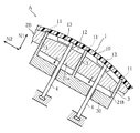
インストルメントパネル1は、たとえば図7に示すような形状を有しており、エアバッグドア部10を備えている。より具体的には、このインストルメントパネル1は、使用に際しては、図8に示すように、その内側に助手席用のエアバッグ装置8が固定して配され、かつこのエアバッグ装置8の正面がエアバッグドア部10とされるものである。エアバッグドア部10は、インストルメントパネル1の他の部分と一体に形成されている。インストルメントパネル1の裏面には、エアバッグ装置8が作動してエアバッグ(図示略)が膨張展開したときに、同図の仮想線に示すように、エアバッグドア部10を破断させて開かせるための複数条の破断用溝11が形成されている。エアバッグドア部10の裏面には、複数のリブ13が形成されており、エアバッグ装置8の筐体に一端が固定された複数のリテーナ80の他端がそれら複数のリブ13に接合されている。これら複数のリテーナ80は、エアバッグ装置8が作動してエアバッグドア部10が開いたときにこのエアバッグドア部10を支持することにより、エアバッグドア部10が車室内に飛散しないようにするためのものである。
【0021】
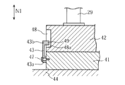
図1によく表われているように、本実施形態の樹脂成形装置Aは、上記したインストルメントパネル1を樹脂成形するための上型2Aおよび下型2Bからなる金型と、下型2Bの一部を構成する可動型としての2つのコア21a,21bを同図の矢印N1方向において昇降させるための往復動装置Bとを備えて構成されている。矢印N1方向が、本願発明でいう第1の方向の一例に相当し、これと直交する矢印N2方向が本願発明でいう第2の方向の一例に相当している。
【0022】
上型2Aおよび下型2Bは、たとえば上型2Aが昇降自在であることにより互いに接近および離反が自在である。これらは、図1および図2に示すように型締めされたときにインストルメントパネル1を成形するためのキャビティ20を形成可能である。この樹脂成形装置Aは、インストルメントパネル1の破断用溝11を形成するための手段として、キャビティ20内に先端部が進入する複数の溝形成刃3を備えている。これら複数の溝形成刃3は、金属製のプレート状であり、かつ複数の破断用溝11の形状に対応した平面視矩形状に繋がっている。これら複数の溝形成刃3の基端部どうしは、連結部材30を介して繋がっている。複数の溝形成刃3は、固定状態に設けられていてもよいが、好ましくは往復動シリンダ(図示略)などによって矢印N1方向に往復動自在とされている。このように複数の溝形成刃3を往復動自在とすれば、キャビティ20内に溶融樹脂を充填するときには各溝形成刃3の先端部をキャビティ20から退出させておくことによりキャビティ20の各部への樹脂の流動を円滑にするとともに、キャビティ20への樹脂の充填が終了してからこの樹脂が硬化するまでの間に溝形成刃3の先端部をキャビティ20内に進入させることによって、インストルメントパネル1に破断用溝11を適切に形成することができる。
【0023】
下型2Bのコア21a,21bは、エアバッグドア部10の片面12を形成するための部分である。これらのコア21a,21bは、下型2Bの他の部分とは別体に形成され、かつその周囲は複数の溝形成刃3によって囲まれている。この樹脂成形装置Aにおいては、図2に示すように、これらのコア21a,21bと連結部材30とを貫通してインストルメントパネル1に当接する複数の支持ロッド4も備えている。これら複数の支持ロッド4は、固定して設けられており、後述するように、インストルメントパネル1の成形後にコア21a,21bを下降させるときに破断用溝11の形成箇所に損傷などを生じさせないようにするのに役立つ。コア21a,21bには、複数のリブ13を形成するための複数の凹部22が設けられており、その配列はたとえば図3に示すようになっている。複数の支持ロッド4の配列も、同図に示すようになっている。
【0024】
図1において、往復動装置Bは、往復動シリンダ40、駆動ブロック41、従動ブロック42、補助部材43、および支持部44を具備して構成されている。駆動ブロック41および従動ブロック42は、コア21a,21bや連結部材30の下方に配されており、コア21a,21bは、複数の連結杆29を介して従動ブロック42に連結支持されている。
【0025】
往復動シリンダ40は、たとえば油圧式のものであり、駆動ブロック41は、この往復動シリンダ40のロッド40aに連結されていることにより、支持部44の表面上をスライドして矢印N2方向に往復動自在である。支持部44としては、駆動ブロック41を支持して矢印N2方向への往復動を許容する機能を果たすものであれば、種々の部材を利用して形成することが可能であり、たとえば樹脂成形用の金型の一部、あるいは金型を支持する適当な部材を支持部44とすることもできる。
【0026】
従動ブロック42および駆動ブロック41は、矢印N1方向において互いに対向し、かつ接触している。駆動ブロック41の上面部は、この駆動ブロック41の厚み方向に段差を有する階段状に形成されており、この部分には複数のカム面45aと複数の受圧面46aとが矢印N2方向において交互に形成されている。従動ブロック42の下面部も、駆動ブロック41の上面部に対応した階段状に形成されており、この部分には複数のカム面45bと複数の平面46bとが交互に形成されている。
【0027】
各カム面45aは、駆動ブロック41が図1の矢印N2aで示す方向に前進するときに従動ブロック42を上昇可能とする面であり、矢印N2方向に対してたとえば45度程度の傾斜角を有する傾斜面として形成されている。各カム面45bもそれと平行または略平行な傾斜面とされている。複数の受圧面46aは、従動ブロック42の昇降を停止させているときにこの従動ブロック42からの荷重を受けるための面であり、矢印N2方向に対する傾斜角がゼロまたは略ゼロの平面として形成されている。各平面46bは、各受圧面46aに平行または略平行である。この往復動装置Bにおいては、複数の受圧面46aと複数の平面46bとが当接し合う第1の態勢と、複数のカム面45a,45bどうしが当接し合う第2の態勢との設定が、駆動ブロック41の矢印N2方向への往復動により切り替え自在となっている。従動ブロック42の矢印N2方向への移動は規制されている。
【0028】
補助部材43は、従動ブロック42に下降力を付与するためのものであり、図4に示すように、この補助部材43の一端部43aは駆動ブロック41に軸47を介して回転可能に取り付けられている。補助部材43の他端部43bには、従動ブロック42の側面に形成された凹部48に係入した突起状の係合部49が形成されている。凹部48は、図1に表われているように係合部49に矢印N1,N2方向への適度な遊びをもたせる形状およびサイズに形成されている。駆動ブロック41が矢印N2b方向に一定量以上後退するときには、凹部48を規定する壁面48aに係合部49が係合し、このことにより補助部材43は従動ブロック42を引っ張って下降させることが可能となっている。
【0029】
次に、往復動装置Bおよびこれを備えた樹脂成形装置Aの作用について説明する。
【0030】
まず、図1および図2に示すように、上型2Aおよび下型2Bにより形成されたキャビティ20内に樹脂を充填してインストルメントパネル1を成形するときには、図1に示すように、駆動ブロック41の各受圧面46aと従動ブロック42の各平面46bとを互いに当接させておく。このように設定しておけば、従動ブロック42の下降(退動)が阻止されるために、キャビティ20内の圧力によってコア21a,21bが不当に押し下げられないようにすることができる。各受圧面46aは矢印N2方向に対して傾斜のない面、あるいは傾斜が殆ど無い面であるために、各受圧面46aにおいては、従動ブロック42から受ける押圧力Fに矢印N2方向の大きな分力が生じないようにし、この押圧力Fの全部または略全部を支持部44により負担させることが可能となる。このようなことにより、押圧力Fが往復動シリンダ40に直接作用することが回避され、往復動シリンダ40の負担軽減による小型化を達成することができる。また、押圧力Fは、複数の受圧面46aのそれぞれに分散させて負担させることができるために、耐荷重性にも優れる。
【0031】
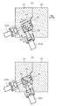
インストルメントパネル1の樹脂成形後に、このインストルメントパネル1を取り出すには、上型2Aを上昇させて金型を開いてから、往復動装置Bを駆動させることにより、図5および図6に示すように、下型2Bのコア21a,21bを矢印N1方向において下降(退動)させる。このようにすれば、次のような利点が得られる。すなわち、コア21a,21bの凹部22とリブ13とは樹脂成形時に嵌合していることによりこれらの密着力が強いために、図示されていない押出ピンなどを利用していきなりインストルメントパネル1のエアバッグドア部10以外の部分を上方に押圧したのでは、エアバッグドア部10がコア21a,21bに密着したままインストルメントパネル1の他の部分のみが押し出される虞れがある。このような事態が生じると、インストルメントパネル1の破断用溝11の形成部分が折れ曲がって損傷する。これに対し、上記したようにコア21a,21bを先に下降させておけば、そのような虞れを回避することが可能である。コア21a,21bの下降時には、図6に示すように、複数の支持ロッド4がエアバッグドア部10に当接していることにより、エアバッグドア部10がコア21a,21bに伴って下降することが阻止されるため、破断用溝11の形成部分に大きな応力を生じさせることなく、コア21a,21bをエアバッグドア部10から適切に離反させることが可能である。
【0032】
上記したコア21a,21bの下降動作は、駆動ブロック41を図5の矢印N2b方向に後退させて、従動ブロック42を下降させることにより行なう。従動ブロック42の下降自体は、重力によりなされる。したがって、コア21a,21bとインストルメントパネル1との密着力が強い場合には、従動ブロック42を重力によって下降させることが困難となる場合もある。これに対し、この往復動装置Bにおいては、既述したとおり、駆動ブロック41が上記矢印N2b方向へ後退したときには、補助部材43が従動ブロック42を引っ張り、強制的に下降させる。このため、コア21a,21bの下降動作の確実化も図られる。
【0033】
コア21a,21bを下降させてから、インストルメントパネル1を下型2Bから取り出した後には、再度の樹脂成形を開始する。この樹脂成形に際しては、コア21a,21bを元の位置に上昇復帰させるが、この動作は、往復動シリンダ40を作動させて駆動ブロック41を矢印N2a方向に適当量だけ前進させることにより行なうことができる。駆動ブロック41が前進すると、傾斜状のカム面45a,45bどうしが摺接する作用によって従動ブロック42が上昇する。この上昇時においても、複数のカム面45a,45bどうしが同時に摺接し合うために、耐荷重性に優れたものにすることができる。
【0034】
このように、この往復動装置Bにおいては、1つの往復動シリンダ40を利用して駆動ブロック41を往復動させるだけで、従動ブロック42およびコア21a,21bの昇降(進退)動作ならびにこの昇降動作の停止時における固定保持、とくに往復動シリンダ40への荷重を軽減することができる固定保持を図ることができる。したがって、本実施形態の往復動装置Bおよび樹脂成形装置Aは、2つの往復動シリンダを用いねばならなかった従来技術と比較すると、その構造が簡素となる。また、往復動シリンダの制御も容易となり、さらには動作の迅速性にも優れたものとなる。
【0035】
本願発明は、上述した実施形態に限定されない。本願発明に係る樹脂成形装置の各部の具体的な構成は、種々に設計変更自在である。
【0036】
たとえば、従動ブロックを第1の方向に往復動させるための手段としては、従動ブロックと駆動ブロックとのそれぞれにカム面を設けることが動作の円滑化などの観点から好ましいが、従動ブロックと駆動ブロックとのいずれか一方のみに傾斜状のカム面を設け、かつこのカム面には他方の非傾斜面状の部分を当接させる構成とした場合にも、従動ブロックを移動させることが可能であり、このような構成にすることもできる。また、カム面や受圧面は、それぞれ複数ずつ設けることが耐荷重性を良好にする上で好ましいものの、やはりそれらの具体的な数も限定されない。駆動源としては、油圧式の往復動シリンダに限らず、他の種類の往復動シリンダやリニアモータなどを用いることもできる。本願発明に係る往復動装置は、樹脂成形装置の成形用型を往復動させる用途に限らず、他の種々の用途に用いることが可能である。
【0037】
本願発明に係る樹脂成形装置は、インストルメントパネルを成形するものに限らない。また、本願発明においては、動作対象となる成形用型を従動ブロックに連結させる構成に代えて、動作対象となる成形用型を駆動ブロックに直接当接させることにより、この成形用型をそのまま本願発明でいう従動ブロックとした構成とすることもできる。このような構成によれば、部品点数の削減により、装置全体の製造コストをより低減することができる。
【図面の簡単な説明】
【図1】本願発明に係る往復動装置を備えた樹脂成形装置の一例を示す要部断面図である。
【図2】図1に示す樹脂成形装置の図1の断面部分とは異なる部分の断面図である。
【図3】図1および図2に示す樹脂成形装置の下型の要部平面図である。
【図4】図1のIV−IV断面図である。
【図5】図1および図2に示す樹脂成形装置の動作を示す要部断面図である。
【図6】図1および図2に示す樹脂成形装置の動作を示す要部断面図である。
【図7】インストルメントパネルの一例を示す斜視図である。
【図8】図7のVIII −VIII 断面図である。
【図9】(a),(b)は、従来技術の一例を示す要部断面図である。
【符号の説明】
A 樹脂成形装置
B 往復動装置
1 インストルメントパネル
2A 上型(成形用型)
2B 下型(成形用型)
20 キャビティ
21a,21b コア
40 往復動シリンダ(駆動源)
41 駆動ブロック
42 従動ブロック
43 補助部材
44 支持部
45a,45b カム面
46a 受圧面
46b 平面
49 係合部[0001]
BACKGROUND OF THE INVENTION
The present invention relates to a resin molding apparatus having a reciprocating DoSo location used the desired operation object to reciprocate.
[0002]
[Prior art]
Conventionally, as a reciprocating device for reciprocating a resin molding die in a resin molding device, there is a structure as shown in FIG. 9 (see, for example, Patent Document 1).
[0003]
[Patent Document 1]
JP-A-11-34124 [0004]
The reciprocating device shown in FIG. 9 is provided by being incorporated in a resin molding apparatus provided with
[0005]
In this reciprocating device, as shown in FIG. 4B, when the resin is filled into the
[0006]
[Problems to be solved by the invention]
However, in the above prior art, in addition to the reciprocating
[0007]
The invention of the present application has been conceived under such circumstances, and includes a reciprocating device that has a small number of parts of a driving device, is easy to control operation, and is excellent in speediness, and the same. An object of the present invention is to provide a resin molding apparatus.
[0008]
DISCLOSURE OF THE INVENTION
In order to solve the above problems, the present invention takes the following technical means.
[0009]
Resin molding apparatus which is herein onset Ming Thus provided, a mold for forming a cavity for resin molding, a portion of the mold and a reciprocating device for advancing and retracting movement toward the cavity a resin molding apparatus comprising, the reciprocating device includes a follower block for forwardly and backwardly moving in a first direction, a driving block which abuts on the driven block, a support portion for supporting the drive block, the the drive block has a drive source for reciprocating in a second direction crossing the first direction while being supported by the support portion, at least one of the drive block and the driven block, the driven block by movement of the drive block has inclined cam surfaces against movably the second direction is provided to the first direction, to the drive block , Than the cam surfaces are pressure-receiving surface inclination is small formation on the second direction, a first posture in which the drive block and the driven block abuts in the pressure-receiving surface, the contacting in the
[0010]
According to such a configuration, when the first position is set, the driven block can be supported by the drive block and locked so as not to move in the first direction. The driven block is locked in a state where the pressure receiving surface of the drive block is in contact with the driven block, because the pressure receiving surface is less inclined with respect to the second direction than the cam surface. In addition, most of the force acting on the pressure receiving surface can be supported by the support portion so that a large load does not act on the drive source. Therefore, it is suitable for avoiding an increase in the size of the drive source. On the other hand, when the drive block is moved in the second direction while the second posture is maintained, the cam surface is an inclined surface, so that the driven block is moved along the inclined surface. The effect of guiding in the direction of 1 is exhibited and the driven block moves. As a result, the driven block can be moved back and forth in the first direction. Further, according to such a configuration, when the drive block is moved, the driven block can be retracted in the first direction only by moving the cam surface in a predetermined direction in the second direction. Even if a situation that cannot be performed occurs, the driven block can be forcibly retracted in the first direction by utilizing the engaging action of the auxiliary member.
[0011]
The switching setting between the reciprocating movement and the locking of the driven block as described above is performed by reciprocating the driving block by the driving source. Therefore, unlike the prior art, it is not necessary to use a plurality of drive sources. As a result, it is possible to reduce the size and cost of the entire apparatus. In addition, the speed of operation is excellent.
[0012]
In a preferred embodiment of the present invention, the pressure-receiving surface is a plane whose inclination angle with respect to the second direction is zero or substantially zero. According to such a configuration, the force received by the drive block from the driven block is more efficiently borne by the support portion, which is more suitable for reducing the load acting on the drive source.
[0013]
In a preferred embodiment of the present invention, a plurality of the cam surfaces are provided on the drive block and the driven block so as to be in contact with each other, and a plurality of the pressure receiving surfaces are provided on the drive block, The driven block is provided with a plurality of flat surfaces that can come into contact with the plurality of pressure receiving surfaces. According to such a configuration, when the driven block is moved in the first direction, the cam surfaces of the driven block and the drive block come into contact with each other, so that the moving operation of the driven block is smoothed. Is planned. In addition, since a plurality of these cam surfaces are provided, the load resistance can be improved. Similarly, when the driven block is fixed, the load resistance can be improved by bringing the plurality of pressure receiving surfaces and the plurality of flat surfaces into contact with each other.
[0017]
Other features and advantages of the present invention will become more apparent from the following description of embodiments of the invention.
[0018]
DETAILED DESCRIPTION OF THE INVENTION
Hereinafter, a preferred embodiment of the present invention will be specifically described with reference to the drawings.
[0019]
Figures 1-6 illustrates an example of engaging Ru tree fat forming apparatus to the present invention, the resin molding apparatus comprises a reciprocating device. The resin molding apparatus A of this embodiment is configured as a resin molding of an
[0020]
The
[0021]
As clearly shown in FIG. 1, the resin molding apparatus A of this embodiment includes a mold composed of an
[0022]
The
[0023]
The
[0024]
In FIG. 1, the reciprocating device B includes a
[0025]
The
[0026]
The driven
[0027]
Each
[0028]
The
[0029]
Next, the operation of the reciprocating device B and the resin molding device A including the same will be described.
[0030]
First, as shown in FIGS. 1 and 2, when the
[0031]
In order to take out the
[0032]
The above-described lowering operation of the
[0033]
After lowering the
[0034]
As described above, in this reciprocating device B, by merely reciprocating the
[0035]
The present invention is not limited to the embodiment described above. The specific structure of each part of the engagement Ru tree fat forming apparatus to the present invention, be varied in many ways.
[0036]
For example, as a means for reciprocating the driven block in the first direction, it is preferable to provide a cam surface on each of the driven block and the drive block from the viewpoint of smoothing the operation. It is possible to move the follower block even when an inclined cam surface is provided on only one of them and the other non-inclined surface portion is in contact with this cam surface. Such a configuration can also be adopted. Moreover, although it is preferable to provide a plurality of cam surfaces and pressure receiving surfaces, respectively, in order to improve the load resistance, the specific number thereof is not limited. The drive source is not limited to a hydraulic reciprocating cylinder, and other types of reciprocating cylinders, linear motors, and the like can also be used. The reciprocating device according to the present invention is not limited to the use of reciprocating the molding die of the resin molding device, but can be used for various other purposes.
[0037]
The resin molding apparatus according to the present invention is not limited to molding an instrument panel. In the invention of the present application, instead of the configuration in which the molding die to be operated is connected to the driven block, the molding die to be operated is directly brought into contact with the drive block so that the molding die is directly applied to the present application. It can also be set as the driven block said by invention. According to such a configuration, the manufacturing cost of the entire apparatus can be further reduced by reducing the number of parts.
[Brief description of the drawings]
FIG. 1 is a cross-sectional view of an essential part showing an example of a resin molding apparatus provided with a reciprocating device according to the present invention.
2 is a cross-sectional view of a portion different from the cross-sectional portion of FIG. 1 of the resin molding apparatus shown in FIG.
3 is a plan view of the main part of the lower mold of the resin molding apparatus shown in FIGS. 1 and 2. FIG.
4 is a cross-sectional view taken along the line IV-IV in FIG.
5 is a cross-sectional view of a principal part showing the operation of the resin molding apparatus shown in FIGS. 1 and 2. FIG.
6 is a cross-sectional view of a principal part showing the operation of the resin molding apparatus shown in FIGS. 1 and 2. FIG.
FIG. 7 is a perspective view showing an example of an instrument panel.
8 is a cross-sectional view taken along line VIII-VIII in FIG.
FIGS. 9A and 9B are cross-sectional views of relevant parts showing an example of a conventional technique. FIGS.
[Explanation of symbols]
A Resin molding device
2B Lower mold (molding mold)
20
41
Claims (3)
上記往復動装置は、第1の方向において進退動させるための従動ブロックと、この従動ブロックに当接する駆動ブロックと、この駆動ブロックを支持する支持部と、上記駆動ブロックを上記支持部に支持させたまま上記第1の方向と交差する第2の方向に往復動させる駆動源と、を有しており、
上記駆動ブロックおよび上記従動ブロックの少なくとも一方には、上記駆動ブロックの移動によって上記従動ブロックが上記第1の方向に移動可能に上記第2の方向に対して傾斜したカム面が設けられており、
上記駆動ブロックには、上記カム面よりも上記第2の方向に対する傾きが小さい受圧面が形成されており、
上記駆動ブロックおよび上記従動ブロックが上記受圧面において当接する第1の態勢と、上記カム面において当接する第2の態勢とを、上記駆動ブロックの往復動により切り替え自在であり、かつ、
上記駆動ブロックと上記従動ブロックとは、一部分において上記駆動ブロックに対して回動可能に連結されているとともに、他の一部分が上記従動ブロックの側面に設けた凹部に対して上記第1の方向および上記第2の方向へ所定の遊びをもって係合する補助部材によって連携されていることにより、上記駆動ブロックが上記第2の方向における所定方向に移動したとき、上記従動ブロックは上記第1の方向において強制退動することを特徴とする、樹脂成形装置。 A resin molding apparatus comprising: a molding die for forming a resin molding cavity; and a reciprocating device for moving a part of the molding die forward and backward toward the cavity,
The reciprocating device includes a driven block for advancing and retreating in a first direction, a drive block that contacts the driven block, a support portion that supports the drive block, and a support block that supports the drive block. And a drive source that reciprocates in a second direction that intersects the first direction ,
At least one of the drive block and the driven block is provided with a cam surface inclined with respect to the second direction so that the driven block can move in the first direction by the movement of the drive block .
The drive block is formed with a pressure receiving surface having a smaller inclination with respect to the second direction than the cam surface ,
The drive block and the driven block can be switched between a first posture where the pressure receiving surface abuts and a second posture where the drive block abuts on the cam surface by reciprocation of the drive block , and
The drive block and the driven block are partially connected to the drive block in a rotatable manner, and the other part is in the first direction with respect to the recess provided on the side surface of the driven block. When the drive block moves in a predetermined direction in the second direction, the driven block is moved in the first direction by being linked by an auxiliary member that engages with the predetermined play in the second direction. wherein the forced retracted to Rukoto, resin molding apparatus.
上記受圧面は、上記駆動ブロックに複数設けられ、かつ上記従動ブロックには、それら複数の受圧面に対して接触可能な複数の平面が設けられている、請求項1または2に記載の樹脂成形装置。A plurality of the cam surfaces are provided on each of the drive block and the driven block so as to be in contact with each other,
The resin molding according to claim 1 or 2, wherein a plurality of the pressure receiving surfaces are provided on the drive block, and the driven block is provided with a plurality of flat surfaces capable of contacting the plurality of pressure receiving surfaces. Equipment .
Priority Applications (8)
| Application Number | Priority Date | Filing Date | Title |
|---|---|---|---|
| JP2002286496A JP3889692B2 (en) | 2002-09-30 | 2002-09-30 | Resin molding equipment |
| KR1020057005370A KR100716432B1 (en) | 2002-09-30 | 2003-09-26 | Air bag cover body forming apparatus |
| EP03799146.0A EP1555107B1 (en) | 2002-09-30 | 2003-09-26 | Air bag cover body forming apparatus |
| AU2003266660A AU2003266660A1 (en) | 2002-09-30 | 2003-09-26 | Air bag cover body forming apparatus |
| CN038227460A CN1684810B (en) | 2002-09-30 | 2003-09-26 | Airbag cover forming device |
| PCT/JP2003/012375 WO2004030892A1 (en) | 2002-09-30 | 2003-09-26 | Air bag cover body forming apparatus |
| US10/528,594 US7338279B2 (en) | 2002-09-30 | 2003-09-26 | Air bag cover body forming apparatus |
| CA002500561A CA2500561C (en) | 2002-09-30 | 2003-09-26 | Air bag cover forming apparatus |
Applications Claiming Priority (1)
| Application Number | Priority Date | Filing Date | Title |
|---|---|---|---|
| JP2002286496A JP3889692B2 (en) | 2002-09-30 | 2002-09-30 | Resin molding equipment |
Publications (2)
| Publication Number | Publication Date |
|---|---|
| JP2004122412A JP2004122412A (en) | 2004-04-22 |
| JP3889692B2 true JP3889692B2 (en) | 2007-03-07 |
Family
ID=32279530
Family Applications (1)
| Application Number | Title | Priority Date | Filing Date |
|---|---|---|---|
| JP2002286496A Expired - Fee Related JP3889692B2 (en) | 2002-09-30 | 2002-09-30 | Resin molding equipment |
Country Status (1)
| Country | Link |
|---|---|
| JP (1) | JP3889692B2 (en) |
Families Citing this family (2)
| Publication number | Priority date | Publication date | Assignee | Title |
|---|---|---|---|---|
| KR100812835B1 (en) * | 2006-12-06 | 2008-03-11 | 현대자동차주식회사 | Vehicle front passenger's airbag and manufacturing method |
| CN107351328B (en) * | 2017-08-07 | 2023-05-12 | 宁波建林模具有限公司 | Mould for lower decorative plate of automobile back door |
-
2002
- 2002-09-30 JP JP2002286496A patent/JP3889692B2/en not_active Expired - Fee Related
Also Published As
| Publication number | Publication date |
|---|---|
| JP2004122412A (en) | 2004-04-22 |
Similar Documents
| Publication | Publication Date | Title |
|---|---|---|
| US20130340968A1 (en) | Die cast casting apparatus and method for releasing casting from mold | |
| CN209937570U (en) | Internal parting mold and demolding mechanism thereof | |
| JP2005231066A (en) | Molding machine and mold opening method | |
| US7267157B2 (en) | Molding and transporting apparatus and method therefor | |
| JP3889692B2 (en) | Resin molding equipment | |
| CN214026920U (en) | Composite slide block arc core-pulling demoulding device | |
| JP2010274490A (en) | Mold for molding | |
| CN219357935U (en) | Vertical powder forming equipment | |
| JP2003025401A (en) | Mold clamping linking device in mold clamping device | |
| CN109910248B (en) | Internal-dividing die and demolding mechanism thereof | |
| CN109648807B (en) | Pushing mechanism and injection molding machine | |
| CN113441622A (en) | Die device | |
| JP2010110800A (en) | Die casting mold and die casting method | |
| JP3755440B2 (en) | Injection mold and method for producing molded article using the same | |
| CN220534694U (en) | Slide block inner inclined ejection mechanism in die device and die device | |
| JP2007196572A (en) | Molding equipment | |
| CN215095270U (en) | Injection molding machine | |
| JP4498526B2 (en) | Powder forming press | |
| CN214867164U (en) | Multifunctional vertical extrusion casting machine | |
| CN111546582B (en) | Tunnel core-pulling mechanism | |
| JP2003205531A (en) | Mold | |
| JP6709875B1 (en) | Molding machine | |
| JP2004243381A (en) | Casting die structure and casting equipment using the same | |
| JP4410192B2 (en) | Injection molding machine | |
| JP3889693B2 (en) | Airbag cover body forming apparatus |
Legal Events
| Date | Code | Title | Description |
|---|---|---|---|
| A621 | Written request for application examination |
Free format text: JAPANESE INTERMEDIATE CODE: A621 Effective date: 20050608 |
|
| A131 | Notification of reasons for refusal |
Free format text: JAPANESE INTERMEDIATE CODE: A131 Effective date: 20060822 |
|
| A521 | Written amendment |
Free format text: JAPANESE INTERMEDIATE CODE: A523 Effective date: 20061017 |
|
| TRDD | Decision of grant or rejection written | ||
| A01 | Written decision to grant a patent or to grant a registration (utility model) |
Free format text: JAPANESE INTERMEDIATE CODE: A01 Effective date: 20061128 |
|
| A61 | First payment of annual fees (during grant procedure) |
Free format text: JAPANESE INTERMEDIATE CODE: A61 Effective date: 20061130 |
|
| R150 | Certificate of patent or registration of utility model |
Free format text: JAPANESE INTERMEDIATE CODE: R150 |
|
| FPAY | Renewal fee payment (event date is renewal date of database) |
Free format text: PAYMENT UNTIL: 20101208 Year of fee payment: 4 |
|
| FPAY | Renewal fee payment (event date is renewal date of database) |
Free format text: PAYMENT UNTIL: 20111208 Year of fee payment: 5 |
|
| FPAY | Renewal fee payment (event date is renewal date of database) |
Free format text: PAYMENT UNTIL: 20111208 Year of fee payment: 5 |
|
| FPAY | Renewal fee payment (event date is renewal date of database) |
Free format text: PAYMENT UNTIL: 20121208 Year of fee payment: 6 |
|
| FPAY | Renewal fee payment (event date is renewal date of database) |
Free format text: PAYMENT UNTIL: 20121208 Year of fee payment: 6 |
|
| FPAY | Renewal fee payment (event date is renewal date of database) |
Free format text: PAYMENT UNTIL: 20131208 Year of fee payment: 7 |
|
| LAPS | Cancellation because of no payment of annual fees |