JP3834816B2 - Objective lens unit - Google Patents
Objective lens unit Download PDFInfo
- Publication number
- JP3834816B2 JP3834816B2 JP2003119503A JP2003119503A JP3834816B2 JP 3834816 B2 JP3834816 B2 JP 3834816B2 JP 2003119503 A JP2003119503 A JP 2003119503A JP 2003119503 A JP2003119503 A JP 2003119503A JP 3834816 B2 JP3834816 B2 JP 3834816B2
- Authority
- JP
- Japan
- Prior art keywords
- objective lens
- filling
- adhesive
- passage hole
- filling recess
- Prior art date
- Legal status (The legal status is an assumption and is not a legal conclusion. Google has not performed a legal analysis and makes no representation as to the accuracy of the status listed.)
- Expired - Fee Related
Links
- 239000000853 adhesive Substances 0.000 claims description 58
- 230000001070 adhesive effect Effects 0.000 claims description 58
- 230000002093 peripheral effect Effects 0.000 claims description 6
- 239000000945 filler Substances 0.000 claims description 5
- 230000001678 irradiating effect Effects 0.000 claims description 4
- 230000004075 alteration Effects 0.000 description 7
- 230000008602 contraction Effects 0.000 description 5
- 230000000694 effects Effects 0.000 description 4
- 230000002411 adverse Effects 0.000 description 3
- 238000000034 method Methods 0.000 description 2
- 230000001012 protector Effects 0.000 description 2
- 238000007711 solidification Methods 0.000 description 2
- 230000008023 solidification Effects 0.000 description 2
- 239000003795 chemical substances by application Substances 0.000 description 1
- 230000003287 optical effect Effects 0.000 description 1
Images


Classifications
-
- G—PHYSICS
- G02—OPTICS
- G02B—OPTICAL ELEMENTS, SYSTEMS OR APPARATUS
- G02B7/00—Mountings, adjusting means, or light-tight connections, for optical elements
- G02B7/02—Mountings, adjusting means, or light-tight connections, for optical elements for lenses
- G02B7/025—Mountings, adjusting means, or light-tight connections, for optical elements for lenses using glue
Landscapes
- Physics & Mathematics (AREA)
- General Physics & Mathematics (AREA)
- Optics & Photonics (AREA)
- Optical Head (AREA)
- Moving Of The Head For Recording And Reproducing By Optical Means (AREA)
- Optical Recording Or Reproduction (AREA)
- Lens Barrels (AREA)
Description
【0001】
【発明の属する技術分野】
本発明は、光ピックアップに使用される対物レンズユニットであって、特に、少量の接着剤で対物レンズの固定を確実に行うことができるようにしたものである。
【0002】
【従来の技術】
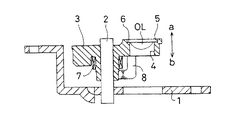
従来、対物レンズユニットの一例として図5及び図6に示すように示すものがある。これは、アクトベース1上のシャフト2に沿ってフォーカス方向a,bに摺動可能で該シャフト2回りでトラッキング方向c,dに揺動可能なホルダ3の先端部に光通過孔4が貫設され、該光通過孔4の一端部にその光通過孔4よりも大径の嵌合溝5を同心状に形成することにより、前記光通過孔4の内周面にレンズ受座6が形成され、その光通過孔4に嵌入させた対物レンズOLがレンズ受座6上に載置されてホルダ3に固定されている。なお、7はフォーカスコイル、8はトラッキングコイル、9はマグネットである。
【0003】
上記構成において、フォーカスコイル7に通電して励磁させることにより、ホルダ3をシャフト2に沿ってフォーカス方向a,bに摺動させて、対物レンズOLの焦点をディスク(図示せず)に合わせ、トラッキングコイル8に通電して励磁させることにより、ホルダ3をシャフト2回りでトラッキング方向c,dに揺動させて、対物レンズOLをディスクの所定のトラックに追従させる。
【0004】
前記対物レンズOLをホルダ3に固定する技術の一例として特許文献1に記載したものがある。これは、図7及び図8に示すように、前記嵌合溝5の内周面に、底面11aを略水平状態とし内側面11b〜11dを略垂直状態とした2つの矩形状充填凹部11が180°の対向角度をおいて形成されており、光通過孔4に嵌入した対物レンズOLをレンズ受座6上に載置し、図9(a)及び(b)に示すように、接着剤充填器のノズル12から前記各充填凹部11内に紫外線硬化性接着剤UVを充填し、紫外線を照射して接着剤UVを固化させることにより、対物レンズOLをホルダ3に固定するものである。
【0005】
【特許文献1】
特開平11−110800号公報
【0006】
【発明が解決しようとする課題】
上記従来の構成では、充填凹部11が矩形箱状の空間からなり、対物レンズOLに対向する開口部11eの面積の割りには容積が比較的大きいため、該充填凹部11内に接着剤UVを充分に充填すると、その充填した接着剤UVの固化収縮により、対物レンズOLに歪みや収差が生じるおそれがある。
【0007】
また、前記充填凹部11の底面11aが略水平状態に形成されているため、その底面11aに沿って充填した接着剤UVを対物レンズOL側に積極的に流動させる機能が無く、その充填した接着剤UVと対物レンズOLとの接触が不確実になるおそれもある。
【0008】
更に、底面11aと各内側面11b〜11dとの間に角形のコーナ部があるため、接着剤UVを充填したときに、充填凹部11内の空気が完全に逃げ切れずに前記コーナ部に溜まって、空気溜まり13を形成することがあり、この空気溜まり13によって、接着剤UVによる接着力が低下すると共に、温度変化により空気溜まり13が拡張収縮されて、対物レンズOLに歪みや収差が生じるおそれがある。
【0009】
しかも、充填凹部11にあてがったノズル12を位置決めするものがないため、図9(b)に仮想線で示すように、ノズル12が光通過孔4の中心Oから充填凹部11の中央を通って延びる中心線Lから側方にずれることがあり、そのずれた間隔αだけノズル12から接着剤UVが偏って充填されるため、その充填した接着剤UVと対物レンズOLとの接触面積が小さくなって、接着不良が生じるおそれがある。
【0010】
本発明は、上記従来の欠点に鑑み、少量の接着剤で対物レンズの固定を確実に行うことができるようにした対物レンズユニットを提供することを目的としている。
【0011】
【課題を解決するための手段】
上記目的を達成するため、請求項1に記載の発明は、アクトベース上のシャフトに沿ってフォーカス方向に摺動可能で該シャフト回りでトラッキング方向に揺動可能なホルダの先端部に光通過孔が貫設され、該光通過孔の一端部にその光通過孔よりも大径の嵌合溝を同心状に形成することにより、前記光通過孔の内周面にレンズ受座が形成され、前記嵌合溝の内周面に周方向所定角度をおいて複数の充填凹部が形成されており、前記光通過孔に嵌入した対物レンズをレンズ受座上に載置し、接着剤充填器のノズルから前記各充填凹部内に紫外線硬化性接着剤を充填し、紫外線を照射して接着剤を固化させることにより、前記対物レンズをホルダに固定するようにした対物レンズユニットにおいて、前記複数の充填凹部の底面をホルダの一端面からレンズ受座に向けて傾斜させることより、その各充填凹部の縦断面形状が略三角形に形成され、前記各充填凹部の底面を挟んで対向する両内側面を円弧状に形成することにより、その各充填凹部の横断面形状が下すぼまりの略U字形に形成され、前記各充填凹部の平面形状を奥すぼまりの略U字形に形成することにより、該各充填凹部の奥端円弧部が光通過孔の中心からその各充填凹部の中央を通って延びる中心線上に形成されていることを特徴としている。
【0012】
上記構成は実施の一形態(図1から図4参照)に対応するものであって、これによれば、各充填凹部の縦断面形状が略三角形に形成されて、その容積が対物レンズに対向する開口部の面積の割りには小さいから、該各充填凹部に対する接着剤の充填量が少量で済み、その少量の接着剤により対物レンズの固定を確実に行うことができると共に、接着剤の固化収縮による対物レンズの歪みや収差による悪影響を極めて小さくすることができる。
【0013】
また、各充填凹部の底面がホルダの一端面からレンズ受座に向けて傾斜されており、その傾斜状底面に沿って充填した接着剤を対物レンズ側に積極的に流動させるから、その充填した接着剤と対物レンズとを確実に接触させて、対物レンズの固定を強固に行うことができる。
【0014】
更に、各充填凹部の円弧状両内側面により該各充填凹部の横断面形状が下すぼまりの略U字形に形成されているから、接着剤を充填したときに各充填凹部内の空気が円弧状両内側面に沿って円滑に逃がされ、その各充填凹部内に従来のように空気溜まりが形成されることが無い。従って、空気溜まりによる接着剤の接着力低下や空気溜まりの温度変化による拡張収縮で対物レンズに歪みや収差が生じるという難点を解消することができる。
【0015】
しかも、各充填凹部の奥端円弧部を該各充填凹部の中央を通る中心線上に形成しているので、その奥端円弧部に接着剤充填器のノズルをあてがうだけで、該ノズルを各充填凹部の中央に向けて不測に移動しないように位置決めすることでき、そのノズルから接着剤を各充填凹部内に偏ることなく充填することにより、その充填した接着剤と対物レンズとの接触面積を大きくとって、接着不良が生じないようにすることができる。
【0016】
【発明の実施の形態】
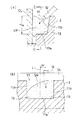
図1から図3は本発明の実施の一形態である対物レンズユニットを示すものであって、嵌合溝5の内周面に4つの充填凹部14が周方向に90°ごとに形成され、図4(a)に示すように、各充填凹部14の底面14aをホルダ3の一端面3aからレンズ受座6に向けて傾斜させることより、その各充填凹部14の縦断面形状が略三角形に形成され、図4(b)に示すように、各充填凹部14の底面14aを挟んで対向する両内側面14b,14cを円弧状に形成することにより、その各充填凹部14の横断面形状が下すぼまりの略U字形に形成され、図4(c)に示すように、各充填凹部14の平面形状を奥すぼまりの略U字形に形成することにより、該各充填凹部14の奥端円弧部14dが光通過孔4の中心Oからその各充填凹部14の中央を通って延びる中心線L上に形成されている(図1参照)。上記以外の構成は図5から図8に示す構成とほぼ同じであるから、同一部分に同一符号を付してその説明を省略する。
【0017】
対物レンズOLの固定手順を説明すると、光通過孔4に嵌入した対物レンズOLをレンズ受座6上に載置した後、接着剤充填器のノズル12を奥端円弧部14dにあてがって、該ノズル12から各充填凹部14内に紫外線硬化性接着剤UVを充填し、紫外線を照射して接着剤UVを固化させることにより、対物レンズOLをホルダ3に固定する。
【0018】
上記構成によれば、図4(a)に示すように、各充填凹部14の縦断面形状が略三角形に形成されて、その容積が対物レンズOLに対向する開口部14eの面積の割りには小さいから、該各充填凹部14に対する接着剤UVの充填量が少量で済み、その少量の接着剤UVにより対物レンズOLの固定を確実に行うことができると共に、接着剤UVの固化収縮による対物レンズOLの歪みや収差による悪影響を極めて小さくすることができる。
【0019】
また、各充填凹部14の底面14aがホルダ3の一端面3aからレンズ受座6に向けて傾斜されており、その傾斜状底面14aに沿って充填した接着剤UVを対物レンズOL側に積極的に流動させるから、その充填した接着剤UVと対物レンズOLとを確実に接触させて、対物レンズOLの固定を強固に行うことができる。
【0020】
更に、図4(b)に示すように、各充填凹部14の円弧状両内側面14b,14cにより該各充填凹部14の横断面形状が下すぼまりの略U字形に形成されているから、接着剤UVを充填したときに各充填凹部14内の空気が円弧状両内側面14b,14cに沿って円滑に逃がされ、その各充填凹部14内に従来のように空気溜まり13(図9参照)が形成されることが無い。従って、空気溜まり13による接着剤UVの接着力低下や温度変化による空気溜まり13の拡張収縮で対物レンズOLに歪みや収差が生じるという難点を解消することができる。
【0021】
しかも、図4(c)に示すように、各充填凹部14の奥端円弧部14dを該各充填凹部14の中央を通る中心線L上に形成しているので、その奥端円弧部14dに接着剤充填器のノズル12をあてがうだけで、該ノズル12を各充填凹部14の中央に向けて不測に移動しないように位置決めすることでき、そのノズル12から接着剤UVを各充填凹部14内に偏ることなく充填することにより、その充填した接着剤UVと対物レンズOLとの接触面積を大きくとって、接着不良が生じないようにすることができる。
【0022】
上記の実施の形態では、充填凹部14に充填した接着剤UVの上面が対物レンズOLの上面とほぼ面一状態になるようにしたが、図2に仮想線で示すように、接着剤UVの上面を対物レンズOLの上面よりも上方に凸状に盛り上げてレンズプロテクタ15を形成してもよく、この場合、レンズプロテクタ15により対物レンズOLがディスク(図示せず)に衝突して損傷されないように保護することができる。
【0023】
【発明の効果】
請求項1に記載の発明によれば、実施の一形態(図1から図4参照)に示すように、各充填凹部の縦断面形状が略三角形に形成されて、その容積が対物レンズに対向する開口部の面積の割りには小さいから、該各充填凹部に対する接着剤の充填量が少量で済み、その少量の接着剤により対物レンズの固定を確実に行うことができると共に、接着剤の固化収縮による対物レンズの歪みや収差による悪影響を極めて小さくすることができる。
【0024】
また、各充填凹部の底面がホルダの一端面からレンズ受座に向けて傾斜されており、その傾斜状底面に沿って充填した接着剤を対物レンズ側に積極的に流動させるから、その充填した接着剤と対物レンズとを確実に接触させて、対物レンズの固定を強固に行うことができる。
【0025】
更に、各充填凹部の円弧状両内側面により該各充填凹部の横断面形状が下すぼまりの略U字形に形成されているから、接着剤を充填したときに各充填凹部内の空気が円弧状両内側面に沿って円滑に逃がされ、その各充填凹部内に従来のように空気溜まりが形成されることが無い。従って、空気溜まりによる接着剤の接着力低下や空気溜まりの温度変化による拡張収縮で対物レンズに歪みや収差が生じるとう難点を解消することができる。
【0026】
しかも、各充填凹部の奥端円弧部を該各充填凹部の中央を通る中心線上に形成しているので、その奥端円弧部に接着剤充填器のノズルをあてがうだけで、該ノズルを各充填凹部の中央に向けて不測に移動しないように位置決めすることでき、そのノズルから接着剤を各充填凹部内に偏ることなく充填することにより、その充填した接着剤と対物レンズとの接触面積を大きくとって、接着不良が生じないようにすることができる。
【図面の簡単な説明】
【図1】 本発明の実施の一形態である対物レンズユニットの要部の平面図である。
【図2】 同要部の縦断面図である。
【図3】 同要部の分解斜視図である。
【図4】 (a)は充填凹部の拡大縦断面図、(b)はA−A矢視図、(c)はB−B矢視図である。
【図5】 対物レンズユニットの縦断面図である。
【図6】 同平面図である。
【図7】 従来例を示す要部の平面図である。
【図8】 同縦断面図である。
【図9】 (a)は同充填凹部の拡大縦断面図、(b)はC−C矢視図である。
【符号の説明】
1 アクトベース
2 シャフト
3 ホルダ
4 光通過孔
5 嵌合溝
6 レンズ受座
12 接着剤充填器のノズル
14 充填凹部
14a 充填凹部の底面
14b 充填凹部の内側面
14c 充填凹部の内側面
14d 充填凹部の奥端円弧部
a,b フォーカス方向
c,d トラッキング方向
OL 対物レンズ
O 光通過孔の中心
L 中心線
UV 紫外線硬化性接着剤[0001]
BACKGROUND OF THE INVENTION
The present invention is an objective lens unit used for an optical pickup, and in particular, the objective lens can be reliably fixed with a small amount of adhesive.
[0002]
[Prior art]
Conventionally, an example of an objective lens unit is shown in FIGS. 5 and 6. This is because the
[0003]
In the above configuration, by energizing and exciting the
[0004]
One example of a technique for fixing the objective lens OL to the
[0005]
[Patent Document 1]
JP-A-11-110800 [0006]
[Problems to be solved by the invention]
In the above conventional configuration, the
[0007]
Further, since the
[0008]
Furthermore, since there is a rectangular corner portion between the
[0009]
Moreover, since there is nothing for positioning the
[0010]
An object of the present invention is to provide an objective lens unit in which the objective lens can be reliably fixed with a small amount of adhesive in view of the above-described conventional drawbacks.
[0011]
[Means for Solving the Problems]
In order to achieve the above-mentioned object, the invention according to
[0012]
The above configuration corresponds to one embodiment (see FIGS. 1 to 4), and according to this, the longitudinal sectional shape of each filling recess is formed in a substantially triangular shape, and its volume faces the objective lens. Since the area of the opening to be opened is small, the filling amount of the adhesive into each filling recess is small, and the objective lens can be securely fixed with the small amount of adhesive and the adhesive is solidified. The adverse effects of distortion and aberration of the objective lens due to contraction can be extremely reduced.
[0013]
In addition, the bottom surface of each filling recess is inclined from one end surface of the holder toward the lens seat, and the adhesive filled along the inclined bottom surface is allowed to actively flow toward the objective lens side. The adhesive lens and the objective lens can be securely brought into contact with each other, and the objective lens can be firmly fixed.
[0014]
Further, since the cross-sectional shape of each filling recess is formed in a substantially U-shaped shape with a concavity by the arc-shaped inner side surfaces of each filling recess, the air in each filling recess is circular when filled with adhesive. It escapes smoothly along both arc-shaped inner side surfaces, and an air pocket is not formed in each filling recess as in the prior art. Therefore, it is possible to eliminate the difficulty that distortion and aberration occur in the objective lens due to a decrease in the adhesive force of the adhesive due to the air pool and expansion and contraction due to a temperature change of the air pool.
[0015]
In addition, since the back end arc portion of each filling recess is formed on the center line passing through the center of each filling recess, the nozzle of each adhesive filling device can be filled only by applying the nozzle of the adhesive filler to the back end arc portion. It can be positioned so that it does not move unexpectedly toward the center of the recess, and the contact area between the filled adhesive and the objective lens is increased by filling the adhesive from the nozzle into each filling recess without bias. Therefore, it is possible to prevent a bonding failure from occurring.
[0016]
DETAILED DESCRIPTION OF THE INVENTION
FIGS. 1 to 3 show an objective lens unit according to an embodiment of the present invention, in which four
[0017]
The procedure for fixing the objective lens OL will be described. After the objective lens OL fitted in the
[0018]
According to the above configuration, as shown in FIG. 4A, the vertical cross-sectional shape of each filling
[0019]
Further, the
[0020]
Further, as shown in FIG. 4 (b), the arc-shaped inner side surfaces 14b, 14c of each filling
[0021]
Moreover, as shown in FIG. 4C, the back
[0022]
In the above embodiment, the upper surface of the adhesive UV filled in the filling
[0023]
【The invention's effect】
According to the first aspect of the present invention, as shown in one embodiment (see FIGS. 1 to 4), the longitudinal sectional shape of each filling recess is formed in a substantially triangular shape, and the volume thereof faces the objective lens. Since the area of the opening to be opened is small, the filling amount of the adhesive into each filling recess is small, and the objective lens can be securely fixed with the small amount of adhesive and the adhesive is solidified. The adverse effects of distortion and aberration of the objective lens due to contraction can be extremely reduced.
[0024]
In addition, the bottom surface of each filling recess is inclined from one end surface of the holder toward the lens seat, and the adhesive filled along the inclined bottom surface is allowed to actively flow toward the objective lens side. The adhesive lens and the objective lens can be securely brought into contact with each other, and the objective lens can be firmly fixed.
[0025]
Further, since the cross-sectional shape of each filling recess is formed in a substantially U-shaped shape with a concavity by the arc-shaped inner side surfaces of each filling recess, the air in each filling recess is circular when filled with adhesive. It escapes smoothly along both arc-shaped inner side surfaces, and an air pocket is not formed in each filling recess as in the prior art. Therefore, it is possible to eliminate the difficulty that distortion and aberration occur in the objective lens due to the adhesive force reduction due to the air pool and the expansion and contraction due to the temperature change of the air pool.
[0026]
In addition, since the back end arc portion of each filling recess is formed on the center line passing through the center of each filling recess, the nozzle of each adhesive filling device can be filled only by applying the nozzle of the adhesive filler to the back end arc portion. It can be positioned so that it does not move unexpectedly toward the center of the recess, and the contact area between the filled adhesive and the objective lens is increased by filling the adhesive from the nozzle into each filling recess without bias. Therefore, it is possible to prevent a bonding failure from occurring.
[Brief description of the drawings]
FIG. 1 is a plan view of a main part of an objective lens unit according to an embodiment of the present invention.
FIG. 2 is a longitudinal sectional view of the main part.
FIG. 3 is an exploded perspective view of the main part.
4A is an enlarged longitudinal sectional view of a filling recess, FIG. 4B is an AA arrow view, and FIG. 4C is a BB arrow view.
FIG. 5 is a longitudinal sectional view of an objective lens unit.
FIG. 6 is a plan view of the same.
FIG. 7 is a plan view of a main part showing a conventional example.
FIG. 8 is a longitudinal sectional view of the same.
FIG. 9A is an enlarged longitudinal sectional view of the filling recess, and FIG. 9B is a CC arrow view.
[Explanation of symbols]
Claims (1)
Priority Applications (2)
| Application Number | Priority Date | Filing Date | Title |
|---|---|---|---|
| JP2003119503A JP3834816B2 (en) | 2003-04-24 | 2003-04-24 | Objective lens unit |
| US10/830,219 US6885511B2 (en) | 2003-04-24 | 2004-04-23 | Object lens unit |
Applications Claiming Priority (1)
| Application Number | Priority Date | Filing Date | Title |
|---|---|---|---|
| JP2003119503A JP3834816B2 (en) | 2003-04-24 | 2003-04-24 | Objective lens unit |
Publications (2)
| Publication Number | Publication Date |
|---|---|
| JP2004326912A JP2004326912A (en) | 2004-11-18 |
| JP3834816B2 true JP3834816B2 (en) | 2006-10-18 |
Family
ID=33296435
Family Applications (1)
| Application Number | Title | Priority Date | Filing Date |
|---|---|---|---|
| JP2003119503A Expired - Fee Related JP3834816B2 (en) | 2003-04-24 | 2003-04-24 | Objective lens unit |
Country Status (2)
| Country | Link |
|---|---|
| US (1) | US6885511B2 (en) |
| JP (1) | JP3834816B2 (en) |
Families Citing this family (16)
| Publication number | Priority date | Publication date | Assignee | Title |
|---|---|---|---|---|
| US20060078638A1 (en) * | 2004-10-08 | 2006-04-13 | 3D Systems, Inc. | Stereolithographic apparatus |
| DE102005013069A1 (en) * | 2005-03-18 | 2006-09-28 | Deutsche Thomson-Brandt Gmbh | Scanner for optical storage media |
| US7690909B2 (en) * | 2005-09-30 | 2010-04-06 | 3D Systems, Inc. | Rapid prototyping and manufacturing system and method |
| JP4524272B2 (en) * | 2006-08-03 | 2010-08-11 | 株式会社日立メディアエレクトロニクス | Optical pickup |
| JP2008097746A (en) * | 2006-10-13 | 2008-04-24 | Ntn Corp | Lens holder, lens protection member and its forming method |
| JP2008111932A (en) * | 2006-10-30 | 2008-05-15 | Nidec Copal Corp | Lens barrel |
| JP2009258557A (en) * | 2008-04-21 | 2009-11-05 | Funai Electric Co Ltd | Imaging apparatus |
| CN102645717A (en) * | 2011-02-17 | 2012-08-22 | 一诠精密工业股份有限公司 | The method of using UV glue to fix the optical lens |
| JP6101508B2 (en) * | 2013-02-18 | 2017-03-22 | 株式会社日立メディアエレクトロニクス | Optical component bonding structure, manufacturing method, and video output apparatus |
| CN103217225A (en) * | 2013-03-18 | 2013-07-24 | 中国科学院长春光学精密机械与物理研究所 | Supporting structure of point diffraction interferometer small hole plate |
| DE102014215105A1 (en) | 2014-07-31 | 2016-02-04 | Forschungsverbund Berlin E.V. | An optical device comprising a micro-optic and a holder and method of manufacturing an optical device |
| WO2019026450A1 (en) * | 2017-07-31 | 2019-02-07 | 日本電産株式会社 | Light blocking blade, blade driving device, and imaging device |
| JPWO2019026448A1 (en) * | 2017-07-31 | 2020-08-27 | 日本電産株式会社 | Shading blade, blade driving device, and imaging device |
| CN110914752A (en) * | 2017-07-31 | 2020-03-24 | 日本电产株式会社 | Shading blade, blade driving device and camera device |
| WO2021065104A1 (en) * | 2019-09-30 | 2021-04-08 | 富士フイルム株式会社 | Lens barrel, lens device, and method for manufacturing lens barrel |
| CN113825570B (en) * | 2020-04-17 | 2023-08-18 | 株式会社村田制作所 | vibration device |
Family Cites Families (7)
| Publication number | Priority date | Publication date | Assignee | Title |
|---|---|---|---|---|
| JPH041532Y2 (en) * | 1985-03-19 | 1992-01-20 | ||
| JPS61223716A (en) * | 1985-03-28 | 1986-10-04 | Olympus Optical Co Ltd | Holder for optical parts |
| DE19733490C1 (en) * | 1997-08-01 | 1999-02-25 | Zeiss Carl Fa | Optical frame with UV glue and protective layer |
| JPH11110800A (en) | 1997-10-03 | 1999-04-23 | Sony Corp | Optical pickup device |
| JP3762666B2 (en) * | 2001-07-04 | 2006-04-05 | ペンタックス株式会社 | Lens optical axis adjustment frame structure |
| JP2003021770A (en) * | 2001-07-09 | 2003-01-24 | Sony Corp | Objective lens, method of manufacturing objective lens, optical pickup device, and recording / reproducing device |
| JP2003066300A (en) * | 2001-08-29 | 2003-03-05 | Sony Corp | Objective lens manufacturing apparatus and objective lens manufacturing method |
-
2003
- 2003-04-24 JP JP2003119503A patent/JP3834816B2/en not_active Expired - Fee Related
-
2004
- 2004-04-23 US US10/830,219 patent/US6885511B2/en not_active Expired - Fee Related
Also Published As
| Publication number | Publication date |
|---|---|
| US20040212903A1 (en) | 2004-10-28 |
| US6885511B2 (en) | 2005-04-26 |
| JP2004326912A (en) | 2004-11-18 |
Similar Documents
| Publication | Publication Date | Title |
|---|---|---|
| JP3834816B2 (en) | Objective lens unit | |
| CN100590719C (en) | Optical pickup device and optical disk drive device | |
| JP4349179B2 (en) | Optical element and optical pickup apparatus including the optical element | |
| JP2007149245A (en) | Optical pickup | |
| JP3546958B2 (en) | Optical pickup | |
| CN101253563B (en) | Optical pickup | |
| JP2003141749A (en) | Device and method for fixing half mirror of optical pickup | |
| US20090013341A1 (en) | Lens holder for optical pickup and optical pickup having same | |
| JP2007058919A (en) | Objective lens mounting structure of objective lens holder of optical pickup | |
| JP2009020940A (en) | Optical pickup | |
| JP3806921B2 (en) | Electronic components | |
| JP4149421B2 (en) | Optical pickup device | |
| JP2005209840A (en) | Semiconductor laser device and optical pickup device | |
| JP4697173B2 (en) | Optical pickup | |
| JP2011134431A (en) | Optical pickup device | |
| JP3882937B2 (en) | Optical pickup | |
| JP4134177B2 (en) | Optical pickup device | |
| JP2002245651A (en) | Optical pickup | |
| TWI234143B (en) | Air-bearing slider for optical disk drive | |
| JP2007058916A (en) | Optical pickup | |
| JP2005056521A (en) | Optical pickup device | |
| JP2005332504A (en) | Optical pickup device, method for manufacturing the same, and optical recording / reproducing device | |
| JP2008065911A (en) | Optical head device | |
| JP2011096301A (en) | Optical pickup | |
| JP2009295228A (en) | Lens and optical pickup |
Legal Events
| Date | Code | Title | Description |
|---|---|---|---|
| A977 | Report on retrieval |
Free format text: JAPANESE INTERMEDIATE CODE: A971007 Effective date: 20050119 |
|
| A131 | Notification of reasons for refusal |
Free format text: JAPANESE INTERMEDIATE CODE: A131 Effective date: 20050124 |
|
| A521 | Written amendment |
Free format text: JAPANESE INTERMEDIATE CODE: A523 Effective date: 20050225 |
|
| TRDD | Decision of grant or rejection written | ||
| A01 | Written decision to grant a patent or to grant a registration (utility model) |
Free format text: JAPANESE INTERMEDIATE CODE: A01 Effective date: 20060703 |
|
| A61 | First payment of annual fees (during grant procedure) |
Free format text: JAPANESE INTERMEDIATE CODE: A61 Effective date: 20060716 |
|
| R150 | Certificate of patent or registration of utility model |
Free format text: JAPANESE INTERMEDIATE CODE: R150 |
|
| FPAY | Renewal fee payment (event date is renewal date of database) |
Free format text: PAYMENT UNTIL: 20090804 Year of fee payment: 3 |
|
| FPAY | Renewal fee payment (event date is renewal date of database) |
Free format text: PAYMENT UNTIL: 20100804 Year of fee payment: 4 |
|
| FPAY | Renewal fee payment (event date is renewal date of database) |
Free format text: PAYMENT UNTIL: 20110804 Year of fee payment: 5 |
|
| FPAY | Renewal fee payment (event date is renewal date of database) |
Free format text: PAYMENT UNTIL: 20110804 Year of fee payment: 5 |
|
| FPAY | Renewal fee payment (event date is renewal date of database) |
Free format text: PAYMENT UNTIL: 20120804 Year of fee payment: 6 |
|
| FPAY | Renewal fee payment (event date is renewal date of database) |
Free format text: PAYMENT UNTIL: 20120804 Year of fee payment: 6 |
|
| FPAY | Renewal fee payment (event date is renewal date of database) |
Free format text: PAYMENT UNTIL: 20130804 Year of fee payment: 7 |
|
| LAPS | Cancellation because of no payment of annual fees |