JP3817163B2 - Portable biological data measuring device - Google Patents
Portable biological data measuring device Download PDFInfo
- Publication number
- JP3817163B2 JP3817163B2 JP2001351314A JP2001351314A JP3817163B2 JP 3817163 B2 JP3817163 B2 JP 3817163B2 JP 2001351314 A JP2001351314 A JP 2001351314A JP 2001351314 A JP2001351314 A JP 2001351314A JP 3817163 B2 JP3817163 B2 JP 3817163B2
- Authority
- JP
- Japan
- Prior art keywords
- wave
- biological data
- electrode
- heart rate
- measuring device
- Prior art date
- Legal status (The legal status is an assumption and is not a legal conclusion. Google has not performed a legal analysis and makes no representation as to the accuracy of the status listed.)
- Expired - Fee Related
Links
Images


Classifications
-
- A—HUMAN NECESSITIES
- A61—MEDICAL OR VETERINARY SCIENCE; HYGIENE
- A61B—DIAGNOSIS; SURGERY; IDENTIFICATION
- A61B5/00—Measuring for diagnostic purposes; Identification of persons
- A61B5/24—Detecting, measuring or recording bioelectric or biomagnetic signals of the body or parts thereof
- A61B5/316—Modalities, i.e. specific diagnostic methods
- A61B5/318—Heart-related electrical modalities, e.g. electrocardiography [ECG]
- A61B5/339—Displays specially adapted therefor
-
- A—HUMAN NECESSITIES
- A61—MEDICAL OR VETERINARY SCIENCE; HYGIENE
- A61B—DIAGNOSIS; SURGERY; IDENTIFICATION
- A61B2560/00—Constructional details of operational features of apparatus; Accessories for medical measuring apparatus
- A61B2560/04—Constructional details of apparatus
- A61B2560/0462—Apparatus with built-in sensors
- A61B2560/0468—Built-in electrodes
-
- A—HUMAN NECESSITIES
- A61—MEDICAL OR VETERINARY SCIENCE; HYGIENE
- A61B—DIAGNOSIS; SURGERY; IDENTIFICATION
- A61B5/00—Measuring for diagnostic purposes; Identification of persons
- A61B5/0002—Remote monitoring of patients using telemetry, e.g. transmission of vital signals via a communication network
- A61B5/0004—Remote monitoring of patients using telemetry, e.g. transmission of vital signals via a communication network characterised by the type of physiological signal transmitted
- A61B5/0006—ECG or EEG signals
-
- A—HUMAN NECESSITIES
- A61—MEDICAL OR VETERINARY SCIENCE; HYGIENE
- A61B—DIAGNOSIS; SURGERY; IDENTIFICATION
- A61B5/00—Measuring for diagnostic purposes; Identification of persons
- A61B5/72—Signal processing specially adapted for physiological signals or for diagnostic purposes
- A61B5/7232—Signal processing specially adapted for physiological signals or for diagnostic purposes involving compression of the physiological signal, e.g. to extend the signal recording period
Landscapes
- Health & Medical Sciences (AREA)
- Life Sciences & Earth Sciences (AREA)
- Molecular Biology (AREA)
- Surgery (AREA)
- Biophysics (AREA)
- Pathology (AREA)
- Engineering & Computer Science (AREA)
- Biomedical Technology (AREA)
- Heart & Thoracic Surgery (AREA)
- Medical Informatics (AREA)
- Cardiology (AREA)
- Physics & Mathematics (AREA)
- Animal Behavior & Ethology (AREA)
- General Health & Medical Sciences (AREA)
- Public Health (AREA)
- Veterinary Medicine (AREA)
- Measurement And Recording Of Electrical Phenomena And Electrical Characteristics Of The Living Body (AREA)
- Recording Measured Values (AREA)
- Measuring Pulse, Heart Rate, Blood Pressure Or Blood Flow (AREA)
- Indicating Measured Values (AREA)
Description
【0001】
【発明の属する技術分野】
本発明は、携帯型生体データ測定装置に関し、特に、携帯型の装置側で生体データを処理・表示できるようにするための新規な改良に関する。
【0002】
【従来の技術】
従来、用いられていたこの種の装置としては図6で示される、例えば特開平9−173304号公報記載の生体リスク管理用アダプターの構成を挙げることができる。すなわち、図6において、符号1Aで示されるものはA型の生体管理用アダプターでセンサー部5とモデム2から成り、体温,心電,心拍等の生体データを測定できる。フレキシブルロッド4は先端部に電極5aとサーミスタ5eのセンサー部5が設けられており、モデム2の収納部に伸縮自在に収納されている。3は電源スイッチ、6は時計セットボタンである。電極5a〜cで心電の測定が行われる。7は測定ボタン、8は送信ボタン、9は表示部、10は携帯電話への接続プラグである。これらの測定手段と送信手段により、携帯電話を媒体として生体リスク管理を容易に受けることができる。
【0003】
【発明が解決しようとする課題】
従来の装置は以上のように構成されていたため、次のような課題が存在していた。すなわち、生体データを測定することはできても装置側でデータを処理ないし表示することはできなかった。
【0004】
本発明は、以上のような課題を解決するためになされたもので、特に、人間の生体データを測定・記憶し、表示することのできる携帯型生体データ測定装置を提供することを目的とする。
【0005】
【課題を解決するための手段】
本発明の携帯型生体データ測定装置は、直方体状の筐体の相対向する側面に配設されるGND電極及びマイナス電極と、前記GND電極及び前記マイナス電極が設けられた面に相隣接する断面楕円弧状に湾曲された面に配設されるプラス電極とを備え、前記プラス電極、前記GND電極及び前記マイナス電極を用いて生体データを測定・記憶し、表示する携帯型生体データ測定装置において、前記生体データを表示するための表示部を備え、心電波形に含まれる第1R波及び第2R波を表示すると共に、前記第1R波のピーク位置を基準点とし、時間軸である横軸に心拍数を振った心拍数読み取り軸を表示する構成である。
【0006】
【発明の実施の形態】
以下、図面と共に本発明による携帯型生体データ測定装置の好適な実施の形態について詳細に説明する。
【0007】
図1に示すように、本発明の携帯型生体データ測定装置は、直方体状の筐体11の側面にプラス電極12A、GND電極12B及びマイナス電極12Cを備える。GND電極12B及びマイナス電極12Cは相対向する側面に設けられており、プラス電極12Aは、筐体11の長手方向の一端を画する面であって、GND電極12B及びマイナス電極12Cの間に位置する面に配設されている。
【0008】
即ち、これらの電極12A〜12Cを用いれば、前記プラス電極12A−前記GND電極12B間の電圧値と、前記GND電極12B−前記マイナス電極12C間の電圧値とを測定できるように構成されている。
このような携帯型生体データ測定装置において、図1に示すように右手の親指以外の四指(人差し指から小指)及び右手親指で、GND電極12B及びマイナス電極12Cを把持しながら、プラス電極12Aを人体の胸部の所定位置にあてると、前記プラス電極12A−前記GND電極12B間の電圧値と、前記GND電極12B−前記マイナス電極12C間の電圧値とを測定でき、周知の方法でR波の電圧値を測定することにより、生体データである人間の心電波形及び心拍数を測定することができる。
【0009】
前記各電極12A〜12Cの表面には凹凸が設けられると共に、前記プラス電極12Aは湾曲していることが好ましく、このように構成することにより、安定した心電波形を測定することができる。
湾曲形状は、例えば、長半径22(mm)、短半径11(mm)の半楕円の円周形状であることが好ましく、このような形状にすることにより、(+)電極12Aを人体の胸部にフィットしやすい形状に構成することができる。
また、各電極12A〜12Cの表面に細かい凹凸を付することにより、人体との安定的な接触を可能とすると共に、接触面積を小さくして耐ノイズ性を向上させることができる。
【0010】
図2は、本発明の携帯型生体データ測定装置のシステム構成を概略的に示すブロック図である。
図2に示すように、本発明の携帯型生体データ測定装置は各電極12A〜12Cで取り込んだ電圧信号から心電波形を測定する心電波形測定部13と、例えばフラッシュROM等で構成され、プログラムフォントを記憶保持しておくプログラム・フォント記憶部14と、CPU15と、例えばSRAMで構成され、心電波形を記憶保持しておく心電波形記憶部16と、例えばグラフィックLCD等で構成され、心電波形を表示するための表示部17と、外部のアナログ入力付心電計に心電波形を出力するためのD/A出力端子18と、外部のPCに心電波形を伝送するためのシリアル入出力手段等で構成される通信部19と、各種操作指令を入力するための操作部20とを備える。
なお、通信部19は必ずしも備える必要はない。
【0011】
図3は、本発明の携帯型生体データ測定装置におけるデータ処理の流れを概念的に示す図である。
図3に示すように、本発明の携帯型生体データ測定装置では、心電波形を表示するための波形表示モード(a)、長時間にわたる心電波形の変化の様子を確認するための圧縮表示モード(b)、及び、R波とR波との間(以下、R−R間と称する)における心拍数の推移を表示するR−Rグラフ表示モード(c)の3つのモードを選択することができる。
【0012】
まず、波形表示モードについて説明する。
図4は、波形表示モードにおける表示部17の表示内容を概略的に示す構成図である。
ここでは、時系列的に測定される心電波形のR波を説明の都合上、第1R波、第2R波、第3R波と称することとする。従って、第1R波ないし第3R波とは、心電波形に含まれる特定のR波を指すものではなく、測定開始後に最初に測定されたR波から順次第1R波、第2R波、第3R波、・・・、第nR波と称するものである。
【0013】
図4に示すように、まず操作部20の矢印ボタンで基準点に第1R波丸1のピークを合わせ、第1R波丸1から第2R波丸2までの時間t(以下、R−R間隔と称する)を求める。このR−R間隔tから計算上の心拍数を下記の式から算出する。なお、R−R間隔tについては後述する。
【0014】
また、この波形表示モードでは、表示部17に心拍数を読みとるための横軸である心拍数読み取り軸17aを表示することができる。
一般的に、心拍数は次式で求めることができる。
心拍数(bpm)=1分(60000ms)÷R−R間隔(tms)
上記式より心拍数が180bpmと求まった場合は、基準点から333.333…(ms)経過したときに次のR波丸2が表示されることになる。
【0015】
従って、例えば、表示部のLCDの表示可能ドットがW128(横)×H64(縦)である場合に、1ドット当たりが横軸方向に締める時間を予め設定しておけば、固定した基準点からのドット数と経過時間とは比例する関係にあるため、心拍数読み取り軸17aを表示することができる。
なお、上述したR−R間隔t(ms)も、R−R間のドット数をカウントすることにより求めることができる。
【0016】
即ち、心拍数が180bpm、120bpm、60bpmである場合は、基準点からそれぞれ333.333・・・(ms)、666.666・・・(ms)、1000(ms)経過したときに次の第2R波丸2が表示されることになるため、これらの位置に、180(bpm)、120(bpm)、60(bpm)の数値を振った心拍数読み取り軸17aを表示すれば、表示部17上で瞬時かつ容易に心拍数を読み取り可能な携帯型生体データ測定装置を提供することができる。
【0017】
操作部20で操作することにより、次の第2R波丸2を基準点として選択すると、表示部17内でR波丸2が基準点として表示され、さらに次の第3R波丸3が対応する心拍数の上に表示されることになる。なお、図4では、説明の都合上第3R波丸3が表示部17の右側にはみ出ているが、操作部20を操作して表示部17上で第2R波丸2を基準点として選択した際には、表示部17内で波形が左側に移動し、常に選択したR波が画面左側に位置するように表示することができる。このようにして、第nR波までを選択的に表示部17内に表示することができる。
【0018】
次に、圧縮表示モードについて説明する。
図5は、圧縮表示モードにおける表示部17の表示内容を概略的に示す構成図である。
図5に示すように、本発明の携帯型生体データ測定装置では、波形表示モードで表示した心電波形を時間軸方向に圧縮して表示することができる。
通常のR波の周波数特性は約20Hzであるので、圧縮表示を行う場合は基線の揺れを取り除き、R波の抽出を行えるデジタルフィルター処理(通過帯域は5Hz〜22Hz)を施す。
【0019】
心電波形が正常の場合には、R−R間隔が等間隔になり、基線の上部にR波が表示されるが、不整脈などでR波が欠落した場合などには、図5(a)に示すように圧縮表示内における丸3の部分のようにR波の間隔が広がって表示されるので、不整脈の発生を容易に確認することができる。
また、心室性期外収縮等のような異常波形が発生した場合には上図、圧縮表示の破線で囲んでいる表示の様に他の波形とは異なった波形に基づき、異常波形を容易に確認することができる。
【0020】
次にR−Rグラフ表示モードについて説明する。
本発明の携帯型生体データ測定装置では、R−R間における心拍数の推移を表示するR−Rグラフ表示モードを備える。
このR−Rグラフ表示モードでは、図3(c)に示すように、縦軸を心拍数、横軸を時間軸としたグラフに各R−R間における心拍数の推移を表示する。
このように、本発明の携帯型生体データ測定装置のR−Rグラフ表示モードでは、心拍数の推移を視覚的に捉えることができるので、不整脈などの心拍の乱れを容易に確認することができる。
【0021】
なお、上述したように、本発明の携帯型生体データ測定装置は測定した心電波形を心電波形記憶部16に記憶保持させておくことができる。例えば、10波形まで記憶保持可能に構成した場合に11個目の波形を測定した場合には、一番古い心電波形のデータを消去し、最新の心電波形を心電波形記憶部16に記憶保持させることができる。このように順次心電波形のデータを入れ替えることができ、こうして記憶保持した心電波形を上述した3つのモードを任意に選択して表示部17に表示させることができる。
【0022】
【発明の効果】
本発明の携帯型生体データ測定装置は、略直方体状の筐体の相対向する側面に配設されるGND電極及びマイナス電極と、前記GND電極及び前記マイナス電極が設けられた面に相隣接する断面楕円弧状に湾曲された面に配設されるプラス電極とを備え、前記プラス電極、前記GND電極及び前記マイナス電極を用いて生体データを測定するので、安定的に心電波形を測定することができる。
また、前記生体データを表示するための表示部を備え、心電波形に含まれる第1R波及び第2R波を表示すると共に、前記第1R波のピーク位置を基準点とし、時間軸である横軸に心拍数を振った心拍数読み取り軸を表示するので、瞬時に心拍数を読みとることのできる携帯型生体データ測定装置を提供することができる。
また、前記生体データを表示するための表示部を備え、心電波形を時間軸方向に圧縮して表示するので、不整脈の発生を容易に確認できる携帯型生体データ測定装置を提供することができる。
さらに、前記生体データを表示するための表示部を備え、相隣接するR波間における心拍数の時間的推移を表示するので、不整脈などの心拍の乱れを容易に確認できる携帯型生体データ測定装置を提供することができる。
【図面の簡単な説明】
【図1】 本発明による携帯型生体データ測定装置を概略的に示す構成図である。
【図2】 本発明の携帯型生体データ測定装置のシステム構成を概略的に示すブロック図である。
【図3】 本発明の携帯型生体データ測定装置におけるデータ処理の流れを概念的に示す図である。
【図4】 波形表示モードにおける表示部の表示内容を概略的に示す構成図である。
【図5】 圧縮表示モードにおける表示部の表示内容を概略的に示す構成図である。
【図6】 特開平9−173304号公報記載の生体リスク管理用アダプターを概略的に示す構成図である。
【符号の説明】
11 筐体
12A プラス電極
12B GND電極
12C マイナス電極
13 心電波形測定部
14 プログラム・フォント記憶部
15 CPU
16 心電波形記憶部
17 表示部
17a 心拍数読み取り軸
18 出力端子
19 通信部
20 操作部[0001]
BACKGROUND OF THE INVENTION
The present invention relates to a portable biological data measuring device, and more particularly to a novel improvement for enabling biological data to be processed and displayed on the portable device side.
[0002]
[Prior art]
An example of this type of device that has been used in the past is the configuration of an adapter for biological risk management shown in FIG. That is, in FIG. 6, what is denoted by reference numeral 1A is an A-type biometric management adapter, which includes the sensor unit 5 and the modem 2, and can measure biological data such as body temperature, electrocardiogram, heartbeat and the like. The flexible rod 4 is provided with an electrode 5a and a sensor portion 5 of a thermistor 5e at the tip, and is retractably accommodated in the accommodating portion of the modem 2. 3 is a power switch, and 6 is a clock set button. An electrocardiogram is measured with the electrodes 5a to 5c. 7 is a measurement button, 8 is a transmission button, 9 is a display unit, and 10 is a connection plug to a mobile phone. By these measuring means and transmitting means, it is possible to easily receive biological risk management using a mobile phone as a medium.
[0003]
[Problems to be solved by the invention]
Since the conventional apparatus is configured as described above, the following problems exist. That is, even if the biometric data can be measured, the data cannot be processed or displayed on the apparatus side.
[0004]
The present invention has been made to solve the above-described problems. In particular, it is an object of the present invention to provide a portable biological data measuring device capable of measuring, storing, and displaying human biological data. .
[0005]
[Means for Solving the Problems]
The portable biological data measuring apparatus of the present invention, the GND electrode and the negative electrode disposed on a side surface opposing a straight rectangular parallelepiped-shaped casing, the phase adjacent to the GND electrode and the negative electrode surface provided And a positive electrode disposed on a surface curved in the shape of an elliptical arc, and a portable biological data measuring device that measures , stores, and displays biological data using the positive electrode, the GND electrode, and the negative electrode in, a display unit for displaying the biometric data, and displays the first 1R wave and the 2R waves contained in the electrocardiographic waveform, as a reference point the peak position of the first 1R wave, a time axis horizontal This is a configuration for displaying a heart rate reading axis in which the heart rate is varied on the axis.
[0006]
DETAILED DESCRIPTION OF THE INVENTION
Hereinafter, preferred embodiments of a portable biological data measuring device according to the present invention will be described in detail with reference to the drawings.
[0007]
As shown in FIG. 1, the portable biological data measuring device of the present invention includes a plus
[0008]
That is, by using these
In such a portable biological data measuring device, as shown in FIG. 1, the plus
[0009]
The surface of each of the
The curved shape is preferably, for example, a semi-elliptical circumferential shape having a major radius of 22 (mm) and a minor radius of 11 (mm), so that the (+)
Further, by providing fine irregularities on the surfaces of the
[0010]
FIG. 2 is a block diagram schematically showing the system configuration of the portable biological data measuring apparatus of the present invention.
As shown in FIG. 2, the portable biological data measuring device of the present invention includes an electrocardiogram
Note that the
[0011]
FIG. 3 is a diagram conceptually showing a flow of data processing in the portable biological data measuring apparatus of the present invention.
As shown in FIG. 3, in the portable biological data measuring device of the present invention, a waveform display mode (a) for displaying an electrocardiogram waveform, and a compressed display for confirming the state of change of the electrocardiogram waveform over a long period of time. Selecting three modes: mode (b) and an RR graph display mode (c) for displaying the transition of the heart rate between the R wave and the R wave (hereinafter referred to as RR). Can do.
[0012]
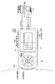
First, the waveform display mode will be described.
FIG. 4 is a configuration diagram schematically showing the display content of the
Here, for convenience of explanation, the R wave of the electrocardiographic waveform measured in time series is referred to as a first R wave, a second R wave, and a third R wave. Accordingly, the first R wave to the third R wave do not indicate a specific R wave included in the electrocardiogram waveform, but the first R wave, the second R wave, and the third R wave sequentially from the first R wave measured after the measurement is started. The wave,..., Is called the n-th R wave.
[0013]
As shown in FIG. 4, first, the peak of the first
[0014]
In this waveform display mode, the heart
Generally, the heart rate can be obtained by the following equation.
Heart rate (bpm) = 1 minute (60000 ms) ÷ RR interval (tms)
When the heart rate is found to be 180 bpm from the above formula, the next R wave circle 2 is displayed when 333.333 (ms) have elapsed from the reference point.
[0015]
Therefore, for example, when the displayable dots on the LCD of the display unit are W128 (horizontal) × H64 (vertical), if the time for tightening per dot in the horizontal axis direction is set in advance, from a fixed reference point Since the number of dots and the elapsed time are proportional to each other, the heart
Note that the RR interval t (ms) described above can also be obtained by counting the number of dots between RR.
[0016]
That is, when the heart rate is 180 bpm, 120 bpm, and 60 bpm, when the 333.333... (Ms), 666.666. Since the 2R wave circle 2 is displayed, if the heart
[0017]
When the next second R wave circle 2 is selected as a reference point by operating the
[0018]
Next, the compressed display mode will be described.
FIG. 5 is a configuration diagram schematically showing display contents of the
As shown in FIG. 5, in the portable biological data measurement device of the present invention, the electrocardiographic waveform displayed in the waveform display mode can be displayed compressed in the time axis direction.
Since the frequency characteristic of a normal R wave is about 20 Hz, when performing compression display, digital filter processing (pass band is 5 Hz to 22 Hz) that can remove the fluctuation of the base line and extract the R wave is performed.
[0019]
When the electrocardiogram waveform is normal, the RR interval is equal and an R wave is displayed at the upper part of the baseline. However, when the R wave is lost due to arrhythmia or the like, FIG. As shown in FIG. 6, since the R wave interval is displayed wide like a
Also, when abnormal waveforms such as ventricular extrasystole occur, the abnormal waveforms can be easily generated based on the waveforms different from other waveforms, as shown in the above figure and the display surrounded by the broken line of the compressed display. Can be confirmed.
[0020]
Next, the RR graph display mode will be described.
The portable biological data measurement device of the present invention has an RR graph display mode for displaying the transition of the heart rate between RRs.
In this RR graph display mode, as shown in FIG. 3C, the transition of the heart rate between RRs is displayed on a graph with the ordinate representing the heart rate and the abscissa representing the time axis.
As described above, in the RR graph display mode of the portable biological data measurement device of the present invention, since the transition of the heart rate can be visually grasped, heartbeat disturbance such as arrhythmia can be easily confirmed. .
[0021]
As described above, the portable biological data measuring device of the present invention can store the measured electrocardiogram waveform in the electrocardiogram
[0022]
【The invention's effect】
The portable biological data measuring device of the present invention is adjacent to the surface on which the GND electrode and the minus electrode are disposed on the opposite side surfaces of the substantially rectangular parallelepiped casing, and the surface on which the GND electrode and the minus electrode are provided. A positive electrode disposed on a surface curved in the shape of an elliptical arc of a cross section, and measuring biometric data using the positive electrode, the GND electrode, and the negative electrode, so that an electrocardiographic waveform can be stably measured Can do.
In addition, a display unit for displaying the biological data is provided, the first R wave and the second R wave included in the electrocardiogram waveform are displayed, and the horizontal position which is a time axis with the peak position of the first R wave as a reference point. Since the heart rate reading axis in which the heart rate is varied is displayed, it is possible to provide a portable biological data measuring device capable of instantaneously reading the heart rate.
In addition, since the display unit for displaying the biometric data is provided and the electrocardiographic waveform is compressed and displayed in the time axis direction, a portable biometric data measuring device that can easily check the occurrence of arrhythmia can be provided. .
Furthermore, a portable biometric data measuring device that includes a display unit for displaying the biometric data and displays the temporal transition of the heart rate between adjacent R waves can be easily checked for heartbeat disturbance such as arrhythmia. Can be provided.
[Brief description of the drawings]
FIG. 1 is a block diagram schematically showing a portable biological data measuring apparatus according to the present invention.
FIG. 2 is a block diagram schematically showing a system configuration of the portable biological data measuring apparatus of the present invention.
FIG. 3 is a diagram conceptually showing a flow of data processing in the portable biological data measuring apparatus of the present invention.
FIG. 4 is a configuration diagram schematically showing display contents of a display unit in a waveform display mode.
FIG. 5 is a configuration diagram schematically showing display contents of a display unit in a compressed display mode.
FIG. 6 is a block diagram schematically showing a living body risk management adapter described in Japanese Patent Laid-Open No. 9-173304.
[Explanation of symbols]
DESCRIPTION OF
16 ECG
Claims (1)
Priority Applications (3)
| Application Number | Priority Date | Filing Date | Title |
|---|---|---|---|
| JP2001351314A JP3817163B2 (en) | 2001-11-16 | 2001-11-16 | Portable biological data measuring device |
| US10/294,550 US7149571B2 (en) | 2001-11-16 | 2002-11-15 | Portable biological data measuring apparatus |
| CN02149581A CN1419888A (en) | 2001-11-16 | 2002-11-15 | Portable bio-data measuring device |
Applications Claiming Priority (1)
| Application Number | Priority Date | Filing Date | Title |
|---|---|---|---|
| JP2001351314A JP3817163B2 (en) | 2001-11-16 | 2001-11-16 | Portable biological data measuring device |
Related Child Applications (1)
| Application Number | Title | Priority Date | Filing Date |
|---|---|---|---|
| JP2006124016A Division JP4411293B2 (en) | 2006-04-27 | 2006-04-27 | Portable biological data measuring device |
Publications (2)
| Publication Number | Publication Date |
|---|---|
| JP2003144403A JP2003144403A (en) | 2003-05-20 |
| JP3817163B2 true JP3817163B2 (en) | 2006-08-30 |
Family
ID=19163641
Family Applications (1)
| Application Number | Title | Priority Date | Filing Date |
|---|---|---|---|
| JP2001351314A Expired - Fee Related JP3817163B2 (en) | 2001-11-16 | 2001-11-16 | Portable biological data measuring device |
Country Status (3)
| Country | Link |
|---|---|
| US (1) | US7149571B2 (en) |
| JP (1) | JP3817163B2 (en) |
| CN (1) | CN1419888A (en) |
Families Citing this family (70)
| Publication number | Priority date | Publication date | Assignee | Title |
|---|---|---|---|---|
| JP2005000468A (en) * | 2003-06-13 | 2005-01-06 | Omron Healthcare Co Ltd | Electrocardiograph and display method in electrocardiograph |
| JP2005046215A (en) * | 2003-07-30 | 2005-02-24 | Omron Healthcare Co Ltd | Portable type electrocardiograph |
| US8353861B2 (en) * | 2003-09-18 | 2013-01-15 | Texmac, Inc. | Applicator for applying functional substances into human skin |
| JP2005185756A (en) | 2003-12-26 | 2005-07-14 | Omron Healthcare Co Ltd | Portable electrocardiograph |
| JP4239836B2 (en) * | 2004-01-30 | 2009-03-18 | オムロンヘルスケア株式会社 | Biological information measuring device |
| JP2005211388A (en) * | 2004-01-30 | 2005-08-11 | Omron Healthcare Co Ltd | Connection unit for biological information measuring apparatus |
| JP2006061445A (en) * | 2004-08-27 | 2006-03-09 | Omron Healthcare Co Ltd | Portable type electrocardiograph |
| JP2006061494A (en) * | 2004-08-27 | 2006-03-09 | Omron Healthcare Co Ltd | Portable type electrocardiograph |
| US8060190B2 (en) * | 2004-09-13 | 2011-11-15 | Gambro Lundia Ab | Detection of drastic blood pressure changes |
| WO2007121678A1 (en) * | 2006-04-25 | 2007-11-01 | Beijing Choice Electronic Technology Co., Ltd. | Handheld electrocardiograph with neutral electrode |
| CN100376204C (en) * | 2006-04-25 | 2008-03-26 | 北京超思电子技术有限责任公司 | Handheld ECG |
| WO2008015667A2 (en) * | 2006-07-29 | 2008-02-07 | Cardicell Ltd. | Device for mobile electrocardiogram recording |
| CN101385641B (en) * | 2007-09-11 | 2015-03-25 | 深圳迈瑞生物医疗电子股份有限公司 | Wave analysis method and device of physiological parameter |
| KR101432813B1 (en) * | 2007-10-24 | 2014-08-27 | 삼성전자주식회사 | Folder-type portable electrocardiogram monitor |
| US7738320B2 (en) * | 2007-12-03 | 2010-06-15 | General Electric Co. | Method and system for enhanced display of temporal data on portable devices |
| KR20090079006A (en) * | 2008-01-16 | 2009-07-21 | 삼성전자주식회사 | Biosignal measuring apparatus, biosignal measuring sensor, pulse wave transmission rate measuring apparatus and method |
| EP2415397B1 (en) | 2009-04-02 | 2015-06-03 | Murata Manufacturing Co., Ltd. | Cardiac signal detection device |
| JP5146596B2 (en) | 2009-04-30 | 2013-02-20 | 株式会社村田製作所 | Biosensor device |
| CN102018509B (en) * | 2009-09-17 | 2013-12-18 | 周常安 | Electro-cardio signal acquiring apparatus |
| TWI474803B (en) | 2011-03-24 | 2015-03-01 | 緯創資通股份有限公司 | ECG signal sensing module, device and computer capable of assembling the same |
| WO2012165064A1 (en) | 2011-05-31 | 2012-12-06 | 株式会社村田製作所 | Pulse wave sensor device |
| US9345415B2 (en) * | 2011-12-30 | 2016-05-24 | Intel Corporation | Method and apparatus for measuring multiple ECG leads using a device with embedded leads |
| WO2013161729A1 (en) | 2012-04-25 | 2013-10-31 | 株式会社村田製作所 | Electrocardiographic signal measurement device and electrocardiographic signal measurement method |
| CN103519805B (en) * | 2012-07-06 | 2016-05-11 | 经络动力医学股份有限公司 | Handheld ECG Detection Device |
| WO2014194694A1 (en) * | 2013-06-07 | 2014-12-11 | 北京丰拓生物技术有限公司 | Electrocardiogram measurement device |
| US9619660B1 (en) | 2013-09-25 | 2017-04-11 | Bardy Diagnostics, Inc. | Computer-implemented system for secure physiological data collection and processing |
| US9717432B2 (en) | 2013-09-25 | 2017-08-01 | Bardy Diagnostics, Inc. | Extended wear electrocardiography patch using interlaced wire electrodes |
| US9700227B2 (en) | 2013-09-25 | 2017-07-11 | Bardy Diagnostics, Inc. | Ambulatory electrocardiography monitoring patch optimized for capturing low amplitude cardiac action potential propagation |
| US10433748B2 (en) | 2013-09-25 | 2019-10-08 | Bardy Diagnostics, Inc. | Extended wear electrocardiography and physiological sensor monitor |
| US11723575B2 (en) | 2013-09-25 | 2023-08-15 | Bardy Diagnostics, Inc. | Electrocardiography patch |
| US9655537B2 (en) | 2013-09-25 | 2017-05-23 | Bardy Diagnostics, Inc. | Wearable electrocardiography and physiology monitoring ensemble |
| US9737224B2 (en) | 2013-09-25 | 2017-08-22 | Bardy Diagnostics, Inc. | Event alerting through actigraphy embedded within electrocardiographic data |
| US9433367B2 (en) | 2013-09-25 | 2016-09-06 | Bardy Diagnostics, Inc. | Remote interfacing of extended wear electrocardiography and physiological sensor monitor |
| US10888239B2 (en) | 2013-09-25 | 2021-01-12 | Bardy Diagnostics, Inc. | Remote interfacing electrocardiography patch |
| US10463269B2 (en) | 2013-09-25 | 2019-11-05 | Bardy Diagnostics, Inc. | System and method for machine-learning-based atrial fibrillation detection |
| US9345414B1 (en) | 2013-09-25 | 2016-05-24 | Bardy Diagnostics, Inc. | Method for providing dynamic gain over electrocardiographic data with the aid of a digital computer |
| US10433751B2 (en) | 2013-09-25 | 2019-10-08 | Bardy Diagnostics, Inc. | System and method for facilitating a cardiac rhythm disorder diagnosis based on subcutaneous cardiac monitoring data |
| US10667711B1 (en) | 2013-09-25 | 2020-06-02 | Bardy Diagnostics, Inc. | Contact-activated extended wear electrocardiography and physiological sensor monitor recorder |
| US9408551B2 (en) | 2013-11-14 | 2016-08-09 | Bardy Diagnostics, Inc. | System and method for facilitating diagnosis of cardiac rhythm disorders with the aid of a digital computer |
| US10251576B2 (en) | 2013-09-25 | 2019-04-09 | Bardy Diagnostics, Inc. | System and method for ECG data classification for use in facilitating diagnosis of cardiac rhythm disorders with the aid of a digital computer |
| WO2015048194A1 (en) | 2013-09-25 | 2015-04-02 | Bardy Diagnostics, Inc. | Self-contained personal air flow sensing monitor |
| US10165946B2 (en) | 2013-09-25 | 2019-01-01 | Bardy Diagnostics, Inc. | Computer-implemented system and method for providing a personal mobile device-triggered medical intervention |
| US9504423B1 (en) | 2015-10-05 | 2016-11-29 | Bardy Diagnostics, Inc. | Method for addressing medical conditions through a wearable health monitor with the aid of a digital computer |
| US10736531B2 (en) | 2013-09-25 | 2020-08-11 | Bardy Diagnostics, Inc. | Subcutaneous insertable cardiac monitor optimized for long term, low amplitude electrocardiographic data collection |
| US10799137B2 (en) | 2013-09-25 | 2020-10-13 | Bardy Diagnostics, Inc. | System and method for facilitating a cardiac rhythm disorder diagnosis with the aid of a digital computer |
| US9408545B2 (en) | 2013-09-25 | 2016-08-09 | Bardy Diagnostics, Inc. | Method for efficiently encoding and compressing ECG data optimized for use in an ambulatory ECG monitor |
| US9655538B2 (en) | 2013-09-25 | 2017-05-23 | Bardy Diagnostics, Inc. | Self-authenticating electrocardiography monitoring circuit |
| US11213237B2 (en) | 2013-09-25 | 2022-01-04 | Bardy Diagnostics, Inc. | System and method for secure cloud-based physiological data processing and delivery |
| US20190167139A1 (en) | 2017-12-05 | 2019-06-06 | Gust H. Bardy | Subcutaneous P-Wave Centric Insertable Cardiac Monitor For Long Term Electrocardiographic Monitoring |
| US9730593B2 (en) | 2013-09-25 | 2017-08-15 | Bardy Diagnostics, Inc. | Extended wear ambulatory electrocardiography and physiological sensor monitor |
| US9717433B2 (en) | 2013-09-25 | 2017-08-01 | Bardy Diagnostics, Inc. | Ambulatory electrocardiography monitoring patch optimized for capturing low amplitude cardiac action potential propagation |
| US10736529B2 (en) | 2013-09-25 | 2020-08-11 | Bardy Diagnostics, Inc. | Subcutaneous insertable electrocardiography monitor |
| US9433380B1 (en) | 2013-09-25 | 2016-09-06 | Bardy Diagnostics, Inc. | Extended wear electrocardiography patch |
| US9775536B2 (en) | 2013-09-25 | 2017-10-03 | Bardy Diagnostics, Inc. | Method for constructing a stress-pliant physiological electrode assembly |
| US10624551B2 (en) | 2013-09-25 | 2020-04-21 | Bardy Diagnostics, Inc. | Insertable cardiac monitor for use in performing long term electrocardiographic monitoring |
| US9615763B2 (en) | 2013-09-25 | 2017-04-11 | Bardy Diagnostics, Inc. | Ambulatory electrocardiography monitor recorder optimized for capturing low amplitude cardiac action potential propagation |
| US9364155B2 (en) | 2013-09-25 | 2016-06-14 | Bardy Diagnostics, Inc. | Self-contained personal air flow sensing monitor |
| US10806360B2 (en) | 2013-09-25 | 2020-10-20 | Bardy Diagnostics, Inc. | Extended wear ambulatory electrocardiography and physiological sensor monitor |
| US10820801B2 (en) | 2013-09-25 | 2020-11-03 | Bardy Diagnostics, Inc. | Electrocardiography monitor configured for self-optimizing ECG data compression |
| CN103750828B (en) * | 2014-01-17 | 2016-04-13 | 深圳源动创新科技有限公司 | Handheld physiological parameter detector |
| US11229370B2 (en) * | 2014-05-05 | 2022-01-25 | Healthy.Io Ltd. | Portable device with multiple integrated sensors for vital signs scanning |
| KR101623912B1 (en) * | 2014-09-30 | 2016-05-25 | 주식회사 중앙교육 | The apparatus and method for providing contents for training noncognitive ability with the user by using a user device |
| WO2016181808A1 (en) * | 2015-05-09 | 2016-11-17 | 株式会社村田製作所 | Handheld electrocardiographic measurement device |
| KR101772279B1 (en) * | 2015-09-14 | 2017-09-05 | 주식회사 그릿연구소 | The method generating faking precision of psychological tests using bio-data of a user |
| JP6603584B2 (en) * | 2016-01-14 | 2019-11-06 | 株式会社クロスウェル | Periodic wave detection device, periodic wave detection method and program |
| WO2018066342A1 (en) * | 2016-10-07 | 2018-04-12 | 株式会社村田製作所 | Handheld pulse wave measurement device |
| US10292373B2 (en) * | 2016-10-28 | 2019-05-21 | Anthony BUGEJA | Waste-movement system for aquarium |
| US11096579B2 (en) | 2019-07-03 | 2021-08-24 | Bardy Diagnostics, Inc. | System and method for remote ECG data streaming in real-time |
| US11116451B2 (en) | 2019-07-03 | 2021-09-14 | Bardy Diagnostics, Inc. | Subcutaneous P-wave centric insertable cardiac monitor with energy harvesting capabilities |
| US11696681B2 (en) | 2019-07-03 | 2023-07-11 | Bardy Diagnostics Inc. | Configurable hardware platform for physiological monitoring of a living body |
Family Cites Families (13)
| Publication number | Priority date | Publication date | Assignee | Title |
|---|---|---|---|---|
| US4550735A (en) | 1980-12-31 | 1985-11-05 | Norio Akamatsu | Electrode for an electrocardiograph |
| JPS6099234A (en) | 1983-11-04 | 1985-06-03 | セイコーインスツルメンツ株式会社 | Portable electrocardiograph |
| JPH02206431A (en) | 1989-02-06 | 1990-08-16 | Fukuda Denshi Co Ltd | Sigma display system |
| JPH062653Y2 (en) | 1989-12-29 | 1994-01-26 | 日本光電工業株式会社 | Portable electrocardiograph |
| JPH061682Y2 (en) | 1990-06-22 | 1994-01-19 | 日本光電工業株式会社 | Portable electrocardiograph |
| US5226425A (en) | 1991-09-10 | 1993-07-13 | Ralin, Inc. | Portable ECG monitor/recorder |
| JP2691814B2 (en) | 1991-12-03 | 1997-12-17 | シャープ株式会社 | Portable electrocardiograph |
| FR2704417A1 (en) * | 1993-03-23 | 1994-11-04 | Mclaughlin James A | Device with profiled electrode (s) for the detection of bioelectric signals. |
| JPH0956686A (en) | 1995-08-28 | 1997-03-04 | Casio Comput Co Ltd | Electrocardiograph |
| US6149602A (en) | 1996-09-10 | 2000-11-21 | Arcelus; Almudena | User-worn electrocardiogram viewer device |
| JPH10314134A (en) | 1997-05-16 | 1998-12-02 | Omron Corp | Heart radio wave detection device |
| FR2773985B1 (en) | 1998-01-28 | 2000-05-05 | Sanimat Diffusion | DEVICE FOR RECORDING AN ELECTROCARDIOGRAM |
| US6370423B1 (en) * | 1998-10-05 | 2002-04-09 | Juan R. Guerrero | Method for analysis of biological voltage signals |
-
2001
- 2001-11-16 JP JP2001351314A patent/JP3817163B2/en not_active Expired - Fee Related
-
2002
- 2002-11-15 CN CN02149581A patent/CN1419888A/en active Pending
- 2002-11-15 US US10/294,550 patent/US7149571B2/en not_active Expired - Fee Related
Also Published As
| Publication number | Publication date |
|---|---|
| US7149571B2 (en) | 2006-12-12 |
| JP2003144403A (en) | 2003-05-20 |
| CN1419888A (en) | 2003-05-28 |
| US20030097078A1 (en) | 2003-05-22 |
Similar Documents
| Publication | Publication Date | Title |
|---|---|---|
| JP3817163B2 (en) | Portable biological data measuring device | |
| Specification et al. | X10 | |
| US7310550B2 (en) | Electrocardiograph and display method for electrocardiograph | |
| JP5560400B2 (en) | Electrocardiograph | |
| US20060100533A1 (en) | Apparatus and method for measuring bio signals | |
| EP2082683A1 (en) | Portable ecg measuring apparatus | |
| JPH03159636A (en) | Method and device for monitoring heart | |
| EP2592999B1 (en) | Methods and apparatus for estimating a blood volume of a mammalian subject | |
| WO2000044274A2 (en) | Personal physiological monitor | |
| JP5221926B2 (en) | Heart rate variability analysis method and analysis apparatus | |
| JP2006061494A (en) | Portable type electrocardiograph | |
| EP1985231A1 (en) | Portable electrocardiograph | |
| JPH0228887Y2 (en) | ||
| KR20160008368A (en) | Method and apparatus for processing biosignal using recursive estimation | |
| JP2003275186A (en) | Electrocardiogram monitor device | |
| JP4411293B2 (en) | Portable biological data measuring device | |
| US4624262A (en) | Apparatus and process for very rapidly measuring the heart beat rate | |
| JP3036954U (en) | Portable heartbeat interval recorder | |
| CN201563147U (en) | Mobile phone and device monitoring physiologic index of human body | |
| JP3664400B2 (en) | ECG display device | |
| JP7367480B2 (en) | Electrocardiogram measuring device | |
| JP2014116652A (en) | Sensor device, sensor system, and program | |
| CN209751033U (en) | portable electrocardiogram measuring instrument | |
| WO2007091380A1 (en) | Portable electrocardiograph | |
| JPH06339468A (en) | Physiological measuring apparatus |
Legal Events
| Date | Code | Title | Description |
|---|---|---|---|
| A621 | Written request for application examination |
Free format text: JAPANESE INTERMEDIATE CODE: A621 Effective date: 20041019 |
|
| A977 | Report on retrieval |
Free format text: JAPANESE INTERMEDIATE CODE: A971007 Effective date: 20060302 |
|
| A131 | Notification of reasons for refusal |
Free format text: JAPANESE INTERMEDIATE CODE: A131 Effective date: 20060314 |
|
| A521 | Request for written amendment filed |
Free format text: JAPANESE INTERMEDIATE CODE: A523 Effective date: 20060427 |
|
| TRDD | Decision of grant or rejection written | ||
| A01 | Written decision to grant a patent or to grant a registration (utility model) |
Free format text: JAPANESE INTERMEDIATE CODE: A01 Effective date: 20060523 |
|
| A61 | First payment of annual fees (during grant procedure) |
Free format text: JAPANESE INTERMEDIATE CODE: A61 Effective date: 20060609 |
|
| R150 | Certificate of patent or registration of utility model |
Free format text: JAPANESE INTERMEDIATE CODE: R150 |
|
| FPAY | Renewal fee payment (event date is renewal date of database) |
Free format text: PAYMENT UNTIL: 20100616 Year of fee payment: 4 |
|
| FPAY | Renewal fee payment (event date is renewal date of database) |
Free format text: PAYMENT UNTIL: 20100616 Year of fee payment: 4 |
|
| FPAY | Renewal fee payment (event date is renewal date of database) |
Free format text: PAYMENT UNTIL: 20110616 Year of fee payment: 5 |
|
| FPAY | Renewal fee payment (event date is renewal date of database) |
Free format text: PAYMENT UNTIL: 20120616 Year of fee payment: 6 |
|
| FPAY | Renewal fee payment (event date is renewal date of database) |
Free format text: PAYMENT UNTIL: 20130616 Year of fee payment: 7 |
|
| FPAY | Renewal fee payment (event date is renewal date of database) |
Free format text: PAYMENT UNTIL: 20140616 Year of fee payment: 8 |
|
| R250 | Receipt of annual fees |
Free format text: JAPANESE INTERMEDIATE CODE: R250 |
|
| LAPS | Cancellation because of no payment of annual fees |