JP3806378B2 - Spent fuel burnup measurement system - Google Patents
Spent fuel burnup measurement system Download PDFInfo
- Publication number
- JP3806378B2 JP3806378B2 JP2002238220A JP2002238220A JP3806378B2 JP 3806378 B2 JP3806378 B2 JP 3806378B2 JP 2002238220 A JP2002238220 A JP 2002238220A JP 2002238220 A JP2002238220 A JP 2002238220A JP 3806378 B2 JP3806378 B2 JP 3806378B2
- Authority
- JP
- Japan
- Prior art keywords
- spent fuel
- burnup
- detection means
- fast neutron
- fuel
- Prior art date
- Legal status (The legal status is an assumption and is not a legal conclusion. Google has not performed a legal analysis and makes no representation as to the accuracy of the status listed.)
- Expired - Lifetime
Links
Images



Classifications
-
- Y—GENERAL TAGGING OF NEW TECHNOLOGICAL DEVELOPMENTS; GENERAL TAGGING OF CROSS-SECTIONAL TECHNOLOGIES SPANNING OVER SEVERAL SECTIONS OF THE IPC; TECHNICAL SUBJECTS COVERED BY FORMER USPC CROSS-REFERENCE ART COLLECTIONS [XRACs] AND DIGESTS
- Y02—TECHNOLOGIES OR APPLICATIONS FOR MITIGATION OR ADAPTATION AGAINST CLIMATE CHANGE
- Y02E—REDUCTION OF GREENHOUSE GAS [GHG] EMISSIONS, RELATED TO ENERGY GENERATION, TRANSMISSION OR DISTRIBUTION
- Y02E30/00—Energy generation of nuclear origin
- Y02E30/30—Nuclear fission reactors
Landscapes
- Monitoring And Testing Of Nuclear Reactors (AREA)
Description
【0001】
【発明の属する技術分野】
この発明は、使用済み燃料の燃焼度測定に関し、さらに詳しくは、簡便且つ迅速に使用済み燃料の燃焼度を測定できる使用済み燃料の測定装置に関する。
【0002】
【従来の技術】
炉心内で燃焼を終え使用できなくなった核燃料を、使用済み燃料という。使用済み燃料は、核分裂生成物FPなど高放射能物質を含むので熱的に冷却する必要があるから、原子力発電所の燃料貯蔵ピットで所定期間(1〜10年間)冷却される。その後、輸送・貯蔵を目的とする収納容器であるキャスクに収納され、トラック等で再処理施設等に搬送、貯蔵される。
【0003】
キャスクや燃料貯蔵ピットに燃焼度クレジットを採用する場合には、使用済み燃料の燃焼度を測定し管理する必要がある。ここで、燃焼度クレジットとは、核燃料の燃焼による核種組成の変化を考慮した合理的な臨界安全性設計をいう。使用済み燃料の燃焼度を測定する方法としては、例えば、特開昭61−262692号公報には、γ線スペクトル分析によって使用済み燃料の燃焼度を求める方法が開示されている。
【0004】
また、特開平6−160585号公報には、使用済み燃料を計測装置に設置して、中性子検出器による中性子計数値とCd−Te検出器によるγ線スペクトル分析に基づくデータによって使用済み燃料の燃焼度を測定する方法が開示されている。さらに、特開平10−39085号公報には、γ線検出器を装着したホルダーに使用済み燃料を挟み込んで静置させて測定し、中性子計数率とγ線スペクトル分析とによって使用済み燃料の燃焼度を求める方法が開示されている。この方法には、使用済み燃料から放出されて熱化した熱中性子を測定して使用済み燃料の燃焼度を求める方法が使用されている。
【0005】
【発明が解決しようとする課題】
しかしながら、上記いずれの測定方法によっても、使用済み燃料を測定装置の架台に静置して燃焼度を測定していた。このため、使用済み燃料を測定箇所まで移動させる作業が必要であり、その作業に手間を要していた。また、上記計測方法においてはγ線スペクトル分析が利用されているので、小型の検出器を使用した場合には測定効率が小さいため信頼できるデータを取得するのに時間を要していた。
【0006】
一方、γ線スペクトル分析に大型の検出装置を使用すると検出装置が大掛かりなものとなり、大きな設置スペースを要したり製造コストが上昇したりしていた。また、熱中性子の測定は測定位置の影響が大きく、測定位置のわずかなずれによって大きく熱中性子計数値が変化してしまう。このため、熱中性子を利用する場合には測定装置の架台に静置して熱中性子を計数する必要があり、上記したものと同様の問題がある。そこで、この発明は、上記に鑑みてなされたものであって、簡便且つ迅速に使用済み燃料の燃焼度を測定できる使用済み燃料の測定装置を提供することを目的とする。
【0007】
【課題を解決するための手段】
上述の目的を達成するために、請求項1に係る使用済み燃料の燃焼度測定装置は、少なくとも高速中性子検出手段を備えた複数の放射線検出手段を使用済み燃料の側方両側に対向配置して、移動中の使用済み燃料から放出される高速中性子をそれぞれの前記放射線検出手段によって検出し、それぞれの前記放射線検出手段によって検出された高速中性子計数値の相乗平均値から前記使用済み燃料の燃焼度を求めることを特徴とする。
【0008】
ボロンを含んでいないプール水中での使用済み燃料の燃焼度測定に用いられる熱中性子を利用する方法は、上述した通り測定位置の影響を大きく受けるため、測定装置の架台に静置して測定する必要があった。このため、使用済み燃料の移動中に測定する簡易且つ迅速な測定には不向きであった。本発明者らは鋭意研究の結果、使用済み燃料の両側から高速中性子を選択的に計数して両者の計数値の相乗平均をとれば、測定位置の影響や使用済み燃料内における各燃料棒の燃焼度ばらつきを打ち消すことができることを見出した。これは、高速中性子は距離に対して指数関数的に減衰する性質を利用したものである。これによって、測定中に高速中性子検出手段等と使用済み燃料との距離が変化しても、この影響を打ち消すことができるので、使用済み燃料を燃料貯蔵ピット内で移動させる過程において、高い精度で燃焼度を求めることができるようになった。
【0009】
この使用済み燃料の燃焼度測定装置は、少なくとも高速中性子検出手段を備えた複数の放射線検出手段を対向配置して、この間を使用済み燃料が通過する間、又は停止中に高速中性子計数値を測定する。そして、対向配置したそれぞれの放射線検出手段で検出された高速中性子計数値と燃焼度及び冷却期間との関係から、使用済み燃料の燃焼度を求める。このため、使用済み燃料を燃料貯蔵ピットからキャスクピットへ移動させる間に使用済み燃料の燃焼度を求めることができる。その結果、使用済み燃料の燃焼度を測定するために測定装置まで使用済み燃料を移動させたり、測定装置へ使用済み燃料を取り付けたりする特別な燃料ハンドリングが不要になるので、測定作業の安全性を高くできる。また、使用済み燃料の移動中に燃焼度の測定が完了するので、測定に要する時間を従来よりも短くでき、これによって検出器の放射線損傷も低減できる。
【0010】
一方、放射線検出手段の間に使用済み燃料を停止させて高速中性子等を検出して燃焼度を求めることもできる。この場合には、使用済み燃料の移動中に燃焼度を求める場合と比較して測定時間を長くすることにより、高速中性子等の積算計数を多くできる。これによって計数の統計誤差を低減できるので、燃焼度の測定精度をさらに向上させることができる。
【0011】
さらに、この使用済み燃料の燃焼度測定装置では、高速中性子を選択的に計数して、計数値の相乗平均値によって燃焼度を求める。これによって、使用済み燃料の移動時における放射線検出器方向へのずれ、及び使用済み燃料の横方向(長手方向に対して垂直な方向)における燃焼度分布を打ち消して、使用済み燃料全体を平均した燃焼度に対応する中性子計数値を精度よく求めることができる。なお、高速中性子とは、エネルギーが約0.5eV以上の中性子をいう(以下同様)。また、エネルギーが約0.5eVよりも小さい中性子は熱中性子という(以下同様)。また、本発明にいう使用済み燃料には、複数の核燃料棒を筐体内に備えた、いわゆる使用済み燃料集合体も含まれるものとする(以下同様)。
【0012】
また、請求項2に係る使用済み燃料の燃焼度測定装置は、使用済み燃料の側方両側に対向配置される、少なくとも高速中性子検出手段を備えた複数の放射線検出手段と、対向配置される前記放射線検出手段によって、移動中の使用済み燃料から検出された高速中性子計数値の相乗平均値を算出し、これと使用済み燃料の燃焼率との関係を用いて使用済み燃料の燃焼度を求めるデータ処理手段と、前記使用済み燃料の燃焼度が所定の値を下回る場合には、その使用済み燃料の移動を中止する信号、警報機を作動させる信号その他の警報信号を発生させる信号発生手段と、を備えたことを特徴とする。
【0013】
この使用済み燃料の燃焼度測定装置は、データ処理手段によって高速中性子計数値から使用済み燃料の燃焼度を求めるので、迅速に使用済み燃料の燃焼度を求めることができる。また、使用済み燃料の冷却期間に応じて定まる所定の値よりも燃焼度が小さい場合には、信号発生手段からの警報信号により警報機を作動させたり使用済み燃料の移動を中止したりできる。その結果、燃焼度クレジットを採用したキャスク又はプールへの装荷作業において、高い反応度を有する燃焼度の低い使用済み燃料をキャスク等に収納するおそれがなくなるので安全性を高くできる。
【0014】
また、請求項3に係る使用済み燃料の燃焼度測定装置は、請求項1又は2に記載の使用済み燃料の燃焼度測定装置において、さらに、上記放射線検出手段にはγ線検出手段が備えられ、上記放射線検出手段によって検出された高速中性子計数値の相乗平均値とグロスγ線量率の相乗平均値とによって使用済み燃料の燃焼度を求めることを特徴とする。
【0015】
この使用済み燃料の燃焼度測定装置は、さらにγ線検出手段を備え、高速中性子計数値の相乗平均値とグロスγ線量率の相乗平均値とによって使用済み燃料の燃焼度を求める。このため、炉心管理データが利用できない場合であっても、グロスγ線量率によって使用済み燃料の冷却期間の効果を補正して燃焼度を求めることができるので、汎用性を高くできる。また、炉心管理データを使用できる場合であっても、グロスγ線量率によって燃焼度を検定できるので、炉心管理データと測定値との整合性を確認でき、システムの信頼性を向上させることができる。
【0016】
また、請求項4に係る使用済み燃料の燃焼度測定装置は、請求項1〜3のいずれか1項に記載の使用済み燃料の燃焼度測定装置において、上記放射線検出手段は、使用済み燃料の長手方向における一定の高さに配置されることを特徴とする。使用済み燃料は一般に細長い構造であり、長手方向に高速中性子等の放射分布を持つ。そこで、このように、使用済み燃料の長手方向における一定の高さに放射線検出手段を配置すれば、使用済み燃料の長手方向における高速中性子等の放射分布の影響を低減できるので、精度の高い測定ができる。
【0017】
また、請求項5に係る使用済み燃料の燃焼度測定装置は、請求項1〜4のいずれか1項に記載の使用済み燃料の燃焼度測定装置において、上記放射線検出手段は、使用済み燃料の移動経路の途中に備えられていることを特徴とする。このような構成により、使用済み燃料を燃料貯蔵ピットからキャスクピットへ移動する間に燃焼度を測定できるので、従来のように測定装置に使用済み燃料を設置する等の手間を要さない。移動中の使用済み燃料を測定することによって、測定作業に要する時間を大幅に短縮できるので作業効率を向上させることができる。また、測定時間の短縮によって測定装置の放射線損傷を低減できるので、測定装置の信頼性が向上する。
【0018】
また、請求項6に係る使用済み燃料の燃焼度測定装置は、請求項1〜5のいずれか1項に記載の使用済み燃料の燃焼度測定装置において、上記高速中性子検出手段は、さらに中性子吸収材を有する熱中性子吸収層を備えたことを特徴とする。
【0019】
この使用済み燃料の燃焼度測定装置は、ボロンを含有しない水、すなわち中性子吸収材を含まない水が満たされた燃料貯蔵ピット等における使用に際して、高速中性子検出手段にカドミウム、ハフニウム等の熱中性子吸収層を設けたので、熱中性子吸収層で熱中性子を吸収して高速中性子を選択的に検出できる。これによって、一般にボロン非含有水中に貯蔵されるBWR(Boiling Water Reactor:沸騰水型原子炉)用の使用済み燃料の燃焼度測定装置としても使用できるので、測定時間を短縮したり安全性を向上させたりすることができる。
【0020】
【発明の実施の形態】
以下、この発明につき図面を参照しつつ詳細に説明する。なお、この実施の形態によりこの発明が限定されるものではない。また、下記実施の形態における構成要素には、当業者が容易に想定できるもの或いは実質的に同一のものが含まれるものとする。なお、この発明に係る使用済み燃料の燃焼度測定装置及び測定方法は、特にPWR(Pressurized Water Reactor:加圧水型原子炉)用の使用済み燃料に適するが、BWR用の使用済み燃料にも適用できる。
【0021】
(実施の形態1)
図1は、この発明の実施の形態1に係る使用済み燃料の燃焼度測定装置を配置した使用済み燃料プールを示す説明図である。また、図2は、この発明の実施の形態1に係る使用済み燃料の燃焼度測定装置の検出部を示す説明図である。この使用済み燃料の燃焼度測定装置10は、少なくとも高速中性子検出手段22を備えた複数の放射線検出手段20を対向配置し、この間に使用済み燃料30を通過させて使用済み燃料30の側面から放射される高速中性子等を測定して使用済み燃料30の燃焼度Bを求める点に特徴がある。
【0022】
炉心内で燃焼を終え使用できなくなった使用済み燃料30は、水で満たされた使用済み燃料貯蔵ピット32に備えられる貯蔵ラック36に挿入されて所定の期間冷却される。使用済み燃料貯蔵ピット32内の貯蔵ラック36で所定の期間冷却された使用済み燃料30は、輸送・貯蔵を目的とする収納容器であるキャスク40内に収納されて、トラック等により再処理施設等に搬送、貯蔵される。
【0023】
キャスク40内に収納される使用済み燃料30は、燃料ハンドリングクレーン44のワイヤ44wに取り付けられた燃料支持棒44'によって貯蔵ラック36内から一体ずつ取り出された後、移動経路であるキャナル部38を通過してキャスクピット34へ搬送される。そして、キャスクピット34内に設置されたキャスク40内に収納される。キャスク40内には、格子状セルが複数形成されたバスケット42が配置されており、使用済み燃料30は格子状のセルにそれぞれ1体ずつ挿入される。
【0024】
使用済み燃料30の燃焼度を使用済み燃料30の移動中に測定するため、高速中性子等の放射線検出手段20は、使用済み燃料30の移動経路途中に設ける必要がある。また、この発明においては、図2に示すように、二台の放射線検出手段20を使用済み燃料30の両側面に配置して、高速中性子を計数する。このため、幅の狭いキャナル部38の両側面381、382に、それぞれ本発明に係る使用済み燃料の燃焼度測定装置10の放射線検出手段20が取り付けられている。そして、使用済み燃料30が使用済み燃料貯蔵ピット32からキャスクピット34へ移動する間に、この高速中性子検出手段22によって、使用済み燃料30から放出される高速中性子が計数される。
【0025】
なお、使用済み燃料貯蔵ピット32やキャスクピット34の構造によっては、使用済み燃料30の移動経路途中にキャナル部38のような幅の狭い部分が存在しない場合もある。このような場合には、図1(c)に示すように、使用済み燃料貯蔵ピット32とキャスクピット34との間にゲート部31を設けて、ここに放射線検出手段20を設ける。
【0026】
次に、図2を用いてこの発明に係る使用済み燃料の燃焼度測定装置10について説明する。放射線検出手段20は、γ線量率計24と中性子検出部22sを有する高速中性子検出手段22とによって構成されている。なお、後述するデータ処理の際に炉心管理データを利用できる場合には、必ずしもγ線量率計24を使用する必要はない。
【0027】
図2(b)に示すように、キャナル部38に対向して配置される二台の放射線検出手段20は架台26に取り付けられる。そして、使用済み燃料30の長手方向における一定の高さhに位置するように配置される。なお、放射線検出手段20は使用済み燃料30の長手方向略中央部に配置することが好ましいが、使用済み燃料30の長手方向における高速中性子等の放射分布が一定の部分であれば、必ずしも中央部付近に配置しなくともよい。
【0028】
また、測定のばらつきを低減するため、架台頂部26aから二台の放射線検出手段20までの深さDは同じ大きさになるようにしてある。これによって、使用済み燃料30の長手方向における一定の高さhの位置に二台の放射線検出手段20が対向配置されて、測定のバラツキを低減できる。そして、対向配置される二台の放射線検出手段20の間を使用済み燃料30が通過する間に、使用済み燃料30の両側から高速中性子とγ線とを測定する。
【0029】
この使用済み燃料の燃焼度測定装置10では、使用済み燃料30が放射線検出手段20を通過する間に測定を終了する必要がある。このため、放射線検出手段20を構成するγ線量率計24には、短時間で測定のできるグロスγ線量率計を使用して、ピークの線量率を計測する。グロスγ線量率計には、例えば光伝送型のγ線検出器や電離箱型検出器を使用することができる。
【0030】
図3は、この発明の実施の形態1に係る高速中性子検出手段を示す断面図である。高速中性子検出手段22の中性子検出部22sには、ボロン被覆検出器、光伝送型シンチレーション中性子検出器、あるいは核分裂計数管等が使用できる。特に光伝送型シンチレーション中性子検出器やボロン被覆検出器は、許認可が不要であるため好ましい。また、高速中性子検出手段22は、図3(a)に示すように、厚さu1が数cmの鉛22Pbと厚さu2が数cmのポリエチレン22pとで被覆してある。鉛22Pbで被覆するのは、中性子を検出するために使用済み燃料30から放射されるγ線の線量率を低くして、中性子nとγ線との弁別性を向上させることにより、高速中性子の測定精度を高くするためである。また、ポリエチレン22pで被覆するのは、高速中性子検出手段22に到達する高速中性子を減速させて、高速中性子検出手段22の検出感度を向上させるためである。
【0031】
この発明に係る使用済み燃料の燃焼度測定装置10は、特にPWR用の使用済み燃料30の燃焼度を測定する場合に適する。PWR用の使用済み燃料貯蔵ピット32は、中性子吸収能が大きいボロンを2000ppm程度添加した水で満たされている。したがって、使用済み燃料30から放射される熱中性子はほとんど水中のボロンに吸収されてしまい、高速中性子検出手段22の中性子検出部22sに到達するのはほとんどが高速中性子である。このため、高速中性子を検出するためにポリエチレン22pで高速中性子検出手段22を被覆するのである。
【0032】
一方、BWR用の使用済み燃料は、ボロンを含有しない水で満たされた使用済み燃料貯蔵ピットに貯蔵される。このような環境下でこの発明に係る使用済み燃料の燃焼度測定装置10を使用すると、高速中性子の他、熱中性子も高速中性子検出手段22に到達する結果、高速中性子の検出精度を低下させてしまう。このような場合には、図3(b)に示す高速中性子検出手段22'のように、ポリエチレン22pの外側にカドミウム(Cd)やハフニウム(Hf)、ボロン(B)、ガドリニウム(Gd)その他の中性子吸収断面積の大きい中性子吸収材で構成した熱中性子吸収層22Cdを設ける。そして、この中性子吸収層22dによって熱中性子を遮断し、ポリエチレン22pで減速された高速中性子成分のみが高速中性子検出手段22に到達するようにして、使用済み燃料から放出される高速中性子を検出する。
【0033】
図4は、この発明の実施の形態1に係る使用済み燃料の燃焼度測定装置のデータ処理系統例を示す説明図である。使用済み燃料30は、燃料ハンドリングクレーン44によって貯蔵ラック36内から一体ずつ取り出された後、高さを一定に保ってキャナル部38を通過する。ここで、測定の都合上、燃料ハンドリングクレーン44の移動速度は3.0〜4.0m/分以下程度が好ましい。そして、放射線検出手段20の長さにもよるが、放射線検出手段20を通過する時間は1分以下程度となる。使用済み燃料30がキャナル部38を通過する間に、使用済み燃料30から放射される高速中性子とγ線とがキャナル部38に備えられた放射線検出手段201、202で検出される。検出データはデータ処理手段50に設けられた信号処理回路52へ送られて、演算部54が処理しやすい形に加工する。なお、図4(b)に示すように、データ処理手段50は、信号処理回路52とコンピュータ56とによって構成してもよい。
【0034】
このとき、放射線検出手段201、202の入口と出口とに使用済み燃料30の位置検出センサ60i、60oを設けて、これらのセンサから送られる使用済み燃料30の位置情報によって、データの取り込みを開始・終了する。また、放射線検出手段201等によって検出される高速中性子等が所定の値を超えたら、これをトリガー信号としてデータの取り込みを開始し、高速中性子等が所定の値以下になったらデータの取り込みを終了するようにしてもよい。さらに、燃料ハンドリングクレーン44の位置情報を基準としてデータの取り込みを開始・終了してもよい。
【0035】
また、使用済み燃料30を対向して設けられる放射線検出手段201、202の間で所定の時間だけ静止させて、使用済み燃料30から放射される高速中性子とγ線とを測定してもよい。この場合には、例えば使用済み燃料30の位置検出センサ60i、60oや燃料ハンドリングクレーン44の位置情報によって、対向して設けられる放射線検出手段201、202の間に使用済み燃料30が移動したことを検知してから測定を開始し、所定の時間だけ測定を継続する。所定の時間はタイマーやカウンタ等の計数手段によって求める。このようにすると、測定のために使用済み燃料30が停止している分だけ測定時間を長くできるので、高速中性子等の積算計数を多くできる。これによって、計数の統計誤差を低減できるので、燃焼度の測定精度をさらに向上させることができる。
【0036】
ここで、上記演算部54は専用のハードウエアにより実現されるものであってもよく、また、この演算部54はメモリおよびCPU(中央演算装置)により構成され、演算部54の機能を実現するためのプログラム(図示省略)をメモリにロードして実行することによりその機能を実現させるものであってもよい。また、このデータ処理手段50には、周辺機器として入力装置、表示装置など(いずれも図示省略)をメモリにロードして実行することによりその機能を実現させるものであってもよい。また、演算部54の代わりにコンピュータ56を使用する場合には、周辺機器として入力装置、表示装置など(いずれも図示省略)が接続されるものとする。ここで、入力装置とはキーボード、マウス等の入力デバイスのことをいう。表示装置とはCRT(Cathode Ray Tube)や液晶表示装置などのことをいう。
【0037】
信号処理回路52から送られてきた検出データを受け取った演算部54は、次に説明するデータ処理手順によって測定対象の使用済み燃料30の燃焼度を算出する。まず、高速中性子検出手段221及び222で検出された中性子係数値をそれぞれS1及びS2とし、γ線量率計241及び242で検出されたグロスγ線量率をG1及びG2とする。そして、この発明においては、これらの値の相乗平均√(S1×S2)及び√(G1×G2)、を求めて使用済み燃料30の中性子係数値S及びグロスγ線量率Gとする。この理由を次に説明する。
【0038】
使用済み燃料30は長さが3〜4mあり、長手方向の長さが大きい。この発明においては、従来の使用済み燃料の燃焼度測定装置とは異なり、使用済み燃料30から放射される中性子のうち高速中性子を選択的に測定する。このため、使用済み燃料30の近傍に高速中性子検出手段221、222を設置すると、使用済み燃料30と高速中性子検出手段22との距離変化に対し中性子係数値Sは指数関数的に変化する。また、γ線量率Gも同様に、指数関数的に変化する。したがって、高速中性子検出手段221及び222で検出される高速中性子の計数値は、それぞれ
【数1】

【0039】
いま、使用済み燃料30が高速中性子検出手段221に向かってΔlだけ近づいた場合を考える。このとき、高速中性子検出手段221及び222で検出される高速中性子の計数値は、それぞれ
【数2】
【数3】
【0040】
また、使用済み燃料30の内部に備えられた燃料棒の燃焼度にばらつきがある場合でも、分布に各高速中性子検出手段221及び222で検出された高速中性子係数値S1とS2との相乗平均をとってこれを高速中性子計数値Sとすれば、このばらつきを排除できる。使用済み燃料30の大きさは一定であり、使用済み燃料30内部においても高速中性子は略指数関数的に減衰する。したがって、使用済み燃料30の中心からΔr離れた燃料棒35の燃焼度が偏っていても、中性子係数値S1とS2とを相乗平均することによって、Δrの影響を打ち消すことができるからである。これによって、すべての燃料棒35が使用済み燃料30の断面内中心部に存在する場合と同様に評価できるので、各燃料棒の燃焼度ばらつきの影響を考慮する必要がなくなる。これは、グロスγ線量率Gについても同様である。
【0041】
中性子計数値S及びグロスγ線量率Gを求めたら、これらの値から使用済み燃料30の燃焼度Bを求める。PWRの使用済み燃料では、高速中性子計数値Sとグロスγ線量率Gとは次の式で表すことができる。
【数4】
G=K3×t-c×Bd・・・(2)
ここで、cはα+β×logt(α、βは定数)で表される定数であり、また、dは1程度の定数である。
【0042】
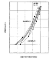
上記関係式から、使用済み燃料30の燃焼度Bを求める。まず、測定した高速中性子計数値Sとグロスγ線量率Gとを、上記式(1)と式(2)とに代入して、両式を連立させて使用済み燃料30の燃焼度Bを求める。このとき、初期濃縮度Eは、通常使用される取替燃料の初期濃縮度Eの値(例えば4.1%)を代入する。これは、PWRにおいては取替燃料の初期濃縮度Eは、特殊な場合を除いて一定だからである。また、上記式(1)と式(2)とを用いて、図5に示すようなグロスγ線量率Gをパラメータとした高速中性子計数値Sと燃焼度Bとの関係を予め求めておいて、測定した高速中性子計数値S及びグロスγ線量率Gから燃焼度Bを読み取ってもよい。なお、図5は、グロスγ線量率をパラメータとしたときにおける高速中性子計数値と燃焼度との関係を示す説明図である。
【0043】
上記手順は、炉心管理データが利用できない場合に燃焼度Bを求める手順であるが、炉心管理データが利用できる場合にはこれを利用して燃焼度Bを求めてもよい。この場合には、炉心管理データの初期濃縮度Eと冷却期間t、及び測定した高速中性子計数値Sを式(1)に代入して、燃焼度Bを求めることができる。燃焼度Bと高速中性子計数値Sとの関係は図6に示すような傾向にあるので、高速中性子計数値Sから燃焼度Bを求める際の誤差は小さくなる。ここで、図6は、高速中性子計数値と燃焼度との関係を示す説明図である。
【0044】
このように、炉心管理データの初期濃縮度Eと冷却期間tとが利用できる場合には、高速中性子計数値Sのみから燃焼度Bを求めることができるが、測定したグロスγ線量率Gは、高速中性子の測定が所定のγ線量率Gの範囲内で行われているかどうかの確認に使用できる。また、グロスγ線量率G及び冷却期間tを式(2)に代入して、使用済み燃料の燃焼度測定装置10の動作確認に利用できる。すなわち、式(2)から求めた燃焼度B2と式(1)から求めた燃焼度B1とに大きな違いがあれば、使用済み燃料の燃焼度測定装置10に何らかの異常が発生したと推定できる。
【0045】
上記手順によって求めた使用済み燃料30の燃焼度Bが、冷却期間tに応じて定まる所定の値よりも小さい場合には、警報信号を発生する信号発生手段58から警報信号を発生させることができる。そして、この警報信号によって、例えば警報ランプ51を点燈させたり、警報音を発生させたり、あるいは燃料ハンドリングクレーン44の停止させたりすることができる。また、燃料ハンドリングクレーン44を逆に動かして、使用済み燃料貯蔵ピット32の貯蔵ラック36へ使用済み燃料30を戻すこともできる。なお、信号発生手段58としてコンピュータ56内の信号発生回路(図示せず)を利用してもよい。燃焼度Bが冷却期間tに応じた所定の値よりも大きい場合には、キャスクピット34内に設置されるキャスク40内に使用済み燃料30を収納する。
【0046】
このように、本発明に係る使用済み燃料30の燃焼度測定装置10においては、対向配置された放射線検出手段20の高速中性子検出手段22によって使用済み燃料30の両側面から放射される高速中性子を計数し、二つの計数値を相乗平均する。したがって、使用済み燃料30の移動時における放射線検出手段20方向に対するずれ、及び使用済み燃料30内における横方向(使用済み燃料30の長手方向に対して垂直な方向)の燃焼度分布を打ち消すことができる。これによって、使用済み燃料30の平均燃焼度に対応する高速中性子計数値S及びグロスγ線量率Gを精度よく求めることができる。また、従来は放射線検出手段20方向に対するずれ等を補正する必要があったが、この使用済み燃料の燃焼度測定装置10においては、このような補正のための装置や演算が不要になるため、装置の構成やデータ処理を簡略化できる。
【0047】
さらに、この発明に係る使用済み燃料の燃焼度測定装置10では、使用済み燃料30の移動中に燃焼度Bを測定できる。これによって、燃焼度Bを測定するために測定装置まで使用済み燃料30を移動させたり測定装置へ使用済み燃料30を取り付けたりする特別な燃料ハンドリングが不要になるので、測定作業の安全性を高くできる。また、既設及び新設の使用済み燃料貯蔵ピット32やキャスクピット34等に設けられた通例の使用済み燃料搬出路、つまりすべての使用済み燃料30が通過する経路にこの発明に係る使用済み燃料の燃焼度測定装置10を設ける。これによって、使用済み燃料30の燃焼度Bを測定するために使用済み燃料30を迂回させずに燃焼度Bを測定できるため、測定の手間を大幅に低減できる。さらに、使用済み燃料30の移動中に燃焼度Bの測定が完了するので、測定に要する時間を従来よりも短くできる。その結果、測定時間が短くなるので、放射線検出手段20等の放射線損傷を低減できる。
【0048】
【発明の効果】
以上説明したように、この発明に係る使用済み燃料の燃焼度測定装置(請求項1)では、複数の放射線検出手段を対向配置して、この間に使用済み燃料を通過又は停止させて高速中性子計数値を測定し、それぞれの放射線検出手段で検出された高速中性子計数値の相乗平均値に基づいて使用済み燃料の燃焼度を求めるようにした。このため、燃焼度測定のための特別な燃料ハンドリングが不要になるので、測定作業の安全性を高くできる。また、使用済み燃料の移動中に燃焼度の測定が完了するので、測定に要する時間を従来よりも短くでき、これによって測定装置の放射線損傷も低減できる。さらに、選択的に計数した高速中性子計数値の相乗平均値によって燃焼度を求めるので、使用済み燃料の移動時における水平方向のずれ等を打ち消して、燃焼度を精度よく求めることができる。また、放射線検出手段の間に使用済み燃料を停止させて高速中性子等を検出して燃焼度を求めるようにすれば、高速中性子等の積算計数を多くすることができる。これによって計数の統計誤差を低減できるので、燃焼度の測定精度をさらに向上させることができる。
【0049】
また、この発明に係る使用済み燃料の燃焼度測定装置(請求項2)では、データ処理手段によって高速中性子計数値から使用済み燃料の燃焼度を求めるようにしたので、迅速に使用済み燃料の燃焼度を求めることができる。また、使用済み燃料の冷却期間に応じて定まる所定の値よりも燃焼度が小さい場合には、信号発生手段からの警報信号により警報機を作動させたり使用済み燃料の移動を中止させたりすることができる。これによって、高い反応度を有する燃焼度の低い使用済み燃料をキャスク内に収納するおそれがなくなる。
【0050】
また、この発明に係る使用済み燃料の燃焼度測定装置(請求項3)では、さらにγ線検出手段を備え、高速中性子計数値の相乗平均値とグロスγ線量率の相乗平均値とによって使用済み燃料の燃焼度を求めるようにした。このため、炉心管理データが存在しない場合であっても、グロスγ線量率によって使用済み燃料の燃焼度を求めることができるので、汎用性を高くできる。
【0051】
また、この発明に係る使用済み燃料の燃焼度測定装置(請求項4)では、使用済み燃料の長手方向一定の高さに放射線検出手段を配置したので、使用済み燃料の長手方向における高速中性子等の放射分布の影響を低減できるので、精度の高い測定ができる。
【0052】
また、この発明に係る使用済み燃料の燃焼度測定装置(請求項5)では、放射線検出手段を使用済み燃料の移動経路の途中に配置した。このため、使用済み燃料を燃料貯蔵ピットからキャスクピットへ移動する間に燃焼度を測定できるので、測定時間を大幅に短縮できる。また、測定時間が短くなる結果、放射線損傷を低減できるので安全性が向上する。
【0053】
また、この発明に係る使用済み燃料の燃焼度測定装置(請求項6)では、高速中性子検出手段にカドミウム等の熱中性子吸収層を設けたので、高速中性子を選択的に検出できる。これによって、ボロンを含有しない水中に貯蔵されるBWR用の使用済み燃料の燃焼度を測定する場合でも、この発明に係る使用済み燃料の燃焼度測定装置を適用して、迅速に測定できる。
【図面の簡単な説明】
【図1】この発明の実施の形態1に係る使用済み燃料の燃焼度測定装置を配置した使用済み燃料プールを示す説明図である。
【図2】この発明の実施の形態1に係る使用済み燃料の燃焼度測定装置の検出部を示す説明図である。
【図3】この発明の実施の形態1に係る高速中性子検出手段を示す断面図である。
【図4】この発明の実施の形態1に係る使用済み燃料の燃焼度測定装置のデータ処理系統例を示す説明図である。
【図5】グロスγ線量率をパラメータとしたときにおける高速中性子計数値と燃焼度との関係を示す説明図である。
【図6】高速中性子計数値と燃焼度との関係を示す説明図である。
【符号の説明】
10、11、12 使用済み燃料の燃焼度測定装置
20、201、202 放射線検出手段
22、22'、221、222 高速中性子検出手段
22s 中性子検出部
24、241、242 γ線量率計
26、28 架台
26b 距離固定手段
30 使用済み燃料
31 ゲート部
38 キャナル部
44 燃料ハンドリングクレーン
44' 燃料支持棒
50 データ処理手段
51 警報ランプ
52 信号処理回路
54 演算部
56 コンピュータ
58 信号発生手段[0001]
BACKGROUND OF THE INVENTION
The present invention relates to measurement of burnup of spent fuel, and more particularly to a spent fuel measurement apparatus that can measure burnup of spent fuel simply and quickly.
[0002]
[Prior art]
Nuclear fuel that has become unusable after burning in the core is called spent fuel. Since the spent fuel contains a highly radioactive substance such as the fission product FP, it needs to be thermally cooled, so it is cooled in a fuel storage pit of a nuclear power plant for a predetermined period (1 to 10 years). After that, it is stored in a cask that is a storage container for transportation and storage, and is transported and stored in a reprocessing facility or the like by a truck or the like.
[0003]
When burnup credits are used for casks and fuel storage pits, burnup of spent fuel must be measured and managed. Here, the burn-up credit refers to a rational critical safety design that takes into account changes in the nuclide composition due to combustion of nuclear fuel. As a method for measuring the burnup of the spent fuel, for example, JP-A-61-262692 discloses a method for determining the burnup of the spent fuel by γ-ray spectrum analysis.
[0004]
In Japanese Patent Laid-Open No. 6-160585, spent fuel is installed in a measuring device, and combustion of spent fuel is performed based on data based on a neutron count value by a neutron detector and γ-ray spectrum analysis by a Cd-Te detector. A method for measuring degrees is disclosed. Further, Japanese Patent Laid-Open No. 10-39085 discloses that the spent fuel is measured by sandwiching the spent fuel in a holder equipped with a γ-ray detector, and measuring the neutron count rate and γ-ray spectrum analysis. Is disclosed. In this method, a method is used in which the burnup of the spent fuel is determined by measuring thermal neutrons released from the spent fuel and heat.
[0005]
[Problems to be solved by the invention]
However, in any of the above-described measurement methods, the burnup is measured by placing the spent fuel on the frame of the measurement device. For this reason, the operation | work which moves a spent fuel to a measurement location is required, and the operation | work required the effort. In the above measurement method, since γ-ray spectrum analysis is used, when a small detector is used, it takes time to obtain reliable data because measurement efficiency is low.
[0006]
On the other hand, when a large-sized detection device is used for γ-ray spectrum analysis, the detection device becomes large, which requires a large installation space and increases manufacturing costs. Moreover, the measurement of thermal neutrons is greatly affected by the measurement position, and the thermal neutron count value changes greatly due to a slight shift in the measurement position. For this reason, when using thermal neutrons, it is necessary to count the thermal neutrons by placing them on the gantry of the measuring apparatus, and there are problems similar to those described above. Therefore, the present invention has been made in view of the above, and an object of the present invention is to provide a spent fuel measuring device capable of measuring the burnup of spent fuel simply and quickly.
[0007]
[Means for Solving the Problems]
In order to achieve the above-mentioned object, a burnup measuring apparatus for spent fuel according to claim 1 comprises a plurality of radiation detection means having at least fast neutron detection means arranged opposite to both sides of the spent fuel. , Move In Fast neutrons emitted from the spent fuel are detected by the respective radiation detection means, and the burnup of the spent fuel is determined from the geometric mean value of the fast neutron count values detected by the respective radiation detection means. Features.
[0008]
The method using thermal neutrons used to measure the burnup of spent fuel in pool water that does not contain boron is greatly affected by the measurement position as described above. There was a need. For this reason, it is not suitable for simple and quick measurement that is performed while the spent fuel is moving. As a result of diligent research, the present inventors have selectively counted fast neutrons from both sides of the spent fuel, and obtained a geometric average of both count values. It was found that the burn-up variation can be canceled out. This utilizes the property that fast neutrons decay exponentially with distance. As a result, even if the distance between the fast neutron detection means and the spent fuel changes during the measurement, this effect can be counteracted, so that the spent fuel is moved with high accuracy in the process of moving in the fuel storage pit. The burnup can now be determined.
[0009]
This spent fuel burn-up measuring device has a plurality of radiation detection means provided with at least fast neutron detection means facing each other, and measures the fast neutron count value while the spent fuel passes between them or during stoppage. To do. Then, the burnup degree of the spent fuel is obtained from the relationship between the fast neutron count value detected by each of the radiation detectors arranged oppositely, the burnup degree, and the cooling period. For this reason, the burnup of the spent fuel can be obtained while the spent fuel is moved from the fuel storage pit to the cask pit. As a result, there is no need for special fuel handling to move the spent fuel to the measuring device or to attach the spent fuel to the measuring device in order to measure the burnup of the spent fuel. Can be high. Moreover, since the measurement of the burnup is completed during the movement of the spent fuel, the time required for the measurement can be made shorter than before, thereby reducing the radiation damage of the detector.
[0010]
On the other hand, the burnup can also be obtained by stopping the spent fuel between the radiation detection means and detecting fast neutrons and the like. In this case, the accumulated count of fast neutrons and the like can be increased by lengthening the measurement time as compared with the case where the burnup is obtained during the movement of spent fuel. As a result, the statistical error in counting can be reduced, and the measurement accuracy of the burnup can be further improved.
[0011]
Further, in this spent fuel burnup measuring apparatus, fast neutrons are selectively counted, and the burnup is obtained by the geometric mean value of the counted values. As a result, the displacement of the spent fuel in the direction of the radiation detector and the burnup distribution in the lateral direction (perpendicular to the longitudinal direction) of the spent fuel were canceled out, and the entire spent fuel was averaged. The neutron count value corresponding to the burnup can be obtained with high accuracy. Fast neutrons refer to neutrons having an energy of about 0.5 eV or more (the same applies hereinafter). A neutron whose energy is smaller than about 0.5 eV is called a thermal neutron (the same applies hereinafter). In addition, the spent fuel referred to in the present invention includes a so-called spent fuel assembly including a plurality of nuclear fuel rods in a casing (the same applies hereinafter).
[0012]
A spent fuel burnup measuring device according to
[0013]
Since this spent fuel burn-up measuring apparatus obtains the burn-up degree of the spent fuel from the fast neutron count value by the data processing means, the burn-up degree of the spent fuel can be quickly found. Further, when the burnup is smaller than a predetermined value determined in accordance with the cooling period of the spent fuel, an alarm device can be activated or the movement of the spent fuel can be stopped by an alarm signal from the signal generating means. As a result, in the loading operation to the cask or the pool that employs the burn-up credit, there is no possibility that spent fuel having a high reactivity and low burn-up is stored in the cask or the like, so that safety can be increased.
[0014]
The spent fuel burnup measuring apparatus according to claim 3 is the spent fuel burnup measuring apparatus according to
[0015]
This spent fuel burn-up measuring device further includes γ-ray detection means, and determines the burn-up degree of spent fuel from the geometric mean value of the fast neutron count value and the geometric mean value of the gross γ dose rate. For this reason, even when the core management data is not available, the burnup can be obtained by correcting the effect of the spent fuel cooling period by the gross γ dose rate, and therefore, versatility can be enhanced. Even if core management data can be used, the burnup can be verified by the gross γ dose rate, so the consistency between the core management data and measured values can be confirmed, and the reliability of the system can be improved. .
[0016]
A spent fuel burnup measuring device according to claim 4 is the spent fuel burnup measuring device according to any one of claims 1 to 3, wherein the radiation detecting means It is arranged at a certain height in the longitudinal direction. Spent fuel generally has an elongated structure, and has a radiation distribution such as fast neutrons in the longitudinal direction. Therefore, if the radiation detection means is arranged at a certain height in the longitudinal direction of the spent fuel in this way, the influence of the radiation distribution of fast neutrons, etc. in the longitudinal direction of the spent fuel can be reduced. Can do.
[0017]
A spent fuel burnup measuring device according to claim 5 is the spent fuel burnup measuring device according to any one of claims 1 to 4, wherein the radiation detecting means is used for spent fuel burnup. It is provided in the middle of the movement route. With such a configuration, the burnup can be measured while the spent fuel is moved from the fuel storage pit to the cask pit, so that it is not necessary to install spent fuel in the measuring apparatus as in the conventional case. By measuring the spent fuel during movement, the time required for the measurement work can be greatly shortened, so that the work efficiency can be improved. Moreover, since the radiation damage of the measuring device can be reduced by shortening the measuring time, the reliability of the measuring device is improved.
[0018]
Further, a spent fuel burnup measuring device according to claim 6 is the spent fuel burnup measuring device according to any one of claims 1 to 5, wherein the fast neutron detecting means further comprises: Inside A thermal neutron absorption layer having a neutron absorber is provided.
[0019]
This burnup measurement system for spent fuel uses thermal neutron absorption such as cadmium and hafnium for fast neutron detection means when used in fuel storage pits filled with water that does not contain boron, that is, water that does not contain neutron absorbers. Since a layer is provided, fast neutrons can be selectively detected by absorbing thermal neutrons in the thermal neutron absorption layer. As a result, it can also be used as a burnup measuring device for spent fuel for BWR (Boiling Water Reactor), which is generally stored in boron-free water, thus shortening measurement time and improving safety You can make it.
[0020]
DETAILED DESCRIPTION OF THE INVENTION
Hereinafter, the present invention will be described in detail with reference to the drawings. The present invention is not limited to the embodiments. In addition, constituent elements in the following embodiments include those that can be easily assumed by those skilled in the art or that are substantially the same. The burnup measuring device and measuring method for spent fuel according to the present invention are particularly suitable for spent fuel for PWR (Pressurized Water Reactor), but can also be applied to spent fuel for BWR. .
[0021]
(Embodiment 1)
FIG. 1 is an explanatory diagram showing a spent fuel pool in which a spent fuel burnup measuring apparatus according to Embodiment 1 of the present invention is arranged. FIG. 2 is an explanatory diagram showing a detection unit of the burnup measuring apparatus for spent fuel according to Embodiment 1 of the present invention. The spent fuel burnup measuring apparatus 10 has a plurality of radiation detection means 20 provided with at least fast neutron detection means 22 arranged opposite to each other, and the spent
[0022]
The spent
[0023]
The spent
[0024]
In order to measure the burnup of the spent
[0025]
Depending on the structure of the spent
[0026]
Next, a spent fuel burnup measuring apparatus 10 according to the present invention will be described with reference to FIG. The radiation detection means 20 includes a γ
[0027]
As shown in FIG. 2 (b), the two radiation detection means 20 arranged to face the
[0028]
Further, in order to reduce the variation in measurement, the depth D from the gantry top 26a to the two radiation detection means 20 is set to the same size. As a result, the two radiation detection means 20 are arranged to face each other at the position of a certain height h in the longitudinal direction of the spent
[0029]
In the spent fuel burnup measuring apparatus 10, it is necessary to end the measurement while the spent
[0030]
FIG. 3 is a sectional view showing fast neutron detection means according to Embodiment 1 of the present invention. For the
[0031]
The spent fuel burnup measuring apparatus 10 according to the present invention is particularly suitable for measuring the burnup of the spent
[0032]
On the other hand, spent fuel for BWR is stored in a spent fuel storage pit filled with water that does not contain boron. When the burnup measuring apparatus 10 for spent fuel according to the present invention is used in such an environment, fast neutrons as well as thermal neutrons reach the fast neutron detection means 22, thereby reducing the detection accuracy of fast neutrons. End up. In such a case, cadmium (Cd), hafnium (Hf), boron (B), gadolinium (Gd), and the like other than
[0033]
FIG. 4 is an explanatory diagram showing a data processing system example of the spent fuel burnup measuring apparatus according to Embodiment 1 of the present invention. After the spent
[0034]
At this time, the radiation detection means 20 1 , 20 2 The
[0035]
Further, the radiation detection means 20 provided with the spent
[0036]
Here, the
[0037]
The
[0038]
The spent
[Expression 1]
[0039]
The spent
[Expression 2]
[Equation 3]
[0040]
Even when the burnup of the fuel rods provided in the spent
[0041]
When the neutron count value S and the gross γ dose rate G are obtained, the burnup B of the spent
[Expression 4]
G = K Three Xt -c × B d ... (2)
Here, c is a constant represented by α + β × logt (α and β are constants), and d is a constant of about 1.
[0042]
The burnup B of the spent
[0043]
The above procedure is a procedure for obtaining the burnup B when the core management data is not available. However, when the core management data is available, the burnup B may be obtained using this. In this case, the burnup B can be obtained by substituting the initial enrichment E and the cooling period t of the core management data and the measured fast neutron count value S into the equation (1). Since the relationship between the burn-up B and the fast neutron count value S tends to be as shown in FIG. 6, the error in determining the burn-up B from the fast neutron count value S is small. Here, FIG. 6 is an explanatory diagram showing the relationship between the fast neutron count value and the burnup.
[0044]
As described above, when the initial enrichment E and the cooling period t of the core management data can be used, the burnup B can be obtained only from the fast neutron count value S. The measured gross γ dose rate G is It can be used to confirm whether fast neutron measurement is performed within a predetermined γ dose rate G range. Further, the gross γ dose rate G and the cooling period t can be substituted into the equation (2) to be used for checking the operation of the spent fuel burnup measuring apparatus 10. That is, the burnup B obtained from the equation (2) 2 And burn-up B obtained from equation (1) 1 If there is a large difference, it can be estimated that some abnormality has occurred in the burnup measuring apparatus 10 for spent fuel.
[0045]
When the burnup B of the spent
[0046]
Thus, in the burnup measuring apparatus 10 for spent
[0047]
Furthermore, in the spent fuel burnup measuring apparatus 10 according to the present invention, the burnup B can be measured while the spent
[0048]
【The invention's effect】
As described above, in the spent fuel burnup measuring apparatus according to the present invention (Claim 1), a plurality of radiation detecting means are arranged to face each other, and the spent fuel is passed or stopped during this time, and the fast neutron meter The numerical values were measured, and the burnup of the spent fuel was determined based on the geometric mean value of the fast neutron count values detected by each radiation detection means. This eliminates the need for special fuel handling for the burnup measurement, thereby increasing the safety of measurement work. Moreover, since the measurement of the burnup is completed during the movement of the spent fuel, the time required for the measurement can be shortened as compared with the prior art, thereby reducing the radiation damage of the measuring device. Furthermore, since the burnup is obtained by the geometric mean value of the selectively counted fast neutron counts, the burnup can be obtained with high accuracy by canceling out a horizontal shift or the like when the spent fuel is moved. Moreover, if the spent fuel is stopped between the radiation detection means and fast neutrons are detected to determine the burnup, the cumulative count of fast neutrons and the like can be increased. As a result, the statistical error in counting can be reduced, and the measurement accuracy of the burnup can be further improved.
[0049]
Further, in the spent fuel burnup measuring apparatus according to the present invention (claim 2), the burnup of the spent fuel is obtained from the fast neutron count value by the data processing means. Degree can be obtained. In addition, when the burnup is smaller than a predetermined value determined according to the cooling period of the spent fuel, the alarm device is activated or the movement of the spent fuel is stopped by an alarm signal from the signal generating means. Can do. This eliminates the risk of storing spent fuel with high reactivity and low burn-up in the cask.
[0050]
In addition, the spent fuel burnup measuring apparatus according to the present invention (Claim 3) further comprises γ-ray detection means, and has been used by the geometric mean value of the fast neutron count value and the geometric mean value of the gross γ dose rate. The burnup of fuel was calculated. For this reason, even if there is no core management data, the burn-up degree of the spent fuel can be obtained from the gross γ dose rate, so that versatility can be enhanced.
[0051]
In the spent fuel burnup measuring device according to the present invention (Claim 4), the radiation detecting means is arranged at a constant height in the longitudinal direction of the spent fuel. Since the influence of the radiation distribution of can be reduced, highly accurate measurement can be performed.
[0052]
Further, in the spent fuel burnup measuring apparatus according to the present invention (Claim 5), the radiation detecting means is disposed in the middle of the spent fuel moving path. For this reason, the burnup can be measured while the spent fuel is moved from the fuel storage pit to the cask pit, so that the measurement time can be greatly shortened. Moreover, as a result of shortening the measurement time, radiation damage can be reduced, and safety is improved.
[0053]
In the spent fuel burnup measuring apparatus according to the present invention (Claim 6), the fast neutron absorbing means such as cadmium is provided in the fast neutron detection means, so that fast neutrons can be selectively detected. As a result, even when the burnup of the spent fuel for BWR stored in water not containing boron is measured, the burnup measurement apparatus for spent fuel according to the present invention can be applied and quickly measured.
[Brief description of the drawings]
FIG. 1 is an explanatory diagram showing a spent fuel pool in which a spent fuel burnup measuring apparatus according to Embodiment 1 of the present invention is arranged.
FIG. 2 is an explanatory view showing a detection unit of the burnup measuring apparatus for spent fuel according to Embodiment 1 of the present invention.
FIG. 3 is a sectional view showing fast neutron detection means according to Embodiment 1 of the present invention.
FIG. 4 is an explanatory diagram showing an example of a data processing system of the spent fuel burnup measuring apparatus according to Embodiment 1 of the present invention;
FIG. 5 is an explanatory diagram showing the relationship between the fast neutron count value and the burnup when the gross γ dose rate is used as a parameter.
FIG. 6 is an explanatory diagram showing a relationship between a fast neutron count value and a burnup degree.
[Explanation of symbols]
10, 11, 12 Used fuel burnup measuring device
20, 20 1 , 20 2 Radiation detection means
22, 22 ', 22 1 , 22 2 Fast neutron detection means
22s Neutron detector
24, 24 1 , 24 2 γ dose rate meter
26, 28 stand
26b Distance fixing means
30 Spent fuel
31 Gate part
38 Canal Club
44 Fuel handling crane
44 'Fuel support rod
50 Data processing means
51 Alarm lamp
52 Signal processing circuit
54 Calculation unit
56 computers
58 Signal generation means
Claims (6)
対向配置される前記放射線検出手段によって、移動中の使用済み燃料から検出された高速中性子計数値の相乗平均値を算出し、これと使用済み燃料の燃焼率との関係を用いて使用済み燃料の燃焼度を求めるデータ処理手段と、
前記使用済み燃料の燃焼度が所定の値を下回る場合には、その使用済み燃料の移動を中止する信号、警報機を作動させる信号その他の警報信号を発生させる信号発生手段と、
を備えたことを特徴とする使用済み燃料の燃焼度測定装置。A plurality of radiation detection means provided with at least fast neutron detection means disposed opposite to both sides of the spent fuel;
The radiation detection means arranged oppositely calculates a geometric mean value of the fast neutron count values detected from the moving spent fuel , and uses the relationship between the burned rate of the spent fuel and the spent fuel. Data processing means for determining the burnup;
When the burnup of the spent fuel is below a predetermined value, a signal generating means for generating a signal for stopping the movement of the spent fuel, a signal for operating an alarm, and other alarm signals;
A burnup measuring apparatus for spent fuel, comprising:
Priority Applications (1)
| Application Number | Priority Date | Filing Date | Title |
|---|---|---|---|
| JP2002238220A JP3806378B2 (en) | 2002-08-19 | 2002-08-19 | Spent fuel burnup measurement system |
Applications Claiming Priority (1)
| Application Number | Priority Date | Filing Date | Title |
|---|---|---|---|
| JP2002238220A JP3806378B2 (en) | 2002-08-19 | 2002-08-19 | Spent fuel burnup measurement system |
Publications (2)
| Publication Number | Publication Date |
|---|---|
| JP2004077291A JP2004077291A (en) | 2004-03-11 |
| JP3806378B2 true JP3806378B2 (en) | 2006-08-09 |
Family
ID=32021698
Family Applications (1)
| Application Number | Title | Priority Date | Filing Date |
|---|---|---|---|
| JP2002238220A Expired - Lifetime JP3806378B2 (en) | 2002-08-19 | 2002-08-19 | Spent fuel burnup measurement system |
Country Status (1)
| Country | Link |
|---|---|
| JP (1) | JP3806378B2 (en) |
Families Citing this family (7)
| Publication number | Priority date | Publication date | Assignee | Title |
|---|---|---|---|---|
| JP4719065B2 (en) * | 2006-04-20 | 2011-07-06 | 株式会社東芝 | Subcriticality measuring system positioning method and neutron detector |
| JP5951538B2 (en) * | 2013-03-25 | 2016-07-13 | 株式会社東芝 | Nuclear fuel burnup evaluation apparatus, evaluation method thereof, and program thereof |
| JP6109685B2 (en) * | 2013-08-29 | 2017-04-05 | 株式会社東芝 | Burnup measuring apparatus and method |
| JP7614979B2 (en) * | 2021-08-24 | 2025-01-16 | 株式会社東芝 | Neutron monitoring device and method for managing criticality of spent nuclear fuel |
| JP7625496B2 (en) | 2021-08-24 | 2025-02-03 | 株式会社東芝 | Apparatus for measuring subcriticality of spent nuclear fuel and method for managing criticality of spent nuclear fuel |
| KR102798115B1 (en) * | 2022-11-02 | 2025-04-22 | 주식회사 오리온이엔씨 | Apparatus for measuring burn-up profile of spent nuclear fuel |
| KR102824694B1 (en) * | 2022-12-13 | 2025-06-25 | 경희대학교 산학협력단 | An apparatus and method for the estimation of spent fuel burn-up using total neutron source intensity |
-
2002
- 2002-08-19 JP JP2002238220A patent/JP3806378B2/en not_active Expired - Lifetime
Also Published As
| Publication number | Publication date |
|---|---|
| JP2004077291A (en) | 2004-03-11 |
Similar Documents
| Publication | Publication Date | Title |
|---|---|---|
| US8946645B2 (en) | Radiation-monitoring diagnostic hodoscope system for nuclear-power reactors | |
| JP2632712B2 (en) | Equipment for criticality control and concentration measurement of fissile material | |
| JP5574399B2 (en) | How to improve the deduction of spent nuclear fuel | |
| JP5546174B2 (en) | Radioactivity concentration evaluation method and evaluation program for radioactive waste, and radioactivity concentration evaluation apparatus | |
| JP3806378B2 (en) | Spent fuel burnup measurement system | |
| Menlove | Description and performance characteristics for the neutron coincidence collar for the verification of reactor fuel assemblies | |
| JP3349180B2 (en) | How to measure spent fuel | |
| JP4601838B2 (en) | Burnup evaluation method and apparatus | |
| JP6038575B2 (en) | Nuclear fuel burnup evaluation apparatus, method and program | |
| Kaplan-Trahan et al. | Spent Fuel Measurements | |
| JP2008139094A (en) | Radioactivity measurement method and apparatus | |
| Lafleur et al. | Development of self-interrogation neutron resonance Densitometry to improve detection of possible diversions for PWR spent fuel assemblies | |
| JP3544065B2 (en) | Simple burnup monitor | |
| Lafleur | Development of self-interrogation neutron resonance densitometry (SINRD) to measure the fissile content in nuclear fuel | |
| JP3524203B2 (en) | Neutron monitor and criticality management method for spent nuclear fuel | |
| Weinmann-Smith et al. | Passive neutron instrumentation and applications | |
| JP2013257209A (en) | Method for subcritical concentration monitoring using measured value of nuclear fission produced gas | |
| Tiitta et al. | Investigation on the possibility to use fork detector for partial defect verification of spent LWR fuel assemblies: Final report on Task JNT A 1071 (BEL, FIN, SWE) of the Member States' Support Programme to IAEA Safeguards | |
| Stafford | Spent nuclear fuel self-induced XRF to predict Pu to U content | |
| JP6137635B2 (en) | Apparatus and method for measuring the amount of nuclear material in a damaged / molten fuel-containing material | |
| Tsuruta et al. | Profiles of activity ratios of fission products, Cesium-134, Cesium-137 and Ruthenium-106 in low-enriched PuO2-UO2 fuel assemblies | |
| JP2024166548A (en) | Nuclear fuel measurement system and nuclear fuel measurement method | |
| JP3830644B2 (en) | Fuel assembly verification method and verification system | |
| KR101466247B1 (en) | Plutonium (Pu) accounting system and method for pyroprocessing output material of U/TRU (Uranium/Transuranium) ingot | |
| JP6110915B2 (en) | How to monitor subcriticality |
Legal Events
| Date | Code | Title | Description |
|---|---|---|---|
| A621 | Written request for application examination |
Free format text: JAPANESE INTERMEDIATE CODE: A621 Effective date: 20040317 |
|
| A711 | Notification of change in applicant |
Free format text: JAPANESE INTERMEDIATE CODE: A711 Effective date: 20050707 |
|
| A521 | Request for written amendment filed |
Free format text: JAPANESE INTERMEDIATE CODE: A821 Effective date: 20050707 |
|
| A977 | Report on retrieval |
Free format text: JAPANESE INTERMEDIATE CODE: A971007 Effective date: 20051020 |
|
| A131 | Notification of reasons for refusal |
Free format text: JAPANESE INTERMEDIATE CODE: A131 Effective date: 20051101 |
|
| A521 | Request for written amendment filed |
Free format text: JAPANESE INTERMEDIATE CODE: A523 Effective date: 20051227 |
|
| A131 | Notification of reasons for refusal |
Free format text: JAPANESE INTERMEDIATE CODE: A131 Effective date: 20060124 |
|
| A521 | Request for written amendment filed |
Free format text: JAPANESE INTERMEDIATE CODE: A523 Effective date: 20060327 |
|
| TRDD | Decision of grant or rejection written | ||
| A01 | Written decision to grant a patent or to grant a registration (utility model) |
Free format text: JAPANESE INTERMEDIATE CODE: A01 Effective date: 20060418 |
|
| A61 | First payment of annual fees (during grant procedure) |
Free format text: JAPANESE INTERMEDIATE CODE: A61 Effective date: 20060512 |
|
| R150 | Certificate of patent or registration of utility model |
Free format text: JAPANESE INTERMEDIATE CODE: R150 Ref document number: 3806378 Country of ref document: JP Free format text: JAPANESE INTERMEDIATE CODE: R150 |
|
| FPAY | Renewal fee payment (event date is renewal date of database) |
Free format text: PAYMENT UNTIL: 20090519 Year of fee payment: 3 |
|
| FPAY | Renewal fee payment (event date is renewal date of database) |
Free format text: PAYMENT UNTIL: 20100519 Year of fee payment: 4 |
|
| FPAY | Renewal fee payment (event date is renewal date of database) |
Free format text: PAYMENT UNTIL: 20110519 Year of fee payment: 5 |
|
| FPAY | Renewal fee payment (event date is renewal date of database) |
Free format text: PAYMENT UNTIL: 20120519 Year of fee payment: 6 |
|
| FPAY | Renewal fee payment (event date is renewal date of database) |
Free format text: PAYMENT UNTIL: 20130519 Year of fee payment: 7 |
|
| FPAY | Renewal fee payment (event date is renewal date of database) |
Free format text: PAYMENT UNTIL: 20140519 Year of fee payment: 8 |
|
| R250 | Receipt of annual fees |
Free format text: JAPANESE INTERMEDIATE CODE: R250 |
|
| R250 | Receipt of annual fees |
Free format text: JAPANESE INTERMEDIATE CODE: R250 |
|
| R250 | Receipt of annual fees |
Free format text: JAPANESE INTERMEDIATE CODE: R250 |
|
| R250 | Receipt of annual fees |
Free format text: JAPANESE INTERMEDIATE CODE: R250 |
|
| R250 | Receipt of annual fees |
Free format text: JAPANESE INTERMEDIATE CODE: R250 |
|
| S531 | Written request for registration of change of domicile |
Free format text: JAPANESE INTERMEDIATE CODE: R313531 |
|
| R350 | Written notification of registration of transfer |
Free format text: JAPANESE INTERMEDIATE CODE: R350 |
|
| R250 | Receipt of annual fees |
Free format text: JAPANESE INTERMEDIATE CODE: R250 |
|
| R250 | Receipt of annual fees |
Free format text: JAPANESE INTERMEDIATE CODE: R250 |
|
| R250 | Receipt of annual fees |
Free format text: JAPANESE INTERMEDIATE CODE: R250 |
|
| EXPY | Cancellation because of completion of term |