JP3736300B2 - Automobile and power supply device thereof - Google Patents
Automobile and power supply device thereof Download PDFInfo
- Publication number
- JP3736300B2 JP3736300B2 JP2000187503A JP2000187503A JP3736300B2 JP 3736300 B2 JP3736300 B2 JP 3736300B2 JP 2000187503 A JP2000187503 A JP 2000187503A JP 2000187503 A JP2000187503 A JP 2000187503A JP 3736300 B2 JP3736300 B2 JP 3736300B2
- Authority
- JP
- Japan
- Prior art keywords
- battery
- voltage
- power supply
- automobile
- terminal
- Prior art date
- Legal status (The legal status is an assumption and is not a legal conclusion. Google has not performed a legal analysis and makes no representation as to the accuracy of the status listed.)
- Expired - Fee Related
Links
Images




Classifications
-
- B—PERFORMING OPERATIONS; TRANSPORTING
- B60—VEHICLES IN GENERAL
- B60W—CONJOINT CONTROL OF VEHICLE SUB-UNITS OF DIFFERENT TYPE OR DIFFERENT FUNCTION; CONTROL SYSTEMS SPECIALLY ADAPTED FOR HYBRID VEHICLES; ROAD VEHICLE DRIVE CONTROL SYSTEMS FOR PURPOSES NOT RELATED TO THE CONTROL OF A PARTICULAR SUB-UNIT
- B60W10/00—Conjoint control of vehicle sub-units of different type or different function
- B60W10/24—Conjoint control of vehicle sub-units of different type or different function including control of energy storage means
- B60W10/26—Conjoint control of vehicle sub-units of different type or different function including control of energy storage means for electrical energy, e.g. batteries or capacitors
-
- B—PERFORMING OPERATIONS; TRANSPORTING
- B60—VEHICLES IN GENERAL
- B60K—ARRANGEMENT OR MOUNTING OF PROPULSION UNITS OR OF TRANSMISSIONS IN VEHICLES; ARRANGEMENT OR MOUNTING OF PLURAL DIVERSE PRIME-MOVERS IN VEHICLES; AUXILIARY DRIVES FOR VEHICLES; INSTRUMENTATION OR DASHBOARDS FOR VEHICLES; ARRANGEMENTS IN CONNECTION WITH COOLING, AIR INTAKE, GAS EXHAUST OR FUEL SUPPLY OF PROPULSION UNITS IN VEHICLES
- B60K6/00—Arrangement or mounting of plural diverse prime-movers for mutual or common propulsion, e.g. hybrid propulsion systems comprising electric motors and internal combustion engines
- B60K6/20—Arrangement or mounting of plural diverse prime-movers for mutual or common propulsion, e.g. hybrid propulsion systems comprising electric motors and internal combustion engines the prime-movers consisting of electric motors and internal combustion engines, e.g. HEVs
- B60K6/42—Arrangement or mounting of plural diverse prime-movers for mutual or common propulsion, e.g. hybrid propulsion systems comprising electric motors and internal combustion engines the prime-movers consisting of electric motors and internal combustion engines, e.g. HEVs characterised by the architecture of the hybrid electric vehicle
- B60K6/48—Parallel type
- B60K6/485—Motor-assist type
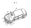
-
- B—PERFORMING OPERATIONS; TRANSPORTING
- B60—VEHICLES IN GENERAL
- B60L—PROPULSION OF ELECTRICALLY-PROPELLED VEHICLES; SUPPLYING ELECTRIC POWER FOR AUXILIARY EQUIPMENT OF ELECTRICALLY-PROPELLED VEHICLES; ELECTRODYNAMIC BRAKE SYSTEMS FOR VEHICLES IN GENERAL; MAGNETIC SUSPENSION OR LEVITATION FOR VEHICLES; MONITORING OPERATING VARIABLES OF ELECTRICALLY-PROPELLED VEHICLES; ELECTRIC SAFETY DEVICES FOR ELECTRICALLY-PROPELLED VEHICLES
- B60L15/00—Methods, circuits, or devices for controlling the traction-motor speed of electrically-propelled vehicles
- B60L15/20—Methods, circuits, or devices for controlling the traction-motor speed of electrically-propelled vehicles for control of the vehicle or its driving motor to achieve a desired performance, e.g. speed, torque, programmed variation of speed
-
- B—PERFORMING OPERATIONS; TRANSPORTING
- B60—VEHICLES IN GENERAL
- B60L—PROPULSION OF ELECTRICALLY-PROPELLED VEHICLES; SUPPLYING ELECTRIC POWER FOR AUXILIARY EQUIPMENT OF ELECTRICALLY-PROPELLED VEHICLES; ELECTRODYNAMIC BRAKE SYSTEMS FOR VEHICLES IN GENERAL; MAGNETIC SUSPENSION OR LEVITATION FOR VEHICLES; MONITORING OPERATING VARIABLES OF ELECTRICALLY-PROPELLED VEHICLES; ELECTRIC SAFETY DEVICES FOR ELECTRICALLY-PROPELLED VEHICLES
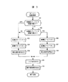
- B60L15/00—Methods, circuits, or devices for controlling the traction-motor speed of electrically-propelled vehicles
- B60L15/20—Methods, circuits, or devices for controlling the traction-motor speed of electrically-propelled vehicles for control of the vehicle or its driving motor to achieve a desired performance, e.g. speed, torque, programmed variation of speed
- B60L15/2009—Methods, circuits, or devices for controlling the traction-motor speed of electrically-propelled vehicles for control of the vehicle or its driving motor to achieve a desired performance, e.g. speed, torque, programmed variation of speed for braking
-
- B—PERFORMING OPERATIONS; TRANSPORTING
- B60—VEHICLES IN GENERAL
- B60L—PROPULSION OF ELECTRICALLY-PROPELLED VEHICLES; SUPPLYING ELECTRIC POWER FOR AUXILIARY EQUIPMENT OF ELECTRICALLY-PROPELLED VEHICLES; ELECTRODYNAMIC BRAKE SYSTEMS FOR VEHICLES IN GENERAL; MAGNETIC SUSPENSION OR LEVITATION FOR VEHICLES; MONITORING OPERATING VARIABLES OF ELECTRICALLY-PROPELLED VEHICLES; ELECTRIC SAFETY DEVICES FOR ELECTRICALLY-PROPELLED VEHICLES
- B60L3/00—Electric devices on electrically-propelled vehicles for safety purposes; Monitoring operating variables, e.g. speed, deceleration or energy consumption
- B60L3/0023—Detecting, eliminating, remedying or compensating for drive train abnormalities, e.g. failures within the drive train
- B60L3/0046—Detecting, eliminating, remedying or compensating for drive train abnormalities, e.g. failures within the drive train relating to electric energy storage systems, e.g. batteries or capacitors
-
- B—PERFORMING OPERATIONS; TRANSPORTING
- B60—VEHICLES IN GENERAL
- B60L—PROPULSION OF ELECTRICALLY-PROPELLED VEHICLES; SUPPLYING ELECTRIC POWER FOR AUXILIARY EQUIPMENT OF ELECTRICALLY-PROPELLED VEHICLES; ELECTRODYNAMIC BRAKE SYSTEMS FOR VEHICLES IN GENERAL; MAGNETIC SUSPENSION OR LEVITATION FOR VEHICLES; MONITORING OPERATING VARIABLES OF ELECTRICALLY-PROPELLED VEHICLES; ELECTRIC SAFETY DEVICES FOR ELECTRICALLY-PROPELLED VEHICLES
- B60L3/00—Electric devices on electrically-propelled vehicles for safety purposes; Monitoring operating variables, e.g. speed, deceleration or energy consumption
- B60L3/04—Cutting off the power supply under fault conditions
-
- B—PERFORMING OPERATIONS; TRANSPORTING
- B60—VEHICLES IN GENERAL
- B60L—PROPULSION OF ELECTRICALLY-PROPELLED VEHICLES; SUPPLYING ELECTRIC POWER FOR AUXILIARY EQUIPMENT OF ELECTRICALLY-PROPELLED VEHICLES; ELECTRODYNAMIC BRAKE SYSTEMS FOR VEHICLES IN GENERAL; MAGNETIC SUSPENSION OR LEVITATION FOR VEHICLES; MONITORING OPERATING VARIABLES OF ELECTRICALLY-PROPELLED VEHICLES; ELECTRIC SAFETY DEVICES FOR ELECTRICALLY-PROPELLED VEHICLES
- B60L50/00—Electric propulsion with power supplied within the vehicle
- B60L50/10—Electric propulsion with power supplied within the vehicle using propulsion power supplied by engine-driven generators, e.g. generators driven by combustion engines
- B60L50/16—Electric propulsion with power supplied within the vehicle using propulsion power supplied by engine-driven generators, e.g. generators driven by combustion engines with provision for separate direct mechanical propulsion
-
- B—PERFORMING OPERATIONS; TRANSPORTING
- B60—VEHICLES IN GENERAL
- B60L—PROPULSION OF ELECTRICALLY-PROPELLED VEHICLES; SUPPLYING ELECTRIC POWER FOR AUXILIARY EQUIPMENT OF ELECTRICALLY-PROPELLED VEHICLES; ELECTRODYNAMIC BRAKE SYSTEMS FOR VEHICLES IN GENERAL; MAGNETIC SUSPENSION OR LEVITATION FOR VEHICLES; MONITORING OPERATING VARIABLES OF ELECTRICALLY-PROPELLED VEHICLES; ELECTRIC SAFETY DEVICES FOR ELECTRICALLY-PROPELLED VEHICLES
- B60L50/00—Electric propulsion with power supplied within the vehicle
- B60L50/50—Electric propulsion with power supplied within the vehicle using propulsion power supplied by batteries or fuel cells
- B60L50/60—Electric propulsion with power supplied within the vehicle using propulsion power supplied by batteries or fuel cells using power supplied by batteries
- B60L50/66—Arrangements of batteries
-
- B—PERFORMING OPERATIONS; TRANSPORTING
- B60—VEHICLES IN GENERAL
- B60L—PROPULSION OF ELECTRICALLY-PROPELLED VEHICLES; SUPPLYING ELECTRIC POWER FOR AUXILIARY EQUIPMENT OF ELECTRICALLY-PROPELLED VEHICLES; ELECTRODYNAMIC BRAKE SYSTEMS FOR VEHICLES IN GENERAL; MAGNETIC SUSPENSION OR LEVITATION FOR VEHICLES; MONITORING OPERATING VARIABLES OF ELECTRICALLY-PROPELLED VEHICLES; ELECTRIC SAFETY DEVICES FOR ELECTRICALLY-PROPELLED VEHICLES
- B60L58/00—Methods or circuit arrangements for monitoring or controlling batteries or fuel cells, specially adapted for electric vehicles
- B60L58/10—Methods or circuit arrangements for monitoring or controlling batteries or fuel cells, specially adapted for electric vehicles for monitoring or controlling batteries
- B60L58/12—Methods or circuit arrangements for monitoring or controlling batteries or fuel cells, specially adapted for electric vehicles for monitoring or controlling batteries responding to state of charge [SoC]
- B60L58/13—Maintaining the SoC within a determined range
-
- B—PERFORMING OPERATIONS; TRANSPORTING
- B60—VEHICLES IN GENERAL
- B60L—PROPULSION OF ELECTRICALLY-PROPELLED VEHICLES; SUPPLYING ELECTRIC POWER FOR AUXILIARY EQUIPMENT OF ELECTRICALLY-PROPELLED VEHICLES; ELECTRODYNAMIC BRAKE SYSTEMS FOR VEHICLES IN GENERAL; MAGNETIC SUSPENSION OR LEVITATION FOR VEHICLES; MONITORING OPERATING VARIABLES OF ELECTRICALLY-PROPELLED VEHICLES; ELECTRIC SAFETY DEVICES FOR ELECTRICALLY-PROPELLED VEHICLES
- B60L58/00—Methods or circuit arrangements for monitoring or controlling batteries or fuel cells, specially adapted for electric vehicles
- B60L58/10—Methods or circuit arrangements for monitoring or controlling batteries or fuel cells, specially adapted for electric vehicles for monitoring or controlling batteries
- B60L58/12—Methods or circuit arrangements for monitoring or controlling batteries or fuel cells, specially adapted for electric vehicles for monitoring or controlling batteries responding to state of charge [SoC]
- B60L58/14—Preventing excessive discharging
-
- B—PERFORMING OPERATIONS; TRANSPORTING
- B60—VEHICLES IN GENERAL
- B60L—PROPULSION OF ELECTRICALLY-PROPELLED VEHICLES; SUPPLYING ELECTRIC POWER FOR AUXILIARY EQUIPMENT OF ELECTRICALLY-PROPELLED VEHICLES; ELECTRODYNAMIC BRAKE SYSTEMS FOR VEHICLES IN GENERAL; MAGNETIC SUSPENSION OR LEVITATION FOR VEHICLES; MONITORING OPERATING VARIABLES OF ELECTRICALLY-PROPELLED VEHICLES; ELECTRIC SAFETY DEVICES FOR ELECTRICALLY-PROPELLED VEHICLES
- B60L58/00—Methods or circuit arrangements for monitoring or controlling batteries or fuel cells, specially adapted for electric vehicles
- B60L58/10—Methods or circuit arrangements for monitoring or controlling batteries or fuel cells, specially adapted for electric vehicles for monitoring or controlling batteries
- B60L58/12—Methods or circuit arrangements for monitoring or controlling batteries or fuel cells, specially adapted for electric vehicles for monitoring or controlling batteries responding to state of charge [SoC]
- B60L58/15—Preventing overcharging
-
- B—PERFORMING OPERATIONS; TRANSPORTING
- B60—VEHICLES IN GENERAL
- B60L—PROPULSION OF ELECTRICALLY-PROPELLED VEHICLES; SUPPLYING ELECTRIC POWER FOR AUXILIARY EQUIPMENT OF ELECTRICALLY-PROPELLED VEHICLES; ELECTRODYNAMIC BRAKE SYSTEMS FOR VEHICLES IN GENERAL; MAGNETIC SUSPENSION OR LEVITATION FOR VEHICLES; MONITORING OPERATING VARIABLES OF ELECTRICALLY-PROPELLED VEHICLES; ELECTRIC SAFETY DEVICES FOR ELECTRICALLY-PROPELLED VEHICLES
- B60L58/00—Methods or circuit arrangements for monitoring or controlling batteries or fuel cells, specially adapted for electric vehicles
- B60L58/10—Methods or circuit arrangements for monitoring or controlling batteries or fuel cells, specially adapted for electric vehicles for monitoring or controlling batteries
- B60L58/18—Methods or circuit arrangements for monitoring or controlling batteries or fuel cells, specially adapted for electric vehicles for monitoring or controlling batteries of two or more battery modules
- B60L58/20—Methods or circuit arrangements for monitoring or controlling batteries or fuel cells, specially adapted for electric vehicles for monitoring or controlling batteries of two or more battery modules having different nominal voltages
-
- B—PERFORMING OPERATIONS; TRANSPORTING
- B60—VEHICLES IN GENERAL
- B60L—PROPULSION OF ELECTRICALLY-PROPELLED VEHICLES; SUPPLYING ELECTRIC POWER FOR AUXILIARY EQUIPMENT OF ELECTRICALLY-PROPELLED VEHICLES; ELECTRODYNAMIC BRAKE SYSTEMS FOR VEHICLES IN GENERAL; MAGNETIC SUSPENSION OR LEVITATION FOR VEHICLES; MONITORING OPERATING VARIABLES OF ELECTRICALLY-PROPELLED VEHICLES; ELECTRIC SAFETY DEVICES FOR ELECTRICALLY-PROPELLED VEHICLES
- B60L58/00—Methods or circuit arrangements for monitoring or controlling batteries or fuel cells, specially adapted for electric vehicles
- B60L58/10—Methods or circuit arrangements for monitoring or controlling batteries or fuel cells, specially adapted for electric vehicles for monitoring or controlling batteries
- B60L58/18—Methods or circuit arrangements for monitoring or controlling batteries or fuel cells, specially adapted for electric vehicles for monitoring or controlling batteries of two or more battery modules
- B60L58/21—Methods or circuit arrangements for monitoring or controlling batteries or fuel cells, specially adapted for electric vehicles for monitoring or controlling batteries of two or more battery modules having the same nominal voltage
-
- B—PERFORMING OPERATIONS; TRANSPORTING
- B60—VEHICLES IN GENERAL
- B60L—PROPULSION OF ELECTRICALLY-PROPELLED VEHICLES; SUPPLYING ELECTRIC POWER FOR AUXILIARY EQUIPMENT OF ELECTRICALLY-PROPELLED VEHICLES; ELECTRODYNAMIC BRAKE SYSTEMS FOR VEHICLES IN GENERAL; MAGNETIC SUSPENSION OR LEVITATION FOR VEHICLES; MONITORING OPERATING VARIABLES OF ELECTRICALLY-PROPELLED VEHICLES; ELECTRIC SAFETY DEVICES FOR ELECTRICALLY-PROPELLED VEHICLES
- B60L7/00—Electrodynamic brake systems for vehicles in general
- B60L7/10—Dynamic electric regenerative braking
- B60L7/14—Dynamic electric regenerative braking for vehicles propelled by AC motors
-
- H—ELECTRICITY
- H02—GENERATION; CONVERSION OR DISTRIBUTION OF ELECTRIC POWER
- H02J—ELECTRIC POWER NETWORKS; CIRCUIT ARRANGEMENTS OR SYSTEMS FOR SUPPLYING OR DISTRIBUTING ELECTRIC POWER; SYSTEMS FOR STORING ELECTRIC ENERGY
- H02J7/00—Circuit arrangements for charging or discharging batteries or for supplying loads from batteries
- H02J7/14—Circuit arrangements for charging or discharging batteries or for supplying loads from batteries for charging batteries from dynamo-electric generators driven at varying speed, e.g. on vehicle
- H02J7/1423—Circuit arrangements for charging or discharging batteries or for supplying loads from batteries for charging batteries from dynamo-electric generators driven at varying speed, e.g. on vehicle with multiple batteries
-
- B—PERFORMING OPERATIONS; TRANSPORTING
- B60—VEHICLES IN GENERAL
- B60L—PROPULSION OF ELECTRICALLY-PROPELLED VEHICLES; SUPPLYING ELECTRIC POWER FOR AUXILIARY EQUIPMENT OF ELECTRICALLY-PROPELLED VEHICLES; ELECTRODYNAMIC BRAKE SYSTEMS FOR VEHICLES IN GENERAL; MAGNETIC SUSPENSION OR LEVITATION FOR VEHICLES; MONITORING OPERATING VARIABLES OF ELECTRICALLY-PROPELLED VEHICLES; ELECTRIC SAFETY DEVICES FOR ELECTRICALLY-PROPELLED VEHICLES
- B60L2210/00—Converter types
- B60L2210/10—DC to DC converters
-
- B—PERFORMING OPERATIONS; TRANSPORTING
- B60—VEHICLES IN GENERAL
- B60L—PROPULSION OF ELECTRICALLY-PROPELLED VEHICLES; SUPPLYING ELECTRIC POWER FOR AUXILIARY EQUIPMENT OF ELECTRICALLY-PROPELLED VEHICLES; ELECTRODYNAMIC BRAKE SYSTEMS FOR VEHICLES IN GENERAL; MAGNETIC SUSPENSION OR LEVITATION FOR VEHICLES; MONITORING OPERATING VARIABLES OF ELECTRICALLY-PROPELLED VEHICLES; ELECTRIC SAFETY DEVICES FOR ELECTRICALLY-PROPELLED VEHICLES
- B60L2210/00—Converter types
- B60L2210/30—AC to DC converters
-
- B—PERFORMING OPERATIONS; TRANSPORTING
- B60—VEHICLES IN GENERAL
- B60L—PROPULSION OF ELECTRICALLY-PROPELLED VEHICLES; SUPPLYING ELECTRIC POWER FOR AUXILIARY EQUIPMENT OF ELECTRICALLY-PROPELLED VEHICLES; ELECTRODYNAMIC BRAKE SYSTEMS FOR VEHICLES IN GENERAL; MAGNETIC SUSPENSION OR LEVITATION FOR VEHICLES; MONITORING OPERATING VARIABLES OF ELECTRICALLY-PROPELLED VEHICLES; ELECTRIC SAFETY DEVICES FOR ELECTRICALLY-PROPELLED VEHICLES
- B60L2210/00—Converter types
- B60L2210/40—DC to AC converters
-
- B—PERFORMING OPERATIONS; TRANSPORTING
- B60—VEHICLES IN GENERAL
- B60L—PROPULSION OF ELECTRICALLY-PROPELLED VEHICLES; SUPPLYING ELECTRIC POWER FOR AUXILIARY EQUIPMENT OF ELECTRICALLY-PROPELLED VEHICLES; ELECTRODYNAMIC BRAKE SYSTEMS FOR VEHICLES IN GENERAL; MAGNETIC SUSPENSION OR LEVITATION FOR VEHICLES; MONITORING OPERATING VARIABLES OF ELECTRICALLY-PROPELLED VEHICLES; ELECTRIC SAFETY DEVICES FOR ELECTRICALLY-PROPELLED VEHICLES
- B60L2240/00—Control parameters of input or output; Target parameters
- B60L2240/10—Vehicle control parameters
- B60L2240/12—Speed
-
- B—PERFORMING OPERATIONS; TRANSPORTING
- B60—VEHICLES IN GENERAL
- B60L—PROPULSION OF ELECTRICALLY-PROPELLED VEHICLES; SUPPLYING ELECTRIC POWER FOR AUXILIARY EQUIPMENT OF ELECTRICALLY-PROPELLED VEHICLES; ELECTRODYNAMIC BRAKE SYSTEMS FOR VEHICLES IN GENERAL; MAGNETIC SUSPENSION OR LEVITATION FOR VEHICLES; MONITORING OPERATING VARIABLES OF ELECTRICALLY-PROPELLED VEHICLES; ELECTRIC SAFETY DEVICES FOR ELECTRICALLY-PROPELLED VEHICLES
- B60L2240/00—Control parameters of input or output; Target parameters
- B60L2240/40—Drive Train control parameters
- B60L2240/42—Drive Train control parameters related to electric machines
- B60L2240/421—Speed
-
- B—PERFORMING OPERATIONS; TRANSPORTING
- B60—VEHICLES IN GENERAL
- B60L—PROPULSION OF ELECTRICALLY-PROPELLED VEHICLES; SUPPLYING ELECTRIC POWER FOR AUXILIARY EQUIPMENT OF ELECTRICALLY-PROPELLED VEHICLES; ELECTRODYNAMIC BRAKE SYSTEMS FOR VEHICLES IN GENERAL; MAGNETIC SUSPENSION OR LEVITATION FOR VEHICLES; MONITORING OPERATING VARIABLES OF ELECTRICALLY-PROPELLED VEHICLES; ELECTRIC SAFETY DEVICES FOR ELECTRICALLY-PROPELLED VEHICLES
- B60L2240/00—Control parameters of input or output; Target parameters
- B60L2240/40—Drive Train control parameters
- B60L2240/42—Drive Train control parameters related to electric machines
- B60L2240/423—Torque
-
- B—PERFORMING OPERATIONS; TRANSPORTING
- B60—VEHICLES IN GENERAL
- B60L—PROPULSION OF ELECTRICALLY-PROPELLED VEHICLES; SUPPLYING ELECTRIC POWER FOR AUXILIARY EQUIPMENT OF ELECTRICALLY-PROPELLED VEHICLES; ELECTRODYNAMIC BRAKE SYSTEMS FOR VEHICLES IN GENERAL; MAGNETIC SUSPENSION OR LEVITATION FOR VEHICLES; MONITORING OPERATING VARIABLES OF ELECTRICALLY-PROPELLED VEHICLES; ELECTRIC SAFETY DEVICES FOR ELECTRICALLY-PROPELLED VEHICLES
- B60L2240/00—Control parameters of input or output; Target parameters
- B60L2240/40—Drive Train control parameters
- B60L2240/44—Drive Train control parameters related to combustion engines
- B60L2240/441—Speed
-
- B—PERFORMING OPERATIONS; TRANSPORTING
- B60—VEHICLES IN GENERAL
- B60L—PROPULSION OF ELECTRICALLY-PROPELLED VEHICLES; SUPPLYING ELECTRIC POWER FOR AUXILIARY EQUIPMENT OF ELECTRICALLY-PROPELLED VEHICLES; ELECTRODYNAMIC BRAKE SYSTEMS FOR VEHICLES IN GENERAL; MAGNETIC SUSPENSION OR LEVITATION FOR VEHICLES; MONITORING OPERATING VARIABLES OF ELECTRICALLY-PROPELLED VEHICLES; ELECTRIC SAFETY DEVICES FOR ELECTRICALLY-PROPELLED VEHICLES
- B60L2240/00—Control parameters of input or output; Target parameters
- B60L2240/40—Drive Train control parameters
- B60L2240/44—Drive Train control parameters related to combustion engines
- B60L2240/443—Torque
-
- B—PERFORMING OPERATIONS; TRANSPORTING
- B60—VEHICLES IN GENERAL
- B60L—PROPULSION OF ELECTRICALLY-PROPELLED VEHICLES; SUPPLYING ELECTRIC POWER FOR AUXILIARY EQUIPMENT OF ELECTRICALLY-PROPELLED VEHICLES; ELECTRODYNAMIC BRAKE SYSTEMS FOR VEHICLES IN GENERAL; MAGNETIC SUSPENSION OR LEVITATION FOR VEHICLES; MONITORING OPERATING VARIABLES OF ELECTRICALLY-PROPELLED VEHICLES; ELECTRIC SAFETY DEVICES FOR ELECTRICALLY-PROPELLED VEHICLES
- B60L2250/00—Driver interactions
- B60L2250/26—Driver interactions by pedal actuation
-
- B—PERFORMING OPERATIONS; TRANSPORTING
- B60—VEHICLES IN GENERAL
- B60L—PROPULSION OF ELECTRICALLY-PROPELLED VEHICLES; SUPPLYING ELECTRIC POWER FOR AUXILIARY EQUIPMENT OF ELECTRICALLY-PROPELLED VEHICLES; ELECTRODYNAMIC BRAKE SYSTEMS FOR VEHICLES IN GENERAL; MAGNETIC SUSPENSION OR LEVITATION FOR VEHICLES; MONITORING OPERATING VARIABLES OF ELECTRICALLY-PROPELLED VEHICLES; ELECTRIC SAFETY DEVICES FOR ELECTRICALLY-PROPELLED VEHICLES
- B60L2260/00—Operating Modes
- B60L2260/20—Drive modes; Transition between modes
- B60L2260/26—Transition between different drive modes
-
- F—MECHANICAL ENGINEERING; LIGHTING; HEATING; WEAPONS; BLASTING
- F02—COMBUSTION ENGINES; HOT-GAS OR COMBUSTION-PRODUCT ENGINE PLANTS
- F02N—STARTING OF COMBUSTION ENGINES; STARTING AIDS FOR SUCH ENGINES, NOT OTHERWISE PROVIDED FOR
- F02N11/00—Starting of engines by means of electric motors
- F02N11/08—Circuits specially adapted for starting of engines
- F02N11/0862—Circuits specially adapted for starting of engines characterised by the electrical power supply means, e.g. battery
- F02N11/0866—Circuits specially adapted for starting of engines characterised by the electrical power supply means, e.g. battery comprising several power sources, e.g. battery and capacitor or two batteries
-
- F—MECHANICAL ENGINEERING; LIGHTING; HEATING; WEAPONS; BLASTING
- F02—COMBUSTION ENGINES; HOT-GAS OR COMBUSTION-PRODUCT ENGINE PLANTS
- F02N—STARTING OF COMBUSTION ENGINES; STARTING AIDS FOR SUCH ENGINES, NOT OTHERWISE PROVIDED FOR
- F02N11/00—Starting of engines by means of electric motors
- F02N11/08—Circuits specially adapted for starting of engines
- F02N2011/0881—Components of the circuit not provided for by previous groups
- F02N2011/0888—DC/DC converters
-
- F—MECHANICAL ENGINEERING; LIGHTING; HEATING; WEAPONS; BLASTING
- F02—COMBUSTION ENGINES; HOT-GAS OR COMBUSTION-PRODUCT ENGINE PLANTS
- F02N—STARTING OF COMBUSTION ENGINES; STARTING AIDS FOR SUCH ENGINES, NOT OTHERWISE PROVIDED FOR
- F02N11/00—Starting of engines by means of electric motors
- F02N11/08—Circuits specially adapted for starting of engines
- F02N2011/0881—Components of the circuit not provided for by previous groups
- F02N2011/0896—Inverters for electric machines, e.g. starter-generators
-
- Y—GENERAL TAGGING OF NEW TECHNOLOGICAL DEVELOPMENTS; GENERAL TAGGING OF CROSS-SECTIONAL TECHNOLOGIES SPANNING OVER SEVERAL SECTIONS OF THE IPC; TECHNICAL SUBJECTS COVERED BY FORMER USPC CROSS-REFERENCE ART COLLECTIONS [XRACs] AND DIGESTS
- Y02—TECHNOLOGIES OR APPLICATIONS FOR MITIGATION OR ADAPTATION AGAINST CLIMATE CHANGE
- Y02T—CLIMATE CHANGE MITIGATION TECHNOLOGIES RELATED TO TRANSPORTATION
- Y02T10/00—Road transport of goods or passengers
- Y02T10/60—Other road transportation technologies with climate change mitigation effect
- Y02T10/62—Hybrid vehicles
-
- Y—GENERAL TAGGING OF NEW TECHNOLOGICAL DEVELOPMENTS; GENERAL TAGGING OF CROSS-SECTIONAL TECHNOLOGIES SPANNING OVER SEVERAL SECTIONS OF THE IPC; TECHNICAL SUBJECTS COVERED BY FORMER USPC CROSS-REFERENCE ART COLLECTIONS [XRACs] AND DIGESTS
- Y02—TECHNOLOGIES OR APPLICATIONS FOR MITIGATION OR ADAPTATION AGAINST CLIMATE CHANGE
- Y02T—CLIMATE CHANGE MITIGATION TECHNOLOGIES RELATED TO TRANSPORTATION
- Y02T10/00—Road transport of goods or passengers
- Y02T10/60—Other road transportation technologies with climate change mitigation effect
- Y02T10/64—Electric machine technologies in electromobility
-
- Y—GENERAL TAGGING OF NEW TECHNOLOGICAL DEVELOPMENTS; GENERAL TAGGING OF CROSS-SECTIONAL TECHNOLOGIES SPANNING OVER SEVERAL SECTIONS OF THE IPC; TECHNICAL SUBJECTS COVERED BY FORMER USPC CROSS-REFERENCE ART COLLECTIONS [XRACs] AND DIGESTS
- Y02—TECHNOLOGIES OR APPLICATIONS FOR MITIGATION OR ADAPTATION AGAINST CLIMATE CHANGE
- Y02T—CLIMATE CHANGE MITIGATION TECHNOLOGIES RELATED TO TRANSPORTATION
- Y02T10/00—Road transport of goods or passengers
- Y02T10/60—Other road transportation technologies with climate change mitigation effect
- Y02T10/70—Energy storage systems for electromobility, e.g. batteries
-
- Y—GENERAL TAGGING OF NEW TECHNOLOGICAL DEVELOPMENTS; GENERAL TAGGING OF CROSS-SECTIONAL TECHNOLOGIES SPANNING OVER SEVERAL SECTIONS OF THE IPC; TECHNICAL SUBJECTS COVERED BY FORMER USPC CROSS-REFERENCE ART COLLECTIONS [XRACs] AND DIGESTS
- Y02—TECHNOLOGIES OR APPLICATIONS FOR MITIGATION OR ADAPTATION AGAINST CLIMATE CHANGE
- Y02T—CLIMATE CHANGE MITIGATION TECHNOLOGIES RELATED TO TRANSPORTATION
- Y02T10/00—Road transport of goods or passengers
- Y02T10/60—Other road transportation technologies with climate change mitigation effect
- Y02T10/7072—Electromobility specific charging systems or methods for batteries, ultracapacitors, supercapacitors or double-layer capacitors
-
- Y—GENERAL TAGGING OF NEW TECHNOLOGICAL DEVELOPMENTS; GENERAL TAGGING OF CROSS-SECTIONAL TECHNOLOGIES SPANNING OVER SEVERAL SECTIONS OF THE IPC; TECHNICAL SUBJECTS COVERED BY FORMER USPC CROSS-REFERENCE ART COLLECTIONS [XRACs] AND DIGESTS
- Y02—TECHNOLOGIES OR APPLICATIONS FOR MITIGATION OR ADAPTATION AGAINST CLIMATE CHANGE
- Y02T—CLIMATE CHANGE MITIGATION TECHNOLOGIES RELATED TO TRANSPORTATION
- Y02T10/00—Road transport of goods or passengers
- Y02T10/60—Other road transportation technologies with climate change mitigation effect
- Y02T10/72—Electric energy management in electromobility
-
- Y—GENERAL TAGGING OF NEW TECHNOLOGICAL DEVELOPMENTS; GENERAL TAGGING OF CROSS-SECTIONAL TECHNOLOGIES SPANNING OVER SEVERAL SECTIONS OF THE IPC; TECHNICAL SUBJECTS COVERED BY FORMER USPC CROSS-REFERENCE ART COLLECTIONS [XRACs] AND DIGESTS
- Y10—TECHNICAL SUBJECTS COVERED BY FORMER USPC
- Y10S—TECHNICAL SUBJECTS COVERED BY FORMER USPC CROSS-REFERENCE ART COLLECTIONS [XRACs] AND DIGESTS
- Y10S903/00—Hybrid electric vehicles, HEVS
- Y10S903/902—Prime movers comprising electrical and internal combustion motors
- Y10S903/903—Prime movers comprising electrical and internal combustion motors having energy storing means, e.g. battery, capacitor
Landscapes
- Engineering & Computer Science (AREA)
- Mechanical Engineering (AREA)
- Transportation (AREA)
- Power Engineering (AREA)
- Sustainable Energy (AREA)
- Life Sciences & Earth Sciences (AREA)
- Sustainable Development (AREA)
- Chemical & Material Sciences (AREA)
- Combustion & Propulsion (AREA)
- Electric Propulsion And Braking For Vehicles (AREA)
- Hybrid Electric Vehicles (AREA)
- Control Of Eletrric Generators (AREA)
- Charge And Discharge Circuits For Batteries Or The Like (AREA)
Description
【0001】
【発明の属する技術分野】
本発明は、自動車内の使用電力の増大に対応するために複数の異なる電圧を必要とする自動車、およびその電源装置に係り、特に複数電圧電源を低コストで実現するのに好適な技術に関する。
【0002】
【従来の技術】
電動パワステや電動エアコンなど自動車搭載機器の電動化,大容量化に対応するため、従来の14V系電源に42V系電源を加えた42V自動車電源システムが提案されている。42V系電源では電圧が従来の3倍となるため電流が3分の1で済み、損失低減やハーネスの軽量化,大電力負荷の採用などが期待できる。
【0003】
しかし、電力負荷の中にはランプ系など42V化が難しいものもあるため、当面は42Vと14Vの2種類の電圧が混在する形になることが予想される。
【0004】
そこで、42V用バッテリ(定格36V)と14V用バッテリ(定格12V)の両方を備え、オルタネータから42V用バッテリに充電し、14V用バッテリへはDC/DCコンバータを介して充電する方式が提案されている。
【0005】
また、コスト低減策として、オルタネータの出力を42V側または14V側にスイッチで切り換えることにより、DC/DCコンバータを省略する方式も提案されている。
【0006】
さらには、2つのバッテリを直列に接続して2種類の電圧端子を設け、スイッチング素子の切り換えにより各バッテリの充電を切り換える方式もある。これを42V電源に適用すれば、42V用バッテリに14V端子を持たせられるため、14V用バッテリを別に用意する必要がなくなる。この方式の記載例として、米国特許第4,686,442号がある。
【0007】
また、オルタネータの効率向上やスタータの寿命向上を目的として、スタータとオルタネータの機能を一体化しインバータで制御するモータ/ジェネレータを42V電源に適用する方式も考えられている。
【0008】
【発明が解決しようとする課題】
上記の方式のうち、オルタネータの出力を42V側または14V側にスイッチで切り換える方式では、スイッチを制御するコントローラが故障してスイッチをオンすることができなくなった場合、バッテリに全く充電することができなくなるという問題がある。また、42V用バッテリとは別に14V用バッテリを備える必要があり、コストが高くなってしまう。
【0009】
2つのバッテリを直列に接続して2種類の電圧端子を設け、スイッチング素子の切り換えにより各バッテリの充電を切り換える方式では、オルタネータからの充電方向のみを考慮したスイッチング素子構成になっており、放電方向には電流が流せないため、スタータの機能を一体化させたモータ/ジェネレータには適用できないという問題がある。
【0010】
また、どちらの例においてもスイッチを切り換える際の電源電圧の変化については考慮されていない。
【0011】
本発明の目的の一つは、DC/DCコンバータを用いず、かつバッテリを複数個必要とせず、さらにスイッチを制御するコントローラが故障しても動作可能な自動車、およびその電源装置を提供することである。
【0012】
また、本発明の他の目的は、スイッチを切り換える際の電源電圧の変動が少なくなるように制御可能な自動車、およびその電源装置を提供することである。
【0013】
【課題を解決するための手段】
本発明は、高電圧端子と低電圧端子とを有するバッテリと、交流電力を直流電力に変換する変換器と、バッテリの高電圧端子から変換器への一方向の電力供給を制御する第1のスイッチング素子と、変換器からバッテリの低電圧端子への一方向の電力供給を制御する第2のスイッチング素子とを有する自動車の電源装置である。
【0014】
この構成により、DC/DCコンバータを用いなくても複数電圧の電源系が実現できる。
【0015】
また、1つのバッテリに複数電圧の端子を設けたため、電圧ごとに別々のバッテリを用意する必要がない。
【0016】
本発明の好ましくは、第1及び第2のスイッチング素子は、電界効果トランジスタと逆接続のダイオードにより構成することである。
【0017】
また本発明の好ましくは、第1及び第2のスイッチング素子の状態に応じて、変換器の直流側電圧を選択し、選択した直流側電圧に基づいて変換器を制御することである。
【0018】
また本発明の好ましくは、コントローラなどの故障により第1または第2のスイッチング素子が制御できない場合には、変換器への要求電力の方向に応じて、変換器の直流側電圧を選択し、選択した直流側電圧に基づいて変換器を制御することである。
【0019】
このことによりスイッチング素子が制御不能となった場合でも、逆接続ダイオードの働きにより、高電圧端子側への充電、及び低電圧端子側からの放電は常に可能であり、低電圧端子側のバッテリ残存量がなくなるまで自動車を動作させることができる。
【0020】
また、本発明の好ましくは、高電圧端子側のバッテリ充電率、及び低電圧端子側のバッテリ充電率をそれぞれ検知する充電率検出手段を備え、充電率検出手段が検出したバッテリの高電圧端子側の充電率と、充電率検出手段が検出したバッテリの低電圧端子側の充電率との差に応じて第1及び第2のスイッチング素子を制御することである。
【0021】
これにより、高電圧端子側と低電圧端子側とでバッテリ充電率にアンバランスが生じないように制御することができ、充電率のアンバランスによるバッテリ性能の低下を防ぐことができる。
【0022】
また、本発明の好ましくは、変換器により直流電圧を制御する際に、直接制御していない他の電圧端子の電圧を検出して、電圧制御系に補正を加えることである。
【0023】
これにより、スイッチング素子を切り換えても端子電圧が大きく変化しないような制御が可能となる。
【0024】
また本発明は、モータ/ジェネレータと、前記モータ/ジェネレータを駆動するインバータと、複数の異なる電圧の端子を介して前記インバータに接続されたバッテリと、前記バッテリの複数の異なる電圧の端子のうち所定の第1の端子と前記インバータの間に設けられた第1のスイッチング素子と、前記第1のスイッチング素子の内部に断続切換手段と並列に設けられ、前記インバータから前記第1の端子への方向へより多く電流を流す第1の整流素子と、前記バッテリの複数の異なる電圧の端子のうち前記第1の端子よりも低電圧の第2の端子と前記インバータの間に設けられた第2のスイッチング素子と、前記第2のスイッチング素子の内部に断続切換手段と並列に設けられ、前記第2の端子から前記インバータの方向へより多く電流を流す第2の整流素子と、前記バッテリの充電状態に応じて前記第1及び第2のスイッチング素子をオン・オフするバッテリ制御装置と、を有する自動車である。
【0025】
また本発明の好ましくは、前記第1のスイッチング素子と第1の整流器、および前記第2のスイッチング素子と第2の整流器は、それぞれ第1の電界効果トランジスタ、および第2の電界効果トランジスタである自動車である。
【0026】
【発明の実施の形態】
以下、本発明の実施の形態を図面を参照して説明する。
【0027】
図1は42V系と14V系の2つの電圧系を備えた自動車電源の構成例を示したものである。エンジン1の回転軸上にモータ/ジェネレータ2が接続されており、エンジン1の始動や発電を行う。モータ/ジェネレータ2の駆動力および発電電力はインバータ3により制御される。エンジン始動の場合は、バッテリ6の直流電圧をインバータ3で交流電圧に変換し、モータ/ジェネレータ2が駆動トルクを発生してエンジン1を回転させる。エンジン1が始動すれば、その回転によってモータ/ジェネレータ2に交流電圧が発生する。これをインバータ3で直流電圧に変換し、バッテリ6に充電する。
【0028】
バッテリ6は42V用(定格36V)で、42V用の高電圧端子11とアース端子13とを備えている。さらに、14V系負荷に電力供給するために14V用の低電圧端子12も備えている。バッテリの構成としては一体型構成でも良いし、あるいは14V用(定格12V)のバッテリブロックを3つ直列につないだ形で構成しても良い。バッテリブロックを3つ直列につないだ構成の場合には、直列の順序を一定期間ごとに入れ換えたり、ブロック単位で交換したりできるという利点がある。また、28V用(定格24V)のバッテリと14V用のバッテリを組み合わせて構成しても良い。
【0029】
42V用の高電圧端子11には、電動パワステ,電動エアコンなど比較的大電力の42V系負荷21が複数接続される。14V用の低電圧端子12には、主にランプ類や種々のコントローラなど低電圧の方が有利な14V系負荷22が複数接続される。また、高電圧端子11と低電圧端子12の間の電圧は28Vになるので、この2端子間に28V用の負荷をつなぐことも可能である。
【0030】
インバータ3とバッテリ6の間は次のように接続する。まず、インバータ3の負極側はバッテリ6のアース端子13に接続する。インバータ3の正極とバッテリ6の高電圧端子11の間には第1のスイッチング素子である高電圧FET(電界効果トランジスタ)4を、インバータ3の正極とバッテリ6の低電圧端子12の間には第2のスイッチング素子である低電圧FET5をそれぞれ接続する。高電圧FET4のソースを高電圧端子11に、ドレインをインバータ3に接続する。なお高電圧FET4に内蔵している逆接続ダイオード(整流器)により、インバータ3から高電圧端子11への電流はスイッチがオフでも流すことができる。低電圧FET5のソースはインバータ3の正極に、ドレインは低電圧端子12に接続する。低電圧FET5に内蔵しているダイオードにより、バッテリ6の低電圧端子12からインバータ3への電流はスイッチがオフでも流すことができる。
【0031】
すなわち、高電圧FET4はバッテリ6の高電圧端子11からインバータ3への一方向の電力供給を制御するスイッチング素子として作用し、また低電圧FET5はインバータ3からバッテリ6の低電圧端子12への一方向の電力供給を制御するスイッチング素子として作用する。これらのFETは、内部に回路を断続する断続切換手段と、それと並列に設けられた整流素子で構成されている。
【0032】
統合制御装置9は、運転者のキースイッチ操作,アクセル操作,ブレーキ操作,及びバッテリ充電率などに基づいて、エンジン始動,充電,アシスト,回生などの動作モード指令をバッテリ制御装置7に対して与える。また、モータ/ジェネレータ2が出すべきトルクの指令τoを出力する。
【0033】
バッテリ制御装置7は、バッテリ6の充電状態に応じてスイッチング素子である高電圧FET4及び低電圧FET5を制御する。ここでは、高電圧FET4および低電圧FET5のゲート電圧を操作してスイッチングを達成する。また、スイッチの状態に対応してモータ制御装置8に電圧選択信号を与える。また、統合制御装置9からの指令に基づいて、モータ/ジェネレータ2が発生すべき駆動トルク、または発電トルクを決定し、モータ制御装置8にトルク指令τmを与える。さらに、バッテリ制御装置7自身が正常に動作しているかを示す動作確認信号を出力する。
【0034】
モータ制御装置8は、バッテリ制御装置7からの電圧選択信号,トルク指令及びエンジン1のクランク角信号θcに基づいて、インバータ3に対してPWM信号Pu,Pv,Pwを出力する。また、バッテリ制御装置7からの動作確認信号を入力し、もしバッテリ制御装置7が正常に動作していない場合には、異常時の特殊処理を行う。
【0035】
図1の自動車搭載例を図8に示す。
【0036】
図8において、モータ/ジェネレータ2はエンジン1の外側に横置き方式で搭載されており、クランク軸プーリ103との間にベルト81が掛け渡され、これによりエンジン1と双方向の駆動力伝達が行われる。尚、モータ/ジェネレータ2の配置はエンジン1の配置の都合により適宜最適化することができ、エンジンに対して縦置きであるか横置きであるか限定されるものではない。
【0037】
また、モータ/ジェネレータ2以外のバッテリ6,インバータ3,バッテリ制御装置7,モータ制御装置8,統合制御装置9のような装置,機器等もエンジンルーム105内に配置されているが、その詳細については図示しない車両関連機器の配置の都合により適宜最適化することができ、さらにエンジンルーム105以外の場所に配置することも可能である。さらにはバッテリ制御装置7,モータ制御装置8、および統合制御装置9も一つの筐体として図示しているが、別筐体であることを妨げるものではなく、またインバータ3を他の制御装置と同一の筐体に収めて配置することも可能である。
【0038】
尚、本実施例ではエンジン101とモータ/ジェネレータ2はベルト81を介して機械的に連結されているが、これ以外にも例えばエンジン101のクランク軸102とモータ/ジェネレータ2の回転子が直結されている構成をとっても良く、さらに種々の連結構成を採用できることは言うまでもない。
【0039】
以下、バッテリ制御装置7の構成と動作について詳しく説明する。
【0040】
図2はバッテリ制御装置7の構成を示したものである。まず、高電圧側充電率測定部54が、電流検出手段14及び電圧検出手段16の出力をもとに高電圧側バッテリの充電率を測定する。同様に低電圧側充電率測定部55が、電流検出手段14,15及び電圧検出手段17の出力をもとに低電圧側バッテリの充電率を測定する。高電圧側バッテリの充電率は統合制御装置9に出力される。なお、高電圧側バッテリとは高電圧端子11と低電圧端子12の間のバッテリブロックを、低電圧側バッテリとは低電圧端子12とアース端子13の間のバッテリブロックのことを指すものとする。
【0041】
充電率の測定方法としては様々なものがあるが、ここではバッテリに流れる電流の積算値と電圧・電流値とから、あらかじめ求めた特性データに従って定めるものとした。鉛,ニッケル水素,リチウムイオンなど、電池の種類によってそれぞれに適した測定手段があるので、それらを適宜用いるようにすればよい。
【0042】
なお、低電圧バッテリに流れる電流は、42V側の電流検出手段14と14V側の電流検出手段15のそれぞれの電流を合計したものになることに注意する必要がある。
【0043】
以上の方法で求めたバッテリの充電率と電圧検出値とに基づいて実際の制御を行う。統合制御装置9から出力された動作モードに応じて、エンジン始動制御部51,充電制御部52,回生・アシスト制御部53のいずれかが作動し、制御信号を出力する。
【0044】
まずはじめにエンジン始動の場合について説明する。運転者のキースイッチ操作に基づいてエンジン始動指令が動作モード信号として統合制御装置9から出力されると、エンジン始動制御部51が作動して制御を行う。アイドルストップ機能を備えた自動車の場合には、キースイッチ操作の他に、シフト操作やブレーキ操作,アクセル操作などに基づいてエンジン始動指令が出力される。
【0045】
エンジン始動制御部の処理フローを図3に示す。まず、高電圧バッテリで始動可能かどうかを調べる(ステップ101)。始動可能かどうかは、高電圧側充電率測定部55が測定した充電率がある値以上かどうか、あるいは高電圧系(42V系)の電圧値がある値以上かどうかで判定する。電池の充電率が小さくても他の自動車の電池が接続されて電圧がある値以上になっていれば、いわゆるジャンプスタートによる始動が可能と判断する。始動可能であれば、ステップ103〜105に進み、低電圧FET5をオフ,高電圧FET4をオンとし、42Vを選択したことを電圧選択信号として出力する。
【0046】
高電圧バッテリで始動可能と判定できなかった場合には、ステップ102に進んで低電圧バッテリで始動可能かどうかをチェックする。ステップ101と同様に、低電圧バッテリの充電率がある値以上かどうか、あるいは低電圧系(14V系)の電圧値がある値以上かどうかで判定する。始動可能であれば、ステップ106〜108に進み、高電圧FET4をオフ,低電圧FET5をオンとし、14Vを選択したことを電圧選択信号として出力する。
【0047】
低電圧バッテリでも始動可能と判定できなかった場合、この例ではステップ103に進み、高電圧バッテリでの始動を試すこととした。電池の過放電を避けたい場合には、ステップ103に進まず、エンジン始動不能という表示をしてエンジン始動をあきらめ、他の自動車の電池を用いたジャンプスタートを促すという方法もある。
【0048】
電圧選択信号が出力されると、次にステップ109に進んでトルク指令を出力する。エンジン始動の場合は、トルク指令値τmは統合制御装置9から出力された指令τoをそのまま用いることとする。最後に、バッテリ制御装置自身が正常に動作しているかどうかを示す動作確認信号を出力する(ステップ110)。
【0049】
このように本実施例によれば、どちらの電圧から始動が可能かを判定して電圧を切り換えるため、確実にエンジン始動ができるという特長がある。また、他の自動車のバッテリを用いたジャンプスタートについても、42V,14Vどちらの電圧からでも始動が可能で、しかも電圧の判定が自動的に行えるという効果がある。
【0050】
次に、エンジン1が始動してモータ/ジェネレータ2によりバッテリの充電を行う場合について説明する。統合制御装置9からは、エンジンが回転していることを確認して、充電指令が動作モード信号として出力される。なお、回生制動機能を持つ自動車の場合には、バッテリの充電率が100%になっていると回生ができないため、充電率を例えば90%程度以下に保つよう、充電率情報を考慮して充電の指令を出力する。
【0051】
バッテリ制御装置7では、充電制御部52が作動して、図4のフローに従って充電の制御を行う。充電を行う際、高電圧側バッテリと低電圧バッテリの充電率に大きなアンバランスが生じないように高電圧FET4と低電圧FET5とを制御する必要がある。ここでは、高電圧バッテリの充電率と低電圧バッテリの充電率との差をΔSOCとし、このΔSOCが±5%の間に収まるように制御するものとする。
【0052】
まずステップ201で、ΔSOCが−5%より小さくなっていないかどうかをチェックする。もし小さければ、高電圧側バッテリの充電率が大きくなるように低電圧FET5をオフ,高電圧FET4をオンとしてインバータ3を42V系に接続する(ステップ204〜205)。ステップ206で、電圧選択信号として42Vを選択したことを出力して、ステップ209に進む。ΔSOCが−5%以上であれば、ステップ202に進んでΔSOCが+5%よりも大きくないかどうかを調べる。もし+5%よりも大きければ、低電圧側バッテリの充電率が上がるように、高電圧FET4をオフ,低電圧FET5をオンとして、インバータ3を14V系に接続し、電圧選択信号として14Vを出力して(ステップ206〜208)、ステップ209に進む。もしΔSOCが+5%以下であれば、スイッチの変更は何も行わず、ステップ209へ進む。ステップ209ではモータ/ジェネレータ2が発生すべき充電トルクを演算する。演算したトルクをステップ210で出力し、最後にステップ211で動作確認信号を出力する。
【0053】
以上の方法によれば、高電圧側バッテリと低電圧バッテリの充電率の差が常に設定した値以内になるように制御されるので、バッテリブロック間の充電率のアンバランスによるバッテリ性能の低下を防ぐことができる。
なお、ΔSOCだけでなく、エンジン回転数も考慮してスイッチを切り換える方法もある。エンジン回転数が高いときにはモータ/ジェネレータ2の誘起電圧が高くなるのでインバータを42V系に接続し、逆にエンジン回転数が小さいときには14V系に接続する。これによりモータの誘起電圧に合った電圧を選択できるため、発電効率を高めることができるという効果がある。
【0054】
また、図4のフローではΔSOCがある範囲内に収まるように制御したが、もっと頻繁にスイッチを切り換えればΔSOCをほぼ0に保つよう制御することも可能である。例えば、10msといったある制御周期の間で必ず高電圧FET4と低電圧FET5のオンオフ切り換えを行うようにし、高電圧FET4がオンになっている期間をΔSOCに応じて変化させる。ΔSOCが正ならば高電圧FET4がオンになっている期間を長くし、逆にΔSOCが負ならば高電圧FET4がオンになっている期間を短くする。期間を変化させる度合い(ゲイン)を調整すれば、常にΔSOCをほぼ0に保つような制御が可能となる。
【0055】
ステップ209ではモータ/ジェネレータ2が出すべき発電トルクを演算するが、演算方法の一例として直流電圧を目標値に保つ方法について図5を用いて説明する。例えばインバータが42V系に接続されている場合、42V系の電圧目標値と電圧検出値との差に基づいて充電トルクを算出する。電圧検出値の方が低い場合には、充電トルクを増加させることにより電池に流れる充電電流が大きくなり、42V系の電圧も上昇する。制御方法としては例えば比例積分制御(PI制御)を用いればよい。その際、14V系についても電圧目標値と電圧検出値の差をとり、補正ゲインをかけて42V系の電圧目標値に加えるようにする。14V系にはランプ負荷など電圧変化が好ましくない負荷が接続されるため、スイッチを切り換えた際にも電圧が変化しないように制御することが重要である。図5に示す方法を用いれば、インバータを42V系につないだ場合でも、14V系の電圧を目標値近くに保つように制御することができる。
【0056】
次に、動作モードとして回生制動またはエンジンアシストが指令された場合について説明する。この場合、回生・アシスト制御部53が作動して制御を行う。回生制動,エンジンアシストともに大きな電力がバッテリから充電または放電される可能性が高いため、基本的には低電圧スイッチ5をオフ,高電圧スイッチ4をオンとし、インバータを高電圧側に接続する。トルク指令としては統合制御装置9が出力したトルク指令値τoをそのまま出力する。処理ステップとしては、図3のステップ103〜105及びステップ109〜110と同様の処理を行えばよい。
【0057】
次に、モータ制御装置8の動作について説明する。
【0058】
図6は、モータ/ジェネレータ2として誘導機を用いた場合の制御ブロックを示したものである。まず、バッテリ制御装置7から出力されたトルク指令値τmをもとに、モータ/ジェネレータ2のすべり角周波数ωsをすべり制御部35で決定する。なお、バッテリ制御装置7からの動作確認信号によりバッテリ制御装置が異常と判定されたときには、τmではなく統合制御装置9から出力されたトルク指令値τoを用いるようにする。速度検出部34では、エンジン1のクランク角θcからモータ速度ωmを算出する。モータ/ジェネレータ2はエンジン1と直結しているため、クランク角θcでモータ速度ωmを検出すれば、モータ専用に回転センサを用いる必要がない。次にモータ速度ωmとすべり角周波数ωsの和によりインバータ3の1次角周波数ω1を演算する。また、モータ/ジェネレータ2に流れる電流がほぼ一定となるように、1次角周波数ω1から1次電圧V1を計算する。これは一般にV/f制御と呼ばれる方法で、V1/ω1の値を一定、あるいは所定の関数に制御するものである。この演算はV/f制御部36で行われる。電圧演算部37では、1次電圧V1と1次角周波数ω1から各相の電圧指令Vu,Vv,Vwが計算される。次にモータ/ジェネレータ2の電圧が電圧指令Vu,Vv,Vwとなるように、PWM制御部38でPWM信号Pu,Pv,Pwに変換されてインバータ3に出力される。インバータ3の直流電圧は接続されるバッテリの電圧により決定されるので、動作状態別処理部39で得られた電圧選択信号を入力してPWM信号を演算する。
【0059】
動作状態別処理部39では、バッテリ制御装置7の動作確認信号に異常がないときには、電圧選択信号をそのまま出力する。動作確認信号からバッテリ制御装置7に異常があると判断された場合には、次のような処理を行う。統合制御装置9から出力されたトルク指令値τoの符号から、充電を要求している状態か、エンジン始動を要求している状態かを判断する。τoが正の場合にはエンジン始動状態と判断して、電圧選択信号を低電圧(14V)とPWM制御部38に出力する。τoが負の場合には充電状態と判断して、電圧選択信号を高電圧(42V)とする。このような制御を行うことにより、バッテリ制御装置7が動作できなくなったときでも、低電圧端子12からのエンジン始動と高電圧端子11への充電が、それぞれ低電圧FET及び高電圧FET内蔵の逆接続ダイオードを介して可能となる。つまり、バッテリ制御装置が故障した場合、従来のスイッチではできなかったエンジン始動と充電ができるようになったので、複数電圧を有する自動車電源システムの信頼性を向上できる効果がある。特に、高電圧端子側には大電力を必要とする車載機器が接続されるので、バッテリ制御装置が故障しても高電圧側への充電が継続できる本発明の方式は有用である。
【0060】
なお、以上の説明ではモータ/ジェネレータ2に誘導機を用いた場合について説明したが、同期機を用いた場合についても、モータ制御装置を少し変更するだけで本発明は適用可能である。
【0061】
さて、図1の構成図ではインバータ3と高電圧FET4及び低電圧FET5は別々の構成要素としたが、この3つを全て一つのモジュールとして実装することも可能である。インバータ用のパワーMOSFETチップ6個と、電圧切換用のパワーMOSFETチップを2個を同一モジュールに内蔵させれば、一体モジュールとすることができ、省スペース,小型化,低コスト化が実現できる。また、モジュール内に制御ICを内蔵させた場合には、同一のICで全てのパワーMOSFETチップが監視・制御できるので、制御の高精度化,コストの低減を図ることができる。
【0062】
次に、本発明を3種類の電圧を備えた自動車電源に適用した例について図7を用いて説明する。バッテリ6は42V用の高電圧端子11,14V用の低電圧端子12,アース端子13の他に、28V用の中電圧端子62を備えている。中電圧端子62には28V系負荷63が接続される。高電圧端子11は高電圧FET4を介して、低電圧端子12は低電圧FET5を介してインバータ3の正極に接続される。中電圧端子62は中電圧FET61a及び62bを介してインバータの正極に接続される。中電圧FET61a及び62bはダイオードの極性を逆にして直列に接続する。これは高電圧FET4または低電圧FET5がオンになったときに、ダイオードを介して短絡状態になるのを防ぐためである。このような構成により、3種類の電圧を持つ電源に対しても本発明は適用可能である。なお、図7では電流,電圧の検出系や制御系を省略しているが、図1と同様の構成や制御方法が適用できる。
【0063】
また、図7では高電圧を42Vとして説明したが、ハイブリッド自動車に適用されている100V以上の電圧であっても同様の構成が適用可能である。その場合、ハイブリッド自動車の駆動モータと42V用機器,12V用機器がすべて1つのバッテリから駆動でき、しかもDC/DCコンバータが不要でコストが低減できるという効果がある。
【0064】
また上記実施形態によれば、複数の電圧が供給可能な自動車電源装置において、DC/DCコンバータや複数のバッテリを必要とせず、さらに電圧を切り換えるスイッチを制御するコントローラが故障してもエンジン始動やバッテリの充電を行うことができるという効果がある。またスイッチを切り換えた際の電源電圧の変動を抑えることができるという効果がある。
【図面の簡単な説明】
【図1】本発明の一実施形態をなす自動車電源装置の構成図を示す。
【図2】図1のバッテリ制御装置7の構成図を示す。
【図3】図2のエンジン始動制御部51の処理フロー図を示す。
【図4】図2の充電制御部52の処理フロー図を示す。
【図5】図2の充電制御部52のトルク指令演算方法を示す制御ブロック図を示す。
【図6】図1のモータ制御装置7の制御ブロック図を示す。
【図7】本発明の一実施形態をなす3電圧を持つ自動車電源装置の構成図を示す。
【図8】図1の自動車搭載例を示す。
【符号の説明】
1…エンジン、2…モータ/ジェネレータ、3…インバータ、4…高電圧FET、5…低電圧FET、6…バッテリ、7…バッテリ制御装置、8…モータ制御装置、9…統合制御装置、11…高電圧端子、12…低電圧端子、13…アース端子、21…42V系負荷、22…14V系負荷、51…エンジン始動制御部、52…充電制御部、53…回生・アシスト制御部、54…高電圧側充電率測定部、55…低電圧側充電率測定部。[0001]
BACKGROUND OF THE INVENTION
The present invention relates to an automobile that requires a plurality of different voltages in order to cope with an increase in electric power used in the automobile, and a power supply device thereof, and more particularly, to a technique suitable for realizing a multiple voltage power supply at low cost.
[0002]
[Prior art]
In order to cope with the electrification and large capacity of on-vehicle equipment such as electric power steering and electric air conditioner, a 42V automobile power supply system in which a 42V power supply is added to a conventional 14V power supply has been proposed. Since the voltage of the 42V system power supply is three times that of the conventional one, the current can be reduced to one third, and it can be expected to reduce the loss, reduce the weight of the harness, and employ a high power load.
[0003]
However, since there are some power loads that are difficult to achieve 42V, such as a lamp system, it is expected that two types of voltages of 42V and 14V will be mixed for the time being.
[0004]
Therefore, a method has been proposed in which both a battery for 42V (rated 36V) and a battery for 14V (rated 12V) are charged from the alternator to the 42V battery, and the 14V battery is charged via a DC / DC converter. Yes.
[0005]
Further, as a cost reduction measure, a method of omitting the DC / DC converter by switching the output of the alternator to the 42V side or the 14V side has been proposed.
[0006]
Further, there is a method in which two batteries are connected in series to provide two types of voltage terminals, and charging of each battery is switched by switching the switching element. If this is applied to a 42V power supply, the 42V battery can be provided with a 14V terminal, so there is no need to prepare a separate 14V battery. An example of this scheme is US Pat. No. 4,686,442.
[0007]
For the purpose of improving the efficiency of the alternator and the life of the starter, a system is also considered in which a motor / generator that integrates the functions of the starter and the alternator and is controlled by an inverter is applied to a 42V power supply.
[0008]
[Problems to be solved by the invention]
Among the above methods, in the method of switching the output of the alternator to the 42V side or the 14V side with a switch, if the controller that controls the switch fails and cannot be turned on, the battery can be charged at all. There is a problem of disappearing. Further, it is necessary to provide a 14V battery separately from the 42V battery, which increases the cost.
[0009]
In the system in which two batteries are connected in series and two types of voltage terminals are provided and the charging of each battery is switched by switching the switching element, the switching element configuration takes into account only the charging direction from the alternator, and the discharge direction Has a problem that it cannot be applied to a motor / generator in which the starter function is integrated.
[0010]
In either example, changes in the power supply voltage when switching the switch are not taken into consideration.
[0011]
One of the objects of the present invention is to provide an automobile that does not use a DC / DC converter, does not require a plurality of batteries, and that can operate even if a controller that controls the switch fails, and a power supply apparatus therefor. It is.
[0012]
Another object of the present invention is to provide an automobile that can be controlled so as to reduce fluctuations in the power supply voltage when the switch is switched, and a power supply apparatus therefor.
[0013]
[Means for Solving the Problems]
The present invention provides a battery having a high-voltage terminal and a low-voltage terminal, a converter that converts AC power into DC power, and a first control that controls unidirectional power supply from the battery's high-voltage terminal to the converter. It is a power supply device of a car which has a switching element and the 2nd switching element which controls unidirectional power supply from a converter to a low voltage terminal of a battery.
[0014]
With this configuration, a multi-voltage power supply system can be realized without using a DC / DC converter.
[0015]
Further, since a plurality of voltage terminals are provided in one battery, it is not necessary to prepare separate batteries for each voltage.
[0016]
Preferably, the first and second switching elements of the present invention are constituted by a diode reversely connected to the field effect transistor.
[0017]
In the present invention, preferably, According to the state of the first and second switching elements, the DC side voltage of the converter is selected, and the converter is selected based on the selected DC side voltage. Is to control.
[0018]
Preferably, in the present invention, when the first or second switching element cannot be controlled due to a failure of the controller or the like, Select the DC side voltage of the converter according to the direction of the required power to the converter, and select the converter based on the selected DC side voltage. Is to control.
[0019]
Even if the switching element becomes uncontrollable due to this, the reverse connection diode allows the high voltage terminal side to be charged and the low voltage terminal side to be always discharged, and the low voltage terminal side battery remains. The car can be operated until it runs out.
[0020]
Preferably, the present invention includes a charging rate detection means for detecting the battery charging rate on the high voltage terminal side and the battery charging rate on the low voltage terminal side, respectively. The difference between the charging rate on the high voltage terminal side of the battery detected by the charging rate detection means and the charging rate on the low voltage terminal side of the battery detected by the charging rate detection means The first and second switching elements are controlled according to the above.
[0021]
Thereby, it can control so that an imbalance may not arise in a battery charging rate by the high voltage terminal side and a low voltage terminal side, and the fall of the battery performance by the imbalance of a charging rate can be prevented.
[0022]
In the present invention, preferably, when the DC voltage is controlled by the converter, the voltage of the other voltage terminal not directly controlled is detected and the voltage control system is corrected.
[0023]
Thereby, it is possible to perform control such that the terminal voltage does not change greatly even when the switching element is switched.
[0024]
The present invention also provides a motor / generator, an inverter for driving the motor / generator, a battery connected to the inverter via a plurality of terminals having different voltages, and a predetermined terminal among the terminals having different voltages from the battery. A first switching element provided between the first terminal of the inverter and the inverter; a switching unit provided in parallel with the intermittent switching means inside the first switching element; and a direction from the inverter to the first terminal A first rectifying element that causes a larger amount of current to flow, and a second terminal provided between the inverter and a second terminal having a lower voltage than the first terminal among a plurality of terminals having different voltages of the battery. A switching element is provided in parallel with the intermittent switching means inside the second switching element, and more current flows from the second terminal toward the inverter. A second rectifier element flowing a motor vehicle having a battery control unit for turning on and off said first and second switching elements responsive to the state of charge of the battery.
[0025]
Preferably, the first switching element and the first rectifier, and the second switching element and the second rectifier are a first field effect transistor and a second field effect transistor, respectively. It is a car.
[0026]
DETAILED DESCRIPTION OF THE INVENTION
Hereinafter, embodiments of the present invention will be described with reference to the drawings.
[0027]
FIG. 1 shows an example of the configuration of an automobile power supply having two voltage systems of 42V system and 14V system. A motor /
[0028]
The
[0029]
The high voltage terminal 11 for 42V is connected with a plurality of relatively high power 42V loads 21 such as an electric power steering and an electric air conditioner. The low voltage terminal 12 for 14V is connected to a plurality of 14V system loads 22 which are advantageous for low voltage such as lamps and various controllers. Further, since the voltage between the high voltage terminal 11 and the low voltage terminal 12 is 28V, it is possible to connect a load for 28V between the two terminals.
[0030]
The
[0031]
That is, the
[0032]
The
[0033]
The
[0034]
The
[0035]
FIG. 8 shows an example of mounting the vehicle in FIG.
[0036]
In FIG. 8, the motor /
[0037]
Devices other than the motor /
[0038]
In this embodiment, the
[0039]
Hereinafter, the configuration and operation of the
[0040]
FIG. 2 shows the configuration of the
[0041]
There are various methods for measuring the charging rate. Here, the charging rate is determined according to the characteristic data obtained in advance from the integrated value of the current flowing through the battery and the voltage / current value. There are measurement means suitable for each type of battery, such as lead, nickel metal hydride, lithium ion, etc., and these may be used as appropriate.
[0042]
It should be noted that the current flowing through the low voltage battery is the sum of the currents of the current detection means 14 on the 42V side and the current detection means 15 on the 14V side.
[0043]
Actual control is performed based on the battery charging rate and voltage detection value obtained by the above method. According to the operation mode output from the
[0044]
First, the case of engine start will be described. When the engine start command is output as an operation mode signal from the
[0045]
A processing flow of the engine start control unit is shown in FIG. First, it is checked whether or not starting with a high voltage battery is possible (step 101). Whether or not the engine can be started is determined by whether or not the charging rate measured by the high-voltage side charging
[0046]
If it is not possible to start with a high voltage battery, the routine proceeds to step 102 where it is checked whether the start can be performed with a low voltage battery. As in
[0047]
If it is not possible to start with a low voltage battery, the process proceeds to step 103 in this example, and a start with a high voltage battery is tried. If it is desired to avoid over-discharge of the battery, there is a method in which the process does not proceed to step 103 but an indication that the engine cannot be started is given and the engine start is given up to prompt a jump start using a battery of another automobile.
[0048]
If a voltage selection signal is output, it will progress to step 109 next and will output a torque command. In the case of engine start, the torque command value τm uses the command τo output from the
[0049]
As described above, according to this embodiment, since the voltage is switched by determining which voltage can be started, the engine can be started reliably. Further, jump start using a battery of another automobile can be started from any voltage of 42V and 14V, and the voltage can be automatically determined.
[0050]
Next, the case where the
[0051]
In the
[0052]
First, in
[0053]
According to the above method, the difference between the charging rates of the high-voltage side battery and the low-voltage battery is controlled so as to be always within the set value, so that the battery performance is deteriorated due to the imbalance of the charging rate between the battery blocks. Can be prevented.
There is also a method of switching the switch in consideration of not only ΔSOC but also the engine speed. Since the induced voltage of the motor /
[0054]
In the flow of FIG. 4, control is performed so that ΔSOC falls within a certain range. However, if the switch is switched more frequently, control can be performed so that ΔSOC is kept substantially zero. For example, the
[0055]
In
[0056]
Next, a case where regenerative braking or engine assist is commanded as an operation mode will be described. In this case, the regeneration / assist
[0057]
Next, the operation of the
[0058]
FIG. 6 shows a control block when an induction machine is used as the motor /
[0059]
The operation state-
[0060]
In the above description, the induction machine is used for the motor /
[0061]
In the configuration diagram of FIG. 1, the
[0062]
Next, an example in which the present invention is applied to an automobile power source having three types of voltages will be described with reference to FIG. The
[0063]
Further, in FIG. 7, the high voltage is described as 42 V, but the same configuration can be applied even with a voltage of 100 V or more applied to the hybrid vehicle. In this case, the hybrid motor drive motor, 42V equipment, and 12V equipment can all be driven from a single battery, and a DC / DC converter is not required and the cost can be reduced.
[0064]
Further, according to the above embodiment, in an automobile power supply device that can supply a plurality of voltages, a DC / DC converter and a plurality of batteries are not required. There is an effect that the battery can be charged. Further, there is an effect that the fluctuation of the power supply voltage when the switch is switched can be suppressed.
[Brief description of the drawings]
FIG. 1 is a configuration diagram of an automobile power supply device according to an embodiment of the present invention.
FIG. 2 shows a configuration diagram of the
3 shows a process flow diagram of the engine
4 shows a process flow diagram of the charging
FIG. 5 is a control block diagram illustrating a torque command calculation method of the charging
FIG. 6 is a control block diagram of the
FIG. 7 is a configuration diagram of an automobile power supply device having three voltages according to an embodiment of the present invention.
8 shows an example of mounting the automobile in FIG.
[Explanation of symbols]
DESCRIPTION OF
Claims (9)
交流電力を直流電力に変換する変換器と、
前記バッテリの高電圧端子から前記変換器への一方向の電力供給を制御する第1のスイッチング素子と、
前記変換器から前記バッテリの低電圧端子への一方向の電力供給を制御する第2のスイッチング素子と、を有する自動車の電源装置。A battery having a plurality of different voltage terminals, a high voltage terminal and a low voltage terminal;
A converter that converts AC power into DC power;
A first switching element for controlling unidirectional power supply from the high voltage terminal of the battery to the converter;
And a second switching element for controlling one-way power supply from the converter to the low voltage terminal of the battery.
前記変換器を構成するスイッチング素子と、前記第1及び第2のスイッチング素子とを一体構成とした自動車の電源装置。 The automobile power supply device according to claim 1,
A power supply device for an automobile in which a switching element constituting the converter and the first and second switching elements are integrated.
前記第1及び第2のスイッチング素子の状態に応じて、前記変換器の直流側電圧を選択し、選択した直流側電圧に基づいて前記変換器を制御する自動車の電源装置。The automobile power supply device according to claim 1,
A power supply device for an automobile, which selects a DC side voltage of the converter according to states of the first and second switching elements, and controls the converter based on the selected DC side voltage.
前記第1,第2のスイッチング素子の少なくとも一方が制御できないとき、前記変換器への要求電力の方向に応じて、前記変換器の直流側電圧を選択し、選択した直流側電圧に基づいて前記変換器を制御する自動車の電源装置。The automobile power supply device according to claim 1,
When at least one of the first and second switching elements cannot be controlled, a DC side voltage of the converter is selected according to a direction of required power to the converter, and the DC side voltage is selected based on the selected DC side voltage. A power supply for an automobile that controls the converter.
前記バッテリは複数個のバッテリブロックを直列に接続して構成されている自動車の電源装置。The automobile power supply device according to claim 1,
The battery is a power supply device for an automobile configured by connecting a plurality of battery blocks in series.
前記バッテリの高電圧端子側の充電率、及び前記バッテリの低電圧端子側の充電率をそれぞれ検知する充電率検出手段を有し、
該充電率検出手段が検出した前記バッテリの高電圧端子側の充電率と、前記充電率検出手段が検出した前記バッテリの低電圧端子側の充電率との差に応じて前記第1及び第2のスイッチング素子を制御する自動車の電源装置。The automobile power supply device according to claim 1,
Charging rate detection means for detecting the charging rate on the high voltage terminal side of the battery and the charging rate on the low voltage terminal side of the battery, respectively;
According to the difference between the charging rate on the high voltage terminal side of the battery detected by the charging rate detection means and the charging rate on the low voltage terminal side of the battery detected by the charging rate detection means, the first and second The power supply device of the automobile which controls the switching element.
前記変換器の直流側電圧を前記バッテリの一方の端子の電圧目標値に応じて制御する場合に、前記バッテリの別の端子の電圧検出値に応じて補正を加える自動車の電源装置。The automobile power supply device according to claim 1,
A power supply device for an automobile that, when controlling a DC side voltage of the converter according to a voltage target value of one terminal of the battery, corrects the voltage according to a voltage detection value of another terminal of the battery.
前記モータ/ジェネレータを駆動するインバータと、
複数の異なる電圧の端子を介して前記インバータに接続されたバッテリと、
前記バッテリの複数の異なる電圧の端子のうち所定の第1の端子と前記インバータの間に設けられた第1のスイッチング素子と、
前記第1のスイッチング素子の内部に断続切換手段と並列に設けられ、前記インバータから前記第1の端子への方向へより多く電流を流す第1の整流素子と、
前記バッテリの複数の異なる電圧の端子のうち前記第1の端子よりも低電圧の第2の端子と前記インバータの間に設けられた第2のスイッチング素子と、
前記第2のスイッチング素子の内部に断続切換手段と並列に設けられ、前記第2の端子から前記インバータの方向へより多く電流を流す第2の整流素子と、
前記バッテリの充電状態に応じて前記第1及び第2のスイッチング素子をオン・オフするバッテリ制御装置と、
を有する自動車。A motor / generator,
An inverter for driving the motor / generator;
A battery connected to the inverter via a plurality of different voltage terminals;
A first switching element provided between a predetermined first terminal and a plurality of terminals of different voltages of the battery;
A first rectifying element provided in parallel with the intermittent switching means inside the first switching element, and causing a larger amount of current to flow from the inverter to the first terminal;
A second switching element provided between the inverter and a second terminal having a lower voltage than the first terminal among a plurality of different voltage terminals of the battery;
A second rectifying element provided in parallel with the intermittent switching means inside the second switching element, and causing more current to flow from the second terminal toward the inverter;
A battery control device for turning on and off the first and second switching elements in accordance with a state of charge of the battery;
Car with.
前記第1のスイッチング素子および前記第2のスイッチング素子は、それぞれ第1の電界効果トランジスタ、および第2の電界効果トランジスタである自動車。The automobile according to claim 8 ,
The automobile in which the first switching element and the second switching element are a first field effect transistor and a second field effect transistor, respectively.
Priority Applications (3)
| Application Number | Priority Date | Filing Date | Title |
|---|---|---|---|
| JP2000187503A JP3736300B2 (en) | 2000-06-19 | 2000-06-19 | Automobile and power supply device thereof |
| EP01113625A EP1168568A1 (en) | 2000-06-19 | 2001-06-15 | Automobile and power supply system therefor |
| US09/883,350 US6426608B2 (en) | 2000-06-19 | 2001-06-19 | Automobile and power supply system therefor |
Applications Claiming Priority (1)
| Application Number | Priority Date | Filing Date | Title |
|---|---|---|---|
| JP2000187503A JP3736300B2 (en) | 2000-06-19 | 2000-06-19 | Automobile and power supply device thereof |
Publications (2)
| Publication Number | Publication Date |
|---|---|
| JP2002010408A JP2002010408A (en) | 2002-01-11 |
| JP3736300B2 true JP3736300B2 (en) | 2006-01-18 |
Family
ID=18687472
Family Applications (1)
| Application Number | Title | Priority Date | Filing Date |
|---|---|---|---|
| JP2000187503A Expired - Fee Related JP3736300B2 (en) | 2000-06-19 | 2000-06-19 | Automobile and power supply device thereof |
Country Status (3)
| Country | Link |
|---|---|
| US (1) | US6426608B2 (en) |
| EP (1) | EP1168568A1 (en) |
| JP (1) | JP3736300B2 (en) |
Families Citing this family (66)
| Publication number | Priority date | Publication date | Assignee | Title |
|---|---|---|---|---|
| JP3549806B2 (en) * | 2000-03-01 | 2004-08-04 | 株式会社日立製作所 | Automotive power supply controller |
| JP4290346B2 (en) * | 2001-02-01 | 2009-07-01 | 本田技研工業株式会社 | Car charging system |
| CA2343489C (en) * | 2001-04-05 | 2007-05-22 | Electrofuel, Inc. | Energy storage device for loads having variable power rates |
| US20040201365A1 (en) * | 2001-04-05 | 2004-10-14 | Electrovaya Inc. | Energy storage device for loads having variable power rates |
| DE60217086T2 (en) * | 2001-04-05 | 2007-04-12 | Electrovaya Inc., Mississauga | ENERGY CARRIER FOR VARIATING LOADS |
| US6670788B2 (en) * | 2002-04-17 | 2003-12-30 | Visteon Global Technologies, Inc. | Method and apparatus for maximizing hybrid vehicle energy management |
| DE10231379B3 (en) * | 2002-05-24 | 2004-01-15 | Daimlerchrysler Ag | Drive system for a motor vehicle with an internal combustion engine and an electric machine |
| FR2917915B1 (en) * | 2002-08-26 | 2014-12-19 | Valeo Equip Electr Moteur | DEVICE AND METHOD FOR CONTROLLING A ROTATING ELECTRIC MACHINE FOR A VEHICLE |
| FR2843842B1 (en) * | 2002-08-26 | 2007-02-23 | Valeo Equip Electr Moteur | DEVICE FOR CONTROLLING A ROTATING ELECTRIC MACHINE FOR A VEHICLE |
| DE10258865B4 (en) * | 2002-12-17 | 2019-12-12 | Robert Bosch Gmbh | Fuel cell system with a starting device |
| DE10259879A1 (en) * | 2002-12-20 | 2004-07-01 | Zf Friedrichshafen Ag | Circuit arrangement for providing energy to electrical consumers of different energy requirements |
| US6909201B2 (en) * | 2003-01-06 | 2005-06-21 | General Motors Corporation | Dual voltage architecture for automotive electrical systems |
| WO2004066472A1 (en) * | 2003-01-24 | 2004-08-05 | Mitsubishi Denki Kabushiki Kaisha | Battery power circuit |
| US6791295B1 (en) * | 2003-02-20 | 2004-09-14 | Ford Global Technologies, Llc | Method and apparatus for charging a high voltage battery of an automotive vehicle having a high voltage battery and a low voltage battery |
| US6989653B2 (en) | 2003-05-09 | 2006-01-24 | Mitsubishi Denki Kabushiki Kaisha | Battery power circuit and automobile battery power circuit |
| JP2005018159A (en) * | 2003-06-23 | 2005-01-20 | Fujitsu Ltd | Storage system construction support device, storage system construction support method, and storage system construction support program |
| SE525582C2 (en) * | 2003-06-30 | 2005-03-15 | Dometic Sweden Ab | An inverter and a method for powering an AC device in a vehicle |
| JP3783710B2 (en) * | 2003-11-04 | 2006-06-07 | 日産自動車株式会社 | Vehicle motor control apparatus and vehicle motor control method |
| JP2005138791A (en) * | 2003-11-10 | 2005-06-02 | Nsk Ltd | Shock absorbing steering column device |
| US20050118465A1 (en) * | 2003-12-02 | 2005-06-02 | Doob Llc | Multiple voltages DC battery power supply system |
| US7024859B2 (en) * | 2004-02-02 | 2006-04-11 | Illinois Institute Of Technology | Combustion engine acceleration support using an integrated starter/alternator |
| US7479746B2 (en) * | 2004-03-23 | 2009-01-20 | Hamilton Sundstrand Corporation | Power converter for an electric engine start system |
| US7190133B2 (en) * | 2004-06-28 | 2007-03-13 | General Electric Company | Energy storage system and method for hybrid propulsion |
| JP2006094689A (en) * | 2004-08-25 | 2006-04-06 | Toyota Motor Corp | Electric vehicle and control method thereof |
| US20060061922A1 (en) * | 2004-09-22 | 2006-03-23 | Cellex Power Products, Inc. | Hybrid power supply system having energy storage device protection circuit |
| JP4371036B2 (en) * | 2004-10-20 | 2009-11-25 | 日産自動車株式会社 | Hybrid vehicle inverter buffer structure |
| US20060105871A1 (en) * | 2004-11-15 | 2006-05-18 | Stone Kevin T | Mounting of a heavy-duty alternator to an automotive engine |
| US20070213153A1 (en) * | 2005-02-09 | 2007-09-13 | Ise Corporation | Mounting of a Heavy-Duty Alternator to an Automotive Engine |
| JP4839722B2 (en) * | 2005-08-08 | 2011-12-21 | トヨタ自動車株式会社 | Vehicle power supply |
| JP4591294B2 (en) * | 2005-09-21 | 2010-12-01 | トヨタ自動車株式会社 | Electric power control apparatus and electric vehicle equipped with the same |
| DE102005056232A1 (en) * | 2005-11-25 | 2007-05-31 | Bayerische Motoren Werke Ag | Multi-voltage electrical system for e.g. modern motor vehicle, has switching device which can be switched between configuration, in which generator lies parallel to energy accumulator and low voltage branch, and another configuration |
| JP2007257968A (en) * | 2006-03-23 | 2007-10-04 | Hitachi Ltd | In-vehicle power supply system using wound battery |
| CN101674948B (en) * | 2007-02-09 | 2013-09-04 | A123系统公司 | Control system of hybrid vehicles with reconfigurable multi-function power converter |
| FR2921590B1 (en) * | 2007-10-02 | 2010-02-19 | Peugeot Citroen Automobiles Sa | DEVICE AND METHOD FOR MULTI-VOLTAGE POWER SUPPLY FOR HYBRID VEHICLES |
| US20090278509A1 (en) * | 2008-05-06 | 2009-11-12 | Samuel Boyles | Battery charging and isolation system for gas engine |
| KR20090131527A (en) * | 2008-06-18 | 2009-12-29 | 현대모비스 주식회사 | Commercial vehicle power system |
| US8525486B2 (en) * | 2008-11-20 | 2013-09-03 | Mitsubishi Electric Corporation | Power converter |
| WO2010074434A2 (en) * | 2008-12-26 | 2010-07-01 | 주식회사 포스콘 | High voltage power supply used in plasma environment facilities and a control method thereof |
| US20110148207A1 (en) * | 2009-12-17 | 2011-06-23 | Lineage Power Corporation, A Nevada Corporation | Hybrid architecture for dc power plants and a method of minimizing battery conductor current |
| US20110204639A1 (en) * | 2010-02-25 | 2011-08-25 | Samuel Allen Shaw | Modular power system |
| DE102010045501A1 (en) * | 2010-09-15 | 2012-03-15 | Audi Ag | Car with a high voltage source |
| KR20120062956A (en) | 2010-12-07 | 2012-06-15 | 현대자동차주식회사 | High voltage system of electric vehicles |
| JP5311233B2 (en) * | 2010-12-27 | 2013-10-09 | 株式会社デンソー | Motor control device and electric power steering device using the same |
| US9086333B2 (en) * | 2011-06-16 | 2015-07-21 | Horiba Instruments Incorporated | Examination system for electric vehicle or hybrid electric vehicle |
| DE102011105693A1 (en) * | 2011-06-22 | 2012-12-27 | Continental Automotive Gmbh | Power supply system for vehicle, has voltage terminals connected to respective charge controllers for outputting charge voltages to charge respective batteries, where charge controllers are independently controllable |
| KR101269372B1 (en) | 2011-09-27 | 2013-05-29 | 르노삼성자동차 주식회사 | A battery device |
| JP5787786B2 (en) * | 2012-02-22 | 2015-09-30 | 三菱重工業株式会社 | Vehicle control device |
| CN102684257A (en) * | 2012-05-03 | 2012-09-19 | 友达光电股份有限公司 | Solar energy system, solar energy module and power supply method |
| DE102012209453A1 (en) * | 2012-06-05 | 2013-12-05 | Robert Bosch Gmbh | Motor vehicle electrical system with an electric machine and at least two energy storage devices with different charging voltages and method for operating the same |
| DE102013204894A1 (en) | 2013-03-20 | 2014-09-25 | Robert Bosch Gmbh | Motor vehicle electrical system with at least two energy stores, method for operating a motor vehicle electrical system and means for its implementation |
| JP6252362B2 (en) * | 2014-05-30 | 2017-12-27 | 株式会社デンソー | Drive system |
| JP6319113B2 (en) * | 2015-01-19 | 2018-05-09 | 株式会社デンソー | Power control device |
| CN107000603B (en) * | 2015-03-20 | 2019-06-11 | 三菱自动车工业株式会社 | Vehicle power control device |
| DE102015206523A1 (en) * | 2015-04-13 | 2016-10-13 | Bayerische Motoren Werke Aktiengesellschaft | Redundant electrical power supply circuit |
| FR3035362B1 (en) * | 2015-04-24 | 2023-11-24 | Valeo Systemes De Controle Moteur | SYSTEM FOR MOTOR VEHICLE |
| JP6515875B2 (en) * | 2016-06-10 | 2019-05-22 | 株式会社デンソー | Automotive power system |
| US11811248B2 (en) | 2016-07-21 | 2023-11-07 | C.E. Niehoff & Co. | Vehicle generator using battery charging profiles |
| DE102016119822A1 (en) * | 2016-10-06 | 2018-04-12 | Lsp Innovative Automotive Systems Gmbh | High power generator low voltage with starter support function and torque compensation |
| PL3360719T3 (en) * | 2017-02-09 | 2021-04-19 | Samsung Sdi Co., Ltd | Dual power supply |
| DE102017220749B4 (en) * | 2017-11-21 | 2024-01-11 | Continental Automotive Technologies GmbH | Circuit arrangement for supplying an electrical vehicle component of a motor vehicle with an operating voltage that is dangerous to touch, as well as motor vehicle and method |
| WO2019120735A1 (en) * | 2017-12-19 | 2019-06-27 | Robert Bosch Gmbh | Method and apparatus for providing the starting capability of a motor vehicle |
| US10770914B2 (en) | 2018-11-05 | 2020-09-08 | C.E. Niehoff & Co. | Dual control loop for charging of batteries |
| CN112078423B (en) * | 2019-06-12 | 2022-03-29 | 北京新能源汽车股份有限公司 | Vehicle high-voltage power-on control method, vehicle control unit, system and vehicle |
| IT201900009237A1 (en) * | 2019-06-17 | 2020-12-17 | St Microelectronics Srl | OPERATION PROCEDURE OF BATTERY MANAGEMENT SYSTEMS, CORRESPONDING DEVICE AND VEHICLE |
| CN116325281B (en) | 2020-10-29 | 2025-03-07 | 本田技研工业株式会社 | Accumulator unit |
| JP7295915B2 (en) * | 2021-09-22 | 2023-06-21 | 本田技研工業株式会社 | vehicle power system |
Family Cites Families (11)
| Publication number | Priority date | Publication date | Assignee | Title |
|---|---|---|---|---|
| US4491779A (en) | 1983-10-12 | 1985-01-01 | General Motors Corporation | Motor vehicle electrical system |
| US4686442A (en) | 1986-04-28 | 1987-08-11 | General Motors Corporation | Dual voltage electrical system |
| DE3743317A1 (en) * | 1987-12-21 | 1989-06-29 | Bosch Gmbh Robert | VEHICLE WIRE NETWORK SYSTEM |
| JP3000598B2 (en) * | 1989-11-16 | 2000-01-17 | いすゞ自動車株式会社 | Power supply for vehicles |
| JPH04308430A (en) | 1991-04-03 | 1992-10-30 | Nippondenso Co Ltd | Two-output type power supply device |
| JP3099405B2 (en) | 1991-04-24 | 2000-10-16 | 株式会社デンソー | Power supply for vehicles |
| US5552681A (en) * | 1992-03-06 | 1996-09-03 | Hino Jidosha Kogyo Kabushiki Kaisha | Apparatus for storing energy generated during breaking of a vehicle and for providing energy to the internal combustion engine of the vehicle at other times |
| AU661564B2 (en) * | 1992-03-06 | 1995-07-27 | Hino Jidosha Kogyo Kabushiki Kaisha | Braking and auxiliary power apparatus of internal combustion engine |
| FR2694144B1 (en) * | 1992-07-22 | 1995-07-28 | Enertronic Sa | CONVERTER FOR REVERSIBLE LOAD. |
| DE4426017C2 (en) * | 1994-07-22 | 1998-01-29 | Walter Dr Ing Soehner | Power supply device, in particular battery charger for electric vehicles or the like |
| DE19724356C2 (en) * | 1997-06-10 | 2002-04-18 | Daimler Chrysler Ag | Power supply circuit for a motor vehicle electrical system with three voltage levels |
-
2000
- 2000-06-19 JP JP2000187503A patent/JP3736300B2/en not_active Expired - Fee Related
-
2001
- 2001-06-15 EP EP01113625A patent/EP1168568A1/en not_active Withdrawn
- 2001-06-19 US US09/883,350 patent/US6426608B2/en not_active Expired - Fee Related
Also Published As
| Publication number | Publication date |
|---|---|
| US20010052760A1 (en) | 2001-12-20 |
| EP1168568A1 (en) | 2002-01-02 |
| US6426608B2 (en) | 2002-07-30 |
| JP2002010408A (en) | 2002-01-11 |
Similar Documents
| Publication | Publication Date | Title |
|---|---|---|
| JP3736300B2 (en) | Automobile and power supply device thereof | |
| US11458844B2 (en) | Power supply system for vehicle | |
| US6522960B2 (en) | Vehicle with power source system mounted thereon, power source system controller, method of controlling power source system, and method of controlling start of such vehicle | |
| EP1522132B1 (en) | Method and system for detecting the disconnection of an auxiliary power supply from a poly-phase motor | |
| US6727676B2 (en) | Control device for hybrid vehicle | |
| US20130314013A1 (en) | Motor Driving Control Apparatus | |
| JP3776348B2 (en) | Vehicle power supply | |
| US11400917B2 (en) | Power supply system for vehicle | |
| US6653745B1 (en) | Power source apparatus for a car | |
| JP3333814B2 (en) | Hybrid vehicle control device | |
| CN112693314A (en) | Power supply system for vehicle | |
| JP3730246B2 (en) | Control device and control method for hybrid vehicle | |
| JP4285638B2 (en) | Vehicle charging control device | |
| JP4135425B2 (en) | Inverter system for driving multiphase motor and control method thereof | |
| JP2005022561A (en) | Vehicle charging control device | |
| JP4163072B2 (en) | Vehicle charging control device | |
| JP7679799B2 (en) | Vehicle control device | |
| JP2005065392A (en) | Vehicle charging control device | |
| JP3720338B2 (en) | Vehicle control device | |
| JP2005065390A (en) | Vehicle charging control device | |
| JP2019022334A (en) | Rotating electrical machine abnormality determination device | |
| JP2020178522A (en) | Rotary electric machine system | |
| JP2005014820A (en) | Vehicle control device | |
| JP2005022562A (en) | Vehicle charging control device | |
| JP2005065391A (en) | Vehicle charging control device |
Legal Events
| Date | Code | Title | Description |
|---|---|---|---|
| A977 | Report on retrieval |
Free format text: JAPANESE INTERMEDIATE CODE: A971007 Effective date: 20040908 |
|
| A131 | Notification of reasons for refusal |
Free format text: JAPANESE INTERMEDIATE CODE: A131 Effective date: 20040921 |
|
| A521 | Request for written amendment filed |
Free format text: JAPANESE INTERMEDIATE CODE: A523 Effective date: 20041122 |
|
| TRDD | Decision of grant or rejection written | ||
| A01 | Written decision to grant a patent or to grant a registration (utility model) |
Free format text: JAPANESE INTERMEDIATE CODE: A01 Effective date: 20051004 |
|
| A61 | First payment of annual fees (during grant procedure) |
Free format text: JAPANESE INTERMEDIATE CODE: A61 Effective date: 20051017 |
|
| FPAY | Renewal fee payment (event date is renewal date of database) |
Free format text: PAYMENT UNTIL: 20091104 Year of fee payment: 4 |
|
| FPAY | Renewal fee payment (event date is renewal date of database) |
Free format text: PAYMENT UNTIL: 20101104 Year of fee payment: 5 |
|
| FPAY | Renewal fee payment (event date is renewal date of database) |
Free format text: PAYMENT UNTIL: 20111104 Year of fee payment: 6 |
|
| FPAY | Renewal fee payment (event date is renewal date of database) |
Free format text: PAYMENT UNTIL: 20121104 Year of fee payment: 7 |
|
| FPAY | Renewal fee payment (event date is renewal date of database) |
Free format text: PAYMENT UNTIL: 20121104 Year of fee payment: 7 |
|
| FPAY | Renewal fee payment (event date is renewal date of database) |
Free format text: PAYMENT UNTIL: 20131104 Year of fee payment: 8 |
|
| LAPS | Cancellation because of no payment of annual fees |