JP3726283B2 - Body floor panel structure - Google Patents
Body floor panel structure Download PDFInfo
- Publication number
- JP3726283B2 JP3726283B2 JP2003029513A JP2003029513A JP3726283B2 JP 3726283 B2 JP3726283 B2 JP 3726283B2 JP 2003029513 A JP2003029513 A JP 2003029513A JP 2003029513 A JP2003029513 A JP 2003029513A JP 3726283 B2 JP3726283 B2 JP 3726283B2
- Authority
- JP
- Japan
- Prior art keywords
- floor panel
- surface portion
- floor
- curved surface
- flat
- Prior art date
- Legal status (The legal status is an assumption and is not a legal conclusion. Google has not performed a legal analysis and makes no representation as to the accuracy of the status listed.)
- Expired - Fee Related
Links
Images


Landscapes
- Body Structure For Vehicles (AREA)
Description
【0001】
【発明の属する技術分野】
本発明は、車体のフロアパネル構造に係り、特に、車体前後方向及び車幅方向に配設されエンジン又はサスペンションに連結された複数のフレーム部材に連結されたフロアパネルにより、自動車のフロアを構成する車体のフロアパネル構造に係る。
【0002】
【従来の技術】
エンジンやサスペンションが連結されたフレーム部材からの振動がフロアパネルに伝達され、このフロアパネルが振動し、その結果、車室内の空気を大きく振動させることにより、不快な車室内振動や騒音が発生することが知られている。この場合、振動源として、エンジン自体の振動や、サスペンションから伝わるロードノイズが問題となり、このロードノイズには、一般に、タイヤの空洞共鳴によるものと、サスペンションの共振によるものとがある。
従来から、これらの振動騒音を抑制するためにフロアパネル及びその近傍の車体各部に、種々の防振及び防音対策として、制振材や防振材を貼付けることが一般的に行われている。これにより、振動及び騒音の低減が可能であるが、一方で非常に大量の制振材や防振材を必要とするため、車両重量が増加し、それにより、様々な悪影響やコストの面で大きな問題があった。
【0003】
さらに、エンジンやサスペンションから伝達される不快な振動が自動車では主に400Hz以下であり、特にタイヤの空洞共鳴に起因したロードノイズである250Hz付近の周波数にピークを有していることから、フロアパネルにビードを多数形成したり、パネル厚を大きくすることでその剛性を高め、それにより、フロアパネルの固有振動数を400Hzよりも高い高帯域にずらすことも知られている。つまり、フロアパネルがサスペンションの共振周波数やタイヤの空洞共鳴周波数帯域等で共振しないようにして、不快な振動騒音を低減するようにしているのである。
この場合、低周波の領域における共振ピークを抑制できる利点があるが、一方で、高音域の振動が逆に多くなるため、高周波領域における振動騒音を抑制するための制振材や防振材が多く必要となり、上記と同様に、車両重量が増加し、それにより、様々な悪影響やコストの面で問題があり、この問題を解決することが要望されていた。
【0004】
そこで、本出願人は、フロアパネルに伝わる振動の振動周波数と振動モードの関係に着目し、特定の振動周波数(共振領域)で音響放射レベルがより小さい振動モードになるようなフロアパネル構造を提案した(特許文献1)。即ち、このフロアパネル構造は、特定の周波数として、最も不快な振動としてフロアパネルに伝達されるタイヤの空洞共鳴に起因したロードノイズである250Hz付近の周波数域で、フロアパネルの振動モードが2×2モード又は2×1モードのように振動の腹が偶数個生じる振動モードになるようにフロアパネルの剛性を部分的に調節し、それぞれの振動の腹から放射される音波が互いに打ち消し合うように設定することで音響放射レベルを低下させて、車室内の騒音を低減するようにしたものである。
【0005】
【特許文献1】
特開平9−202269号公報
【0006】
【発明が解決しようとする課題】
しかしながら、上述したフロアパネルの全面に制振材や防振材を貼り付ける方法では、制振材等の多用により、材料コストが高くなるとともに、車体の重量が増大するという問題が生じる。また、パネル厚を大きくすると車体重量が増加してしまうという問題が生じる。
また、上記の特許文献1に記載されたフロアパネル構造では、特定の周波数域の騒音を低減させるのに有用であるが、その特定周波数域以外の周波数の騒音を同時に低減させるのは難しく、広範囲の周波数帯の振動を同時に低減させるには、フロアパネルの全面に制振材を貼付ける必要があり、車体の重量が増加してしまうという問題が生じる。
【0007】
ここで、本発明者らは、制振材の変形が大きい程その振動減衰効果が高いこと、及び、不快な車室内振動や騒音の主要因であるエンジンやサスペンションからの振動が、車体のフレーム部材を経由してフロアパネルに伝わること、に着目し、上述した従来技術の問題点を解決することを試みた。
本発明は、上述した従来技術の問題点を解決するためになされたものであり、車体のフレーム部材からフロアパネルに伝わる振動により生ずるフロアパネルの振動を、従来より少ない重量の制振材でその振動を大きく低減して、車室内の騒音の低減及び車両の軽量化を図ることができる車体のフロアパネル構造を提供することを目的としている。
【0008】
【課題を解決するための手段】
上記の目的を達成するために、本発明は、車体前後方向及び車幅方向に配設されエンジン又はサスペンションに連結された複数のフレーム部材に連結されたフロアパネルにより、自動車のフロアを構成する車体のフロアパネル構造であって、フロアパネルは、このフロアパネルの複数のフレーム部材により囲まれた領域の中央部で上方向又は下方向に突出して高剛性部を形成する曲面部と、この曲面部の周囲の全域に高剛性部より剛性の低い平らな低剛性部を形成する平面部と、を有し、フロアパネルの平面部のみにその平面部の振動を減衰させるための制振材が設けられていることを特徴としている。
このように構成された本発明においては、フロアパネルの複数のフレーム部材により囲まれた領域の中央部で上方向又は下方向に突出して高剛性部を形成する曲面部と、この曲面部の周囲の全域に平らな低剛性部を形成する平面部と、を有するので、曲面部と平面部との剛性差により、剛性が変化する境界部で振動が反射されることや、剛性の小さい平面部が大きく振動して振動を受け止めること等により、平面部で振動が遮断されてフレーム部材からフロアパネルに伝達される広い周波数域、例えば400Hz以下の振動が低減される。
さらに、フロアパネルの平面部にその振動を減衰させるための制振材が設けられているので、大きく振動している平面部で振動がさらに低減される。また、大きく振動しているフロアパネルの平面部のみに制振材が設けられているので、少ない重量の制振材でフロアパネルの振動を大きく低減でき、従来よりも少量の制振材で従来と同等又はそれ以上の振動減衰効果が得られることから、車体の軽量化、コスト低減を図ることができると共に車室内の騒音をより低減することができる。
【0009】
また、上記の目的を達成するために、本発明は、車体前後方向及び車幅方向に配設されエンジン又はサスペンションに連結された複数のフレーム部材に連結されたフロアパネルにより、自動車のフロアを構成する車体のフロアパネル構造であって、フロアパネルは、このフロアパネルの複数のフレーム部材により囲まれた領域の中央部で上方向又は下方向に突出して高剛性部を形成する曲面部と、この曲面部の周囲の全域に高剛性部より剛性の低い平らな低剛性部を形成する平面部と、を有し、フロアパネルの平面部及び曲面部にそれらの振動を減衰させるための制振材が設けられ、この制振材が上記曲面部より上記平面部により多くの量が設けられていることを特徴としている。
このように構成された本発明においては、フロアパネルの複数のフレーム部材により囲まれた領域の中央部で上方向又は下方向に突出して高剛性部を形成する曲面部と、この曲面部の周囲の全域に高剛性部より剛性の低い平らな低剛性部を形成する平面部と、を有しているので、曲面部と平面部との剛性差により、剛性が変化する境界部で振動が反射されることや、剛性の小さい平面部が大きく振動して振動を受け止めること等により、平面部で振動が遮断されてフレーム部材からフロアパネルに伝達される広い周波数域、例えば400Hz以下の振動が低減される。
さらに、フロアパネルの平面部にその振動を減衰させるための制振材が設けられているので、大きく振動している平面部で振動がさらに低減される。
また、制振材が曲面部より、大きく振動している平面部により多くの量が設けられているので、少ない重量の制振材でフロアパネルの振動を大きく低減でき、従来よりも少量の制振材で従来と同等又はそれ以上の振動減衰効果が得られることから、車体の軽量化、コスト低減を図ることができると共に車室内の騒音をより低減することができる。
【0010】
また、本発明において、好ましくは、フロアパネルの曲面部は、その平面部との境界縁がほぼ円形又はほぼ楕円形に形成されている。
このように構成された本発明によれば、曲面部の高さを低く抑えつつ効果的に曲面部の剛性を高めることができる。その結果、車室内への突出高さが抑えられるので車室内のフロアマット等の設置を容易にし、一方、下方への突出高さが抑えられるのでフロア下部に設けられている燃料タンク等への干渉を防止しつつ、フロアパネルの振動を大きく低減することができる。
また、本発明において、好ましくは、フロアパネルの曲面部は、複数のフレーム部材に囲まれた領域に一つ設けられている。
このように構成された本発明によれば、平面部が振動し易くなり、より効果的にフロアパネルの振動を大きく低減することができる。
【0011】
また、本発明において、好ましくは、フロアパネルの曲面部及び平面部は、複数のフレーム部材で囲まれた領域が特定周波数で2×1モードで振動する振動モード調整部として構成されている。
このように構成された本発明においては、フロアパネルの曲面部及び平面部が、複数のフレーム部材で囲まれた領域が特定周波数で2×1モードで振動する振動モード調整部として構成されているので、特定の周波数の振動による音響放射を大きく低減させることが出来る。
さらに、本発明によれば、上述したように、振動モード調整部を曲面部及び平面部により構成すると共に、この平面部のみに制振材を設けることにより、フレーム部材からフロアパネルに伝達される広い周波数域、例えば400Hz以下の振動による音響放射をも低減させることが出来る。従って、本発明によれば、車両の軽量化、コスト低減を図ることができると共に、振動モード調整部で特定の周波数の騒音を低減させると同時にその特定周波数以外の振動を同時に低減させることができる。さらに、振動モード調整部を設けた場合でも、フロアパネルの全面に制振材を貼付ける必要がなく、車体の重量が増加することを防止できる。
【0012】
また、本発明において、好ましくは、特定周波数は、タイヤの空洞共鳴周波数である。
このように構成された本発明においては、タイヤの空洞共鳴による振動による音響放射を大きく低減させることが出来る。
また、本発明において、好ましくは、特定周波数は、約250Hzである。
このように構成された本発明においては、約250Hzの振動による音響放射を大きく低減させることが出来る。
【0013】
また、本発明において、好ましくは、フロアパネルの平面部が上記フレーム部材に連結され又はフロアトンネル部と一体的に設けられ且つ上記曲面部が上方に突出して設けられ、上記フレーム部材の側面又はフロアトンネル部の立上り部、上記平面部、及び、上記曲面部の立上り部により、溝形状を形成し、この溝形状内に上記制振材が塗布されるようになっている。
このように構成された本発明によれば、制振材を容易に塗布することが出来る。
また、本発明において、好ましくは、制振材は、上記フレーム部材の側面又はフロアトンネル部の立上り部、上記平面部、及び、上記曲面部の立上り部にそれぞれ接着されている。
このように構成された本発明によれば、制振材の効果をより大きく発揮させることができる。
また、本発明において、好ましくは、曲面部に吸音材が設けられている。
このように構成された本発明によれば、さらに、透過音による音響放射を防止することができる。
【0014】
【発明の実施の形態】
以下、本発明の実施形態を添付図面を参照して説明する。
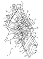
図1は、本発明の実施形態による車両のフロアパネル構造を備えた自動車のアンダボディを示す斜視図であり、図2は、フロントフロアパネルの拡大斜視図である。
図1に示すように、自動車のアンダボディ1は、車室の床部分(フロア部分)を構成するフロントフロアパネル2と、このフロントフロアパネル2の車体後方の一段高い位置に配設されリヤシート(図示せず)が配置されるセンタフロアパネル4と、さらに、このセンタフロアパネル4よりも車体後方の一段高い位置に配設され荷室の床部分を構成するリヤフロアパネル6とを備えている。
また、フロントフロアパネル2の車体前側の端縁部には、車室とエンジンルームを仕切るダッシュパネル8の下端縁部がスポット溶接等により接合されており、さらに、ダッシュパネル8の前方には、エンジンルームの左右両側を囲むように一対のフロントサイドフレーム10とフェンダエプロン12が設けられている。このフロントサイドフレーム10には、エンジン11が弾性体(図示せず)を介して着脱自在に取り付けられている。
【0015】
ダッシュパネル8の下側の部分である傾斜部8aには、車幅方向の補強部材であるNo.1クロスメンバ14が取り付けられている。このNo.1クロスメンバ14は、各フロントサイドフレーム10の車体外側に設けられそのフランジがフロントサイドフレーム10とダッシュパネル8の傾斜部8aに接合された閉断面構造である一対のトルクボックスメンバ16と、一対のフロントサイドフレーム10の中間に挟まるように配置され両端がフロントサイドフレーム10に接合されたダッシュロアクロスメンバ18とから構成されている。
このNo.1クロスメンバ14及び一対のフロントサイドフレーム10には、フロントサスペンションクロスメンバ15が取付けられ、このフロントサスペンションクロスメンバ15には、フロントサスペンション17が取り付けられている。
【0016】
図1及び図2に示すように、フロントフロアパネル2は、所定厚(例えば、厚さ0.65〜0.7mm)の鋼板を一体でプレス成形したもので、車幅方向のほぼ中央位置において上方に膨出するフロアトンネル部20が車体前後方向に延びている。また、フロアパネル2の車幅方向の両端側には、それぞれ、自動車のサイドボディ(図示せず)が取り付けられるようになっており、このサイドボディの下端縁部を閉断面構造のサイドシル21(仮想線で示す)が車体前後方向に延び、このサイドシル21に、スポット溶接等によりフロントフロアパネル2が接合されている。このサイドシル21の前方部は、No.1クロスメンバ14に接合されている。
【0017】
さらに、フロアトンネル部20と各サイドシル21との中間には、それぞれ車体前後方向に延びるように一対のフロアサイドフレーム22が設けられている。これらのフロアサイドフレーム22の前端は、上述したフロントサイドフレーム10の後端に接続され、後端は、リアサイドフレーム23に接続されている。これらのフロアサイドフレーム22は、断面コ字状の鋼板製部材をフロントフロアパネル2の底面に下方から重ね合わせて、略矩形の閉断面を構成している(図4参照)。この閉断面積を確保するために、フロントフロアパネル2には上方に突出する凸部24が形成され、この凸部24はこのフロントフロアパネル2の前縁部から車体前後方向の中央位置よりも後方の所定箇所まで前後方向に延びている。
さらに、リアサイドフレーム23には、リアサスペンションクロスメンバ25が取り付けられ、このリアサスペンションクロスメンバ25には、リアサスペンション27が取り付けられている。
【0018】
つまり、フロントフロアパネル2には、車体前後方向の補強構造として、左右両端側のサイドシル21に加えて、フロアトンネル部20とサイドシル21との間のほぼ中間にフロアサイドフレーム22及び凸部24が配設されており、これにより、自動車のボディの曲げ剛性やねじり剛性を十分に確保できるとともに、特に自動車の正面衝突時における車室の変形を最小限に抑えて、乗員を確実に保護することができるようになっている。
【0019】
さらに、車幅方向の補強構造としては、上述したNo.1クロスメンバ14に加えて、フロントフロアパネル2の車体前後方向のほぼ中央位置においてフロアトンネル部20を跨ぐようにして車幅方向に延びるNo.2クロスメンバ26と、フロアパネル2の後端縁部において車幅方向に延びるNo.3クロスメンバ28とが配設されている。No.2クロスメンバ26は、下向きに開放するコ字状断面の部材をフロアパネル2の上面に接合したもので、車幅方向の略中央部がフロアトンネル部20の形状に対応するように上方に屈曲している一方、左右両端部はそれぞれサイドシル21に接合されている。また、No.3クロスメンバ28は、下向きに開放するコ字状断面の部材をフロアパネル2の上面に接合したもので、その左右両端部は、それぞれ、サイドシル21に接合され、さらに、その一部がフロアサイドフレーム22に接合されている。
【0020】
以上の構成により、フロントフロアパネル(フロアパネル)2によって構成されるフロアは、各々車体前後方向に延びるフロアトンネル部20、フロアサイドフレーム22(凸部24を含む)及びサイドシル21、並びに、各々車幅方向に延びる各クロスメンバ14、26、28によって取り囲まれた略長方形状の若しくは長方形状に近い形状の8つのフロアパネルS1、S2、S3、S4から構成されている。そして、フロントサスペンション及びエンジンの振動は、フロアサイドフレーム22を経由してNo.1クロスメンバ14に伝わり、また、リアサスペンションから伝わる振動はフロアサイドフレーム22を経由してNo.3クロスメンバ28に伝わり、これらの振動が、さらに、サイドシル21を経由してNo.2クロスメンバ26に伝わり、これらのフロアサイドフレーム22、サイドシル21及び各クロスメンバ14、26、28の振動が、フロアパネルS1,S2,S3,S4に伝達される。
【0021】
本発明の実施形態は、後述するように、サイドシル21、フロアサイドフレーム22(凸部24を含む)、No.1クロスメンバ14、No.2クロスメンバ26及びNo.3クロスメンバ28からフロアパネルS1、S2、S3に伝達される振動をフロアパネルの一部分で大きく低減するようにしている。
以下、上述したサイドシル21、フロアサイドフレーム22(凸部24を含む)、No.1クロスメンバ14、No.2クロスメンバ26及びNo.3クロスメンバ28を総称してフレーム部材と呼ぶ。
【0022】
図2に示すように、第1フロアパネルS1は、一体成形されるフロントフロアパネル2の一部を構成し、フロアトンネル部20の左右両側においてそれぞれフレーム部材であるNo.1クロスメンバ14、サイドシル21、フロアサイドフレーム22(凸部24を含む)及びNo.2クロスメンバ26に溶接により接合されその周縁が拘束されている。
第2フロアパネルS2は、一体成形されるフロントフロアパネル2の一部を構成し、両側の第1フロアパネルS1の車体内方寄りに位置し、車体内方側の1辺はフロアトンネル部20と連続的に成形され、残りの3辺が、フレーム部材であるNo.1クロスメンバ14、フロアサイドフレーム22(凸部24を含む)及びNo.2クロスメンバ26に溶接により接合され、その3辺の周縁が拘束されている。
【0023】
第3フロアパネルS3は、一体成形されるフロントフロアパネル2の一部を構成し、第2フロアパネルS2の車体後方に位置し、車体内方側の1辺はフロアトンネル部20と連続的に成形され、残りの3辺が、フレーム部材であるフロアサイドフレーム22(凸部24を含む)、No.2クロスメンバ26及びNo.3クロスメンバ28に溶接により接合され、その3辺の周縁が拘束されている。
これらの第3フロアパネルS3の車体外方には、フロアサイドフレーム22からサイドシル21に亘る補強部材30が架設されている。
なお、図1に示すように、この補強部材30は、フロントシート32の取付座を兼用しており、フロントシート32の2つの前側の脚がNo.2クロスメンバ26に締結され、後側の一方の脚が補強部材30に締結され他方の脚がフロアトンネル部20に締結されるようになっている。
【0024】
第4フロアパネルS4は、一体成形されるフロントフロアパネル2の一部を構成し、第1フロアパネルS1の車体後方に位置し、フレーム部材であるサイドシル21、フロアサイドフレーム22(凸部24を含む)、No.2クロスメンバ26及びNo.3クロスメンバ28により囲まれた領域として区画されている。そして、この第4フロアパネルS4は、それらのフレーム部材21、22、26、28に溶接により接合されその周縁が拘束されている。
【0025】
次に、図2乃至図5により、本実施形態の車両のフロアパネル構造を具体的に説明する。
上述したように、エンジンやサスペンションからフレーム部材に伝達される振動は主に400Hz以下であり、本実施形態では、各フロアパネルS1、S2、S3に振動低減(遮断)構造を設けることにより、400Hz以下の広範囲の周波数帯の振動を低減させるようにしている。
【0026】
まず、図2及び図3により、フロアパネルS1、S2、S3に設けた振動低減構造を説明する。
先ず、第1フロアパネルS1は、上述したように、フレーム部材であるNo.1クロスメンバ14、サイドシル21、フロアサイドフレーム22及びNo.2クロスメンバ26の内方に形成された空間内に設けられ、これらのフレーム部材により囲まれた領域の中央部に車体上方に突出して高剛性部を形成する曲面部40と、この曲面部40の周囲の全域に平らな低剛性部を形成する平面部36を有し、この平面部36の外周端部は、これらのフレーム部材14、21、22、26と接合されている。
この曲面部40と平面部36との境界、即ち、曲面部40の外周縁は楕円形状になっている。そして、この曲面部40は、水平方向(車体の前後方向及び車幅方向)にその曲面高さが連続的に変化するドーム形状となっているので、平面部36に比べて上下方向及び水平方向に変形し難くなっている。
さらに、第1フロアパネルS1の平面部36の全域には、図3に示すように、制振材42が塗布されている。
【0027】
次に、第2フロアパネルS2は、上述したように、フレーム部材であるNo.1クロスメンバ14、フロアサイドフレーム22及びNo.2クロスメンバ26の内方に形成された空間に設けられ、これらのフレーム部材により囲まれた領域の中央部に車体上方に突出して高剛性部を形成する曲面部40と、この曲面部40の周囲の全域に平らな低剛性部を形成する平面部36を有し、この平面部36の外周端部は、各フレーム部材14、22、26と接合されている。
この曲面部40と平面部36との境界、即ち、曲面部40の外周縁は楕円形状になっている。そして、この曲面部40は、水平方向(車体の前後方向及び車幅方向)にその曲面高さが連続的に変化するドーム形状となっているので、平面部36に比べて上下方向及び水平方向に変形し難くなっている。
さらに、第2フロアパネルS2の平面部36の全域には、図3に示すフロアパネルS1と同様に、制振材42が塗布されている。
【0028】
さらに、本実施形態では、図2に示すように、第2フロアパネルS2の内方側縁の前方部分であるフロアトンネル部20との境界付近に、フロアトンネル部20の側面と第2フロアパネルS2とに跨るように車幅方向に延び且つ前後に離間した複数のビード44が設けられている。これらのビード44の車体外方側の端部の位置は、図2で二点鎖線で示すライン46上に並ぶように揃えられ、第2フロアパネルS2の後部におけるフロアトンネル部20の裾の位置を通っており、このようにして、平面部36の領域を規制するようにしている。
【0029】
さらに、第3フロアパネルS3は、フレーム部材であるフロアサイドフレーム22、No.2クロスメンバ26及びNo.3クロスメンバ28の内方に形成された空間に設けられ、これらのフレーム部材により囲まれた領域の中央部に車体上方に突出して高剛性部を形成する曲面部40と、この曲面部40の周囲の全域に平らな低剛性部を形成する平面部36と、を有し、この平面部36の外周端部は、各フレーム部材22、26、28と接合されている。
この曲面部40と平面部36との境界、即ち、曲面部40の外周縁は楕円形状になっている。そして、この曲面部40は、水平方向(車体の前後方向及び車幅方向)にその曲面高さが連続的に変化するドーム形状となっているので、平面部36に比べて上下方向及び水平方向に変形し難くなっている。
さらに、第3フロアパネルS3の平面部36の全域には、図3に示すフロアパネルS1と同様に、制振材42が塗布されている。
【0030】
この第3フロアパネルS3でも、第2フロアパネルS2と同様に、平面部36の領域を規制するために、図2に示すように、フロアトンネル部20に複数のビード44を設けている。第3フロアパネルS3においても、これらのビード44の車体外方側の端部の位置は、図2で二点鎖線で示すライン46上に並ぶように揃えられている。
ここで、第4フロアパネルS4は、その固有振動数が400Hz以上となるようにその剛性が調整されている。
【0031】
次に、図4及び図5により、本実施形態の振動低減構造を有するフロントフロアパネル2の断面構造を説明する。図4は、図2のA−A線に沿って見た第1フロアパネルS1と第2フロアパネルS2の車幅方向の断面図であり、図5は、図2のB−B線に沿って見た第2フロアパネルS2と第3フロアパネルS3の車両前後方向の断面図である。
【0032】
先ず、曲面部40と平面部36の形状について説明する。図4及び図5に示すように、各フロアパネルS1、S2、S3の曲面部40は、いずれも上方に突出しており、その断面形状は、曲率が連続して変化する曲面で構成されている。本実施形態では、この曲面部40は、断面がほぼ楕円形の球体の一部である立体形状に形成されている。一方、平面部36は曲率を有さないほぼ平らに構成されている。
曲面部40は、平面部36との境界部aから所定の角度で立ち上がるようになっている。言い換えると、その境界部aは、鋭角的に折れ曲がるように、即ち、境界部aを境に平面部36と曲面部40のそれぞれの曲率又は法線方向が、不連続となっている。ここで、所定の角度は、曲面部40の剛性がより高まるように、その曲面の形状、大きさ、高さ等によって定められる。
【0033】
次に、各フロアパネルS1、S2、S3と各フレーム部材の接続部分の構造について説明する。
図4に示すように、第1フロアパネルS1の平面部36の車体外方縁は、サイドシル21の側面に溶接により接合されている。
また、第1フロアパネルS1と第2フロアパネルS2の間には、曲面部40及び平面部36を構成するパネル(フロントフロアパネル2)と一体で成形された凸部24が設けられ、この凸部24は、フロアサイドフレーム22に溶接により接合されている。
さらに、第2フロアパネルS2の車体内方には、フロアトンネル部20が連続的に成形されている。このフロアトンネル部20には、上述したように、第2フロアパネルS2の車体内方側の平面部36の領域を規制するための複数のビード44が設けられている。
【0034】
次に、図5に示すように、第2フロアパネルS2の平面部36の前縁は、No.1クロスメンバ14の側面に溶接により接合されている。また、第1フロアパネルS1の平面部36の前縁も、図5に示す第2フロアパネルS2と同様にNo.1クロスメンバ14の側面に溶接により接合されている。
また、第2フロアパネルS2と第3フロアパネルS3の間のフロントフロアパネル2の上方に、No.2クロスメンバ26が溶接により接合されている。
図示しないが、第1フロアパネルS1と第4フロアパネルS4の間も、それらの間のフロントフロアパネル2の上方に、No.2クロスメンバ26が溶接により接合されている。
第3フロアパネルS3の車体後方側では、フロントフロアパネル2の車両後方端部に、その上方に、No.3クロスメンバ28が溶接により接合されている。
【0035】
次に、図3、図4及び図5により、各フロアパネルの制振材42の配置について詳細に説明する。
上述したように、制振材42は、各フロアパネルの平面部36の全域に塗布されている。具体的には、以下の通りである。
先ず、図4及び図5に示すように、第1フロアパネルS1においては、平面部36の2辺の外周端部は、フレーム部材であるNo.1クロスメンバ14及びサイドシル21の側面に溶接により接合され、残りの2辺の外周端部は、フロアサイドフレーム22及びNo.2クロスメンバ26に溶接により接合されている。また、第1フロアパネルS1の平面部36の内周端部は、曲面部40の立上り部40aと当接している。このため、平面部36は、フレーム部材14、21、22(凸部24を含む)、26と曲面部40の立上り部40aとにより、溝形状を形成し、この溝形状を形成する平面部36の全域に、後述するように、制振材42が塗布されるようになっている。ここで、制振材42は、フレーム部材14、21、22(凸部24を含む)、26の側面、平面部36、及び、曲面部40の立上り部40aに接着されている。
【0036】
また、第2フロアパネルS2も、同様に、平面部36は、フレーム部材14、22(凸部24を含む)、26及びフロアトンネル部20の立上がり部20aと曲面部40の立上り部40aとにより、溝形状を形成し、この溝形状を形成する平面部36の全域に、後述するように、制振材42が塗布されるようになっている。ここで、制振材42は、フレーム部材14、22(凸部24を含む)、26の側面又はフロアトンネル部20の立上がり部20a、平面部36、及び、曲面部40の立上り部40aに接着されている。
【0037】
さらに、第3フロアパネルS3も、同様に、平面部36は、フレーム部材22(凸部24を含む)、26、28及びフロアトンネル部20の立上がり部20aと曲面部40の立上り部40aとにより、溝形状を形成し、この溝形状を形成する平面部36の全域に、後述するように、制振材42が塗布されるようになっている。ここで、制振材42は、フレーム部材22(凸部24を含む)、26、28の側面又はフロアトンネル部20の立上がり部20a、平面部36、及び、曲面部40の立上り部40aに接着されている。
なお、上述した実施形態では、第1フロアパネル乃至第4フロアパネルS4を1枚のパネルをプレス成形することにより形成したものであるが、本発明は、これに限らない。例えば、第1フロアパネルS1を単独でプレス成形し、残りの第2フロアパネルS2、第3フロアパネルS3及び第4フロアパネルS4を1枚のパネルをプレス成形するようにしても良い。
【0038】
次に、本実施形態のフロアパネル構造の作用効果について説明する。
本実施形態では、各フロアパネルS1、S2、S3において、曲面部(高剛性部)40より剛性の低い平面部(低剛性部)36を設け、フレーム部材からフロアパネルに伝わる振動が平面部(低剛性部)36で大きく振動するようにすると共に、この平面部36に制振材42を集中して配置して振動を大きく減衰させるようにしている。
つまり、フレーム部材は、車体上下方向、水平方向(車幅方向又は車体前後方向)及びフレーム部材の軸線周りの回転を含む様々な方向の振動を伴い、この振動を受けた平面部36は、フレーム部材に比べて剛性が低いことから大きく振動する。一方、曲面部40は、その湾曲した形状により平面部36に比べて大きくその剛性が高められ、振動しにくくなっている。
【0039】
さらに、各フロアパネルS1、S2、S3には、曲面部40と平面部36との剛性差により、平面部36が振動遮断部として形成されている。即ち、フレーム部材から高剛性部(曲面部40)へ伝達される振動は、この平面部36で遮断、即ち、振動の伝達量が低減されるようにしている。
このような振動遮断(低減)効果は、低剛性部と高剛性部との間の剛性が変化する境界部で振動の反射が生じて、フレーム部材からパネル部に伝わる振動が、反射した分だけ遮断(低減)されることや、振動し易い平面部36(低剛性部)に囲まれた曲面部40(高剛性部)がその湾曲した形状によって、それが一体として、その自身の重量による慣性力によりその場に留まろうとすることで、パネル部より剛性の小さい平面部36(低剛性部)が、ばねのように働いて振動を受け止め、フレーム部材から曲面部40に振動が遮断されることで生じる。
また、振動遮断効果は、低剛性部である平面部36に制振材42が設けられることで、平面部36で振動が大きく減衰されることから、より大きく発揮される。
【0040】
次に、図6により、このようなフロアパネルの構造上の特性を説明する。
図6(A)は、代表例として、第1フロアパネルS1の車幅方向の断面構造を模式的に示した断面図であり、図6(B)は、このフロアパネルの各部の剛性の違いを、定性的に表したものである。
図6(B)に示すように、平面部36と曲面部40とは剛性差があり、この剛性差が大きい程、平面部36は曲面部40に比べて振動し易く、さらに、平面部36に制振材42を設けることで、制振効果及び振動遮断効果が大きく発揮される。また、平面部36と曲面部40との境界部を境に剛性が不連続であることで、平面部36と曲面部40との振動の大きさの差を顕著に発生させ、制振材42の効果を大きく発揮させることができる。
【0041】
次に、図6(C)に、本実施形態によるフロアパネルに生じる歪みエネルギー分布を、従来の全面がフラットなフロアパネルの歪みエネルギー部分と共に示す。図6(C)は、本実施形態によるフロアパネル及び従来のフロアパネルをFEM解析モデルに置き換えて解析した結果である。
図6(C)に示すように、従来のフロアパネルでは、パネル面全体に亘って歪みエネルギーが分布している。即ち、従来のフロアパネルでは、その剛性が全面にわたり一定であり、フレーム部材の振動により、その全面で大きな曲げ振動が生じやすい。
一方、本実施形態によるフロアパネルでは、平面部36に生じる歪みエネルギーが曲面部40の歪みエネルギーに比べて非常に大きくなっている。このように、平面部36に振動エネルギーが集中するのは、上述したように、平面部36が曲面部40に比べて剛性が低く振動し易くなっているからであり、一方、このように振動エネルギーが集中している平面部36に制振材42を設けることで、フレーム部材からフロアパネルに伝達される振動を大きく減衰させ且つ曲面部40に伝達される振動を遮断(低減)することができる。
【0042】
次に、本実施形態によるプロアパネルの制振材の振動低減(遮断)特性を説明する。
本実施形態による振動減衰効果を確認するために、図7に示す、パネルA、パネルB及びパネルCを作成し、これらの各パネルを図1及び図2に示す第1フロアパネルS1及び第2フロアパネルS2の領域に配置し、アンダーボディのサスペンションクロスメンバに取付けられたダブルウィッシュボーンサスペンションのロアアームに、400Hz以下の周波数帯域(ホワイトノイズ)の加振力Fを加振器で与えて、各パネル面の音響放射パワーPを測定した。ここで、パネルAは、従来の全面がフラットなパネル37で全面に制振材42が貼り付けられおり、パネルBは、平面部36及び曲面部40の全面に制振材42を貼付けたパネルであり、パネルCは、本実施形態のパネルであり、平面部36のみに制振材42が貼り付けられている。
【0043】
図8は、この実験により得られた、制振材の重量と音響放射パワーとの関係を示す線図である。
図8から明らかなように、音響放射パワーを、例えば、音響放射パワーPaまで下げるために必要な制振材重量は、制振材を全面に貼付けた従来のパネルAで約5.8kgであるのに対し、本実施形態の制振材を平面部のみに貼り付けたパネルCで約1.4kgとなり、同じ音響放射パワーまで下げるために必要な制振材重量が約4分の1に低減している。パネルCでは、制振材を、大きく振動している平面部(低剛性部)にのみ配置すると共に上述した低剛性部の振動遮断構造により、音響放射パワーを大幅に低減することができるのである。
また、制振材重量が0kgの場合において、従来のパネルAに対し、平面部36及び曲面部40を有するフロアパネル(パネルB及びC)は、音響放射パワーが低減している。これは、上述したように、パネルの低剛性部(平面部)と高剛性部(曲面部)の剛性差による振動遮断効果によるものである。
【0044】
さらに、平面部36及び曲面部40の全面に制振材42を貼付けたパネルBにおいては、音響放射パワーPaまで下げるために必要な制振材重量は約2kgとなり、従来のパネルAに対し、同じ音響放射パワーまで下げるために必要な制振材重量が約3分の1に低減する。
【0045】
さらに、図8から明らかであるが、同じ重量の制振材を用いた場合の各パネルから生じる音響放射パワーは、例えば、制振材重量を2kgとすると、従来のパネルAでは約80dB程度であるのに対し、本実施形態の平面部にのみ制振材を設けたパネルCでは、約76dB、平面部36及び曲面部40の全面に制振材42を貼付けたパネルBでは77dBと、同じ重量の制振材を設けた場合に、より大きな振動減衰効果が得られる。
【0046】
以上説明したように、本実施形態のフロアパネル(パネルC)によれば、少量の制振材で従来と同様の振動減衰効果が得ることができ、制振材の使用量を大幅に低減して、車体の軽量化、コスト低減を図ることができる。反対に同量の制振材でより大きな振動減衰効果を得ることも可能となる。
【0047】
以上説明したように、平面部36に制振材42を設けた場合に制振効果が大きく発揮されることから、フロアパネルの全面に制振材を配置するよりも、平面部36のみに制振材を配置することにより、より少ない重量の制振材でその振動減衰効果が大きく発揮され、フロアパネルの振動を低減することができる。
さらに、平面部により多くの重量の制振材を設け、曲面部は相対的に少ない量の制振材を配置するようにしても良い。この場合、平面部36に制振性能即ち減衰力が大きい制振材42を配置し、曲面部40に、制振性能の小さい又はその厚さが薄い制振材43を貼り付けるようにしても良い。
【0048】
一方、フレーム部材を介して伝わるエンジンやサスペンションの振動の他に、フロアパネルを直接振動させるようないわゆる透過音による音響放射が問題となる場合がある。この音響放射を防止するために、図9に示すように、平面部36に、制振性能即ち減衰力が大きい制振材42を配置し、曲面部40に、透過音による騒音を防止するために、吸音材43を貼り付けるようにすると効果的である。
【0049】
次に、図10により、平面部36に配置された制振材42の変形状態の一例を説明する。図10は、代表例として、平面部36及び制振材42のうち、第1フロアパネルS1の車体外方側の平面部36及び制振材42を拡大して示した部分拡大図である。
図10において、実線は、平面部36、曲面部40、及び、制振材42の静止状態を示し、破線は、これらの変形状態を示している。
上述したように、制振材42は、フレーム部材14、21、22(凸部24を含む)、26、28又はフロアトンネル部20の立上がり部20a、平面部36、及び、曲面部40の立上り部40aに接着されており、この例では、制振材42は、平面部36の曲げ変形により大きく湾曲すると共に、フレームに接着された部分42aと曲面部40の立上り部に接着された部分42bとの間の相対変位によって変形している。このような変形状態では、制振材42は、せん断変形を受けると共に、フレームに接する部分42aと曲面部40の立上り部に当接する部分42bの間で圧縮膨張変形を受ける。例えば、制振材42は、破線P1の状態と破線P2の状態との間で振動する間、フレームに接着された部分42aと曲面部40の立上り部に接着された部分42bとの間の相対変位で膨張及び圧縮を繰り返し、さらに、フレームに接着された部分42aと、平面部36と、曲面部40の裾に接着された部分42bとの間でせん断変形を受ける。
このように、制振材42は、パネルに貼付けたシート状の制振材がパネルの曲げ振動による伸縮によってのみ歪む従来のフロアパネル構造と比べて、より大きく歪み且つその変形状態が複雑であることから、その制振効果及び減衰効果は非常に大きいものとなる。
【0050】
本実施形態では、曲面部40は各フロアパネルS1、S2、S3にそれぞれ各1つ設けられている。このように曲面部をフロアパネルに1つ設けることで、曲面部を複数設ける場合より平面部の形状がより単純になり振動し易くなる。
一方、曲面部を複数設けると、ある特定の振動モードが生じやすくなり、フロアパネルからの音響放射が大きくなることがあるが、第2実施形態として後述するように、フロアパネルに特定の周波数で特定の振動モードを生じさせるように、積極的に2つ又はそれ以上の曲面部を設けて、後述する振動モード調整構造を兼ねるようにすることも出来る。
なお、第1実施形態において、各曲面部40を下方に突出するようにしても良い。
【0051】
さらに、本実施形態では、曲面部40の剛性を高めるために、その平面部36との境界部、即ち、曲面部40の外周縁を楕円形にしている。
ここで、曲面部40の剛性を高めるには、曲面部40の深さ(高さ)を大きくすれば良いが、この曲面部40を上方に突出させる場合には、車室内のフロアを平坦にするために、フロントフロアパネル2に敷くフロアマット等の形状や配置を工夫するなどの対策が必要となり、曲面部40の車室内への突出高さがあまりに大きいとフロアマットの設置が困難になることや、フロアの踏み心地感を悪化させることとなる。一方、曲面部40を下方に突出させる場合には、フロア下部に設けられている燃料タンク、排気管、触媒等に干渉することになり、曲面部40の高さはあまり大きくすることができない。
ここで、曲面部40の高さを一定に抑えつつ、その剛性を高めるには、曲面部の外周縁の形状を、円形や楕円形にするのが良い。
【0052】
以上説明したように、本実施形態のフロアパネルでは、従来に比べて、少量の制振材で従来と同様の振動減衰効果が得られることから、車体の軽量化、コスト低減を図ることもできる。反対に同量の制振材でより大きな振動減衰効果を得ることも可能となる。また、本実施形態の車両のフロアパネル構造に設けた振動低減(遮断)構造によれば、400Hz以下の広範囲の周波数帯の振動を低減し、各フロアパネルS1、S2、S3からの音響放射を低減することができる。
【0053】
次に図11及び図12により本発明の車両のフロアパネル構造の第2実施形態を説明する。
上述したように、本実施形態の車体のフロアパネル構造は、振動低減(遮断)構造として、曲面部40と平面部36とを設け、この平面部36に制振材42を設けることにより、従来より少量の制振材で、400Hz以下の広い周波数帯域において振動による騒音を低減できるものである。
また、上述したように、フレーム部材を伝わってくる振動として、エンジン自体の振動や、サスペンションから伝わるロードノイズが問題となる。このうち、ロードノイズには、一般に、タイヤの空洞共鳴によるものと、サスペンションの共振によるものとがあり、一般的には、タイヤの空洞共鳴によるロードノイズのピークは200〜300Hzの範囲の周波数帯域に現れ、サスペンションの共振によるロードノイズのピークは200Hz以下の帯域に現れる。このうち、特に、タイヤの空洞共鳴によるロードノイズが問題となることが多い。
【0054】
このため、第2実施形態の車体のフロアパネル構造では、上述した振動低減(遮断)構造が、さらに、振動モード調整構造(振動モード調整部)を兼ねるようにし、タイヤの空洞共鳴による振動による音響放射をさらに低減させるようにしている。
第2実施形態の車体のフロアパネル構造における振動モード調整構造(振動モード調整部)は、特定の周波数、例えば、本実施形態では250Hz付近の周波数で、フロアパネルを音響放射効率の低い振動モードで振動させるようにしたものである。
【0055】
ここで、音響放射効率の低い振動モードについては、上述した特許文献1(特開平9−202269号公報)に説明されている。要するに、矩形状の領域の縦横にそれぞれ励起される定在波の腹の数をそれぞれn,mとしたときに、一例として図11に示すように、「n×m=偶数」であれば、当該パネル内で隣接する逆相の部分からの放射音が互いに打ち消し合って、音響放射エネルギが大幅に低下することになる。
【0056】
すなわち、図11Aに示す「2×1=2」の振動モードでは、フロアパネル内の2つの部分が逆位相かつ同振幅で振動し、放射音同士が打ち消し合うことになり、このときに音響放射効率が最小となる。
また、この2×1モードの振動を起こすためにはフロアパネルの振動領域を、特に横辺と縦辺との比が略1:2である長方形状に形成することが好ましい。
【0057】
この第2実施形態においては、第1フロアパネルS1は、図12に示すように、その外周縁がほぼ円形の2つの曲面部40が車体前後方向に並んで形成され、その残りの部分に平面部36が形成されている。これらの曲面部40は、それぞれ第1フロアパネルS1の前部及び後部をほぼ円形の凸曲面状に上方へ突出させて形成されている。また、平面部36には、第1実施形態と同様に、制振材42が平面部36の全域に塗布されている。
また、この第1フロアパネルS1は、その車両前後方向の長さと車幅方向の長さが、ほぼ2×1の長さの長方形状になっている。
このように、曲面部40を車体前後方向に2つ設け、また、パネルS1をほぼ2×1の長方形状に形成することで、上記2×1の振動モードを発生し易くしている。
【0058】
第2フロアパネルS2も、第1フロアパネルS1と同様に、2つの曲面部40及び平面部36が形成され、この平面部36の全域に制振材42が塗布されている。
また、第2フロアパネルS2は、その車体内方側のフロアトンネル部20の立ち上り部が変化するため、第1フロアパネルS1とは異なり、前方の幅が後方の幅よりも広い非長方形状に形成されている。そこで、このフロアパネルS2には、第2フロアパネルS2の領域を規制する複数のビード44が設けられ、その複数のビード44の車体外方の端及びこれらのビード44の後方のフロアトンネル部20の裾を通って車体前後方向に延びるライン46と対向するフロアサイドフレーム22との間隔、即ち、第2フロアパネルS2の車幅方向の寸法が車体前後方向の全長に亘って略一定となるようにしている。また、このビード部44は、平面部36の領域をも規制している。
この結果、第2フロアパネルS2においては、第2フロアパネルS2を3方から囲む各フレーム部材14、22、26とライン46とにより囲まれた領域の車両進行方向の長さと車幅方向の長さが、ほぼ2×1の長さの長方形状となる。
【0059】
第3フロアパネルS3も、第1フロアパネルS1と同様に、2つの曲面部40及び平面部36が形成され、この平面部36の全域に制振材42が塗布されている。
また、第2フロアパネルS3も、第2フロアパネルS2と同様に、複数のビード44が設けられ、第3フロアパネルS3を3方から囲む各フレーム部材22、26、28とライン46とにより囲まれた領域の車両進行方向の長さと車幅方向の長さが、ほぼ2×1の長さの長方形状になっている。
なお、第2実施形態において、各曲面部40を下方に突出するようにしてもよい。
【0060】
この第2実施形態においては、各フロアパネルS1、S2、S3において、2×1モードの振動が特定の周波数(250Hz)で生じるように、それぞれの曲面部40の形状や深さ等、及びフロアパネルの板厚等を調整している。つまり、曲面部40を成形する前のフロアパネルの2×1モードの共振周波数が250Hzを下回るようにし、曲面部40を成形することによりフロアパネルの2×1モードの共振周波数を上げて、250Hzとなるようにしている。なお、各曲面部40に、剛性の調整と滑り止めとを兼ねたほぼ十字状又は放射状の凹凸ラインを形成しても良い。
【0061】
この第2実施形態では、これらの曲面部40の形状及び深さを適宜、変更することで、上述した所定周波数帯域つまり250Hz付近の周波数の振動入力に対して確実に2×1モードの振動を励起させることができ、これにより、各フロアパネルにおいて相隣る逆位相の部分からの放射音を互いに打ち消し合わせて(放射音のキャンセレーション)、音響放射効率を極めて低くすることができる。
【0062】
以上説明したように、第2実施形態では、上述したフロアパネルS1〜S3は、高剛性部として構成された曲面部40、低剛性部として構成された平面部36及び、この平面部36に設けられた制振材42によって、主に400Hz以下の振動を従来より少量の制振材で減衰させると共に、平面部36により、フレーム部材から曲面部40に伝達される主に400Hz以下の周波数領域の振動を遮断し、さらに、曲面部40及び平面部36で構成された振動モード調整構造により、所定周波数帯域(200Hz〜300Hz)の振動入力、特にほぼ250Hzの振動入力に対して音響放射効率の低い2×1の振動モードが励起されるようにしている。
従って、この第2実施形態による車両のフロアパネル構造によれば、振動モード調整構造(振動モード調整部)を兼ねた、曲面部40、平面部36及び、この平面部36に設けられた制振材42により、振動を低減させ且つ音響放射を低減させることができる。
【0063】
ここで、上述した第1実施形態及び第2実施形態において、曲面部40及び平面部36の形状や大きさ、例えば、曲面部の深さや形状(曲率の分布等)は、その車両自体に固有の実際にフレーム部材を介して伝達されてくる振動の大きさや周波数ピーク、フロアパネルの板厚や形状・寸法、その他車両の構造上の制約等を考慮して定められる。この場合、それらの深さは、低剛性部である平面部36の剛性がより低く、振動エネルギーがより集中するように、また、振動遮断効果がより大きく発揮されるようにする。
【0064】
次に、図13により、上述した第1及び第2実施形態における平面部36に制振材を塗布するための方法を説明する。
図13に示すように、平面部36及び曲面部40をプレスで成形しフレーム部材に溶接した後、注入用ガン50で、液状ゴム等の液状物質である制振材42を平面部36の全域に塗布する。例えば、制振材42は、第1実施形態における第1フロアパネルS1の車体外方側の平面部36では、サイドシルの側面21aと、平面部36と、上方に突出した曲面部40の立上り部分40aとで形成された溝状の部分に流し込むことで設定される。上述した第1及び第2実施形態では、平面部36がフレーム部材の側面に連結され曲面部40が上方に突出して設けられているので、フレーム部材の側面21a、平面部36及び曲面部40の立上り部40aにより溝形状が形成され、液状の制振材を容易に塗布することができるようになっている。
【0065】
ここで、制振材42は、注入用ガン50で注入できる制振機能を持つ液状物質であれば、液状ゴムに限らない。制振材の注入の際には、例えば、注入用ガン50から連続して一定量の液状物質を吐出させつつ、注入用ガン50を平面部36の全周に沿って移動させ、一周させればよい。
ここで、制振材として、日本特殊塗料株式会社のW‐250、米国EFTEC社のEF3000及び3300等を使用することができる。
なお、平面部36に溝形状を形成しない場合、例えば、平面部36がフレーム部材の上面と同じ高さに設定された場合や、曲面部40を下方に突出させた場合には、発泡ゴムを平面部36に貼り付け、その後、塗装の乾燥工程において、発泡ゴムを発泡させて設定するようにしても良い。
【0066】
【発明の効果】
以上説明したように、本発明によれば、騒音を低減するための制振材の使用量を低減して車両の軽量化を図ることができる。また、車体のフレーム部材からフロアパネルへ伝わる振動の伝達量そのものを低減して車室内の騒音を低減するができる。
【図面の簡単な説明】
【図1】本発明の第1実施形態による車両のフロアパネル構造を備えた自動車のアンダボディを示す斜視図である。
【図2】本発明の車体のフロアパネル構造の第1実施形態を示す斜視図である。
【図3】第1実施形態の第1フロアパネルを拡大して示す部分拡大斜視図である。
【図4】図2のA‐A線に沿って見たフロアパネルの車幅方向の断面構造を示す断面図である。
【図5】図2のB‐B線に沿って見たフロアパネルの車体前後方向の断面構造を示す断面図である。
【図6】第1実施形態によるフロアパネルを模式的に示した断面図、剛性を示す線図及び歪みエネルギー分布を示す線図である。
【図7】本発明の第1実施形態による振動低減特性を説明するための従来の全面がフラットなフロアパネルと曲面部及び平面部の全面に制振材を貼付けたフロアパネルと第1実施形態のフロアパネルとを模式的に示した断面図である。
【図8】本発明の第1実施形態による振動低減特性を示す線図である。
【図9】図6のフロアパネルにさらに吸音材を設けたフロアパネルを模式的に示した断面図である。
【図10】第1実施形態による振動低減構造(振動遮断構造)の平面部及び制振材を拡大した示す部分拡大図である。
【図11】本発明の第2実施形態による振動モード調整構造のフロアパネルの放射音の相殺(キャンセレーション)を示す概念図である。
【図12】本発明の車体のフロアパネル構造の第2実施形態を示す斜視図である。
【図13】第1及び第2実施形態における制振材設定方法を説明するためのフロアパネルの部分拡大断面図である。
【符号の説明】
S1 第1フロアパネル
S2 第2フロアパネル
S3 第3フロアパネル
S4 第4フロアパネル
1 自動車のアンダボディ
2 フロントフロアパネル
10 フロントサイドフレーム
11 エンジン
14 No.1クロスメンバ
17 フロントサスペンション
20 フロアトンネル部
21 サイドシル
22 フロアサイドフレーム
23 リアサイドフレーム
24 凸部
26 No.2クロスメンバ
27 リアサスペンション
28 No.3クロスメンバ
36 平面部
40 曲面部
42 制振材
44 ビード[0001]
BACKGROUND OF THE INVENTION
The present invention relates to a floor panel structure of a vehicle body, and in particular, an automobile floor is constituted by a floor panel that is connected to a plurality of frame members that are arranged in a vehicle longitudinal direction and a vehicle width direction and are connected to an engine or a suspension. It relates to the floor panel structure of the vehicle body.
[0002]
[Prior art]
Vibration from the frame member to which the engine and suspension are connected is transmitted to the floor panel, and this floor panel vibrates. As a result, unpleasant vehicle interior vibration and noise are generated by greatly vibrating the air in the vehicle interior. It is known. In this case, vibrations of the engine itself and road noise transmitted from the suspension become a problem as the vibration source. This road noise is generally caused by tire cavity resonance and suspension resonance.
Conventionally, in order to suppress these vibration noises, damping materials and vibration-proofing materials are generally pasted as various vibration-proofing and sound-proofing measures on each part of the floor panel and the vehicle body in the vicinity thereof. . This can reduce vibration and noise, but on the other hand, it requires a very large amount of damping material and anti-vibration material, which increases the weight of the vehicle, thereby causing various adverse effects and costs. There was a big problem.
[0003]
Furthermore, unpleasant vibrations transmitted from the engine and suspension are mainly 400 Hz or less in automobiles, and particularly have a peak at a frequency around 250 Hz, which is road noise caused by tire cavity resonance. It is also known to increase the rigidity by forming a large number of beads or increasing the panel thickness, thereby shifting the natural frequency of the floor panel to a high band higher than 400 Hz. That is, the floor panel does not resonate at the resonance frequency of the suspension, the cavity resonance frequency band of the tire, or the like, thereby reducing unpleasant vibration noise.
In this case, there is an advantage that the resonance peak in the low frequency region can be suppressed, but on the other hand, the vibration in the high frequency region increases on the other hand. In the same manner as described above, the weight of the vehicle increases, and as a result, there are various adverse effects and costs, and it has been desired to solve this problem.
[0004]
Therefore, the present applicant pays attention to the relationship between the vibration frequency of the vibration transmitted to the floor panel and the vibration mode, and proposes a floor panel structure in which the vibration mode has a smaller acoustic radiation level at a specific vibration frequency (resonance region). (Patent Document 1). In other words, this floor panel structure has a vibration mode of 2 × in the frequency range near 250 Hz, which is road noise caused by tire cavity resonance transmitted to the floor panel as the most unpleasant vibration as a specific frequency. The rigidity of the floor panel is partially adjusted so that an even number of vibration antinodes are generated as in the 2 mode or 2 × 1 mode so that the sound waves emitted from the antinodes cancel each other out. By setting it, the sound radiation level is lowered to reduce the noise in the passenger compartment.
[0005]
[Patent Document 1]
JP-A-9-202269
[0006]
[Problems to be solved by the invention]
However, the above-described method of attaching a vibration damping material or a vibration damping material to the entire surface of the floor panel causes problems that the material cost increases and the weight of the vehicle body increases due to the heavy use of the vibration damping material. In addition, when the panel thickness is increased, the vehicle weight increases.
Further, the floor panel structure described in
[0007]
Here, the present inventors show that the greater the deformation of the damping material, the higher the vibration damping effect, and the vibrations from the engine and suspension, which are the main factors of unpleasant vehicle interior vibration and noise, Focusing on the fact that it is transmitted to the floor panel via the members, an attempt was made to solve the above-mentioned problems of the prior art.
The present invention has been made in order to solve the above-described problems of the prior art, and the vibration of the floor panel caused by the vibration transmitted from the frame member of the vehicle body to the floor panel is reduced with a damping material having a weight smaller than that of the conventional one. An object of the present invention is to provide a vehicle body floor panel structure capable of greatly reducing vibrations, reducing noise in the passenger compartment, and reducing the weight of the vehicle.
[0008]
[Means for Solving the Problems]
In order to achieve the above object, the present invention provides a vehicle body that forms a floor of an automobile by floor panels that are arranged in a vehicle body longitudinal direction and a vehicle width direction and are connected to a plurality of frame members that are connected to an engine or a suspension. The floor panel has a curved surface portion that protrudes upward or downward at a central portion of a region surrounded by a plurality of frame members of the floor panel to form a highly rigid portion, and the curved surface portion. All around Lower rigidity than high rigidity part A flat portion that forms a flat low-rigidity portion, and only on the flat portion of the floor panel To attenuate the vibration of the plane It is characterized by a damping material.
In the present invention configured as above, a curved surface portion that protrudes upward or downward at the center portion of the area surrounded by the plurality of frame members of the floor panel to form a highly rigid portion, and the periphery of the curved surface portion And a flat surface portion that forms a flat low-rigidity portion over the entire area, so that vibration is reflected at the boundary where the rigidity changes due to a difference in rigidity between the curved surface portion and the flat surface portion, or a flat surface portion with low rigidity. Since the vibration is greatly received and the vibration is received, vibration in a wide frequency range, for example, 400 Hz or less transmitted from the frame member to the floor panel is reduced.
Furthermore, on the flat part of the floor panel To damp that vibration Since the damping material is provided, the vibration is further reduced at the plane portion that vibrates greatly. Also, Vibrating greatly Since the vibration damping material is provided only on the flat part of the floor panel, the vibration of the floor panel can be greatly reduced with a small weight of the vibration damping material. Since the damping effect can be obtained, the weight of the vehicle body can be reduced and the cost can be reduced, and the noise in the passenger compartment can be further reduced.
[0009]
In order to achieve the above-mentioned object, the present invention comprises a floor of an automobile by floor panels connected to a plurality of frame members arranged in the vehicle longitudinal direction and the vehicle width direction and connected to an engine or suspension. A floor panel structure of a vehicle body, wherein the floor panel protrudes upward or downward at a central portion of an area surrounded by a plurality of frame members of the floor panel, and forms a high rigidity portion. Around the entire area around the curved surface Lower rigidity than high rigidity part A flat portion that forms a flat low-rigidity portion, and the flat portion and the curved portion of the floor panel To damp those vibrations A damping material is provided, and the damping material is characterized in that a larger amount is provided in the flat portion than in the curved portion.
In the present invention configured as above, a curved surface portion that protrudes upward or downward at the center portion of the area surrounded by the plurality of frame members of the floor panel to form a highly rigid portion, and the periphery of the curved surface portion All over Lower rigidity than high rigidity part And a flat surface portion that forms a flat low-rigidity portion, so that vibration is reflected at the boundary where the rigidity changes due to a difference in rigidity between the curved surface portion and the flat surface portion, or a flat surface portion with low rigidity. Since the vibration is greatly received and the vibration is received, vibration in a wide frequency range, for example, 400 Hz or less transmitted from the frame member to the floor panel is reduced.
Furthermore, on the flat part of the floor panel To damp that vibration Since the damping material is provided, the vibration is further reduced at the plane portion that vibrates greatly.
Moreover, the damping material is Vibrating greatly Since a large amount is provided in the flat part, the vibration of the floor panel can be greatly reduced with a damping material with a small weight, and a vibration damping effect equivalent to or higher than that of the conventional one can be obtained with a smaller amount of damping material. Therefore, the weight of the vehicle body can be reduced and the cost can be reduced, and the noise in the passenger compartment can be further reduced.
[0010]
In the present invention, it is preferable that the curved surface portion of the floor panel is formed in a substantially circular or substantially elliptical boundary edge with the flat surface portion.
According to the present invention configured as described above, it is possible to effectively increase the rigidity of the curved surface portion while keeping the height of the curved surface portion low. As a result, the protruding height into the passenger compartment can be suppressed, making it easy to install a floor mat or the like in the passenger compartment. The vibration of the floor panel can be greatly reduced while preventing interference.
In the present invention, preferably, one curved surface portion of the floor panel is provided in a region surrounded by a plurality of frame members.
According to the present invention configured as described above, the planar portion is likely to vibrate, and the vibration of the floor panel can be greatly reduced more effectively.
[0011]
In the present invention, it is preferable that the curved surface portion and the flat surface portion of the floor panel are configured as a vibration mode adjusting portion in which a region surrounded by a plurality of frame members vibrates in a 2 × 1 mode at a specific frequency.
In the present invention configured as described above, the curved surface portion and the flat surface portion of the floor panel are configured as a vibration mode adjusting portion in which a region surrounded by a plurality of frame members vibrates in a 2 × 1 mode at a specific frequency. Therefore, it is possible to greatly reduce the acoustic radiation due to the vibration of a specific frequency.
Furthermore, according to the present invention, as described above, the vibration mode adjusting portion is configured by the curved surface portion and the flat surface portion, and the vibration damping material is provided only on the flat surface portion, whereby the vibration is transmitted from the frame member to the floor panel. Acoustic radiation due to vibrations in a wide frequency range, for example, 400 Hz or less can also be reduced. Therefore, according to the present invention, it is possible to reduce the weight of the vehicle and reduce the cost, and at the same time, it is possible to reduce noise at a specific frequency by the vibration mode adjusting unit and simultaneously reduce vibrations other than the specific frequency. . Furthermore, even when the vibration mode adjustment unit is provided, it is not necessary to attach a damping material to the entire surface of the floor panel, and an increase in the weight of the vehicle body can be prevented.
[0012]
In the present invention, it is preferable that the specific frequency is a cavity resonance frequency of the tire.
In the present invention configured as described above, acoustic radiation due to vibration caused by tire cavity resonance can be greatly reduced.
In the present invention, the specific frequency is preferably about 250 Hz.
In the present invention configured as described above, acoustic radiation due to vibration of about 250 Hz can be greatly reduced.
[0013]
In the present invention, it is preferable that the flat portion of the floor panel is connected to the frame member or provided integrally with the floor tunnel portion, and the curved surface portion is provided so as to protrude upward, and the side surface or floor of the frame member is provided. A groove shape is formed by the rising portion of the tunnel portion, the flat portion, and the rising portion of the curved surface portion, and the vibration damping material is applied in the groove shape.
According to the present invention configured as described above, the vibration damping material can be easily applied.
In the present invention, preferably, the damping material is bonded to the side surface of the frame member or the rising portion of the floor tunnel portion, the flat portion, and the rising portion of the curved portion.
According to the present invention configured as described above, the effect of the damping material can be exhibited more greatly.
In the present invention, preferably, a sound absorbing material is provided on the curved surface portion.
According to the present invention configured as described above, acoustic radiation due to transmitted sound can be further prevented.
[0014]
DETAILED DESCRIPTION OF THE INVENTION
Embodiments of the present invention will be described below with reference to the accompanying drawings.
FIG. 1 is a perspective view showing an underbody of an automobile having a vehicle floor panel structure according to an embodiment of the present invention, and FIG. 2 is an enlarged perspective view of a front floor panel.
As shown in FIG. 1, an
Further, the lower edge of the dash panel 8 that partitions the vehicle compartment and the engine room is joined to the edge of the
[0015]
The inclined portion 8a, which is the lower portion of the dash panel 8, has a No. 2 reinforcing member in the vehicle width direction. One
This No. A front
[0016]
As shown in FIGS. 1 and 2, the
[0017]
Further, a pair of floor side frames 22 are provided between the
Further, a rear
[0018]
That is, the
[0019]
Further, as the reinforcing structure in the vehicle width direction, the above-mentioned No. In addition to the
[0020]
With the above configuration, the floor constituted by the front floor panel (floor panel) 2 includes a
[0021]
As will be described later, the embodiment of the present invention includes a
Hereinafter, the
[0022]
As shown in FIG. 2, the first floor panel S <b> 1 constitutes a part of the
The second floor panel S2 constitutes a part of the
[0023]
The third floor panel S3 constitutes a part of the
A reinforcing
As shown in FIG. 1, the reinforcing
[0024]
The fourth floor panel S4 constitutes a part of the
[0025]
Next, the vehicle floor panel structure of the present embodiment will be described in detail with reference to FIGS.
As described above, the vibration transmitted from the engine or the suspension to the frame member is mainly 400 Hz or less, and in this embodiment, the floor panels S1, S2, and S3 are provided with a vibration reduction (shut-off) structure, thereby providing 400 Hz. The vibration in the following wide frequency band is reduced.
[0026]
First, the vibration reduction structure provided on the floor panels S1, S2, and S3 will be described with reference to FIGS.
First, as described above, the first floor panel S1 has a frame member No. 1
The boundary between the
Further, as shown in FIG. 3, a damping
[0027]
Next, as described above, the second floor panel S2 is a frame member No. 1
The boundary between the
Further, the damping
[0028]
Further, in the present embodiment, as shown in FIG. 2, the side surface of the
[0029]
Further, the third floor panel S3 includes a
The boundary between the
Further, a damping
[0030]
Also in the third floor panel S3, as in the second floor panel S2, a plurality of
Here, the rigidity of the fourth floor panel S4 is adjusted so that its natural frequency is 400 Hz or more.
[0031]
Next, a cross-sectional structure of the
[0032]
First, the shapes of the
The
[0033]
Next, the structure of the connecting portion between each floor panel S1, S2, S3 and each frame member will be described.
As shown in FIG. 4, the vehicle body outer edge of the
Further, between the first floor panel S1 and the second floor panel S2, a
Further, a
[0034]
Next, as shown in FIG. 5, the front edge of the
Further, above the
Although not shown in the figure, the first floor panel S1 and the fourth floor panel S4 are also located above the
On the vehicle body rear side of the third floor panel S3, at the vehicle rear end portion of the
[0035]
Next, the arrangement of the damping
As described above, the damping
First, as shown in FIG.4 and FIG.5, in 1st floor panel S1, the outer peripheral edge part of 2 sides of the
[0036]
Similarly, in the second floor panel S2, the
[0037]
Further, similarly, in the third floor panel S3, the
In the above-described embodiment, the first floor panel to the fourth floor panel S4 are formed by press-molding one panel, but the present invention is not limited to this. For example, the first floor panel S1 may be press-molded alone, and the remaining second floor panel S2, third floor panel S3, and fourth floor panel S4 may be press-molded as a single panel.
[0038]
Next, the effect of the floor panel structure of this embodiment is demonstrated.
In the present embodiment, in each of the floor panels S1, S2, and S3, a flat surface portion (low rigidity portion) 36 having a lower rigidity than the curved surface portion (high rigidity portion) 40 is provided, and vibration transmitted from the frame member to the floor panel is the flat surface portion ( The low-rigidity part) 36 vibrates greatly, and the damping
That is, the frame member is accompanied by vibrations in various directions including the vertical direction of the vehicle body, the horizontal direction (the vehicle width direction or the vehicle body longitudinal direction), and the rotation around the axis of the frame member. Since the rigidity is lower than that of the member, it vibrates greatly. On the other hand, the
[0039]
Further, in each of the floor panels S1, S2, and S3, the
Such vibration isolation (reduction) effect is due to the reflection of vibration at the boundary where the rigidity changes between the low rigidity part and the high rigidity part, and the vibration transmitted from the frame member to the panel part. The curved surface 40 (high-rigidity part) surrounded by the flat part 36 (low-rigidity part) that is cut off (reduced) or vibrated easily is united by its curved shape, and the inertia due to its own weight. By trying to stay in place by force, the flat surface portion 36 (low rigidity portion) having a lower rigidity than the panel portion acts like a spring to receive the vibration, and the vibration is blocked from the frame member to the
Further, since the
[0040]
Next, the structural characteristics of such a floor panel will be described with reference to FIG.
6A is a cross-sectional view schematically showing a cross-sectional structure in the vehicle width direction of the first floor panel S1 as a representative example, and FIG. 6B is a difference in rigidity of each part of the floor panel. Is qualitatively expressed.
As shown in FIG. 6B, there is a difference in rigidity between the
[0041]
Next, FIG. 6C shows the strain energy distribution generated in the floor panel according to the present embodiment, together with the strain energy portion of the conventional floor panel having a flat entire surface. FIG. 6C shows the result of analysis by replacing the floor panel according to the present embodiment and the conventional floor panel with an FEM analysis model.
As shown in FIG. 6C, in the conventional floor panel, strain energy is distributed over the entire panel surface. That is, in the conventional floor panel, the rigidity is constant over the entire surface, and a large bending vibration tends to occur on the entire surface due to the vibration of the frame member.
On the other hand, in the floor panel according to the present embodiment, the strain energy generated in the
[0042]
Next, the vibration reduction (shutoff) characteristic of the vibration damping material of the pro-panel according to the present embodiment will be described.
In order to confirm the vibration damping effect according to the present embodiment, panel A, panel B, and panel C shown in FIG. 7 are created, and each of these panels is shown as first floor panel S1 and second floor shown in FIGS. An excitation force F having a frequency band of 400 Hz or less (white noise) is applied to the lower arm of the double wishbone suspension, which is disposed in the region of the floor panel S2 and attached to the suspension cross member of the underbody, The acoustic radiation power P on the panel surface was measured. Here, the panel A is a
[0043]
FIG. 8 is a diagram showing the relationship between the weight of the damping material and the acoustic radiation power obtained by this experiment.
As is clear from FIG. 8, the weight of the damping material necessary for reducing the acoustic radiation power to, for example, the acoustic radiation power Pa is about 5.8 kg in the conventional panel A with the damping material attached to the entire surface. On the other hand, the panel C in which the damping material of the present embodiment is pasted only on the flat surface is about 1.4 kg, and the weight of the damping material necessary to reduce the same acoustic radiation power is reduced to about one fourth. are doing. In the panel C, the damping material is arranged only on the plane portion (low rigidity portion) that vibrates greatly, and the sound radiation power can be greatly reduced by the above-described vibration blocking structure of the low rigidity portion. .
Further, when the damping material weight is 0 kg, the acoustic panel has a lower acoustic radiation power than the conventional panel A, which has the
[0044]
Further, in the panel B in which the damping
[0045]
Further, as is clear from FIG. 8, the acoustic radiation power generated from each panel when using the damping material of the same weight is about 80 dB in the conventional panel A, for example, assuming that the damping material weight is 2 kg. On the other hand, in the panel C in which the damping material is provided only on the flat surface portion of the present embodiment, it is about 76 dB, and in the panel B in which the damping
[0046]
As described above, according to the floor panel (panel C) of the present embodiment, a vibration damping effect similar to the conventional one can be obtained with a small amount of damping material, and the amount of damping material used is greatly reduced. Thus, the weight of the vehicle body can be reduced and the cost can be reduced. On the other hand, it is possible to obtain a greater vibration damping effect with the same amount of damping material.
[0047]
As described above, since the damping effect is greatly exerted when the damping
Furthermore, a damping material having a larger weight may be provided in the plane portion, and a relatively small amount of damping material may be disposed in the curved surface portion. In this case, a damping
[0048]
On the other hand, in addition to the vibration of the engine and suspension transmitted through the frame member, there is a case where acoustic emission due to so-called transmitted sound that directly vibrates the floor panel becomes a problem. In order to prevent this acoustic radiation, as shown in FIG. 9, a
[0049]
Next, an example of the deformation state of the
In FIG. 10, the solid line indicates the stationary state of the
As described above, the damping
Thus, the damping
[0050]
In the present embodiment, one
On the other hand, when a plurality of curved surface portions are provided, a specific vibration mode is likely to occur, and acoustic radiation from the floor panel may increase. However, as described later in the second embodiment, the floor panel has a specific frequency. In order to generate a specific vibration mode, two or more curved surfaces can be positively provided to serve also as a vibration mode adjustment structure described later.
In the first embodiment, each
[0051]
Furthermore, in the present embodiment, in order to increase the rigidity of the
Here, in order to increase the rigidity of the
Here, in order to increase the rigidity while keeping the height of the
[0052]
As described above, the floor panel according to the present embodiment can obtain the same vibration damping effect with a small amount of damping material as compared with the conventional case, so that the weight of the vehicle body and the cost can be reduced. . On the other hand, it is possible to obtain a greater vibration damping effect with the same amount of damping material. Moreover, according to the vibration reduction (shut-off) structure provided in the vehicle floor panel structure of the present embodiment, vibrations in a wide frequency band of 400 Hz or less are reduced, and acoustic radiation from each floor panel S1, S2, S3 is reduced. Can be reduced.
[0053]
Next, a second embodiment of the vehicle floor panel structure of the present invention will be described with reference to FIGS.
As described above, the floor panel structure of the vehicle body of the present embodiment is provided with the
Further, as described above, as vibration transmitted through the frame member, vibration of the engine itself and road noise transmitted from the suspension become a problem. Of these, road noise is generally caused by tire cavity resonance and suspension resonance. Generally, road noise peaks due to tire cavity resonance are in a frequency range of 200 to 300 Hz. And the peak of road noise due to suspension resonance appears in a band of 200 Hz or less. Of these, road noise due to tire cavity resonance is particularly problematic.
[0054]
For this reason, in the floor panel structure of the vehicle body of the second embodiment, the above-described vibration reduction (shut-off) structure further serves as a vibration mode adjustment structure (vibration mode adjustment unit). Radiation is further reduced.
The vibration mode adjustment structure (vibration mode adjustment unit) in the floor panel structure of the vehicle body of the second embodiment has a specific frequency, for example, a frequency in the vicinity of 250 Hz in this embodiment, and the floor panel in a vibration mode with low acoustic radiation efficiency. It is made to vibrate.
[0055]
Here, the vibration mode with low acoustic radiation efficiency is described in Patent Document 1 (Japanese Patent Laid-Open No. 9-202269) described above. In short, when the number of antinodes of standing waves excited vertically and horizontally in the rectangular region is n and m, respectively, as shown in FIG. 11 as an example, if “n × m = even”, The radiated sounds from the adjacent antiphase portions in the panel cancel each other, and the acoustic radiation energy is greatly reduced.
[0056]
That is, in the vibration mode of “2 × 1 = 2” shown in FIG. 11A, two portions in the floor panel vibrate with opposite phases and the same amplitude, and the radiated sounds cancel each other. Efficiency is minimized.
In order to generate the vibration of 2 × 1 mode, it is preferable to form the vibration region of the floor panel in a rectangular shape having a ratio of horizontal side to vertical side of about 1: 2.
[0057]
In the second embodiment, as shown in FIG. 12, the first floor panel S1 has two
The first floor panel S1 has a rectangular shape with a length in the vehicle longitudinal direction and a length in the vehicle width direction of approximately 2 × 1.
As described above, two
[0058]
Similarly to the first
Further, since the rising portion of the
As a result, in the second floor panel S2, the length in the vehicle traveling direction and the length in the vehicle width direction of the area surrounded by the
[0059]
Similarly to the first
Similarly to the second floor panel S2, the second floor panel S3 is also provided with a plurality of
In the second embodiment, each
[0060]
In the second embodiment, in each of the floor panels S1, S2, and S3, the shape and depth of each
[0061]
In the second embodiment, by appropriately changing the shape and depth of the
[0062]
As described above, in the second embodiment, the floor panels S1 to S3 described above are provided on the
Therefore, according to the floor panel structure of the vehicle according to the second embodiment, the
[0063]
Here, in the first embodiment and the second embodiment described above, the shape and size of the
[0064]
Next, a method for applying a vibration damping material to the
As shown in FIG. 13, the
[0065]
Here, the damping
Here, W-250 manufactured by Nippon Special Paint Co., Ltd., EF3000 and 3300 manufactured by EFTEC, Inc., etc. can be used as the vibration damping material.
In the case where the groove shape is not formed in the
[0066]
【The invention's effect】
As described above, according to the present invention, it is possible to reduce the amount of use of the damping material for reducing noise and to reduce the weight of the vehicle. In addition, the amount of vibration transmitted from the frame member of the vehicle body to the floor panel itself can be reduced to reduce noise in the vehicle interior.
[Brief description of the drawings]
FIG. 1 is a perspective view showing an underbody of an automobile having a vehicle floor panel structure according to a first embodiment of the present invention.
FIG. 2 is a perspective view showing a first embodiment of a vehicle floor panel structure according to the present invention.
FIG. 3 is a partially enlarged perspective view showing an enlarged first floor panel of the first embodiment.
4 is a cross-sectional view showing a cross-sectional structure in the vehicle width direction of the floor panel taken along line AA in FIG. 2. FIG.
5 is a cross-sectional view showing a cross-sectional structure of the floor panel in the longitudinal direction of the vehicle body as viewed along line BB in FIG. 2. FIG.
FIG. 6 is a cross-sectional view schematically showing the floor panel according to the first embodiment, a diagram showing rigidity, and a diagram showing strain energy distribution.
FIG. 7 illustrates a conventional floor panel with a flat entire surface and a floor panel in which a vibration damping material is pasted on the entire surface of a curved surface portion and a flat surface for explaining vibration reduction characteristics according to the first embodiment of the present invention; It is sectional drawing which showed typically the floor panel.
FIG. 8 is a diagram showing vibration reduction characteristics according to the first embodiment of the present invention.
9 is a cross-sectional view schematically showing a floor panel in which a sound absorbing material is further provided on the floor panel of FIG. 6;
FIG. 10 is a partially enlarged view showing, in an enlarged manner, a planar portion and a damping material of the vibration reduction structure (vibration isolation structure) according to the first embodiment.
FIG. 11 is a conceptual diagram showing cancellation (cancellation) of radiated sound of the floor panel of the vibration mode adjustment structure according to the second embodiment of the present invention.
FIG. 12 is a perspective view showing a second embodiment of the floor panel structure of the vehicle body of the present invention.
FIG. 13 is a partially enlarged cross-sectional view of a floor panel for explaining a damping material setting method according to the first and second embodiments.
[Explanation of symbols]
S1 1st floor panel
S2 Second floor panel
S3 3rd floor panel
S4 4th floor panel
1 Car underbody
2 Front floor panel
10 Front side frame
11 Engine
No. 14 1 cross member
17 Front suspension
20 Floor tunnel
21 Side sill
22 Floor side frame
23 Rear side frame
24 Convex
26 No. 2 cross members
27 Rear suspension
No. 28 3 cross members
36 Plane section
40 Curved surface
42 Damping material
44 Bead
Claims (10)
上記フロアパネルは、このフロアパネルの上記複数のフレーム部材により囲まれた領域の中央部で上方向又は下方向に突出して高剛性部を形成する曲面部と、この曲面部の周囲の全域に上記高剛性部より剛性の低い平らな低剛性部を形成する平面部と、を有し、
上記フロアパネルの平面部のみにその平面部の振動を減衰させるための制振材が設けられていることを特徴とする車体のフロアパネル構造。A floor panel structure of a vehicle body constituting a floor of an automobile by floor panels connected to a plurality of frame members arranged in the vehicle longitudinal direction and the vehicle width direction and connected to an engine or suspension,
The floor panel includes a curved surface portion to form the high rigidity portion to protrude upward or downward in the central portion of the region surrounded by the plurality of frame members of the floor panel, said the entire periphery of the curved portion A flat portion that forms a flat low-rigidity portion that is less rigid than the high-rigidity portion , and
A floor panel structure for a vehicle body, wherein a damping material for attenuating vibrations of the flat portion is provided only on the flat portion of the floor panel.
上記フロアパネルは、このフロアパネルの上記複数のフレーム部材により囲まれた領域の中央部で上方向又は下方向に突出して高剛性部を形成する曲面部と、この曲面部の周囲の全域に上記高剛性部より剛性の低い平らな低剛性部を形成する平面部と、を有し、
上記フロアパネルの平面部及び曲面部にそれらの振動を減衰させるための制振材が設けられ、この制振材が上記曲面部より上記平面部により多くの量が設けられていることを特徴とする車体のフロアパネル構造。A floor panel structure of a vehicle body constituting a floor of an automobile by floor panels connected to a plurality of frame members arranged in the vehicle longitudinal direction and the vehicle width direction and connected to an engine or suspension,
The floor panel includes a curved surface portion to form the high rigidity portion to protrude upward or downward in the central portion of the region surrounded by the plurality of frame members of the floor panel, said the entire periphery of the curved portion A flat portion that forms a flat low-rigidity portion that is less rigid than the high-rigidity portion , and
A damping material for attenuating the vibrations is provided on the flat surface portion and the curved surface portion of the floor panel, and the damping material is provided in a larger amount in the flat surface portion than the curved surface portion. Car body floor panel structure.
Priority Applications (3)
| Application Number | Priority Date | Filing Date | Title |
|---|---|---|---|
| JP2003029513A JP3726283B2 (en) | 2003-02-06 | 2003-02-06 | Body floor panel structure |
| EP04000441A EP1439110A3 (en) | 2003-01-16 | 2004-01-12 | Floor panel structure of vehicle body |
| US10/756,826 US7014256B2 (en) | 2003-01-16 | 2004-01-14 | Floor panel structure of vehicle body |
Applications Claiming Priority (1)
| Application Number | Priority Date | Filing Date | Title |
|---|---|---|---|
| JP2003029513A JP3726283B2 (en) | 2003-02-06 | 2003-02-06 | Body floor panel structure |
Publications (2)
| Publication Number | Publication Date |
|---|---|
| JP2004237871A JP2004237871A (en) | 2004-08-26 |
| JP3726283B2 true JP3726283B2 (en) | 2005-12-14 |
Family
ID=32956671
Family Applications (1)
| Application Number | Title | Priority Date | Filing Date |
|---|---|---|---|
| JP2003029513A Expired - Fee Related JP3726283B2 (en) | 2003-01-16 | 2003-02-06 | Body floor panel structure |
Country Status (1)
| Country | Link |
|---|---|
| JP (1) | JP3726283B2 (en) |
Cited By (1)
| Publication number | Priority date | Publication date | Assignee | Title |
|---|---|---|---|---|
| DE102012022935B4 (en) | 2011-11-24 | 2019-03-14 | Suzuki Motor Corporation | Vibration damping structure for vehicle floor panel |
Families Citing this family (16)
| Publication number | Priority date | Publication date | Assignee | Title |
|---|---|---|---|---|
| JP4514567B2 (en) * | 2004-09-08 | 2010-07-28 | 富士重工業株式会社 | Automotive panel structure |
| JP2006240586A (en) * | 2005-03-07 | 2006-09-14 | Mazda Motor Corp | Car body floor panel structure |
| JP4639926B2 (en) * | 2005-04-25 | 2011-02-23 | 日産自動車株式会社 | Vehicle floor panel structure |
| JP4600757B2 (en) * | 2005-05-16 | 2010-12-15 | マツダ株式会社 | Car body floor panel |
| JP4600758B2 (en) * | 2005-05-16 | 2010-12-15 | マツダ株式会社 | Car body floor panel |
| JP5144708B2 (en) * | 2010-04-14 | 2013-02-13 | 本田技研工業株式会社 | Car floor structure |
| US8439430B2 (en) | 2010-03-31 | 2013-05-14 | Honda Motor Co., Ltd. | Vehicle body structure |
| JP5687478B2 (en) * | 2010-12-09 | 2015-03-18 | ダイハツ工業株式会社 | Car floor structure |
| JP6347406B2 (en) * | 2014-08-26 | 2018-06-27 | スズキ株式会社 | Car floor structure |
| JP6332245B2 (en) * | 2015-11-25 | 2018-05-30 | トヨタ自動車株式会社 | Vehicle lower structure |
| JP6311767B1 (en) * | 2016-10-18 | 2018-04-18 | マツダ株式会社 | Sound insulation structure on the vehicle floor |
| JP6888534B2 (en) * | 2017-12-05 | 2021-06-16 | トヨタ自動車株式会社 | Floor panel structure |
| JP7293614B2 (en) * | 2018-11-08 | 2023-06-20 | スズキ株式会社 | Vehicle air conditioning duct peripheral structure |
| JP7384070B2 (en) * | 2020-02-26 | 2023-11-21 | マツダ株式会社 | vehicle body structure |
| JP7480700B2 (en) * | 2020-12-28 | 2024-05-10 | スズキ株式会社 | Vehicle underbody structure |
| JP7493139B1 (en) * | 2023-02-09 | 2024-05-31 | Jfeスチール株式会社 | Automobile body design method, device, program, and automobile body manufacturing method |
-
2003
- 2003-02-06 JP JP2003029513A patent/JP3726283B2/en not_active Expired - Fee Related
Cited By (1)
| Publication number | Priority date | Publication date | Assignee | Title |
|---|---|---|---|---|
| DE102012022935B4 (en) | 2011-11-24 | 2019-03-14 | Suzuki Motor Corporation | Vibration damping structure for vehicle floor panel |
Also Published As
| Publication number | Publication date |
|---|---|
| JP2004237871A (en) | 2004-08-26 |
Similar Documents
| Publication | Publication Date | Title |
|---|---|---|
| US7014256B2 (en) | Floor panel structure of vehicle body | |
| JP3726283B2 (en) | Body floor panel structure | |
| US6793276B2 (en) | Automobile floor structure | |
| US7104595B2 (en) | Automotive floor panel structure | |
| US7270366B2 (en) | Automotive floor panel structure | |
| JP4019424B2 (en) | Automotive floor panel structure | |
| JP4022919B2 (en) | Body floor panel structure | |
| JP3721579B2 (en) | Body floor panel structure | |
| US7134710B2 (en) | Automotive floor panel structure | |
| JP2004217125A (en) | Vehicle body floor panel structure | |
| JP3723977B2 (en) | Body floor panel structure | |
| JP3843903B2 (en) | Automotive floor structure and automobile having the floor structure | |
| JP3723976B2 (en) | Body floor panel structure | |
| JP3841029B2 (en) | Car floor structure | |
| JP3721580B2 (en) | Body floor panel structure | |
| JP4019420B2 (en) | Automotive floor panel structure | |
| JP4848857B2 (en) | Car cabin floor | |
| JP2025085408A (en) | Underbody structure | |
| JPH068043U (en) | Vehicle exhaust pipe mounting structure | |
| JP2006007863A (en) | Car body floor panel structure | |
| JP2006111163A (en) | Rear floor panel |
Legal Events
| Date | Code | Title | Description |
|---|---|---|---|
| A977 | Report on retrieval |
Free format text: JAPANESE INTERMEDIATE CODE: A971007 Effective date: 20050418 |
|
| A131 | Notification of reasons for refusal |
Free format text: JAPANESE INTERMEDIATE CODE: A131 Effective date: 20050516 |
|
| A521 | Written amendment |
Free format text: JAPANESE INTERMEDIATE CODE: A523 Effective date: 20050715 |
|
| TRDD | Decision of grant or rejection written | ||
| A01 | Written decision to grant a patent or to grant a registration (utility model) |
Free format text: JAPANESE INTERMEDIATE CODE: A01 Effective date: 20050905 |
|
| A61 | First payment of annual fees (during grant procedure) |
Free format text: JAPANESE INTERMEDIATE CODE: A61 Effective date: 20050918 |
|
| R150 | Certificate of patent or registration of utility model |
Free format text: JAPANESE INTERMEDIATE CODE: R150 |
|
| FPAY | Renewal fee payment (event date is renewal date of database) |
Free format text: PAYMENT UNTIL: 20091007 Year of fee payment: 4 |
|
| FPAY | Renewal fee payment (event date is renewal date of database) |
Free format text: PAYMENT UNTIL: 20091007 Year of fee payment: 4 |
|
| FPAY | Renewal fee payment (event date is renewal date of database) |
Free format text: PAYMENT UNTIL: 20101007 Year of fee payment: 5 |
|
| FPAY | Renewal fee payment (event date is renewal date of database) |
Free format text: PAYMENT UNTIL: 20111007 Year of fee payment: 6 |
|
| FPAY | Renewal fee payment (event date is renewal date of database) |
Free format text: PAYMENT UNTIL: 20111007 Year of fee payment: 6 |
|
| FPAY | Renewal fee payment (event date is renewal date of database) |
Free format text: PAYMENT UNTIL: 20121007 Year of fee payment: 7 |
|
| FPAY | Renewal fee payment (event date is renewal date of database) |
Free format text: PAYMENT UNTIL: 20131007 Year of fee payment: 8 |
|
| LAPS | Cancellation because of no payment of annual fees |