JP3722653B2 - Surveillance camera device and display method of surveillance camera - Google Patents
Surveillance camera device and display method of surveillance camera Download PDFInfo
- Publication number
- JP3722653B2 JP3722653B2 JP24619499A JP24619499A JP3722653B2 JP 3722653 B2 JP3722653 B2 JP 3722653B2 JP 24619499 A JP24619499 A JP 24619499A JP 24619499 A JP24619499 A JP 24619499A JP 3722653 B2 JP3722653 B2 JP 3722653B2
- Authority
- JP
- Japan
- Prior art keywords
- camera
- mask
- pan
- tilt
- zone
- Prior art date
- Legal status (The legal status is an assumption and is not a legal conclusion. Google has not performed a legal analysis and makes no representation as to the accuracy of the status listed.)
- Expired - Lifetime
Links
Images


Classifications
-
- H—ELECTRICITY
- H04—ELECTRIC COMMUNICATION TECHNIQUE
- H04N—PICTORIAL COMMUNICATION, e.g. TELEVISION
- H04N7/00—Television systems
- H04N7/18—Closed-circuit television [CCTV] systems, i.e. systems in which the video signal is not broadcast
Landscapes
- Engineering & Computer Science (AREA)
- Multimedia (AREA)
- Signal Processing (AREA)
- Closed-Circuit Television Systems (AREA)
- Studio Devices (AREA)
- Image Processing (AREA)
- Studio Circuits (AREA)
Description
【0001】
【発明の属する技術分野】
本発明は、360度の監視域を持つ監視カメラと、その画像の表示方法に関し、特に、プライバシー保護のために画像の一部をマスキングして表示できるようにしたものである。
【0002】
【従来の技術】
従来、カメラとカメラの回転台とをドーム型のハウジングに収めた監視カメラが市販されている。この監視カメラは、回転台の動作により、水平方向のカメラの回転(パン)と垂直方向のカメラの回転(チルト)とを合わせて行うことができるため、複合カメラと呼ばれている。パン方向には、360度のエンドレスの回転が可能であり、また、チルト方向には0度から90度、即ち、水平から垂直の方向までの回転が可能である。この複合カメラは、公共施設の天井などに設置され、コントローラの操作によって、所望の方角を撮影することができる。また、追尾している被写体が真下を通る場合でも、図15に示すように、カメラ10が真下に向いた瞬間に、レンズを中心に180度回転し、そのまま追尾を続けることが可能であり、監視域の端から端まで映像を映し出すことができる。
【0003】
図13では、複合カメラ11を制御するコントローラ12と、複合カメラ11の映像を表示するモニタ13とが、同軸ケーブル16で複合カメラ11に接続されている状態を示している。コントローラ12は、操作部として、ジョイステック14と、テンキー15とを備えている。
【0004】
この複合カメラ11は、例えば、入口の方向や出口の方向、窓の方向など、複数のカメラ位置をIDを付してコントローラ12にプリセットすることができる。プリセット後は、コントローラ12のテンキー15からカメラ位置のIDを入力するだけで、プリセットした方向にカメラを向かせることができる。
【0005】
また、コントローラ12のジョイステック14は、カメラの移動速度を制御する場合に操作する。ジョイステック14を傾けると、図14に示すように、カメラは、ジョイステック14の縦軸方向の成分に比例する速度でチルト方向に回転し、また、横軸方向の成分に比例する速度でパン方向に回転する。操作者は、モニタ13を見ながら、回転するカメラが所望の方向を映し出したとき、ジョイステック14を中立位置に戻して、チルト方向及びパン方向の回転を停止させる。
【0006】
また、こうしたカメラを、公共の場所の監視用に設置する場合には、近隣の民間の家などが画面に表示されないように、カメラの回転角度を制限したり、その家の方向を撮影したときの画像全体が真っ黒になるように画像処理する機能が付加されており、それによりプライバシー保護が図られている。
【0007】
【発明が解決しようとする課題】
しかし、従来の監視カメラにおけるプライバシー保護の方法では、撮影方向の制限や画像全体の暗転により、保護すべき領域以外の画像も見えなくなり、監視機能の低下を余儀なくされるという問題点がある。
【0008】
本発明の発明者等のグループでは、パン方向に360度のエンドレス回転を行い、チルト方向に180度の回転が可能な新しい複合カメラを開発した。この複合カメラでは、移動方向の自由度が増したことにより、広い範囲を機能的に監視することができるが、こうした機能を減殺すること無く、プライバシー保護を図る方法が求められている。
【0009】
本発明は、こうした課題を解決するものであり、監視機能を損なうことなく、カメラの画像からプライバシーを守ることができる監視カメラを提供することを目的としている。
【0010】
【課題を解決するための手段】
そこで、本発明では、パン回転及びチルト回転が可能な監視カメラとその制御装置とを備える監視カメラ装置において、監視カメラが、画像に映るプライバシーゾーンをマスキングするマスクデータを保持し、このデータに従って、画像の一部をマスキングするように構成している。
【0012】
そのため、画像の一部を隠すだけであるから、監視機能を損なわずに、プライバシーを守ることができる。
【0013】
また、この装置では、マスキングデータを監視カメラが保持しているため、迅速な対応が可能である。
【0014】
【発明の実施の形態】
(第1の実施形態)
本発明の実施形態における複合カメラは、図9の側断面図及び図10の平面図に示すように、円筒形のカメラベース107と半球状のカメラカバーとから成るハウジング内に、監視用のカメラ102と、カメラ102を直接保持するチルト回転台105と、360度のエンドレス回転が可能なパン回転台103と、パン回転台103に立設された一対の支柱113と、この支柱113にチルト回転台105を軸支するチルト回転軸106と、ハウジング内への電源の供給や電気信号の入出力のための接点として作用するスリップリング112とを備えており、その他に図示を省略しているが、パン回転台103やチルト回転台104の回転機構、回転の駆動源となるモータ、モータの駆動制御部、映像信号を増幅する増幅回路、複合カメラの動作を制御する制御部などを備えている。また、パン方向の回転基点を定めるため、ハウジングの基点位置に磁石117が固定され、パン回転台103には、この磁石117の磁界を検知する原点ホール素子32が設置されている。
【0015】
カメラ102を保持するチルト回転台105は、チルト回転軸106を中心に180度に渡って回転が可能であり、その結果、カメラ102は、図9のA点(108)の方向から、最下点B(109)を通過して、C点(110)の方向まで可逆的に向きを変えることができる。
【0016】
また、パン回転台103は、その回転軌跡206を図10に示すように、360度に渡って水平方向に回転することができる。
【0017】
また、スリップリング112は、固定部から可動部への電源供給や、固定部と可動部との間の電気信号の導通を実現する。
【0018】
従って、この複合カメラを天井に取り付け、遠隔制御によりチルト回転台105の回転角度を調整し、パン回転台103を所定の方向に回転させることによって、監視域の全ての方向をカメラ102で撮影することができる。
【0019】
図11は、この複合カメラの内部構成を機能ブロックで表している。パン回転台103及びチルト回転台105の回転制御機構として、回転するモータ24、28と、モータ24、28の回転数を検出するエンコーダ25、29と、エンコーダ25、29の検出結果を基にモータ24、28を駆動するモータドライバ23、27と、モータ24、28の回転を減速してパン回転台103及びチルト回転台105に伝える減速機構26、30と、パンの基点に配置された磁石117の磁界に感応する、パン回転台103に設置された原点ホール素子32と、チルトの端点位置に配置された磁石の磁界に感応する、チルト回転台105に180度離間して設置された端点ホール素子33と、ホール素子32、33の検知信号からパンの原点及びチルトの端点を検出するホール素子検出部31と、ホール素子検出部31の検出結果を基にモータドライバ23、27を制御するモータ制御部22とを備えている。
【0020】
また、カメラレンズ部の制御機構として、ズーム及びフォーカス調整のためのステッパモータ36、40と、ステッパモータ36、40に駆動用のパルスを出力するモータドライバ35、39と、ステッパモータ36、40の回転を減速してレンズ機構に伝える減速機構37、41と、ズーム調整の限界を検出するリミットスイッチまたはフォトインタラプタ38と、フォーカス調整の限界を検出するフォトインタラプタ42と、モータドライバ35、39を制御するレンズ制御部34と、アイリスを調整するドライバ43とを備えている。
【0021】
また、映像信号を出力するカメラ部として、撮像を行うCCD44と、映像信号を符号化するDSP45と、画像データの書き込み・読み出しを行う画像メモリ46とを備えている。
【0022】
さらに、コントローラから入力する制御信号に基づいて複合カメラの動作を制御するカメラ制御部21と、データを蓄積するメモリ(E2PROM)47とを備えている。
【0023】
また、複合カメラは、従来の装置(図13)のように、同軸ケーブル16を通じて、コントローラ12及びモニタ13に接続して制御され、あるいは、図12に示すように、RS485シリアル通信(18)によりパソコン19と複合カメラ11とを接続し、パソコン19の画面に複合カメラ11の映像を表示しながら、パソコン19から複合カメラ11を制御することも可能である。
【0024】
また、ここでは、コントローラ12やパソコン19に一台の複合カメラ11が接続している場合を示しているが、複数の複合カメラをコントローラ12やパソコン19に接続して、それらの複合カメラをコントローラ12やパソコン19で制御することも可能である。
【0025】
まず、この複合カメラの一般的な動作について説明する。この複合カメラでは、パン方向のモータ24の回転を検出するエンコーダ25の出力パルスがモータ制御部22に伝えられ、また、原点ホール素子32によるパンの基点の検出時点が、ホール検出部31を通じてモータ制御部22に伝えられる。モータ制御部22は、パン回転台が一回転する間にエンコーダ25から出力されるパルス数をpとするとき、原点ホール素子32がパンの基点を検出してからのエンコーダ25の出力パルス数mをカウントし、
Pi=m×360/p
により、現在のパン角度Piを算出する。算出された現在のパン角度Piはメモリ47で保持される。
【0026】
また、同様に、チルト方向のモータ28の回転を検出するエンコーダ29の出力パルスがモータ制御部22に伝えられ、また、端点ホール素子33によるチルト端点の検出時点が、ホール検出部31を通じてモータ制御部22に伝えられる。モータ制御部22は、チルト回転台が半回転する間にエンコーダ29から出力されるパルス数をqとするとき、端点ホール素子33がチルトの端点を検出してからのエンコーダ29の出力パルス数nをカウントし、
Ti=90−(n×180/q)
により、現在のチルト角度Tiを算出する。即ち、チルト角は、真下の方向を0度として角度が算出される。チルト角の取り得る範囲は+90度から−90度までである。算出された現在のチルト角度Tiはメモリ47で保持される。
【0027】
このパン角度Pi及びチルト角度Tiは、現在のカメラ画面の中心の向きを示している。
【0028】
また、撮影される画像の画角は、レンズ部でのズーム量を規定するステッパモータ36の回転量や電子ズーム倍率で決まり、この回転量はステッパモータ36に出力されるパルス数によって決まる。レンズ制御部34は、ステッパモータ36を正方向に回転するために出力されたパルスを+に、負方向に回転するために出力されたパルスを−にカウントして、モータドライバ35から出力されたパルス数を累積する。カメラ制御部21は、この累積パルス数や電子ズーム倍率から得られる画角の垂直画角(Zt)をチルト座標で表し、また、水平画角(Zp)をパン座標で表してメモリ47に記録する。
【0029】
こうして、メモリ47には、複合カメラの現在の状態量を表すデータとして、Pi、Ti、Zt及びZpが保持される。
【0030】
この複合カメラの動作は、コントローラ12、あるいはパソコン19により制御される。コントローラ12またはパソコン19からはコマンドが送信され、複合カメラ11のカメラ制御部21は、受信したコマンドを解釈して各部の動作を制御する。
【0031】
カメラの方向を変えるために操作者がコントローラ12のジョイスティック14を傾けると、この操作に応じて、コントローラ12からは、カメラの速度制御を表すコマンドとともに、図14に示すように、傾いたジョイスティック14のx軸成分を表すデータVpanとy軸成分を表すデータVtiltとが複合カメラ11に送信される。複合カメラ11のカメラ制御部21は、受信したコマンドを解釈して、データVpan及びデータVtiltをモータ制御部22に送り、モータ制御部22は、Vpanの速度でパン回転を行うようにモータドライバ23を制御し、Vtiltの速度でチルト回転を行うようにモータドライバ27を制御する。
【0032】
また、操作者がジョイステックを中立位置に戻すと、同様に、コマンドとともにVpan=0、Vtilt=0のデータが複合カメラに送られ、チルト方向及びパン方向の回転が停止される。
【0033】
カメラが向きを変えるとき、前述するように、現在のカメラの状態量を表すPi、Ti、Zt及びZpのデータが更新されて保持される。
【0034】
CCD44は、カメラが向けられた方向を撮像し、その映像信号をDSP45に出力する。DSP45は、画像を符号化し、符号化された画像データが画像メモリ46に一旦書き込まれた後、画像メモリ46から読み出されてモニタ13に出力される。この複合カメラでは、カメラを反対方向に向ける場合に、チルト角度は動かさずに、パン角度を180度旋回する方法で実現できるし、また、パン角度は固定したまま、チルト角度を正から負に回転しても実現できる。しかし、前者の経路を通る場合にはCCD44の反転は生じないが、後者の経路を通る場合には、CCD44の上下が反転する。従って、後者の場合には、それまでと上下を逆にしてデータを読み出さなければ、画像が逆さに映る。そのため、CCD44の画像データは、それまでと同じように画像メモリ46に記録された後、画像メモリ46から逆方向に読み出されてモニタに送られる。このような状態、つまり、Tiが負の状態を「上下反転中」と呼ぶことにする。
【0035】
また、同様に、カメラを水平に90度回転する場合に、チルト角度は動かさずに、パン角度を90度旋回する方法でも実現できるし、また、パン角度は固定したまま、チルト角度を一旦0度にした後、90度異なる方向に引き上げる方法によっても実現できる。後者の場合は、CCD44の画像データを、画像メモリ46を介して、それまでと左右を反転して読み出す必要がある。この状態を「左右反転中」と呼ぶことにする。
【0036】
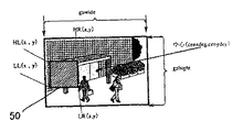
さて、この複合カメラでは、図1に示すように、画像に映るプライバシーゾーンをマスク50によって覆い隠すことができる。オートトレースにより方向を緩やかに変えながら画像が撮像される場合には、カメラの動きに応じて画面上でマスク位置が変化し、プライバシーゾーンを隠し続ける。ただし、この実施形態の複合カメラでは、カメラの速度が一定値以上に速い場合には、マスクが無くてもプライバシーゾーンを画像から識別することができないため、マスクでの遮蔽は行わないこととしている。また、チルト角度が−45〜45度の間には、マスク領域を設けないこととしている。これは、後述するように、チルト角度が小さいと、パン回転によって被写体が相対的に大きく回転し、マスクが有効に作用しない場合があること、また、そのような位置にプライバシーゾーンがある場所では、監視カメラが通常設置されないことなどを理由としている。
【0037】
このマスクの設定は、パソコン19を使って、次のように行われる。
【0038】
操作者が、パソコン19からマスク設定手順を選択すると、複合カメラにマスク設定のコマンドが送られる。カメラ制御部21は、このコマンドを解釈して、レンズ制御部34にズームを最大にするように指示する。このカメラの画像とその状態量を表すPi、Ti、Zp及びZtのデータとがパソコン19に送られ、その画像が画面に表示される。
【0039】
操作者が、マウスを用いて、画像のプライバシーゾーンの中心位置を指定すると、その位置に対応するパン座標及び正のチルト座標がパソコンで算出されて複合カメラに送られ、カメラ制御部21は、そのパン座標及びチルト座標に画面の中心を向けるようにモータ制御部22を指令する。その結果、パソコンの画面の中心にマスク設定の中心位置が来るように画像が表示される。
【0040】
次に、操作者が画面上でカーソルを移動すると、図3に示すように、中心位置を中心に持ち、カーソル位置が1つの角となる四角形のゾーン枠が表示される。このゾーン枠の縦:横の比は、画面の縦横と同じ、3:4に固定されている。操作者は、プライバシーゾーンが隠れるようにゾーン枠を広げた後、マスクゾーン設定の操作を行う。このとき、マスクゾーンを表す番号または名称を併せて設定する。
【0041】
設定されたマスクゾーンを規定する中心座標及び1頂点の座標は、番号とともに、パソコンでデータ管理される。また、パソコンから複合カメラには、そのマスクゾーンを表すパン座標及びチルト座標が、番号とともに送られて、メモリ47に格納される。マスクゾーンは、1画面について最大4個を設定することができる。
【0042】
このとき、パソコンは、マスクゾーンの管理データである中心座標及び1頂点の座標から、マスクゾーンの三隅の座標データを算出し、この座標データを複合カメラに送る。あるいは、マスクゾーンの管理データである中心座標及び1頂点の座標を複合カメラに送り、複合カメラがこの管理データを記憶し、必要なときに、マスクゾーンの四隅の座標データを算出するようにしても良い。
【0043】
図4には、1つのマスクゾーンに対応して複合カメラのメモリ47に格納されるデータを示している。1つのマスクゾーンに対して、図4(a)に示す、左上端HL、左下端LL及び右上端HRの3点のデータ(HLy、LLy、HRy、HLx、LLx、HRx)が格納される。右下端LRのデータは、LRx=HRx、LRy=LLyにより算出される。
【0044】
なお、マスクゾーン設定を画面中央で行うのは、設定時の画像の歪みを防止するためである。
【0045】
また、ゾーン枠の縦:横比を固定しているのは、管理するデータ量を少なくするためである。
【0046】
こうしてマスクゾーンが設定された後の複合カメラにおけるプライバシーゾーン表示処理について説明する。
【0047】
図2は、この複合カメラの動作をフロー図で示している。
ステップ1:カメラ制御部21は、パン移動速度またはチルト移動速度が予め定められた速度以上であるかを調べ、そうであるときは、プライバシーゾーン表示処理を行わない。
【0048】
ステップ2:また、チルト角度Tiが−45〜45度の間にあるかを調べ、そうであるときはプライバシーゾーン表示処理を行わない。
【0049】
ステップ3:チルト角度Tiが負であるときは、
ステップ4:パン角度Piを180度反対の角度に変換する。即ち、Pi<180゜の場合には(Pi+180゜)をパン角度とし、Pi≧180゜の場合には(Pi−180゜)をパン角度とする。また、
ステップ5:チルト角度を(90゜−Ti)に変換する。
このステップ4及びステップ5の処理により、パン絶対座標(0〜360゜)及びチルト絶対座標(0〜180゜)への変換が行われたことになる。
【0050】
ステップ6:カメラ制御部21は、メモリ47からマスクデータを読み出す。
ステップ7:現在、上下反転中であるかを調べ、上下反転中であるときは、
ステップ8:マスクデータのHLとLLとを入れ換え、また、HRとLRとを入れ換える。
図5(a)には、入れ換え処理後のデータ(tHL、tLL、tHR、tLR)を示し、図5(b)には、入れ換え処理が不要であるときのデータを示している。
【0051】
ステップ9:現在、左右反転中であるかを調べ、左右反転中であるときは、
ステップ10:LLとLRとを入れ換え、また、HLとHRとを入れ換える。
図6(a)には、入れ換え処理後のデータ(tHL、tLL、tHR、tLR)を示し、図6(b)には、入れ換え処理が不要であるときのデータを示している。
【0052】
ステップ11:次に、カメラ制御部21は、絶対座標で表したマスクデータを画面座標に変換する。これは、図7に示すように、中心が(Pi,Ti)、水平方向の長さがZp、垂直方向の長さがZtである現在の画面に、マスクゾーン(tHL、tLL、tHR、tLR)を区画するための変換処理であり、図7(a)に示すように、マスクゾーンが現在の画面から外れている場合には、tHLとtHR、tLLとtLRがともに現在の画面の境界線上に変換され(tHL=tHR、tLL=tLR)、マスクゾーンの表示は行われない。
【0053】
また、図7(b)に示すように、マスクゾーンの一部が現在の画面から外れている場合には、外れているマスクゾーンデータ(tHL、tHR、tLL)が画面の境界線上に変換され、変換されたそれらの点とtLRとで区画されるゾーンがマスクゾーンとして表示される。また、図7(c)に示すように、マスクゾーンデータの全てが現在の画面の中に位置する場合は、(tHL、tLL、tHR、tLR)で区画されるエリアがマスクゾーンとして表示される。
【0054】
ステップ12:画面座標に変換されたマスクゾーンがCCD45の画素に対応するデータに変換されてDSP45に出力され、
ステップ13:表示処理が行われる。
【0055】
このマスクゾーンは、画面上で黒などの色で表示され、あるいは、マスク番号や記号(民家マーク、トイレマーク)などが表示される。
【0056】
マスクゾーンを修正する場合には、操作者は、マスク番号を入力してマスク設定手順を実行する。複合カメラのカメラ制御部21は、メモリ47に格納されている該当する番号のマスクデータを読み出し、そのマスクゾーンが画面の中央に来るようにモータ制御部22を制御する。マスクゾーンが画面の中央に表示された状態で操作者がパン/チルトやズームなどの操作を行うとそのゾーンが消去され、新たなゾーンの設定が可能になる。
【0057】
また、図8に示すように、被写体が固定されていても、パン回転に伴って、被写体の画像は画面中で回転する。この変化はチルト角度が真下に近くなる程、大きく現れる。そのため、パン角度がマスク設定時の角度から変化すると、プライバシーゾーンが画面中で回転してマスクから漏れ出る部分が発生する。この問題は、マスクゾーン設定時のパン角度及び現在のパン角度を基に、現在のプライバシーゾーン(=設定時のマスク位置)を覆うために必要なマスクゾーンを計算で求め、マスクを更新することにより避けることができる。
【0058】
また、画角が大きい場合には、小さいマスクをオフにしてもプライバシーを損なう恐れがない。従って、画角によってマスキングのオン/オフを制御するようにしても良い。また、モニタ画面上で一定以上小さくなったマスクは、それ以上小さくしないように制御してもよい。こうした処置により、画角に追随してマスク面積を可変する演算処理が軽減される。また、あまりに小さいマスクは、画像の欠陥と誤解される恐れがある。
【0059】
また、先に、カメラの回転速度が速い場合に、マスキングを停止する処理について説明したが、これは、マスクゾーンの座標計算などがカメラの速い回転に追いつかないための対策でもある。逆に、マスキングの演算が追従できる程度にカメラの回転速度を抑制する制御を行うようにしても良い。
【0060】
また、パソコンは、マスキングの数をカウントし、規定数を超えた場合には、マスクゾーンの設定を不許可にする機能を有する。マスキング数が多すぎると、複合カメラでの処理が追いつかなくなるからである。この場合、複数のプライバシーゾーンを1つのマスクで覆い、マスク数を減らすことにより対処できる。また、1画面に複数のマスクが含まれる場合にも、それらを全て含む一つの拡大マスクに変換してマスキング処理を行うことにより、処理時間の短縮を図ることができる。
【0061】
また、マスキングの解除及び設定は、パスワードを有する特定の人のみが実施できるようにし、一般人が恣意的に操作することを防いでいる。
【0062】
また、マスクゾーンのデータ管理をし易くするため、中心座標と、四角形の一つの頂点とでマスクゾーンを設定する場合について説明したが、左下及び右上の2つの頂点や、中央座標とマスク半径などの形状サイズパラメータを用いることも可能である。
【0063】
また、実施形態では、360度のパン回転及び180度のチルト回転が可能な監視カメラについて説明したが、本発明は、その他のパン回転及びチルト回転を行う監視カメラに対しても、同じように適用することができる。
【0064】
【発明の効果】
以上の説明から明らかなように、本発明の監視カメラでは、プライバシーの保護が必要な画面のエリアだけをマスキングしているため、監視機能を損なうことなく、プライバシーを守ることができる。
【0065】
この装置では、マスクデータをカメラ側で保持しているため、コントローラの側から制御するシステムと違って、伝送遅延による制御の遅れなどが無く、即時性を備え、優れた応答性を発揮することができる。
【図面の簡単な説明】
【図1】実施形態の複合カメラによるマスキングされた表示画面を示す図、
【図2】実施形態の複合カメラの動作を示すフロー図、
【図3】実施形態の複合カメラの表示方法において、マスクゾーン設定画面を示す図、
【図4】実施形態の複合カメラの表示方法において、マスクゾーンの座標を説明する説明図、
【図5】実施形態の複合カメラの表示方法において、上下反転時の座標変換を示す図、
【図6】実施形態の複合カメラの表示方法において、左右反転時の座標変換を示す図、
【図7】実施形態の複合カメラの表示方法において、画面座標への変換を示す図、
【図8】実施形態の複合カメラの表示方法において、パン回転に伴うマスクの修正について説明する説明図、
【図9】実施形態の複合カメラの構造を示す側断面図、
【図10】実施形態の複合カメラの構造を示す平断面図、
【図11】実施形態の複合カメラの構成を示すブロック図、
【図12】第1の実施形態の複合カメラの他の制御系を示す図、
【図13】従来の複合カメラ装置の制御系を示す図、
【図14】従来の複合カメラ装置で行われているカメラ速度制御を説明する説明図、
【図15】従来の複合カメラの動作を説明する図である。
【符号の説明】
10 カメラ
11 複合カメラ
12 コントローラ
13 モニタ
14 ジョイステック
15 テンキー
18 RS485シリアル通信部
19 パソコン
21 カメラ制御部
22 モータ制御部
23、27 モータドライバ
24、28 モータ
25、29 エンコーダ
26、30 減速機構
31 ホール素子検出部
32 原点ホール素子
33 端点ホール素子
34 レンズ制御部
35、39 モータドライバ
36、40 ステッパモータ
37、41 減速機構
38 リミットスイッチ/フォトインタラプタ
42 フォトインタラプタ
43 ドライバ
44 CCD
45 DSP
46 画像メモリ
47 メモリ(E2PROM)
50 マスク
102 カメラ
103 パン回転台
105 チルト回転台
106 チルト回転軸
107 カメラベース
112 スリップリング
113 支柱
117 磁石[0001]
BACKGROUND OF THE INVENTION
The present invention relates to a surveillance camera having a surveillance area of 360 degrees and an image display method thereof, and in particular, allows a part of an image to be masked and displayed for privacy protection.
[0002]
[Prior art]
Conventionally, a surveillance camera in which a camera and a camera turntable are housed in a dome-shaped housing is commercially available. This surveillance camera is called a composite camera because it can perform both horizontal camera rotation (pan) and vertical camera rotation (tilt) by the operation of a turntable. An endless rotation of 360 degrees is possible in the pan direction, and a rotation from 0 degrees to 90 degrees, that is, a horizontal to vertical direction is possible in the tilt direction. This composite camera is installed on the ceiling of a public facility or the like, and can capture a desired direction by operating a controller. Further, even when the subject being tracked passes directly below, as shown in FIG. 15, at the moment when the
[0003]
FIG. 13 shows a state in which the controller 12 that controls the
[0004]
In the
[0005]
The
[0006]
Also, when installing these cameras for public place surveillance, when the camera rotation angle is limited or the direction of the house is photographed so that nearby private houses are not displayed on the screen. A function for image processing is added so that the entire image becomes black, thereby protecting privacy.
[0007]
[Problems to be solved by the invention]
However, the conventional method for protecting privacy in a surveillance camera has a problem in that an image other than the area to be protected cannot be seen due to the limitation of the photographing direction or the darkness of the entire image, and the monitoring function is inevitably lowered.
[0008]
The group of inventors of the present invention has developed a new composite camera that can rotate 360 degrees in the pan direction and rotate 180 degrees in the tilt direction. In this composite camera, a wide range can be functionally monitored due to an increase in the degree of freedom in the moving direction. However, there is a need for a method for protecting privacy without diminishing these functions.
[0009]
The present invention solves these problems and can protect privacy from the image of the camera without impairing the monitoring function. Surveillance camera The purpose is to provide.
[0010]
[Means for Solving the Problems]
Therefore, in the present invention, in the surveillance camera device including the surveillance camera capable of pan rotation and tilt rotation and the control device thereof, the surveillance camera holds mask data for masking the privacy zone shown in the image, and according to this data, A part of the image is masked.
[0012]
Therefore, since only a part of the image is hidden, the privacy can be protected without impairing the monitoring function.
[0013]
Further, in this apparatus, since the monitoring camera holds the masking data, it is possible to respond quickly.
[0014]
DETAILED DESCRIPTION OF THE INVENTION
(First embodiment)
As shown in the side sectional view of FIG. 9 and the plan view of FIG. 10, the composite camera according to the embodiment of the present invention includes a surveillance camera in a housing composed of a
[0015]
The tilt turntable 105 that holds the camera 102 can be rotated 180 degrees around the tilt rotation axis 106. As a result, the camera 102 moves from the direction of point A (108) in FIG. The direction can be reversibly changed through the point B (109) to the direction of the point C (110).
[0016]
Further, the pan turntable 103 can rotate the rotation locus 206 in the horizontal direction over 360 degrees as shown in FIG.
[0017]
In addition, the slip ring 112 realizes power supply from the fixed portion to the movable portion and electrical signal conduction between the fixed portion and the movable portion.
[0018]
Therefore, by mounting this composite camera on the ceiling, adjusting the rotation angle of the tilt turntable 105 by remote control, and rotating the pan turntable 103 in a predetermined direction, the camera 102 captures all directions in the monitoring area. be able to.
[0019]
FIG. 11 shows the internal configuration of this composite camera in function blocks. As the rotation control mechanism of the pan turntable 103 and the tilt turntable 105, the
[0020]
Further, as a control mechanism of the camera lens unit,
[0021]
In addition, the camera unit that outputs the video signal includes a CCD 44 that performs imaging, a
[0022]
Furthermore, a
[0023]
Further, the composite camera is controlled by being connected to the controller 12 and the
[0024]
In this example, a single
[0025]
First, the general operation of this composite camera will be described. In this composite camera, the output pulse of the encoder 25 that detects the rotation of the
Pi = m × 360 / p
To calculate the current pan angle Pi. The calculated current pan angle Pi is held in the memory 47.
[0026]
Similarly, the output pulse of the
Ti = 90− (n × 180 / q)
Thus, the current tilt angle Ti is calculated. That is, the tilt angle is calculated with the direction immediately below as 0 degrees. The range in which the tilt angle can be taken is from +90 degrees to -90 degrees. The calculated current tilt angle Ti is held in the memory 47.
[0027]
The pan angle Pi and the tilt angle Ti indicate the direction of the center of the current camera screen.
[0028]
In addition, the angle of view of the captured image is determined by the rotation amount of the
[0029]
Thus, Pi, Ti, Zt and Zp are stored in the memory 47 as data representing the current state quantity of the composite camera.
[0030]
The operation of the composite camera is controlled by the controller 12 or the
[0031]
When the operator tilts the
[0032]
When the operator returns the joystick to the neutral position, data of Vpan = 0 and Vtilt = 0 is sent to the composite camera together with the command, and rotation in the tilt direction and the pan direction is stopped.
[0033]
When the camera changes its direction, as described above, Pi, Ti, Zt, and Zp data representing the current state of the camera are updated and held.
[0034]
The CCD 44 images the direction in which the camera is directed and outputs the video signal to the
[0035]
Similarly, when the camera is rotated 90 degrees horizontally, the tilt angle is not moved and the pan angle can be turned 90 degrees, and the tilt angle is temporarily set to 0 while the pan angle is fixed. It can also be realized by a method of pulling up in a different direction after 90 degrees. In the latter case, it is necessary to read the image data of the CCD 44 through the image memory 46 with the left and right reversed. This state will be referred to as “horizontal inversion”.
[0036]
In this composite camera, as shown in FIG. 1, the privacy zone reflected in the image can be covered with a
[0037]
This mask setting is performed using the
[0038]
When the operator selects a mask setting procedure from the
[0039]
When the operator designates the center position of the privacy zone of the image using the mouse, pan coordinates and positive tilt coordinates corresponding to the position are calculated by a personal computer and sent to the composite camera. The
[0040]
Next, when the operator moves the cursor on the screen, as shown in FIG. 3, a rectangular zone frame having the center position at the center and the cursor position as one corner is displayed. The vertical / horizontal ratio of the zone frame is fixed at 3: 4, which is the same as the vertical / horizontal direction of the screen. The operator performs the mask zone setting operation after expanding the zone frame so that the privacy zone is hidden. At this time, a number or name representing the mask zone is also set.
[0041]
The central coordinates defining the set mask zone and the coordinates of one vertex are managed by a personal computer together with a number. Also, pan coordinates and tilt coordinates representing the mask zone are sent together with the number from the personal computer to the composite camera and stored in the memory 47. Up to four mask zones can be set for one screen.
[0042]
At this time, the personal computer calculates the coordinate data of the three corners of the mask zone from the center coordinates and the coordinates of one vertex, which are the management data of the mask zone, and sends this coordinate data to the composite camera. Alternatively, the central coordinates and the coordinates of one vertex which are management data of the mask zone are sent to the composite camera, the composite camera stores this management data, and calculates the coordinate data of the four corners of the mask zone when necessary. Also good.
[0043]
FIG. 4 shows data stored in the memory 47 of the composite camera corresponding to one mask zone. Data of three points (HLy, LLy, HRy, HLx, LLx, HRx) shown in FIG. 4A are stored in one mask zone, which are the upper left end HL, the lower left end LL, and the upper right end HR. The data of the lower right LR is calculated by LRx = HRx and LRy = LLy.
[0044]
The reason for setting the mask zone at the center of the screen is to prevent distortion of the image at the time of setting.
[0045]
The reason why the aspect ratio of the zone frame is fixed is to reduce the amount of data to be managed.
[0046]
The privacy zone display process in the composite camera after the mask zone is set in this way will be described.
[0047]
FIG. 2 is a flowchart showing the operation of the composite camera.
Step 1: The
[0048]
Step 2: Further, it is checked whether the tilt angle Ti is between −45 and 45 degrees. If so, the privacy zone display process is not performed.
[0049]
Step 3: When the tilt angle Ti is negative,
Step 4: The pan angle Pi is converted to an opposite angle of 180 degrees. That is, when Pi <180 °, (Pi + 180 °) is the pan angle, and when Pi ≧ 180 °, (Pi−180 °) is the pan angle. Also,
Step 5: Convert the tilt angle to (90 ° -Ti).
By the processing of step 4 and step 5, conversion to pan absolute coordinates (0 to 360 °) and tilt absolute coordinates (0 to 180 °) is performed.
[0050]
Step 6: The
Step 7: Check if it is currently upside down. If it is upside down,
Step 8: The mask data HL and LL are exchanged, and the HR and LR are exchanged.
FIG. 5A shows data (tHL, tLL, tHR, tLR) after the replacement process, and FIG. 5B shows data when the replacement process is unnecessary.
[0051]
Step 9: Check if it is currently flipping horizontally. If it is flipping horizontally,
Step 10: Swap LL and LR, and swap HL and HR.
FIG. 6A shows data (tHL, tLL, tHR, tLR) after the replacement process, and FIG. 6B shows data when the replacement process is unnecessary.
[0052]
Step 11: Next, the
[0053]
In addition, as shown in FIG. 7B, when a part of the mask zone is out of the current screen, the mask zone data (tHL, tHR, tLL) out of the screen is converted to the screen boundary. A zone defined by these converted points and tLR is displayed as a mask zone. Further, as shown in FIG. 7C, when all of the mask zone data is located in the current screen, an area defined by (tHL, tLL, tHR, tLR) is displayed as a mask zone. .
[0054]
Step 12: The mask zone converted into the screen coordinates is converted into data corresponding to the pixels of the
Step 13: Display processing is performed.
[0055]
The mask zone is displayed in a color such as black on the screen, or a mask number or a symbol (private house mark, toilet mark) or the like is displayed.
[0056]
When correcting the mask zone, the operator inputs the mask number and executes the mask setting procedure. The
[0057]
As shown in FIG. 8, even if the subject is fixed, the subject image rotates in the screen as the pan rotates. This change becomes more significant as the tilt angle becomes closer to the bottom. For this reason, when the pan angle changes from the angle at the time of mask setting, the privacy zone rotates in the screen and a portion leaking from the mask occurs. The problem is that the mask zone necessary to cover the current privacy zone (= mask position at the time of setting) is calculated based on the pan angle at the time of setting the mask zone and the current pan angle, and the mask is updated. Can be avoided.
[0058]
In addition, when the angle of view is large, there is no risk of losing privacy even if the small mask is turned off. Therefore, masking on / off may be controlled by the angle of view. Further, a mask that has become smaller than a certain value on the monitor screen may be controlled so as not to be further reduced. By such a treatment, the arithmetic processing for changing the mask area following the angle of view is reduced. Also, a mask that is too small can be mistaken for an image defect.
[0059]
In addition, the process of stopping masking when the rotation speed of the camera is fast has been described above, but this is also a measure for preventing the coordinate calculation of the mask zone from catching up with the fast rotation of the camera. Conversely, control may be performed to suppress the rotational speed of the camera to the extent that the masking calculation can follow.
[0060]
In addition, the personal computer has a function of counting the number of masking and disabling the mask zone setting when the specified number is exceeded. This is because if the number of masking is too large, the processing by the composite camera cannot catch up. In this case, this can be dealt with by covering a plurality of privacy zones with one mask and reducing the number of masks. Even when a plurality of masks are included in one screen, the processing time can be shortened by converting the mask into one enlarged mask including all of them and performing the masking process.
[0061]
In addition, the masking can be canceled and set only by a specific person having a password, thereby preventing an ordinary person from performing arbitrary operations.
[0062]
In addition, in order to facilitate the data management of the mask zone, the case where the mask zone is set with the center coordinates and one vertex of the rectangle has been described. It is also possible to use the shape size parameter.
[0063]
Further, in the embodiment, the surveillance camera capable of 360-degree pan rotation and 180-degree tilt rotation has been described, but the present invention is similarly applied to other surveillance cameras that perform pan rotation and tilt rotation. Can be applied.
[0064]
【The invention's effect】
As is clear from the above description, the present invention Surveillance camera Since only the screen area that needs privacy protection is masked, privacy can be protected without impairing the monitoring function.
[0065]
In this device, the mask data is held on the camera side, so unlike the system that controls from the controller side, there is no delay in control due to transmission delay, etc., and it has immediacy and exhibits excellent responsiveness. Can do.
[Brief description of the drawings]
FIG. 1 is a diagram showing a masked display screen by a composite camera of an embodiment;
FIG. 2 is a flowchart showing the operation of the composite camera of the embodiment;
FIG. 3 is a diagram showing a mask zone setting screen in the composite camera display method of the embodiment;
FIG. 4 is an explanatory diagram for explaining the coordinates of a mask zone in the composite camera display method according to the embodiment;
FIG. 5 is a diagram showing coordinate conversion at the time of upside down in the display method of the composite camera of the embodiment;
FIG. 6 is a diagram showing coordinate conversion at the time of horizontal reversal in the display method of the composite camera of the embodiment;
FIG. 7 is a diagram showing conversion to screen coordinates in the composite camera display method of the embodiment;
FIG. 8 is an explanatory diagram for explaining correction of a mask accompanying pan rotation in the display method of the composite camera of the embodiment;
FIG. 9 is a side sectional view showing the structure of the composite camera of the embodiment;
FIG. 10 is a plan sectional view showing the structure of the composite camera of the embodiment;
FIG. 11 is a block diagram showing the configuration of the composite camera of the embodiment;
FIG. 12 is a diagram showing another control system of the composite camera of the first embodiment;
FIG. 13 is a diagram showing a control system of a conventional composite camera device;
FIG. 14 is an explanatory diagram for explaining camera speed control performed in a conventional composite camera device;
FIG. 15 is a diagram illustrating the operation of a conventional composite camera.
[Explanation of symbols]
10 Camera
11 Combined camera
12 Controller
13 Monitor
14 Joyce Tech
15 Numeric keypad
18 RS485 serial communication section
19 PC
21 Camera control unit
22 Motor controller
23, 27 Motor driver
24, 28 motor
25, 29 Encoder
26, 30 Deceleration mechanism
31 Hall element detector
32 Origin Hall element
33 End Hall element
34 Lens control unit
35, 39 Motor driver
36, 40 Stepper motor
37, 41 Deceleration mechanism
38 Limit switch / Photo interrupter
42 Photointerrupter
43 Drivers
44 CCD
45 DSP
46 Image memory
47 Memory (E 2 PROM)
50 mask
102 Camera
103 Pan turntable
105 tilt turntable
106 Tilt rotation axis
107 camera base
112 slip ring
113 support
117 magnet
Claims (3)
Priority Applications (5)
| Application Number | Priority Date | Filing Date | Title |
|---|---|---|---|
| JP24619499A JP3722653B2 (en) | 1999-08-31 | 1999-08-31 | Surveillance camera device and display method of surveillance camera |
| US09/649,173 US6744461B1 (en) | 1999-08-31 | 2000-08-29 | Monitor camera system and method of displaying picture from monitor camera thereof |
| AU55073/00A AU5507300A (en) | 1999-08-31 | 2000-08-31 | Monitor camera system and method of displaying picture from monitor camera thereof |
| DE60031059T DE60031059T2 (en) | 1999-08-31 | 2000-08-31 | Video camera observation system and apparatus for displaying images from this video observation camera |
| EP00307514A EP1081955B1 (en) | 1999-08-31 | 2000-08-31 | Monitor camera system and method of displaying picture from monitor camera thereof |
Applications Claiming Priority (1)
| Application Number | Priority Date | Filing Date | Title |
|---|---|---|---|
| JP24619499A JP3722653B2 (en) | 1999-08-31 | 1999-08-31 | Surveillance camera device and display method of surveillance camera |
Related Child Applications (1)
| Application Number | Title | Priority Date | Filing Date |
|---|---|---|---|
| JP2004187738A Division JP3767615B2 (en) | 2004-06-25 | 2004-06-25 | Surveillance camera device and monitoring camera display method |
Publications (2)
| Publication Number | Publication Date |
|---|---|
| JP2001069494A JP2001069494A (en) | 2001-03-16 |
| JP3722653B2 true JP3722653B2 (en) | 2005-11-30 |
Family
ID=17144919
Family Applications (1)
| Application Number | Title | Priority Date | Filing Date |
|---|---|---|---|
| JP24619499A Expired - Lifetime JP3722653B2 (en) | 1999-08-31 | 1999-08-31 | Surveillance camera device and display method of surveillance camera |
Country Status (5)
| Country | Link |
|---|---|
| US (1) | US6744461B1 (en) |
| EP (1) | EP1081955B1 (en) |
| JP (1) | JP3722653B2 (en) |
| AU (1) | AU5507300A (en) |
| DE (1) | DE60031059T2 (en) |
Cited By (1)
| Publication number | Priority date | Publication date | Assignee | Title |
|---|---|---|---|---|
| US12323182B2 (en) | 2020-01-30 | 2025-06-03 | Nec Corporation | Processing device, processing method, and recording medium |
Families Citing this family (109)
| Publication number | Priority date | Publication date | Assignee | Title |
|---|---|---|---|---|
| US7907793B1 (en) | 2001-05-04 | 2011-03-15 | Legend Films Inc. | Image sequence depth enhancement system and method |
| US8396328B2 (en) | 2001-05-04 | 2013-03-12 | Legend3D, Inc. | Minimal artifact image sequence depth enhancement system and method |
| JP2001069496A (en) * | 1999-08-31 | 2001-03-16 | Matsushita Electric Ind Co Ltd | Surveillance camera device and control method of surveillance camera |
| JP2002010124A (en) * | 2000-06-21 | 2002-01-11 | Matsushita Electric Ind Co Ltd | Camera operation device |
| JP4556088B2 (en) * | 2001-05-02 | 2010-10-06 | ソニー株式会社 | Image processing system, image processing apparatus, and control method thereof |
| US9286941B2 (en) | 2001-05-04 | 2016-03-15 | Legend3D, Inc. | Image sequence enhancement and motion picture project management system |
| US8897596B1 (en) | 2001-05-04 | 2014-11-25 | Legend3D, Inc. | System and method for rapid image sequence depth enhancement with translucent elements |
| US9031383B2 (en) | 2001-05-04 | 2015-05-12 | Legend3D, Inc. | Motion picture project management system |
| US8401336B2 (en) * | 2001-05-04 | 2013-03-19 | Legend3D, Inc. | System and method for rapid image sequence depth enhancement with augmented computer-generated elements |
| EP1405269A2 (en) * | 2001-05-04 | 2004-04-07 | Legend Films, Llc | Image sequence enhancement system and method |
| JP2003061076A (en) * | 2001-08-10 | 2003-02-28 | Sogo Keibi Hosho Co Ltd | Supervisory device, supervisory method and program for making computer execute the method |
| DE10158990C1 (en) | 2001-11-30 | 2003-04-10 | Bosch Gmbh Robert | Video surveillance system incorporates masking of identified object for maintaining privacy until entry of authorisation |
| US7893959B2 (en) | 2002-01-22 | 2011-02-22 | Sanyo Electric Co., Ltd. | Video display system for correcting the position and size of mask images |
| JP2003259189A (en) | 2002-03-01 | 2003-09-12 | Sony Corp | Imaging device, image processing method |
| US7468778B2 (en) | 2002-03-15 | 2008-12-23 | British Broadcasting Corp | Virtual studio system |
| JP3996805B2 (en) | 2002-06-06 | 2007-10-24 | 株式会社日立製作所 | Surveillance camera device, surveillance camera system device, and imaging screen mask method |
| JP2004021495A (en) | 2002-06-14 | 2004-01-22 | Mitsubishi Electric Corp | Monitoring system and monitoring method |
| JP3770859B2 (en) | 2002-08-22 | 2006-04-26 | 株式会社日立国際電気 | Surveillance camera device |
| JP2004146890A (en) * | 2002-10-22 | 2004-05-20 | Hitachi Ltd | Surveillance camera device and surveillance camera system device |
| US20040100563A1 (en) | 2002-11-27 | 2004-05-27 | Sezai Sablak | Video tracking system and method |
| DE602004015173D1 (en) | 2003-01-21 | 2008-09-04 | Canon Kk | Imaging device and image acquisition system |
| WO2004080064A1 (en) * | 2003-03-06 | 2004-09-16 | Fujitsu Limited | Information processing deice, information processing method, and information processing program |
| GB2411229B (en) | 2003-07-22 | 2006-04-12 | Hitachi Int Electric Inc | Object tracking method and object tracing apparatus |
| JP3938127B2 (en) * | 2003-09-29 | 2007-06-27 | ソニー株式会社 | Imaging device |
| KR100588170B1 (en) | 2003-11-20 | 2006-06-08 | 엘지전자 주식회사 | How to Set Privacy Masking in Surveillance Cameras |
| US7382400B2 (en) * | 2004-02-19 | 2008-06-03 | Robert Bosch Gmbh | Image stabilization system and method for a video camera |
| US7742077B2 (en) | 2004-02-19 | 2010-06-22 | Robert Bosch Gmbh | Image stabilization system and method for a video camera |
| JP4509619B2 (en) * | 2004-03-24 | 2010-07-21 | 株式会社日立製作所 | Video processing device operation program |
| JP4846203B2 (en) * | 2004-03-24 | 2011-12-28 | パナソニック株式会社 | Image area setting apparatus and image area setting method |
| US9210312B2 (en) | 2004-06-02 | 2015-12-08 | Bosch Security Systems, Inc. | Virtual mask for use in autotracking video camera images |
| US8212872B2 (en) | 2004-06-02 | 2012-07-03 | Robert Bosch Gmbh | Transformable privacy mask for video camera images |
| TW200603016A (en) * | 2004-07-09 | 2006-01-16 | Avermedia Tech Inc | Surveillance system and surveillance method |
| JP2006086714A (en) * | 2004-09-15 | 2006-03-30 | Elmo Co Ltd | Surveillance camera device |
| US8860780B1 (en) * | 2004-09-27 | 2014-10-14 | Grandeye, Ltd. | Automatic pivoting in a wide-angle video camera |
| KR100664350B1 (en) | 2004-12-03 | 2007-01-02 | 엘지전자 주식회사 | Privacy mask display control method |
| US7493038B2 (en) * | 2004-12-15 | 2009-02-17 | Lg Electronics Inc. | Method and apparatus for controlling privacy mask display |
| KR100664351B1 (en) * | 2004-12-15 | 2007-01-02 | 엘지전자 주식회사 | Privacy mask display control device and method using optical axis offset value |
| KR100771137B1 (en) * | 2005-02-21 | 2007-10-30 | 삼성전자주식회사 | Surveillance system to mask privacy area and mask area setting method |
| KR100719120B1 (en) * | 2005-02-26 | 2007-05-17 | 삼성전자주식회사 | Monitoring system and method for masking privacy area |
| KR101113844B1 (en) * | 2005-03-08 | 2012-02-29 | 삼성테크윈 주식회사 | A supervisory camera and a privacy protecting method of the supervisory camera |
| JP4696660B2 (en) * | 2005-04-25 | 2011-06-08 | ソニー株式会社 | Image processing apparatus and surveillance camera apparatus |
| US20070065102A1 (en) * | 2005-09-16 | 2007-03-22 | Laughlin Richard H | System and method for detecting real-time change in an image |
| JP4680033B2 (en) * | 2005-11-01 | 2011-05-11 | 三菱電機株式会社 | Monitoring system and monitoring device |
| KR101187756B1 (en) * | 2005-11-07 | 2012-10-08 | 엘지전자 주식회사 | Method for controlling privacy mask display of monitoring camera |
| CN1767638B (en) * | 2005-11-30 | 2011-06-08 | 北京中星微电子有限公司 | Visible image monitoring method for protecting privacy right and its system |
| JP2007166313A (en) * | 2005-12-14 | 2007-06-28 | Matsushita Electric Ind Co Ltd | Camera device and wiper control method |
| EP1804511A1 (en) * | 2005-12-30 | 2007-07-04 | Nederlandse Organisatie voor Toegepast-Natuuurwetenschappelijk Onderzoek TNO | A monitoring system, a method for monitoring, a computer system and a computer program product |
| CN101453616B (en) * | 2006-06-15 | 2011-09-14 | 北京中星微电子有限公司 | Camera shooting device |
| JP4270230B2 (en) * | 2006-07-11 | 2009-05-27 | ソニー株式会社 | Imaging apparatus and method, image processing apparatus and method, and program |
| JP4940820B2 (en) * | 2006-08-09 | 2012-05-30 | パナソニック株式会社 | Network camera |
| JP4290185B2 (en) * | 2006-09-05 | 2009-07-01 | キヤノン株式会社 | Imaging system, imaging apparatus, monitoring apparatus, and program |
| JP5183054B2 (en) * | 2006-10-12 | 2013-04-17 | 中国電力株式会社 | Security device |
| JP4671133B2 (en) * | 2007-02-09 | 2011-04-13 | 富士フイルム株式会社 | Image processing device |
| JP5108323B2 (en) * | 2007-02-14 | 2012-12-26 | パナソニック株式会社 | Surveillance camera and surveillance camera control method |
| EP1959692B9 (en) * | 2007-02-19 | 2011-06-22 | Axis AB | A method for compensating hardware misalignments in a camera |
| US8831299B2 (en) * | 2007-05-22 | 2014-09-09 | Intellectual Ventures Fund 83 Llc | Capturing data for individual physiological monitoring |
| WO2008149925A1 (en) * | 2007-06-08 | 2008-12-11 | Nikon Corporation | Imaging device, image display device, and program |
| DE102007029606B3 (en) * | 2007-06-27 | 2009-01-15 | Siemens Ag | Video surveillance method for parking place of residential house, involves determining moving image object in recorded video images, where preset region in recorded video image outside of moving image object is garbled |
| JP2009017183A (en) * | 2007-07-04 | 2009-01-22 | Panasonic Corp | Surveillance camera device |
| US8098282B2 (en) * | 2007-07-13 | 2012-01-17 | Honeywell International Inc. | Privacy zone algorithm for ptz dome cameras |
| JP2009124618A (en) * | 2007-11-19 | 2009-06-04 | Hitachi Ltd | Camera device, image processing device |
| KR101453087B1 (en) * | 2008-01-24 | 2014-10-27 | 엘지전자 주식회사 | Apparatus and method for controlling mask color of surveillance camera |
| JP5002506B2 (en) | 2008-03-26 | 2012-08-15 | 株式会社エルモ社 | Camera system |
| US8311275B1 (en) | 2008-06-10 | 2012-11-13 | Mindmancer AB | Selective viewing of a scene |
| JP5352150B2 (en) | 2008-08-01 | 2013-11-27 | パナソニック株式会社 | Imaging device |
| JP5471224B2 (en) * | 2009-09-15 | 2014-04-16 | ソニー株式会社 | Imaging system, imaging apparatus, information processing apparatus, and imaging method |
| KR101271461B1 (en) * | 2009-10-09 | 2013-06-05 | 한국전자통신연구원 | Apparatus and method for protecting privacy information of surveillance image |
| JP5566145B2 (en) | 2010-03-18 | 2014-08-06 | キヤノン株式会社 | Image pickup apparatus having masking function and control method thereof |
| JP5471919B2 (en) * | 2010-07-14 | 2014-04-16 | 富士通株式会社 | Image processing apparatus, image processing program, image processing method, and moving body |
| JP5005080B2 (en) * | 2010-09-06 | 2012-08-22 | キヤノン株式会社 | Panorama image generation method |
| CN102572549B (en) | 2010-10-16 | 2016-05-04 | 佳能株式会社 | Server device and video data transmission method |
| US9794518B2 (en) * | 2010-10-21 | 2017-10-17 | Sensormatic Electronics, LLC | Method and system for converting privacy zone planar images to their corresponding pan/tilt coordinates |
| JP5791256B2 (en) | 2010-10-21 | 2015-10-07 | キヤノン株式会社 | Display control apparatus and display control method |
| JP5812593B2 (en) | 2010-10-28 | 2015-11-17 | キヤノン株式会社 | VIDEO PROCESSING DEVICE, IMAGING DEVICE, VIDEO PROCESSING METHOD, AND PROGRAM |
| US8730232B2 (en) | 2011-02-01 | 2014-05-20 | Legend3D, Inc. | Director-style based 2D to 3D movie conversion system and method |
| US9113130B2 (en) | 2012-02-06 | 2015-08-18 | Legend3D, Inc. | Multi-stage production pipeline system |
| US9241147B2 (en) | 2013-05-01 | 2016-01-19 | Legend3D, Inc. | External depth map transformation method for conversion of two-dimensional images to stereoscopic images |
| US9407904B2 (en) | 2013-05-01 | 2016-08-02 | Legend3D, Inc. | Method for creating 3D virtual reality from 2D images |
| US9288476B2 (en) | 2011-02-17 | 2016-03-15 | Legend3D, Inc. | System and method for real-time depth modification of stereo images of a virtual reality environment |
| US9282321B2 (en) | 2011-02-17 | 2016-03-08 | Legend3D, Inc. | 3D model multi-reviewer system |
| JP5871485B2 (en) * | 2011-05-17 | 2016-03-01 | キヤノン株式会社 | Image transmission apparatus, image transmission method, and program |
| JP5389879B2 (en) * | 2011-09-20 | 2014-01-15 | 株式会社日立製作所 | Imaging apparatus, surveillance camera, and camera screen masking method |
| JP5865710B2 (en) * | 2012-01-12 | 2016-02-17 | セコム株式会社 | Image processing device |
| JP5955171B2 (en) | 2012-09-11 | 2016-07-20 | キヤノン株式会社 | TRANSMISSION DEVICE, RECEPTION DEVICE, TRANSMISSION METHOD, RECEPTION METHOD, AND PROGRAM |
| US8914894B2 (en) * | 2012-09-21 | 2014-12-16 | Intel Corporation | Enhanced privacy for provision of computer vision |
| JP6157094B2 (en) * | 2012-11-21 | 2017-07-05 | キヤノン株式会社 | COMMUNICATION DEVICE, SETTING DEVICE, COMMUNICATION METHOD, SETTING METHOD, AND PROGRAM |
| US9007365B2 (en) | 2012-11-27 | 2015-04-14 | Legend3D, Inc. | Line depth augmentation system and method for conversion of 2D images to 3D images |
| JP6112479B2 (en) | 2012-11-29 | 2017-04-12 | パナソニックIpマネジメント株式会社 | Surveillance camera device, surveillance system including the same, mask processing method, and mask processing program |
| US9547937B2 (en) | 2012-11-30 | 2017-01-17 | Legend3D, Inc. | Three-dimensional annotation system and method |
| US9007404B2 (en) | 2013-03-15 | 2015-04-14 | Legend3D, Inc. | Tilt-based look around effect image enhancement method |
| US9438878B2 (en) | 2013-05-01 | 2016-09-06 | Legend3D, Inc. | Method of converting 2D video to 3D video using 3D object models |
| EP3026897A1 (en) | 2013-07-26 | 2016-06-01 | Mitsubishi Electric Corporation | Surveillance camera, video security system, and swivel-type surveillance camera |
| JP6376743B2 (en) | 2013-10-18 | 2018-08-22 | キヤノン株式会社 | IMAGING DEVICE, IMAGING SYSTEM, IMAGING DEVICE CONTROL METHOD, IMAGING SYSTEM CONTROL METHOD, AND PROGRAM |
| JP6429598B2 (en) * | 2014-11-11 | 2018-11-28 | キヤノン株式会社 | Imaging apparatus and control method thereof |
| US9454675B2 (en) * | 2015-01-26 | 2016-09-27 | Idis Co., Ltd. | Apparatus and method for protecting personal information of recorded image, and computer-readable recording medium having computer program recorded therein |
| US9609307B1 (en) | 2015-09-17 | 2017-03-28 | Legend3D, Inc. | Method of converting 2D video to 3D video using machine learning |
| US9881171B2 (en) | 2015-11-16 | 2018-01-30 | International Business Machines Corporation | Privacy protecting sensing devices |
| KR20180066722A (en) * | 2016-12-09 | 2018-06-19 | 한국전자통신연구원 | Mobile based personal content protection apparatus and method therefor |
| CN109670383B (en) * | 2017-10-16 | 2021-01-29 | 杭州海康威视数字技术股份有限公司 | Video shielding area selection method and device, electronic equipment and system |
| US11336831B2 (en) * | 2018-07-06 | 2022-05-17 | Canon Kabushiki Kaisha | Image processing device, control method, and program storage medium |
| JP7253336B2 (en) * | 2018-08-08 | 2023-04-06 | アークレイ株式会社 | Image processing device, image processing system, image processing method, and image processing program |
| JP7134784B2 (en) | 2018-08-20 | 2022-09-12 | 株式会社東芝 | Monitoring system, monitoring method and program |
| CN109283850B (en) * | 2018-09-13 | 2021-08-13 | 广东美的制冷设备有限公司 | Household appliance, control method of household appliance and storage medium |
| JP7328849B2 (en) | 2019-09-25 | 2023-08-17 | キヤノン株式会社 | IMAGING DEVICE, SYSTEM, CONTROL METHOD OF IMAGING DEVICE, AND PROGRAM |
| JP7307643B2 (en) | 2019-09-25 | 2023-07-12 | キヤノン株式会社 | IMAGING DEVICE, SYSTEM, CONTROL METHOD OF IMAGING DEVICE, AND PROGRAM |
| JP2021052325A (en) | 2019-09-25 | 2021-04-01 | キヤノン株式会社 | Image capture device, system, method for controlling image capture device, and program |
| CN110996010A (en) * | 2019-12-20 | 2020-04-10 | 歌尔科技有限公司 | Camera, image processing method and device thereof, and computer storage medium |
| KR20210118616A (en) * | 2020-03-23 | 2021-10-01 | 삼성전자주식회사 | Display apparatus and the control method thereof |
| EP3985976B1 (en) | 2020-10-16 | 2022-09-28 | Axis AB | Method of encoding an image including a privacy mask |
Family Cites Families (12)
| Publication number | Priority date | Publication date | Assignee | Title |
|---|---|---|---|---|
| US4992866A (en) * | 1989-06-29 | 1991-02-12 | Morgan Jack B | Camera selection and positioning system and method |
| JP3189366B2 (en) | 1991-04-05 | 2001-07-16 | 松下電器産業株式会社 | Imaging device |
| CA2062620C (en) * | 1991-07-31 | 1998-10-06 | Robert Paff | Surveillance apparatus with enhanced control of camera and lens assembly |
| JP2778320B2 (en) | 1991-11-30 | 1998-07-23 | 日本電気株式会社 | Remote control surveillance TV camera system |
| JP2661657B2 (en) * | 1992-12-01 | 1997-10-08 | 松下情報システム株式会社 | Image synthesis device |
| JPH0851611A (en) * | 1994-08-05 | 1996-02-20 | Canon Inc | Image processing apparatus and image processing method |
| JPH08212465A (en) | 1995-02-08 | 1996-08-20 | Hochiki Corp | Security system using surveillance cameras |
| JP3265893B2 (en) * | 1995-02-13 | 2002-03-18 | 株式会社日立製作所 | Image display device |
| JPH08223561A (en) * | 1995-02-17 | 1996-08-30 | Nippon Denki Syst Kensetsu Kk | Method and device for controlling camera by the use of monitor area diagram |
| US6768563B1 (en) * | 1995-02-24 | 2004-07-27 | Canon Kabushiki Kaisha | Image input system |
| US6208379B1 (en) * | 1996-02-20 | 2001-03-27 | Canon Kabushiki Kaisha | Camera display control and monitoring system |
| JP3563889B2 (en) * | 1996-10-15 | 2004-09-08 | キヤノン株式会社 | Camera control system and camera control system control method |
-
1999
- 1999-08-31 JP JP24619499A patent/JP3722653B2/en not_active Expired - Lifetime
-
2000
- 2000-08-29 US US09/649,173 patent/US6744461B1/en not_active Expired - Lifetime
- 2000-08-31 EP EP00307514A patent/EP1081955B1/en not_active Expired - Lifetime
- 2000-08-31 AU AU55073/00A patent/AU5507300A/en not_active Abandoned
- 2000-08-31 DE DE60031059T patent/DE60031059T2/en not_active Expired - Lifetime
Cited By (1)
| Publication number | Priority date | Publication date | Assignee | Title |
|---|---|---|---|---|
| US12323182B2 (en) | 2020-01-30 | 2025-06-03 | Nec Corporation | Processing device, processing method, and recording medium |
Also Published As
| Publication number | Publication date |
|---|---|
| DE60031059T2 (en) | 2007-04-19 |
| AU5507300A (en) | 2001-03-08 |
| DE60031059D1 (en) | 2006-11-16 |
| US6744461B1 (en) | 2004-06-01 |
| EP1081955A2 (en) | 2001-03-07 |
| EP1081955A3 (en) | 2001-10-04 |
| JP2001069494A (en) | 2001-03-16 |
| EP1081955B1 (en) | 2006-10-04 |
Similar Documents
| Publication | Publication Date | Title |
|---|---|---|
| JP3722653B2 (en) | Surveillance camera device and display method of surveillance camera | |
| US6977678B1 (en) | Monitor camera system and method of controlling monitor camera thereof | |
| CN102461153B (en) | Control device and camera system | |
| JPH11331822A (en) | Surveillance camera device | |
| JP2001086486A (en) | Surveillance camera system and surveillance camera display method | |
| JP3767615B2 (en) | Surveillance camera device and monitoring camera display method | |
| US7151558B1 (en) | Monitor camera system and auto-tracing implementation method using the same | |
| JP4243883B2 (en) | Remote head system | |
| KR100664350B1 (en) | Privacy mask display control method | |
| JP4544136B2 (en) | Surveillance camera | |
| WO2006121685A1 (en) | Methods and systems for controlling camera movement | |
| JP4063604B2 (en) | Surveillance camera device | |
| JP2778320B2 (en) | Remote control surveillance TV camera system | |
| KR100744870B1 (en) | Apparatus and method for controling pan and tilt for monitoring camera | |
| AU2003204213B2 (en) | Monitor camera system and method of displaying picture from monitor camera thereof | |
| JP3838881B2 (en) | Surveillance camera device | |
| KR100664811B1 (en) | Privacy mask display control method and apparatus | |
| JP2005244550A (en) | Method for generating monitored image | |
| KR20050062859A (en) | Method for positioning a monitoring camera | |
| JPH11242787A (en) | Supervisory system | |
| JP2001103457A (en) | Surveillance camera device and operation method during maintenance and inspection | |
| JPH09159899A (en) | Imaging device | |
| KR101158819B1 (en) | Method for controlling privacy mask display of monitoring camera | |
| KR200481796Y1 (en) | Pan-Tilt-Zoom Camera Controller | |
| JPS62286198A (en) | Fire monitor |
Legal Events
| Date | Code | Title | Description |
|---|---|---|---|
| A977 | Report on retrieval |
Free format text: JAPANESE INTERMEDIATE CODE: A971007 Effective date: 20040420 |
|
| A131 | Notification of reasons for refusal |
Free format text: JAPANESE INTERMEDIATE CODE: A131 Effective date: 20040427 |
|
| A521 | Request for written amendment filed |
Free format text: JAPANESE INTERMEDIATE CODE: A523 Effective date: 20040625 |
|
| A131 | Notification of reasons for refusal |
Free format text: JAPANESE INTERMEDIATE CODE: A131 Effective date: 20041116 |
|
| A521 | Request for written amendment filed |
Free format text: JAPANESE INTERMEDIATE CODE: A523 Effective date: 20050114 |
|
| TRDD | Decision of grant or rejection written | ||
| A01 | Written decision to grant a patent or to grant a registration (utility model) |
Free format text: JAPANESE INTERMEDIATE CODE: A01 Effective date: 20050913 |
|
| A61 | First payment of annual fees (during grant procedure) |
Free format text: JAPANESE INTERMEDIATE CODE: A61 Effective date: 20050913 |
|
| R150 | Certificate of patent or registration of utility model |
Free format text: JAPANESE INTERMEDIATE CODE: R150 Ref document number: 3722653 Country of ref document: JP Free format text: JAPANESE INTERMEDIATE CODE: R150 |
|
| FPAY | Renewal fee payment (event date is renewal date of database) |
Free format text: PAYMENT UNTIL: 20080922 Year of fee payment: 3 |
|
| FPAY | Renewal fee payment (event date is renewal date of database) |
Free format text: PAYMENT UNTIL: 20090922 Year of fee payment: 4 |
|
| FPAY | Renewal fee payment (event date is renewal date of database) |
Free format text: PAYMENT UNTIL: 20090922 Year of fee payment: 4 |
|
| FPAY | Renewal fee payment (event date is renewal date of database) |
Free format text: PAYMENT UNTIL: 20100922 Year of fee payment: 5 |
|
| FPAY | Renewal fee payment (event date is renewal date of database) |
Free format text: PAYMENT UNTIL: 20110922 Year of fee payment: 6 |
|
| FPAY | Renewal fee payment (event date is renewal date of database) |
Free format text: PAYMENT UNTIL: 20120922 Year of fee payment: 7 |
|
| FPAY | Renewal fee payment (event date is renewal date of database) |
Free format text: PAYMENT UNTIL: 20130922 Year of fee payment: 8 |
|
| S533 | Written request for registration of change of name |
Free format text: JAPANESE INTERMEDIATE CODE: R313533 |
|
| R350 | Written notification of registration of transfer |
Free format text: JAPANESE INTERMEDIATE CODE: R350 |
|
| R250 | Receipt of annual fees |
Free format text: JAPANESE INTERMEDIATE CODE: R250 |
|
| EXPY | Cancellation because of completion of term |