JP3698320B2 - Assembled battery - Google Patents
Assembled battery Download PDFInfo
- Publication number
- JP3698320B2 JP3698320B2 JP2002161333A JP2002161333A JP3698320B2 JP 3698320 B2 JP3698320 B2 JP 3698320B2 JP 2002161333 A JP2002161333 A JP 2002161333A JP 2002161333 A JP2002161333 A JP 2002161333A JP 3698320 B2 JP3698320 B2 JP 3698320B2
- Authority
- JP
- Japan
- Prior art keywords
- tab
- assembled battery
- unit cell
- negative electrode
- battery according
- Prior art date
- Legal status (The legal status is an assumption and is not a legal conclusion. Google has not performed a legal analysis and makes no representation as to the accuracy of the status listed.)
- Expired - Lifetime
Links
Images


Classifications
-
- H—ELECTRICITY
- H01—ELECTRIC ELEMENTS
- H01M—PROCESSES OR MEANS, e.g. BATTERIES, FOR THE DIRECT CONVERSION OF CHEMICAL ENERGY INTO ELECTRICAL ENERGY
- H01M10/00—Secondary cells; Manufacture thereof
- H01M10/04—Construction or manufacture in general
- H01M10/0445—Multimode batteries, e.g. containing auxiliary cells or electrodes switchable in parallel or series connections
-
- H—ELECTRICITY
- H01—ELECTRIC ELEMENTS
- H01M—PROCESSES OR MEANS, e.g. BATTERIES, FOR THE DIRECT CONVERSION OF CHEMICAL ENERGY INTO ELECTRICAL ENERGY
- H01M10/00—Secondary cells; Manufacture thereof
- H01M10/04—Construction or manufacture in general
- H01M10/0413—Large-sized flat cells or batteries for motive or stationary systems with plate-like electrodes
-
- H—ELECTRICITY
- H01—ELECTRIC ELEMENTS
- H01M—PROCESSES OR MEANS, e.g. BATTERIES, FOR THE DIRECT CONVERSION OF CHEMICAL ENERGY INTO ELECTRICAL ENERGY
- H01M50/00—Constructional details or processes of manufacture of the non-active parts of electrochemical cells other than fuel cells, e.g. hybrid cells
- H01M50/10—Primary casings; Jackets or wrappings
- H01M50/102—Primary casings; Jackets or wrappings characterised by their shape or physical structure
- H01M50/105—Pouches or flexible bags
-
- H—ELECTRICITY
- H01—ELECTRIC ELEMENTS
- H01M—PROCESSES OR MEANS, e.g. BATTERIES, FOR THE DIRECT CONVERSION OF CHEMICAL ENERGY INTO ELECTRICAL ENERGY
- H01M50/00—Constructional details or processes of manufacture of the non-active parts of electrochemical cells other than fuel cells, e.g. hybrid cells
- H01M50/20—Mountings; Secondary casings or frames; Racks, modules or packs; Suspension devices; Shock absorbers; Transport or carrying devices; Holders
- H01M50/258—Modular batteries; Casings provided with means for assembling
- H01M50/26—Assemblies sealed to each other in a non-detachable manner
-
- H—ELECTRICITY
- H01—ELECTRIC ELEMENTS
- H01M—PROCESSES OR MEANS, e.g. BATTERIES, FOR THE DIRECT CONVERSION OF CHEMICAL ENERGY INTO ELECTRICAL ENERGY
- H01M10/00—Secondary cells; Manufacture thereof
- H01M10/05—Accumulators with non-aqueous electrolyte
- H01M10/058—Construction or manufacture
-
- Y—GENERAL TAGGING OF NEW TECHNOLOGICAL DEVELOPMENTS; GENERAL TAGGING OF CROSS-SECTIONAL TECHNOLOGIES SPANNING OVER SEVERAL SECTIONS OF THE IPC; TECHNICAL SUBJECTS COVERED BY FORMER USPC CROSS-REFERENCE ART COLLECTIONS [XRACs] AND DIGESTS
- Y02—TECHNOLOGIES OR APPLICATIONS FOR MITIGATION OR ADAPTATION AGAINST CLIMATE CHANGE
- Y02E—REDUCTION OF GREENHOUSE GAS [GHG] EMISSIONS, RELATED TO ENERGY GENERATION, TRANSMISSION OR DISTRIBUTION
- Y02E60/00—Enabling technologies; Technologies with a potential or indirect contribution to GHG emissions mitigation
- Y02E60/10—Energy storage using batteries
-
- Y—GENERAL TAGGING OF NEW TECHNOLOGICAL DEVELOPMENTS; GENERAL TAGGING OF CROSS-SECTIONAL TECHNOLOGIES SPANNING OVER SEVERAL SECTIONS OF THE IPC; TECHNICAL SUBJECTS COVERED BY FORMER USPC CROSS-REFERENCE ART COLLECTIONS [XRACs] AND DIGESTS
- Y02—TECHNOLOGIES OR APPLICATIONS FOR MITIGATION OR ADAPTATION AGAINST CLIMATE CHANGE
- Y02P—CLIMATE CHANGE MITIGATION TECHNOLOGIES IN THE PRODUCTION OR PROCESSING OF GOODS
- Y02P70/00—Climate change mitigation technologies in the production process for final industrial or consumer products
- Y02P70/50—Manufacturing or production processes characterised by the final manufactured product
-
- Y—GENERAL TAGGING OF NEW TECHNOLOGICAL DEVELOPMENTS; GENERAL TAGGING OF CROSS-SECTIONAL TECHNOLOGIES SPANNING OVER SEVERAL SECTIONS OF THE IPC; TECHNICAL SUBJECTS COVERED BY FORMER USPC CROSS-REFERENCE ART COLLECTIONS [XRACs] AND DIGESTS
- Y10—TECHNICAL SUBJECTS COVERED BY FORMER USPC
- Y10T—TECHNICAL SUBJECTS COVERED BY FORMER US CLASSIFICATION
- Y10T29/00—Metal working
- Y10T29/49—Method of mechanical manufacture
- Y10T29/49002—Electrical device making
- Y10T29/49108—Electric battery cell making
Landscapes
- Chemical & Material Sciences (AREA)
- Chemical Kinetics & Catalysis (AREA)
- Electrochemistry (AREA)
- General Chemical & Material Sciences (AREA)
- Engineering & Computer Science (AREA)
- Manufacturing & Machinery (AREA)
- Connection Of Batteries Or Terminals (AREA)
- Sealing Battery Cases Or Jackets (AREA)
- Battery Electrode And Active Subsutance (AREA)
- Secondary Cells (AREA)
- Battery Mounting, Suspending (AREA)
- Primary Cells (AREA)
Description
【0001】
【発明の属する技術分野】
本発明は、組電池の性能低下防止と防振構造に係り、詳細には、組電池を構成する素電池のタブ部の構造を規定することで、主として外部から入力される振動を低減し、更に熱性能及び内部抵抗を低減した組電池、これを用いた複合組電池及び車両に関するものである。
【0002】
【従来の技術】
素電池を複数連結した並列又は直列の組電池は、振動の入力がある環境下で使用されることにより、電池と電池の接続部である端子部やバスバーがその振動で疲労して抵抗増加や疲労破壊に至る可能性があった。これらを解決するために、従来は電池同士をゴムを介して接続した構造を形成し、その振動低減を行っていた(特開平11−273643号公報)。
【0003】
【発明が解決しようとする課題】
しかしながら、かかる従来構造では、素電池を形成する筒缶の両側の連結部だけにゴムの緩衝部材を配設しているため、この筒缶の長さ方向の1次、2次等の固有振動周波数において、筒缶の中央部又は1/4、3/4波長部で振幅が大きく、筒缶の側面に疲労を起こし易かった。更に、その応力が筒缶両側の緩衝部材に直接かかるため、緩衝部材の耐久性が問題になることが多かった。
また、ラミネート材等の高分子−金属複合積層体を外装材としている素電池では、電池自体に剛性がないため緩衝部材を介して固定することは困難であり、このため振動の入力のある環境下で使用されれば、電池と電池の接続部である端子部やバスバーがその振動で疲労して抵抗増加や疲労破壊に至る可能性もあった。
【0004】
本発明は、このような従来技術の有する課題に鑑みてなされたものであり、従来構造では達成し得なかった防振効果と性能劣化防止とを両立でき、振動による端子部等の破断や抵抗増大を抑制し得る組電池、複合組電池及び車両を提供することを目的としている。
【0005】
【課題を解決するための手段】
上記目的は、少なくとも2個の素電池を有する組電池において、素電池が高分子金属複合フィルムを外装とし、正極及び負極のそれぞれの集電体がそれぞれ1つの正極タブ及び負極タブに連結され、高分子金属複合外装フィルムの封口部から素電池外に突出し、タブとの界面に高分子層が存在することを特徴とする本発明の組電池により達成された。
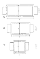
図1は、かかる組電池の一例の全体構成を示す図であり、この組電池100において、矩形板状をなす複数個の素電池10は、図示しない高分子金属複合材料製の外装フィルムで被覆されており、素電池10の集電体(図示せず)は正極又は負極タブ20を連結されている。また、タブ20はバスバー30を介して接続されており、バスバー30は、接続リード40によって、セルコントローラ53を備えた外部ケース50の外部端子51及び52に接続されている。
【0006】
【発明の実施の形態】
以下、本発明について更に詳細に説明する。
本発明は、いわゆるラミネート外装を施された素電池を備えた組電池の防振構造、耐熱構造及び内部抵抗低減構造に関するものであり、素電池に入力する外部振動による素電池の振動劣化を、タブの形状やタブ周囲の樹脂により低減し、併せて高電流使用時のタブ部発熱を防止し、更には素電池の内部抵抗の低減をさせるものである。
本発明の組電池において、素電池は2個以上設置される。組電池という限りにおいては、最小構成単位の素電池が2個以上であるためである。しかしながら、本発明をそのまま適用して、1個の素電池を特に外部振動から防振させることが可能であることは言うまでもない。
【0007】
本発明においては、素電池が高分子金属複合フィルムを外装材とし、正極及び負極のそれぞれの集電体がそれぞれ1つの正極タブ及び負極タブに連結され、これらタブが外装フィルムの封口部から素電池外に突出し、タブとの界面に高分子層が存在するが、集電体の幅とタブの幅との差がタブの幅よりも小さく、タブの断面積が、そのタブが突出する外装フィルム1辺において、タブの断面積を除いた一般溶着部断面積よりも小さいことが望ましい。
【0008】
本発明の組電池のマス(質量)バネモデルは、簡略化して考えると、図12に示すようになり、ラミネート外装の素電池本体の質量M、バネ定数K、ダンピングCと、素電池本体を構造的に外部から支えるタブ部、タブと電池本体を連結する高分子層から形成される擬似マスバネ系の質量Ma、Mbとバネ定数Ka、Kbとから成る少なくとも2自由度以上の多自由度系になると考えられる。
従来の金属缶や樹脂のケースから成る素電池ケースでは、ケース自体の剛性が高いため、それ自体でマスバネ系を形成することができなかったが、本発明では、ラミネート外装を必須条件とする素電池は、素電池全体が弾性体であるため、それ自体でマスバネ系を形成し、しかも外部と振動的に連結するタブ部のマスバネ系を直列に連結した擬似マスバネ系となる。
【0009】
かかる構成によれば、外壁がナイロン等の高分子フィルムであるため、剛体缶の電池ケースに比べて素電池の動的バネ定数が低く、振動低減に効率が高く、タブ部もタブ20の周辺を高分子層で囲うことにより(図13)、素電池全体のマスバネ系を自由に設定することが初めて可能となった。
このとき、この素電池に振動エネルギーが伝達するのをできるだけ防止するためには、組電池の共振を防ぐことが肝要である。しかしながら、共振を完全に無くすことは不可能であるため、本発明では、組電池が使用される環境下で実際に発生し得る周波数域から共振周波数をずらすことで、結果的に防振効果を大幅に向上させることが可能となった。
【0010】
上述のことから、本発明では、多自由度のマスバネ系を形成させるため、組電池を構成する素電池は、高分子金属複合フィルムを外装とする必要がある。これは素電池本体にマスバネ系を発現させるのに必要だからである。
また、正極、負極の各集電体が各別に1つの正極タブ、負極タブに連結されることが必要である。素電池のみを形成する場合は複数の正負極タブに集電体が連結されても問題ないが、複数のタブに集電体が連結されると、マスバネ系に直列と並列が混在してしまい、不均一になる可能性が高く、防振構造的に好ましくないからである。
【0011】
また、本発明において、タブは外装フィルムの封口部から素電池外に突出し、タブとの界面に高分子層が存在する必要がある。
素電池本体からタブが突出する部位は、図2のA−A’断面に示すような構造である必要がある。この理由は、タブ20と外装フィルム60の一般溶着部62には、図13に示すように、タブ20からの振動を素電池に繋ぐマスバネ系(K,C)を形成させる必要があるからである。従って、タブとの界面がマスバネ系を形成できない金属等の物質では本発明の構成を成立させることはできない。
【0012】
また、本発明では、集電体の幅Wcとタブの幅Wtとの差が当該タブの幅よりも小さいことが望ましい。
ここで、集電体11の幅Wcとは、素電池内部の正極材又は負極材の幅をいう(図2)。複数の正負の集電体12又は13は、連結部25で正極タブ又は負極タブ20に連結される(図3)。そして、集電体12又は13と連結されたタブ20が外装フィルム60から外部に突出されることになる。
このとき、素電池の質量を支えるバネの働きをするタブ部、及びタブ部の高分子層は、その面積に比例して大きくなるため、タブ部の幅Wtは可能な限り大きい方が耐振性に優れた構造になる。従って、集電体の幅とタブの幅との差がタブの幅より大きくなる(タブの幅が集電体幅の1/2よりも大きい)と、タブの幅が素電池のマスバネ系に対し小さくなるため、素電池を支えることが困難になり、防振構造として不適になることがあるからである。
【0013】
なお、本発明では、タブ20の突出部は、矩形をなす集電体11及び外装フィルム60の短辺に存在しても(図5)、長辺に存在してもよく(図7)、いずれの場合でも本発明の目的を達成可能である。
図13Aに示したのは、タブ幅が集電体幅の15%の例であり、図13Bに示したのは75%の例であるが、防振構造としては図13Bの例が適当である。
上述のように、素電池の幅とタブの幅の差がタブの幅より大きくなること(タブの幅が素電池幅の1/2よりも大きい)が電池全体の防振に関しては好ましいが、本発明は特にこれに限定されるものではない。
【0014】
更には、素電池の外装フィルムより突出したそれぞれのタブの幅が、当該外装フィルム1辺の長さの30%〜80%であることが望ましい。この範囲にあれば、タブからの振動が略均一に集電体に伝わるため、振動劣化効果が増大するためである。
また、大電流を流す場合に問題となるタブ部に発熱に対しては、タブ幅が大きい方が望ましく、素電池の内部抵抗を低減する目的のためにも望ましいが、特に限定は行わない。
【0015】
更にまた、本発明においては、タブの断面積は、当該タブが突出している外装フィルム1辺の断面において、タブの断面積を除いた一般溶着部断面積よりも小さいことが好ましい。
ここで、当該タブが突出している外装フィルム1辺における、タブの断面積を除いた一般溶着部断面積とは、図9に示すように、タブが外部に突出している辺の一般溶着部厚さAと外装フィルム幅Bとを乗算した部分の面積(A×B)をいい、幅bのタブを挟むことでタブの厚さa分だけ広がった部位の面積は含まないものである。タブの断面積(a×b)が一般溶着部断面積(A×B)よりも大きくなると、電池の質量を支える剛性は十分に確保されるが、タブのバネ定数が大きくなりすぎて、タブからの振動を直接に素電池本体に伝えやすくなるため、防振構造としては不適になることがあるからである。
従って、図10において、一般溶着部(A=250μm、B=100mm)に対し、タブ(a=550μm、b=50mm)の場合は、タブ部の断面積が一般溶着部の断面積よりも大であるため、原則として防振構造としては不適である。
また、大電流を流す場合に問題となるタブ部に発熱に対しては、タブの断面積が大きい方が望ましく、素電池の内部抵抗を低減する目的のためにも望ましいが特に限定は行わない。
【0016】
本発明においては、上述の如き防振効果に関する限定以外に、他の限定項目を加えることで、その電池固有の共振周波数を任意の周波数にシフトさせることが可能となる。即ち、本来は好ましくない素電池の1次共振周波数を高周波側にシフトさせることが可能となる(図14参照)。
例えば、車両で、この種の素電池を使用すれば、本来であれば、車両上で発現し得る周波数域で電池の共振が発現して、電池のタブ部疲労等の振動劣化が促進される可能性が高いが、この周波数シフトにより、車両上で発現し得る周波数域を超える周波数に共振周波数を移行させることが可能となり、電池の防振性能を向上させることができる。
【0017】
かかる周波数シフトの観点から、素電池の外装フィルムから突出した各タブの断面積は、これらタブが突出する外装フィルム1辺の一般溶着部断面積の5〜70%であることが望ましい。
5%未満では、バネ定数が小さくなりすぎて素電池を支える剛性が低下する可能性があり、更には高電流で使用する際にタブ部の抵抗が高くなることに起因してタブの温度が極端に上昇する可能性があるからである。また、70%を超えると、バネ定数が高くなり、周波数のシフトを大きくできないからである。
【0018】
上記同様の観点から、素電池の外装フィルムより突出した各タブの厚さは、外装フィルム1辺の一般溶着部厚さの20〜80%であることが望ましい。
20%未満の場合は、タブの剛性が小さくなり、電池本体を支えることが困難になる可能性が高く、80%を超えると、バネ定数が高くなり、周波数のシフトを大きくできないからである。
【0019】
また、本発明では、素電池の外装フィルムより突出した各タブは、外装フィルムのそれぞれ異なった1辺から突出していることが望ましい。
一般のラミネート外装電池は、セルの1側面に正極及び負極のタブを有する形状である。しかしながら、この形状のセルを組電池内に設置するときには、タブ部をリード線等に結合する点で、タブ部の接続バネ定数がどうしても大きくなり、組電池の内部で固定端となる。これに振動が入力すると、タブの無い自由端の揺れが大きくなり、タブ部の金属疲労が置き易い可能性があった。これは本発明の性能劣化防止の目的に反する可能性がある。
これに対し、セルの両端にタブ端子を有する素電池では、両側のタブをモジュール内に設置したとき、振動が均一に入力するため、タブ部の金属疲労が起きにくくなるからである。
なお、タブが突出する辺において、タブ20の中央部が素電池10の中央部と合致していなくても(図6及び図8)、本発明の目的は達成できるが、タブ幅の中心と電池幅の中心が略重なった態様の方(図5及び図7)が防振構造上好ましい。
【0020】
また、素電池の最大厚さは1〜10mmであることが望ましい。素電池本体のバネ定数は、その電池全体のヤング率によって定まるが、素電池の厚さがあまりに大きいとバネ定数が小さくなり、周波数をシフトさせることが困難になるからである。更に10mmを超えると、素電池の内部に熱がこもり易くなり熱劣化にも大きくなる可能性が高くなるからである。
一方、1mm未満では、素電池のバネ定数が極めて高くなり、加圧力とのバランス等についての問題が大きい。更に、厚さ1mm未満の電池は、正極、負極の層を薄くしても容量が稼げないため、経済的に効率が高いとは言えない。
【0021】
更に、矩形板状をなす素電池では、2辺の長さの比が1:1〜1:3であることが望ましい。
効果的に防振効果を得るためには、素電池の2辺の比が1:1(図11A)に近い方が望ましく、それから外れて行くと電池本体のねじれが大きくなって行く。2辺の比が1:3(図11C)より大きいと、電池が長くなりすぎて振動入力に対して電池の中央部の振幅が大きくなってタブ部の負担が大きくなり、問題になる可能性が大きいからである。但し、1:1の場合は容量が小さくなるため、大容量の組電池を得るのに素電池数を増加させなければならず、経済的に好ましくない可能性がある。従って、実際上は1:2(図11B)に近い方が最適であるが、特に限定は行わない。
【0022】
次に、素電池やタブなどの材質について説明する。
本発明において、素電池の正極及び負極それぞれのタブは、ニッケル(Ni)、銅(Cu)、アルミニウム(Al)又は鉄(Fe)及びこれらの任意の組合せから選ばれることが望ましい。
これらの素材は、タブ程度の厚さ(50〜300μm)の範囲に形成した際に剛性が電池の自重を支える上で適当であるため、周波数シフトが容易に実現可能であるからでる。
また、外装フィルムの融着部の材質は、ポリプロピレン(PP)、変性PP、ポリエチレン(PE)、変性PE又はアイオノマー及びこれらの任意の組合せから選ばれることが望ましい。
これらの高分子材料は、上述したタブ金属との連結部でバネを形成するが、そのバネ定数が電池のバネ定数に比較的近いため、周波数シフトが容易であるからである。
【0023】
更に、素電池の正極材としてはリチウム(Li)−マンガン(Mn)系複合酸化物が望ましく、負極材としては結晶性及び/又は非結晶性の炭素材が望ましい。
これらは、電池の連結部に対してバネ定数が十分に大きい素材であるため、素電池のマスバネ系を形成する際に電池の内部を揺らす可能性が小さく、電池本体の振動劣化を低減させることが可能となる。また、これに対しタブ部は振動が伝わり易くなる可能性があるが、周波数シフトにより、実際に共振点を移行させることが可能となるため、防振構造的には問題は無い。
【0024】
本発明の組電池の好適態様としては、上述のような素電池を2つ以上並列に接続したグループが少なくとも1個存在し、その並列の接続形式が、電池を積層し、その積層枚数と同数の正極及び負極タブをそれぞれ溶着した形式のものを挙げることができる。
図16(A)に示す通り、並列結合では正極同士、負極同士を接続するため、外部からの振動侵入に対し、同位相で応力がかかるため、ねじり力によって素電池が劣化する可能性が小さい。一方、直列接続(図16(B))では、正極−負極の連結が必ず存在するため、ねじり力が電池にかかり易いからである。
【0025】
また、本発明の組電池の他の好適態様としては、上述のような素電池を少なくとも2つ並列に接続したグループが少なくとも1個存在し、その並列の接続形式が、電池を辺方向に並列させ、複数の正極タブ12及び負極タブ13をそれぞれ1枚のバスバー32,33に溶着させた形式であるものを挙げることができる。
図15(A)に示す通り、並列結合では正極同士、負極同士を接続するため、外部からの振動侵入に対して同位相で応力がかかるため、ねじり力により素電池が劣化する可能性が小さい。一方、直列接続(図15(B))は正極−負極の連結が必ず存在するため、ねじり力が電池に加わり易いからである。
なお、これらの連結構造については、組電池中の素電池の連結が全て並列になることが最も望ましいが、少なくとも1個所あれば本発明の効果を奏する。
【0026】
本発明の組電池を2つ以上直列、並列又は直列と並列との複合接続することにより、複合組電池を形成することは極めて有効である(図20参照)。
使用目的に適当な容量、電圧を組電池の組み合わせにより形成することが可能となるからである。素電池のままで適当な容量等を形成することも可能であるが、接続数が極端に増えることにより、1つのセル(素電池)の劣化により組電池全体が劣化してしまう可能性が高くなり、且つセル数が多くなることにより、マス(質量)が増え、振動低減が困難になるからである。
従って、ある適当な個数の素電池により組電池を形成した後、その組電池を複数結合することにより、最終的な複合組電池とすることが望ましいことになる。
なお、図20は、図18に示した組電池を6並列にして形成した複合組電池を示している。
【0027】
本発明の組電池、複合組電池を自動車用に適用することは極めて有効である(図21参照)。
自動車に使用する場合に重要なことは、自動車に発生する振動周波数の周波数範囲内から組電池の共振周波数をはずすことである。他自由度のマスバネ系では共振周波数を無くすことは不可能であるが、自動車上で発生しうる周波数範囲内から、本発明の組電池の共振周波数を外すことは可能である。これにより、車上で使用する限り、組電池は共振周波数に達しないという効果が得られる。
特に、組電池に必要な防振周波数は、10〜100Hzの範囲であり、10Hz未満の周波数領域では、組電池サイズ的観点からも共振周波数は存在する可能性が低い。また1kHzを超える周波数は、音の領域に入るため、防振の必要性も低くなる。
【0028】
【実施例】
以下、本発明を実施例によって更に詳細に説明するが、本発明はこれらによって限定されるものではない。
【0029】
(実施例1)
金属製の外部ケースに、高分子金属複合フィルム外装の素電池(図5B参照、厚さ4mm、正極タブAl、負極タブNi、タブと一般シール部断面積の比=28%、タブと一般シール部厚さの比=60%、タブと外装フィルム幅の比=47%、タブとの界面の樹脂PP、縦横比=1:2)を図17Aに示す連結状態で4並列接続し、組電池1を作成した。
また、この組電池1を後述するハンマリング試験に供し、外部ケースの固有振動スペクトルを測定したところ、基準構造に対し、共振1次ピーク周波数は約125Hz高周波側に移行した。また、加速度比を10〜300Hzで測定し、その低減量の平均を測定したところ、その低減量は3dBであった。
【0030】
(実施例2)
素電池のスペックを(図5B参照、厚さ4mm、正極タブAl、負極タブNi、タブと一般シール部断面積の比=9%、タブと一般シール部厚さの比=20%、タブと外装フィルム幅の比=47%、タブとの界面の樹脂PP、縦横比=1:2)とした以外は、実施例1と全く同様の構成を採用して組電池2を製造した。また、この組電池2の共振1次ピーク周波数差は約200Hzであり、その平均低減量は5dBであった。
【0031】
(実施例3)
素電池のスペックを(図5A、厚さ4mm、正極タブAl、負極タブNi、タブと一般シール部断面積の比=47%、タブと一般シール部厚さの比=60%、タブと外装フィルム幅の比=79%、タブとの界面の樹脂を変性PP、縦横比=1:2)とした以外は、実施例1と全く同様の構成を採用して組電池3を製造した。また、この組電池3の共振1次ピーク周波数差は約100Hzであり、その平均低減量は2dBであった。
【0032】
(実施例4)
素電池のスペックを(図5C、厚さ4mm、正極タブAl、負極タブNi、タブと一般シール部断面積の比=25%、タブと一般シール部厚さの比=60%、タブと外装フィルム幅の比=42%、タブとの界面の樹脂PE、縦横比=1:2)とした以外は、実施例1と全く同様の構成を採用して組電池4を製造した。また、この組電池4の共振1次ピーク周波数差は約175Hzであり、その平均低減量は3dBであった。
【0033】
(実施例5)
素電池のスペックを(図5B、厚さ4mm、正極タブAl、負極タブNi、タブと一般シール部断面積の比=67%、タブと一般シール部厚さの比=80%、タブと外装フィルム幅の比=84%、タブとの界面の樹脂を変性PE、縦横比=1:2)とした以外は、実施例1と全く同様の構成を採用して組電池5を製造した。また、この組電池5の共振1次ピーク周波数差は約75Hzであり、その平均低減量は1dBであった。
【0034】
(実施例6)
素電池のスペックを(図6A、厚さ8mm、正極タブAl、負極タブCu、タブと一般シール部断面積の比=28%、タブと一般シール部厚さの比=60%、タブと外装フィルム幅の比=47%、タブとの界面の樹脂をアイオノマー、縦横比=1:2)とした以外は、実施例1と全く同様の構成を採用して組電池6を製造した。また、この組電池6の共振1次ピーク周波数差は約105Hzであり、その平均低減量は3.5dBであった。
【0035】
(実施例7)
素電池のスペックを(図6B、厚さ8mm、正極タブAl、負極タブFe、タブと一般シール部断面積の比=28%、タブと一般シール部厚さの比=60%、タブと外装フィルム幅の比=47%、タブとの界面の樹脂をアイオノマー、縦横比=1:2)とした以外は、実施例1と全く同様の構成を採用して組電池7を製造した。また、この組電池7の共振1次ピーク周波数差は約100Hzであり、その平均低減量は3dBであった。
【0036】
(実施例8)
素電池のスペックを(図7A、厚さ4mm、正極タブAl、負極タブNi、タブと一般シール部断面積の比=53%、タブと一般シール部厚さの比=60%、タブと外装フィルム幅の比=88%、タブとの界面の樹脂をPP、縦横比=1:2)とした以外は、実施例1と全く同様の構成を採用して組電池8を製造した。また、この組電池8の共振1次ピーク周波数差は約100Hzであり、その平均低減量は1.5dBであった。
【0037】
(実施例9)
素電池のスペックを(図7B、厚さ4mm、正極タブAl、負極タブNi、タブと一般シール部断面積の比=26%、タブと一般シール部厚さの比=60%、タブと外装フィルム幅の比=44%、タブとの界面の樹脂をPP、縦横比=1:2)とした以外は、実施例1と全く同様にして組電池9を製造した。
また、この組電池9の共振1次ピーク周波数差は約125Hzであり、その平均低減量は3dBであった。
【0038】
(実施例10)
素電池のスペックを(図8A、厚さ2mm、正極タブAl、負極タブNi、タブと一般シール部断面積の比=26%、タブと一般シール部厚さの比=60%、タブと外装フィルム幅の比=44%、タブとの界面の樹脂をPP、縦横比=1:2)とした以外は、実施例1と全く同様の構成を採用して組電池10を製造した。また、この組電池10の共振1次ピーク周波数差は約175Hzであり、その平均低減量は2.5dBであった。
【0039】
(実施例11)
素電池のスペックを(図8B、厚さ2mm、正極タブAl、負極タブNi、タブと一般シール部断面積の比=26%、タブと一般シール部厚さの比=60%、タブと外装フィルム幅の比=44%、タブとの界面の樹脂をPP、縦横比=1:2)とした以外は、実施例1と全く同様の構成を採用して組電池11を製造した。また、この組電池11の共振1次ピーク周波数差は約175Hzであり、その平均低減量は3dBであった。
【0040】
(実施例12)
素電池のスペックを(図11A、厚さ4mm、正極タブAl、負極タブNi、タブと一般シール部断面積の比=28%、タブと一般シール部厚さの比=60%、タブと外装フィルム幅の比=47%、タブとの界面の樹脂をPP、縦横比=1:1)とした以外は、実施例1と全く同様の構成を採用して組電池12を製造した。また、この組電池12の共振1次ピーク周波数差は約110Hzであり、その平均低減量は2.5dBであった。
【0041】
(実施例13)
素電池のスペックを(図11C、厚さ4mm、正極タブAl、負極タブNi、タブと一般シール部断面積の比=28%、タブと一般シール部厚さの比=60%、タブと外装フィルム幅の比=47%、タブとの界面の樹脂をPP、縦横比=1:3)とした以外は、実施例1と全く同様の構成を採用して組電池13を製造した。また、この組電池13の共振1次ピーク周波数差は約90Hzであり、その平均低減量は3.5dBであった。
【0042】
(実施例14)
素電池のスペックを(図5B、厚さ4mm、正極タブAl、負極タブNi、タブと一般シール部断面積の比=28%、タブと一般シール部厚さの比=60%、タブと外装フィルム幅の比=47%、タブとの界面の樹脂をPP、縦横比=1:2)とし、連結状態図15Bで4並列接続した以外は、実施例1と全く同様の構成を採用して組電池14を製造した。また、この組電池14の共振1次ピーク周波数差は約100Hzであり、その平均低減量は3dBであった。
【0043】
(実施例15)
素電池のスペックを(図5B、厚さ4mm、正極タブAl、負極タブNi、タブと一般シール部断面積の比=28%、タブと一般シール部厚さの比=60%、タブと外装フィルム幅の比=47%、タブとの界面の樹脂をPP、縦横比=1:2)とし、連結状態図1で2並12直列接続した以外は、実施例1と全く同様の構成を採用して組電池15を製造した。また、この組電池15の共振1次ピーク周波数差は約120Hzであり、その平均低減量は4dBであった。
【0044】
(比較例1)
素電池のスペックを(図5B、厚さ4mm、正極タブAl、負極タブNi、タブと一般シール部断面積の比=6%、タブと一般シール部厚さの比=60%、タブと外装フィルム幅の比=11%、タブとの界面の樹脂をPP、縦横比=1:2)とした以外は、実施例1と全く同様の構成を採用して組電池を製造した。
また、この組電池の共振1次ピーク周波数差は見られず、その平均低減量は0dBであった。
【0045】
(比較例2)
素電池のスペックを(図5B、厚さ4mm、正極タブAl、負極タブNi、タブと一般シール部断面積の比=105%、タブと一般シール部厚さの比=200%、タブと外装フィルム幅の比=53%、タブとの界面の樹脂をPP、縦横比=1:2)とした以外は、実施例1と全く同様の構成を採用して組電池を製造した。また、この組電池の共振1次ピーク周波数差は見られず、その平均低減量は−0.5dBであった。
【0046】
(比較例3)
素電池のスペックを(図5B、厚さ4mm、正極タブAl、負極タブNi、タブと一般シール部断面積の比=28%、タブと一般シール部厚さの比=60%、タブと外装フィルム幅の比=47%、タブとの界面の樹脂の樹脂無し、縦横比=1:2)とした以外は、実施例1と全く同様の構成を採用して組電池を製造した。また、この組電池の共振1次ピーク周波数差は見られず、その平均低減量は−0.5dBであった。
【0047】
(参考例)
素電池のスペックを(図18、厚さ4mm、正極タブAl、負極タブNi、タブと一般シール部断面積の比=6%、タブと一般シール部厚さの比=60%、タブと外装フィルム幅の比=11%、タブとの界面の樹脂PP、縦横比=1:2)とし、連結構造を図17Bとして4並列結合をした以外は、実施例1と全く同様の構成を採用して組電池を製造した。
【0048】
(試験例)
上記実施例1〜15、比較例1及び2、並びに参考例で得られた組電池について、以下の試験を実施した。得られた結果は各例の組電池のスペックとともに表1に示す。
【0049】
1.ハンマリング試験
上記の各実施例等の組電池の外部ケースの略中央部に加速度ピックアップを設定し、インパルスハンマーによって外部ケースの一部をハンマリングしたときの加速度ピックアップの振動スペクトルを測定した。設定方法はJIS B0908(振動及び衝撃ピックアップの公正方法・基本概念)に準拠した。
測定スペクトルはFFT分析器により解析し、周波数と加速度の次元に変換し、共振スペクトルを得た。得られた共振スペクトルで最も低周波側に出現するものを1次共振周波数とした。
また、1次共振周波数差は、参考例の組電池の1次共振周波数と、それぞれの実施例の組電池の1次共振周波数との差と定義した。実施例14、15についても外部ケースは同様のものを使用し、素電池だけ参考例の仕様を用いた組電池を基準とした。
【0050】
2.平均低減率の測定
ハンマリング試験より得られたスペクトルより、その加速度を10−300Hzで平均し、基準の組電池の場合の低減量を引いて算出した。その数値が大きいほど、本発明の構成によって、振動が低減されたことを意味する。
【0051】
【表1】

表1の結果から明らかなように、本発明の範囲に属する実施例1〜15では、各因子の操作により1次共振周波数を基準仕様に対して高周波数域にシフトさせることが可能であり、また振動伝達が低減されることで車両から発生する振動との共振を防止してタブ部への負荷を低減できることが分かる。
これに対し、本発明範囲外の仕様である比較例はそのような効果を得られる結果とはならなかった。
【0053】
【発明の効果】
以上説明したように、本発明の組電池によれば、従来の構造では達成し得なかった防振性能が実現され、更には、内部抵抗の低減や熱性能の向上を両立させることが可能となった。
【図面の簡単な説明】
【図1】本発明の組電池の一例を示す模式図である。
【図2】素電池の構造を示す正面及び側面図である。
【図3】素電池構造を示す上面及び断面図である。
【図4】素電池構造を示す上面及び断面図である。
【図5】素電池構造を示す模式図である。
【図6】素電池構造の模式図である。
【図7】素電池構造の模式図である。
【図8】素電池構造の模式図である。
【図9】素電池の断面構造を示す模式図である。
【図10】素電池の断面構造を示す模式図である。
【図11】素電池構造の模式図である。
【図12】マス−バネモデルの模式図である。
【図13】マス−バネモデルの模式図である。
【図14】振動伝達率比較図である。
【図15】素電池連結構造の模式図である。
【図16】素電池連結構造の模式図である。
【図17】素電池連結構造の模式図である。
【図18】素電池構造の模式図である。
【図19】組電池構造の一例を示す斜視図である。
【図20】複合組電池の一例を示す斜視図である。
【図21】複合組電池を搭載した車両の一例を示す模式図である。
【符号の説明】
10 素電池
11 集電体
20 タブ
25 連結部
30 バスバー
40 接続リード
50 外部ケース
51,52 外部端子
53 セルコントローラ
60 外装フィルム
62 一般溶着部
100 組電池
Wt タブ幅
Wc 集電体幅[0001]
BACKGROUND OF THE INVENTION
The present invention relates to an assembled battery performance deterioration prevention and vibration-proof structure, and in particular, by defining the structure of the tab portion of the unit cell constituting the assembled battery, mainly reducing vibrations input from the outside, Furthermore, the present invention relates to an assembled battery with reduced thermal performance and internal resistance, a composite assembled battery using the same, and a vehicle.
[0002]
[Prior art]
A parallel or series assembled battery in which a plurality of unit cells are connected is used in an environment where vibration is input, so that the terminal part or bus bar which is the connection part of the battery is fatigued by the vibration and the resistance increases. It could lead to fatigue failure. In order to solve these problems, conventionally, a structure in which batteries are connected to each other through rubber is formed to reduce the vibration (Japanese Patent Laid-Open No. 11-273634).
[0003]
[Problems to be solved by the invention]
However, in such a conventional structure, since the rubber cushioning members are disposed only at the connecting portions on both sides of the cylindrical can forming the unit cell, natural vibrations such as primary and secondary in the length direction of the cylindrical can are obtained. In terms of frequency, the amplitude was large at the center portion or 1/4 or 3/4 wavelength portion of the cylindrical can, and it was easy to cause fatigue on the side surface of the cylindrical can. Further, since the stress is directly applied to the buffer members on both sides of the cylindrical can, the durability of the buffer member often becomes a problem.
In addition, in a unit cell using a polymer-metal composite laminate such as a laminate material as an exterior material, it is difficult to fix it through a buffer member because the battery itself is not rigid. If used below, the terminals and bus bars, which are battery-to-battery connections, may become fatigued by the vibrations, leading to increased resistance and fatigue failure.
[0004]
The present invention has been made in view of such problems of the prior art, and can achieve both the vibration-proofing effect and the performance deterioration prevention that could not be achieved by the conventional structure. It aims at providing the assembled battery which can suppress an increase, a composite assembled battery, and a vehicle.
[0005]
[Means for Solving the Problems]
The purpose of the present invention is to provide an assembled battery having at least two unit cells, in which the unit cell has a polymer metal composite film as an exterior, and the current collectors of the positive electrode and the negative electrode are connected to one positive electrode tab and a negative electrode tab, respectively. The battery assembly of the present invention is characterized in that it protrudes from the sealing portion of the polymer metal composite exterior film to the outside of the unit cell and a polymer layer exists at the interface with the tab.
FIG. 1 is a diagram showing an overall configuration of an example of such an assembled battery. In this assembled
[0006]
DETAILED DESCRIPTION OF THE INVENTION
Hereinafter, the present invention will be described in more detail.
The present invention relates to an anti-vibration structure, a heat-resistant structure and an internal resistance reduction structure of an assembled battery including a unit cell with a so-called laminate exterior, and vibration deterioration of the unit cell due to external vibration input to the unit cell. It is reduced by the shape of the tab and the resin around the tab, and at the same time, heat generation of the tab portion when using a high current is prevented, and further, the internal resistance of the unit cell is reduced.
In the assembled battery of the present invention, two or more unit cells are installed. This is because the number of unit cells of the minimum structural unit is two or more as long as it is an assembled battery. However, it is needless to say that the present invention can be applied as it is, and one unit cell can be particularly prevented from external vibration.
[0007]
In the present invention, the unit cell uses a polymer metal composite film as an exterior material, and the current collectors of the positive electrode and the negative electrode are connected to one positive electrode tab and a negative electrode tab, respectively. Projects out of the battery, and there is a polymer layer at the interface with the tab, but the difference between the current collector width and the tab width is smaller than the tab width, and the cross-sectional area of the tab projects the tab It is desirable that one side of the film be smaller than the cross-sectional area of the general welded portion excluding the cross-sectional area of the tab.
[0008]
When considered in a simplified manner, the mass (mass) spring model of the assembled battery of the present invention is as shown in FIG. 12, and the mass M, the spring constant K, the damping C, and the unit cell body of the laminated exterior are structured. A multi-degree-of-freedom system having at least two degrees of freedom consisting of a mass portion Ma, Mb and a spring constant Ka, Kb of a pseudo mass spring system formed of a tab portion supported externally, and a polymer layer connecting the tab and the battery body. It is considered to be.
In a conventional battery case made of a metal can or a resin case, the case itself cannot be formed because the case itself has high rigidity. However, in the present invention, an element that requires a laminate exterior is essential. Since the entire unit cell is an elastic body, the battery forms a mass spring system by itself, and becomes a pseudo mass spring system in which the mass spring systems of the tab portions that are vibrationally connected to the outside are connected in series.
[0009]
According to such a configuration, since the outer wall is a polymer film such as nylon, the dynamic spring constant of the unit cell is lower than that of the battery case of the rigid can, the vibration is highly efficient, and the tab portion is also around the
At this time, in order to prevent vibration energy from being transmitted to the unit cell as much as possible, it is important to prevent resonance of the assembled battery. However, since it is impossible to completely eliminate the resonance, the present invention shifts the resonance frequency from the frequency range that can actually occur in the environment where the assembled battery is used, resulting in a vibration isolation effect. It became possible to greatly improve.
[0010]
From the above, in the present invention, in order to form a mass spring system with multiple degrees of freedom, the unit cell constituting the assembled battery needs to have a polymer metal composite film as an exterior. This is because it is necessary to develop a mass spring system in the unit cell body.
Further, it is necessary that each of the current collectors of the positive electrode and the negative electrode is connected to one positive electrode tab and one negative electrode tab. In the case of forming only unit cells, there is no problem even if the current collector is connected to a plurality of positive and negative electrode tabs. However, if the current collector is connected to a plurality of tabs, the mass spring system is mixed in series and parallel. This is because the possibility of non-uniformity is high and this is not preferable in terms of the vibration-proof structure.
[0011]
Moreover, in this invention, a tab protrudes out of a unit cell from the sealing part of an exterior film, and a polymer layer needs to exist in an interface with a tab.
The portion where the tab protrudes from the unit cell body needs to have a structure as shown in the AA ′ cross section of FIG. This is because it is necessary to form a mass spring system (K, C) for connecting the vibration from the
[0012]
In the present invention, it is desirable that the difference between the current collector width Wc and the tab width Wt is smaller than the width of the tab.
Here, the width Wc of the
At this time, the tab portion that acts as a spring that supports the mass of the unit cell and the polymer layer of the tab portion increase in proportion to the area thereof, so that the tab portion width Wt should be as large as possible for vibration resistance. Excellent structure. Therefore, when the difference between the width of the current collector and the width of the tab is larger than the width of the tab (the width of the tab is larger than half the width of the current collector), the width of the tab becomes the mass spring system of the unit cell. On the other hand, since it becomes small, it becomes difficult to support a unit cell, and it may become unsuitable as an anti-vibration structure.
[0013]
In the present invention, the protruding portion of the
FIG. 13A shows an example in which the tab width is 15% of the current collector width, and FIG. 13B shows an example in which 75%, but the example of FIG. is there.
As described above, it is preferable for the vibration isolation of the entire battery that the difference between the width of the unit cell and the width of the tab is larger than the width of the tab (the width of the tab is larger than ½ of the unit cell width). The present invention is not particularly limited to this.
[0014]
Furthermore, it is desirable that the width of each tab protruding from the outer film of the unit cell is 30% to 80% of the length of one side of the outer film. If it is within this range, the vibration from the tab is transmitted almost uniformly to the current collector, so that the vibration deterioration effect is increased.
Further, with respect to heat generation in the tab portion which causes a problem when a large current is passed, it is desirable that the tab width is large, and it is also desirable for the purpose of reducing the internal resistance of the unit cell, but there is no particular limitation.
[0015]
Furthermore, in the present invention, the cross-sectional area of the tab is preferably smaller than the cross-sectional area of the general welded portion excluding the cross-sectional area of the tab in the cross section of one side of the exterior film from which the tab protrudes.
Here, the general welded portion cross-sectional area excluding the cross-sectional area of the tab on one side of the exterior film from which the tab protrudes is the thickness of the general welded portion of the side where the tab protrudes to the outside as shown in FIG. The area (A × B) of the portion obtained by multiplying the thickness A by the exterior film width B is included, and does not include the area of the portion widened by the thickness a of the tab by sandwiching the tab of width b. If the tab cross-sectional area (a × b) is larger than the general weld cross-sectional area (A × B), sufficient rigidity to support the mass of the battery is secured, but the tab spring constant becomes too large, and the tab This is because it is easy to transmit the vibration from the cell unit directly to the unit cell body, which may be unsuitable as an anti-vibration structure.
Therefore, in FIG. 10, in the case of a tab (a = 550 μm, b = 50 mm) with respect to the general welded portion (A = 250 μm, B = 100 mm), the cross-sectional area of the tab portion is larger than the cross-sectional area of the general welded portion. Therefore, in principle, it is not suitable as a vibration-proof structure.
In addition, it is desirable that the tab has a large cross-sectional area for heat generation in the tab portion, which is a problem when a large current is passed, and it is desirable for the purpose of reducing the internal resistance of the unit cell, but is not particularly limited. .
[0016]
In the present invention, it is possible to shift the resonance frequency unique to the battery to an arbitrary frequency by adding other limitation items in addition to the above-described limitation regarding the vibration isolation effect. That is, it is possible to shift the primary resonance frequency of the originally undesirable cell to the high frequency side (see FIG. 14).
For example, if this type of unit cell is used in a vehicle, resonance of the battery appears in a frequency range that can be expressed on the vehicle, and vibration deterioration such as fatigue of the tab portion of the battery is promoted. Although the possibility is high, this frequency shift makes it possible to shift the resonance frequency to a frequency that exceeds the frequency range that can be expressed on the vehicle, and to improve the anti-vibration performance of the battery.
[0017]
From the viewpoint of such a frequency shift, the cross-sectional area of each tab protruding from the outer film of the unit cell is preferably 5 to 70% of the cross-sectional area of the general welded portion on one side of the outer film from which these tabs protrude.
If it is less than 5%, the spring constant may be too small and the rigidity to support the unit cell may be lowered. Further, the tab temperature may be increased due to the increased resistance of the tab portion when used at a high current. This is because it may rise extremely. On the other hand, if it exceeds 70%, the spring constant increases and the frequency shift cannot be increased.
[0018]
From the same viewpoint as described above, the thickness of each tab protruding from the outer film of the unit cell is desirably 20 to 80% of the thickness of the general welded portion on one side of the outer film.
If it is less than 20%, the rigidity of the tab becomes small, and it is likely that it is difficult to support the battery body. If it exceeds 80%, the spring constant becomes high and the frequency shift cannot be increased.
[0019]
Moreover, in this invention, it is desirable for each tab which protruded from the exterior film of the unit cell to protrude from one different side of the exterior film.
A general laminated battery has a shape having positive and negative electrode tabs on one side of a cell. However, when the cell having this shape is installed in the assembled battery, the connection spring constant of the tab portion is inevitably increased in that the tab portion is coupled to a lead wire or the like, and becomes a fixed end inside the assembled battery. When vibration is input to this, the shaking of the free end without the tab becomes large, and there is a possibility that the metal fatigue of the tab portion is easy to put. This may be contrary to the purpose of the present invention for preventing performance degradation.
On the other hand, in a unit cell having tab terminals at both ends of the cell, when tabs on both sides are installed in the module, vibrations are input uniformly, so that metal fatigue of the tab portion is less likely to occur.
Even if the center of the
[0020]
The maximum thickness of the unit cell is preferably 1 to 10 mm. This is because the spring constant of the unit cell body is determined by the Young's modulus of the entire cell, but if the unit cell thickness is too large, the spring constant decreases and it is difficult to shift the frequency. Further, if it exceeds 10 mm, heat tends to be trapped inside the unit cell, and the possibility of increasing thermal deterioration increases.
On the other hand, if it is less than 1 mm, the spring constant of the unit cell becomes extremely high, and there is a large problem with respect to the balance with the applied pressure. Furthermore, a battery having a thickness of less than 1 mm cannot be said to be economically efficient because the capacity cannot be obtained even if the positive electrode and negative electrode layers are thinned.
[0021]
Furthermore, in the unit cell having a rectangular plate shape, the ratio of the lengths of the two sides is preferably 1: 1 to 1: 3.
In order to effectively obtain an anti-vibration effect, it is desirable that the ratio of the two sides of the unit cell is close to 1: 1 (FIG. 11A). If the ratio of the two sides is larger than 1: 3 (FIG. 11C), the battery becomes too long, the amplitude of the central part of the battery with respect to the vibration input becomes large, and the burden on the tab part increases, which may cause a problem. Because is big. However, since the capacity becomes small in the case of 1: 1, the number of unit cells must be increased in order to obtain a large capacity assembled battery, which may be economically undesirable. Therefore, in practice, the ratio closer to 1: 2 (FIG. 11B) is optimal, but no particular limitation is made.
[0022]
Next, materials such as unit cells and tabs will be described.
In the present invention, the positive and negative electrode tabs of the unit cell are preferably selected from nickel (Ni), copper (Cu), aluminum (Al), iron (Fe), and any combination thereof.
This is because these materials are suitable for supporting the self-weight of the battery when formed in a thickness range of about a tab (50 to 300 μm), and therefore a frequency shift can be easily realized.
Moreover, it is desirable that the material of the fused portion of the exterior film is selected from polypropylene (PP), modified PP, polyethylene (PE), modified PE, ionomer, and any combination thereof.
These polymer materials form a spring at the connecting portion with the above-described tab metal, because the spring constant is relatively close to the spring constant of the battery, so that the frequency shift is easy.
[0023]
Furthermore, lithium (Li) -manganese (Mn) based composite oxide is desirable as the positive electrode material of the unit cell, and crystalline and / or amorphous carbon material is desirable as the negative electrode material.
Since these are materials having a sufficiently large spring constant with respect to the battery connection part, there is little possibility of shaking the inside of the battery when forming the mass spring system of the unit cell, and the vibration deterioration of the battery body is reduced. Is possible. On the other hand, there is a possibility that vibration is easily transmitted to the tab portion. However, since the resonance point can be actually shifted by the frequency shift, there is no problem in terms of the vibration isolation structure.
[0024]
As a preferred embodiment of the assembled battery of the present invention, there is at least one group in which two or more unit cells as described above are connected in parallel, and the parallel connection type is the same as the number of stacked layers. The positive electrode and the negative electrode tab may be welded.
As shown in FIG. 16 (A), since the positive and negative electrodes are connected in parallel connection, stress is applied in the same phase with respect to vibration intrusion from the outside, so that the possibility of deterioration of the unit cell due to torsional force is small. . On the other hand, in series connection (FIG. 16B), there is always a positive / negative electrode connection, so that a twisting force is easily applied to the battery.
[0025]
Further, as another preferred embodiment of the assembled battery of the present invention, there is at least one group in which at least two unit cells as described above are connected in parallel, and the parallel connection type is parallel to the battery in the side direction. And a plurality of
As shown in FIG. 15 (A), since the positive and negative electrodes are connected in parallel connection, stress is applied in the same phase against external vibration intrusion, so the possibility that the unit cell is deteriorated by torsional force is small. . On the other hand, in the series connection (FIG. 15B), there is always a positive / negative electrode connection, so that a torsional force is easily applied to the battery.
In addition, as for these connection structures, it is most desirable that all the unit cells in the assembled battery are connected in parallel, but the effect of the present invention can be obtained if there is at least one.
[0026]
It is extremely effective to form a composite battery pack by connecting two or more battery packs of the present invention in series, in parallel, or in series and in parallel (see FIG. 20).
This is because a capacity and voltage suitable for the purpose of use can be formed by a combination of assembled batteries. Although it is possible to form an appropriate capacity or the like with the unit cell as it is, there is a high possibility that the entire assembled battery will deteriorate due to deterioration of one cell (unit cell) due to the extremely increased number of connections. This is because, when the number of cells increases, the mass increases, and it becomes difficult to reduce vibration.
Accordingly, it is desirable to form an assembled battery from a certain appropriate number of unit cells, and then combine a plurality of the assembled batteries to form a final composite assembled battery.
In addition, FIG. Is FIG. 6 shows a composite assembled battery formed by arranging 6 assembled batteries in parallel.
[0027]
It is extremely effective to apply the assembled battery and composite assembled battery of the present invention to automobiles (see FIG. 21).
When used in an automobile, it is important to remove the resonance frequency of the assembled battery from the frequency range of the vibration frequency generated in the automobile. Although it is impossible to eliminate the resonance frequency in a mass spring system having other degrees of freedom, it is possible to remove the resonance frequency of the assembled battery of the present invention from the frequency range that can be generated on an automobile. Thereby, as long as it uses on a vehicle, the effect that an assembled battery does not reach a resonant frequency is acquired.
In particular, the vibration proof frequency necessary for the assembled battery is in the range of 10 to 100 Hz, and in the frequency region below 10 Hz, there is a low possibility that the resonance frequency exists from the viewpoint of the assembled battery size. Further, since the frequency exceeding 1 kHz falls within the sound region, the necessity for vibration isolation is reduced.
[0028]
【Example】
EXAMPLES Hereinafter, although an Example demonstrates this invention further in detail, this invention is not limited by these.
[0029]
(Example 1)
Unit cell of polymer metal composite film exterior on metal outer case (see FIG. 5B, thickness 4 mm, positive electrode tab Al, negative electrode tab Ni, ratio of tab and general seal section cross section = 28%, tab and general seal The thickness ratio of the part = 60%, the ratio of the tab to the outer film width = 47%, the resin PP at the interface with the tab, and the aspect ratio = 1: 2) were connected in parallel in the connected state shown in FIG. 1 was created.
Moreover, when this assembled
[0030]
(Example 2)
The specifications of the unit cell (see FIG. 5B, thickness 4 mm, positive electrode tab Al, negative electrode tab Ni, tab to general seal part cross-sectional area ratio = 9%, tab to general seal part thickness ratio = 20%, tab and The assembled
[0031]
(Example 3)
The specifications of the unit cell (FIG. 5A, thickness 4 mm, positive electrode tab Al, negative electrode tab Ni, ratio of tab and general seal part cross-sectional area = 47%, ratio of tab and general seal part thickness = 60%, tab and exterior
[0032]
(Example 4)
The specifications of the unit cell (FIG. 5C, thickness 4 mm, positive electrode tab Al, negative electrode tab Ni, ratio of the cross-sectional area of the tab and the general seal portion = 25%, ratio of the tab and the thickness of the general seal portion = 60%, the tab and the exterior A battery pack 4 was manufactured by adopting the same configuration as in Example 1 except that the film width ratio was 42%, the resin PE at the interface with the tab, and the aspect ratio = 1: 2. Moreover, the resonance primary peak frequency difference of this assembled battery 4 was about 175 Hz, and the average reduction amount was 3 dB.
[0033]
(Example 5)
The specifications of the unit cell (FIG. 5B, thickness 4 mm, positive electrode tab Al, negative electrode tab Ni, cross-sectional area ratio of tab and general seal part = 67%, ratio of tab and general seal part thickness = 80%, tab and exterior A battery pack 5 was manufactured using the same configuration as in Example 1 except that the ratio of the film width was 84%, the resin at the interface with the tub was modified PE, and the aspect ratio was 1: 2). Moreover, the resonance primary peak frequency difference of this assembled battery 5 was about 75 Hz, and the average reduction amount was 1 dB.
[0034]
(Example 6)
The specifications of the unit cell (FIG. 6A,
[0035]
(Example 7)
The specifications of the unit cell (FIG. 6B,
[0036]
(Example 8)
The specifications of the unit cell (FIG. 7A, thickness 4 mm, positive electrode tab Al, negative electrode tab Ni, ratio of the cross-sectional area of the tab and the general seal portion = 53%, ratio of the tab and the thickness of the general seal portion = 60%, the tab and the exterior
[0037]
Example 9
The specifications of the unit cell (FIG. 7B, thickness 4 mm, positive electrode tab Al, negative electrode tab Ni, ratio of cross-sectional area of tab and general seal portion = 26%, ratio of tab and general seal portion thickness = 60%, tab and exterior An assembled battery 9 was produced in exactly the same manner as in Example 1, except that the film width ratio was 44%, the resin at the interface with the tab was PP, and the aspect ratio was 1: 2).
Moreover, the resonance primary peak frequency difference of this assembled battery 9 was about 125 Hz, and the average reduction amount was 3 dB.
[0038]
(Example 10)
The specifications of the unit cell (FIG. 8A,
[0039]
(Example 11)
The specifications of the unit cell (FIG. 8B,
[0040]
(Example 12)
The specifications of the unit cell (FIG. 11A, thickness 4 mm, positive electrode tab Al, negative electrode tab Ni, cross-sectional area ratio of tab and general seal part = 28%, ratio of tab and general seal part thickness = 60%, tab and exterior An assembled
[0041]
(Example 13)
The specifications of the unit cell (FIG. 11C, thickness 4 mm, positive electrode tab Al, negative electrode tab Ni, ratio of cross-sectional area of tab and general seal portion = 28%, ratio of tab and general seal portion thickness = 60%, tab and exterior
[0042]
(Example 14)
The specifications of the unit cell (FIG. 5B, thickness 4 mm, positive electrode tab Al, negative electrode tab Ni, cross-sectional area ratio of tab and general seal part = 28%, tab / general seal part thickness ratio = 60%, tab and exterior The film width ratio = 47%, the resin at the interface with the tab is PP, the aspect ratio = 1: 2), and the same configuration as in Example 1 is adopted except that four parallel connections are made in the connection state diagram 15B. The assembled battery 14 was manufactured. Moreover, the resonance primary peak frequency difference of this assembled battery 14 was about 100 Hz, and the average reduction amount was 3 dB.
[0043]
(Example 15)
Specification of unit cell (FIG. 5B, thickness 4 mm, positive electrode tab Al, negative electrode tab Ni, ratio of tab and general seal part cross-sectional area = 28%, ratio of tab and general seal part thickness = 60%, tab and exterior Except for the film width ratio = 47%, the resin at the interface with the tab is PP, and the aspect ratio = 1: 2), the same configuration as in Example 1 is adopted except that the connection state in FIG. Thus, the assembled battery 15 was manufactured. Moreover, the resonance primary peak frequency difference of this assembled battery 15 was about 120 Hz, and the average reduction amount was 4 dB.
[0044]
(Comparative Example 1)
The specifications of the unit cell (FIG. 5B, thickness 4 mm, positive electrode tab Al, negative electrode tab Ni, ratio of cross-sectional area of tab and general seal part = 6%, ratio of tab and general seal part thickness = 60%, tab and exterior An assembled battery was manufactured using the same configuration as in Example 1 except that the film width ratio was 11%, the resin at the interface with the tub was PP, and the aspect ratio was 1: 2).
Moreover, the resonance primary peak frequency difference of this assembled battery was not seen, and the average reduction amount was 0 dB.
[0045]
(Comparative Example 2)
The specifications of the unit cell (FIG. 5B, thickness 4 mm, positive electrode tab Al, negative electrode tab Ni, tab / general seal part cross-sectional area ratio = 105%, tab / general seal part thickness ratio = 200%, tab / exterior An assembled battery was manufactured using the same structure as in Example 1 except that the film width ratio was 53%, the resin at the interface with the tub was PP, and the aspect ratio was 1: 2). Moreover, the resonance primary peak frequency difference of this assembled battery was not seen, and the average reduction amount was -0.5 dB.
[0046]
(Comparative Example 3)
Specification of unit cell (FIG. 5B, thickness 4 mm, positive electrode tab Al, negative electrode tab Ni, ratio of tab and general seal part cross-sectional area = 28%, ratio of tab and general seal part thickness = 60%, tab and exterior A battery pack was manufactured using the same configuration as in Example 1 except that the film width ratio was 47%, the resin at the interface with the tab was not resin, and the aspect ratio was 1: 2. Moreover, the resonance primary peak frequency difference of this assembled battery was not seen, and the average reduction amount was -0.5 dB.
[0047]
(Reference example)
The specifications of the unit cell (FIG. 18, thickness 4 mm, positive electrode tab Al, negative electrode tab Ni, tab to general seal part cross-sectional area ratio = 6%, tab to general seal part thickness ratio = 60%, tab to exterior Except for the film width ratio = 11%, the resin PP at the interface with the tab, the aspect ratio = 1: 2), and the connection structure shown in FIG. Assembled batteries.
[0048]
(Test example)
The following tests were conducted on the assembled batteries obtained in Examples 1 to 15, Comparative Examples 1 and 2, and Reference Example. The obtained results are shown in Table 1 together with the specifications of the assembled battery of each example.
[0049]
1. Hammering test
The acceleration pickup was set at the approximate center of the outer case of the assembled battery in each of the above-described embodiments, and the vibration spectrum of the acceleration pickup when a part of the outer case was hammered with an impulse hammer was measured. The setting method conformed to JIS B0908 (Fairness and basic concept of vibration and shock pickup).
The measured spectrum was analyzed with an FFT analyzer and converted into dimensions of frequency and acceleration to obtain a resonance spectrum. The frequency that appears on the lowest frequency side in the obtained resonance spectrum was defined as the primary resonance frequency.
The primary resonance frequency difference was defined as the difference between the primary resonance frequency of the assembled battery of the reference example and the primary resonance frequency of the assembled battery of each example. In Examples 14 and 15, the same outer case was used, and only the unit cell was based on the assembled battery using the specifications of the reference example.
[0050]
2. Average reduction rate measurement
From the spectrum obtained from the hammering test, the acceleration was averaged at 10 to 300 Hz, and the reduction amount in the case of the standard assembled battery was subtracted. A larger value means that the vibration is reduced by the configuration of the present invention.
[0051]
[Table 1]
As is clear from the results in Table 1, in Examples 1 to 15 belonging to the scope of the present invention, it is possible to shift the primary resonance frequency to a high frequency range with respect to the reference specification by operating each factor. It can also be seen that the vibration transmission is reduced, so that resonance with vibration generated from the vehicle can be prevented and the load on the tab portion can be reduced.
On the other hand, the comparative example which is a specification outside the scope of the present invention did not result in such an effect.
[0053]
【The invention's effect】
As described above, according to the assembled battery of the present invention, it is possible to achieve the vibration isolation performance that could not be achieved by the conventional structure, and to achieve both reduction of internal resistance and improvement of thermal performance. became.
[Brief description of the drawings]
FIG. 1 is a schematic view showing an example of an assembled battery of the present invention.
FIG. 2 is a front view and a side view showing the structure of a unit cell.
FIG. 3 is a top view and a cross-sectional view showing a unit cell structure.
FIG. 4 is a top view and a cross-sectional view showing a unit cell structure.
FIG. 5 is a schematic diagram showing a unit cell structure.
FIG. 6 is a schematic diagram of a unit cell structure.
FIG. 7 is a schematic diagram of a unit cell structure.
FIG. 8 is a schematic diagram of a unit cell structure.
FIG. 9 is a schematic diagram showing a cross-sectional structure of a unit cell.
FIG. 10 is a schematic diagram showing a cross-sectional structure of a unit cell.
FIG. 11 is a schematic diagram of a unit cell structure.
FIG. 12 is a schematic diagram of a mass-spring model.
FIG. 13 is a schematic diagram of a mass-spring model.
FIG. 14 is a comparison diagram of vibration transmissibility.
FIG. 15 is a schematic view of a unit cell connecting structure.
FIG. 16 is a schematic view of a unit cell connection structure.
FIG. 17 is a schematic view of a unit cell connection structure.
FIG. 18 is a schematic diagram of a unit cell structure.
FIG. 19 is a perspective view showing an example of an assembled battery structure.
FIG. 20 is a perspective view showing an example of a composite battery pack.
FIG. 21 is a schematic diagram showing an example of a vehicle equipped with a composite battery pack.
[Explanation of symbols]
10 unit cells
11 Current collector
20 tabs
25 connecting part
30 Busbar
40 Connection lead
50 outer case
51,52 External terminal
53 Cell controller
60 exterior film
62 General weld
100 batteries
Wt Tab width
Wc Current collector width
Claims (17)
上記素電池が高分子金属複合フィルムで外装され、
上記電池の正極及び負極の各集電体が、それぞれ1つの正極タブ及び負極タブに連結され、
上記正極タブ及び負極タブ各々が、上記外装フィルムの相対する一辺の封口部から突出しており、
上記外装フィルムと上記タブとの界面に高分子層を設けて、
外装フィルムを施した素電池本体の質量、バネ定数及びダンピングと、
素電池本体を構造的に外部から支えるタブ部と、上記タブと素電池本体を連結する高分子層から形成される擬似マスバネ系の質量及びバネ定数とから成る少なくとも2自由度の多自由度系構造を形成させ、
上記素電池本体の質量、バネ定数及びダンピング、上記タブ部と、上記タブと電池本体を連結する高分子層から形成される擬似マスバネ系の質量及びバネ定数を制御することによって、上記正極タブ及び負極タブ両方が上記外装フィルムの同一辺の封口部から突出して成る素電池を用いた組電池に対して、上記多自由度系構造の1次共振周波数を増加させたことを特徴とする組電池。In an assembled battery having at least two unit cells,
The unit cell is packaged with a polymer metal composite film,
Each of the positive electrode and negative electrode current collectors of the battery is connected to one positive electrode tab and one negative electrode tab, respectively.
Each of the positive electrode tab and the negative electrode tab protrudes from a sealing portion on one side of the exterior film,
Provide a polymer layer at the interface between the outer film and the tab,
The mass, spring constant and damping of the cell body with the exterior film;
A multi-degree-of-freedom system having at least two degrees of freedom comprising a tab portion that structurally supports the unit cell body from the outside, and a mass and spring constant of a pseudo mass spring system formed from a polymer layer that connects the tab and the unit cell body Forming the structure,
By controlling the mass and spring constant of the pseudo mass spring system formed from the mass of the unit cell body, the spring constant and damping, the tab portion, and the polymer layer connecting the tab and the battery body, the positive electrode tab and An assembled battery in which the primary resonance frequency of the multi-degree-of-freedom structure is increased with respect to an assembled battery using a unit cell in which both negative electrode tabs protrude from the sealing portion on the same side of the exterior film. .
Priority Applications (5)
| Application Number | Priority Date | Filing Date | Title |
|---|---|---|---|
| JP2002161333A JP3698320B2 (en) | 2002-06-03 | 2002-06-03 | Assembled battery |
| US10/419,858 US7276313B2 (en) | 2002-06-03 | 2003-04-22 | Battery and related method |
| EP03009360A EP1376718B1 (en) | 2002-06-03 | 2003-04-24 | Battery and related method |
| DE60308598T DE60308598T2 (en) | 2002-06-03 | 2003-04-24 | Battery and corresponding manufacturing method |
| EP06015921.7A EP1796186B1 (en) | 2002-06-03 | 2003-04-24 | Battery |
Applications Claiming Priority (1)
| Application Number | Priority Date | Filing Date | Title |
|---|---|---|---|
| JP2002161333A JP3698320B2 (en) | 2002-06-03 | 2002-06-03 | Assembled battery |
Publications (2)
| Publication Number | Publication Date |
|---|---|
| JP2004014123A JP2004014123A (en) | 2004-01-15 |
| JP3698320B2 true JP3698320B2 (en) | 2005-09-21 |
Family
ID=29561637
Family Applications (1)
| Application Number | Title | Priority Date | Filing Date |
|---|---|---|---|
| JP2002161333A Expired - Lifetime JP3698320B2 (en) | 2002-06-03 | 2002-06-03 | Assembled battery |
Country Status (4)
| Country | Link |
|---|---|
| US (1) | US7276313B2 (en) |
| EP (2) | EP1796186B1 (en) |
| JP (1) | JP3698320B2 (en) |
| DE (1) | DE60308598T2 (en) |
Families Citing this family (58)
| Publication number | Priority date | Publication date | Assignee | Title |
|---|---|---|---|---|
| US6444192B1 (en) * | 1999-02-05 | 2002-09-03 | The Regents Of The University Of California | Diagnostic imaging of lymph structures |
| JP4483162B2 (en) * | 2002-08-22 | 2010-06-16 | 日産自動車株式会社 | Multilayer battery, battery pack, battery module and electric vehicle |
| JP4175215B2 (en) * | 2003-08-08 | 2008-11-05 | 日産自動車株式会社 | Bipolar battery, assembled battery, composite assembled battery, and vehicle using assembled battery or composite assembled battery |
| EP2352185A1 (en) | 2003-10-28 | 2011-08-03 | Johnson Controls Techonology Company | Battery container with improved heat dissipation |
| CN101459233B (en) * | 2004-05-31 | 2015-08-19 | 日产自动车株式会社 | Battery pack and manufacture method thereof |
| JP2006196428A (en) * | 2004-05-31 | 2006-07-27 | Nissan Motor Co Ltd | Battery pack and manufacturing method thereof |
| US7092746B2 (en) | 2004-06-02 | 2006-08-15 | Research In Motion Limited | Slim line battery pack |
| KR100601511B1 (en) | 2004-09-24 | 2006-07-19 | 삼성에스디아이 주식회사 | Lithium Polymer Battery and Manufacturing Method Thereof |
| JP4967230B2 (en) * | 2004-12-07 | 2012-07-04 | 日産自動車株式会社 | Battery structure |
| KR100726065B1 (en) * | 2004-12-22 | 2007-06-08 | 에스케이 주식회사 | High power lithium battery packs with high power lithium cells and high power lithium cells |
| KR100933425B1 (en) * | 2005-09-02 | 2009-12-23 | 주식회사 엘지화학 | Easy to manufacture battery module |
| KR100889243B1 (en) * | 2005-12-02 | 2009-03-17 | 주식회사 엘지화학 | Method of Preparing Battery Core Pack |
| KR100881637B1 (en) * | 2006-05-01 | 2009-02-04 | 주식회사 엘지화학 | Lithium secondary battery with improved low temperature output characteristics |
| KR100895203B1 (en) * | 2006-05-15 | 2009-05-06 | 주식회사 엘지화학 | Medium and large battery module |
| JP5100082B2 (en) * | 2006-10-20 | 2012-12-19 | 株式会社東芝 | Flat battery |
| US7892675B1 (en) * | 2006-12-06 | 2011-02-22 | Quallion Llc | Electrochemical device having ultrasonic weld attaching weld material to electrode tab |
| DE102008032263A1 (en) * | 2008-07-09 | 2010-01-21 | Li-Tec Battery Gmbh | According to galvanic principles working electrical device |
| DE102008053011A1 (en) * | 2008-10-23 | 2010-04-29 | Li-Tec Battery Gmbh | Galvanic cell for a rechargeable battery |
| DE102008052985A1 (en) * | 2008-10-23 | 2010-04-29 | Li-Tec Battery Gmbh | Packaging device and packaging system for substantially flat objects, for example lithium-ion cells |
| DE102008053009A1 (en) * | 2008-10-23 | 2010-04-29 | Li-Tec Battery Gmbh | Electrodes for a galvanic-based electrical device, such as lithium-ion cells, and methods of making same |
| DE102008053089A1 (en) | 2008-10-24 | 2010-04-29 | Li-Tec Battery Gmbh | Accumulator with several galvanic cells |
| DE102008062158A1 (en) * | 2008-12-15 | 2010-06-17 | Li-Tec Battery Gmbh | Device for storing electrical energy |
| DE102008055161A1 (en) * | 2008-12-29 | 2010-07-01 | Robert Bosch Gmbh | battery module |
| US20100178559A1 (en) * | 2009-01-14 | 2010-07-15 | Ou Mao | Nickel-copper clad tabs for rechargeable battery electrodes and methods of manufacturing |
| DE102009006117A1 (en) * | 2009-01-26 | 2010-07-29 | Li-Tec Battery Gmbh | Electrochemical energy storage cell |
| US8557411B2 (en) * | 2009-08-14 | 2013-10-15 | Samsung Sdi Co., Ltd. | Secondary battery with a connection tab folded around an insulator and method of manufacturing the same |
| KR101137372B1 (en) * | 2009-09-18 | 2012-04-20 | 삼성에스디아이 주식회사 | Method of manufacturing electrode assembly for rechargeable battery |
| KR101222259B1 (en) * | 2009-11-18 | 2013-01-15 | 삼성에스디아이 주식회사 | Secondary Battery |
| KR101036101B1 (en) * | 2009-11-27 | 2011-05-19 | 삼성에스디아이 주식회사 | Battery Packs and Battery Pack Stacks |
| CN102782901B (en) * | 2010-03-05 | 2015-04-29 | Lg电子株式会社 | Cell cartridge |
| DE102010018289A1 (en) * | 2010-04-26 | 2011-10-27 | Continental Automotive Gmbh | Energy storage cell |
| JP5618356B2 (en) * | 2010-05-19 | 2014-11-05 | Necエナジーデバイス株式会社 | Battery unit and power supply |
| KR101147237B1 (en) * | 2010-07-12 | 2012-05-18 | 삼성에스디아이 주식회사 | Electrode assembly and rechargeable battery including the same |
| KR20120059049A (en) | 2010-11-30 | 2012-06-08 | 현대자동차주식회사 | Battery Module Structure |
| US8628874B2 (en) * | 2011-01-28 | 2014-01-14 | Samsung Sdi Co., Ltd. | Secondary battery |
| KR20130063890A (en) * | 2011-12-07 | 2013-06-17 | 삼성에스디아이 주식회사 | Electrode assembly and secondary battery having the same |
| JP5561798B2 (en) * | 2012-08-06 | 2014-07-30 | Necエナジーデバイス株式会社 | Multilayer secondary battery and battery pack |
| JP6171606B2 (en) * | 2013-06-18 | 2017-08-02 | 株式会社デンソー | Battery unit |
| JP6149629B2 (en) * | 2013-09-13 | 2017-06-21 | 株式会社村田製作所 | Electric storage device and electric storage device module |
| US9123949B2 (en) * | 2013-09-17 | 2015-09-01 | Lg Chem, Ltd. | Battery module and battery cell |
| KR101747397B1 (en) * | 2013-09-25 | 2017-06-14 | 주식회사 엘지화학 | Battery Module Having Electrode Lead with Damping Structure |
| US9123950B2 (en) * | 2013-09-26 | 2015-09-01 | Lg Chem, Ltd. | Battery module and battery cell |
| US9172122B2 (en) * | 2014-02-25 | 2015-10-27 | Lg Chem, Ltd. | Battery module |
| EP3161899A4 (en) | 2014-06-30 | 2017-12-27 | Black & Decker Inc. | Battery pack for a cordless power tools |
| KR102303827B1 (en) | 2014-10-06 | 2021-09-17 | 삼성전자주식회사 | Complex electrode assembly including a plurality of electrode assemblies and electrochemical device comprising the complex electrode assembly |
| DE202017101961U1 (en) | 2017-04-03 | 2018-07-04 | Hofer Mechatronik Gmbh | Traktionsakkumulator, in particular elongate design with adjacently arranged lithium-ion secondary cells |
| EP3386002B1 (en) | 2017-04-03 | 2021-02-24 | hofer powertrain innovation GmbH | Traction battery, in particular of an elongated type comprising adjacent lithium ion secondary cells, and method for controlling the thermal flow in a traction battery |
| JP6638693B2 (en) * | 2017-04-28 | 2020-01-29 | トヨタ自動車株式会社 | Stacked battery |
| US11038192B2 (en) * | 2017-06-02 | 2021-06-15 | GM Global Technology Operations LLC | Configurations for power module having an integrated flexible circuit assembly |
| JP2019024040A (en) * | 2017-07-24 | 2019-02-14 | 旭化成株式会社 | Nonaqueous lithium type power-storage device |
| KR102258819B1 (en) | 2017-11-24 | 2021-05-31 | 주식회사 엘지에너지솔루션 | Battery Module with improved electrical connection safety |
| CN108550738A (en) * | 2018-05-17 | 2018-09-18 | 江苏海四达电源股份有限公司 | A kind of fixed charge method end plate and square battery module of square battery module |
| EP3867961A4 (en) * | 2018-10-16 | 2022-08-03 | Chairman, Defence Research & Development Organisation (DRDO) | A secondary prismatic alkaline battery twin cell |
| CN113016092B (en) * | 2018-11-16 | 2025-02-25 | 株式会社村田制作所 | Solid-state batteries |
| JP7196872B2 (en) * | 2020-02-26 | 2022-12-27 | トヨタ自動車株式会社 | Bipolar batteries and bipolar battery stacks |
| CN112259800B (en) * | 2020-11-02 | 2022-04-12 | 广东利元亨智能装备股份有限公司 | Battery cell pairing method |
| CN224096723U (en) * | 2022-07-27 | 2026-04-07 | 麦克赛尔株式会社 | Electrochemical element and module of electrochemical element |
| US20260051591A1 (en) * | 2024-08-16 | 2026-02-19 | Project-X18, Inc. | Battery with integrated shock and vibration barrier |
Family Cites Families (20)
| Publication number | Priority date | Publication date | Assignee | Title |
|---|---|---|---|---|
| US4204036A (en) * | 1979-03-29 | 1980-05-20 | Polaroid Corporation | Multiple duty battery |
| US4429026A (en) * | 1982-01-20 | 1984-01-31 | Polaroid Corporation | Laminar multicell lithium batteries |
| US4592972A (en) * | 1983-07-22 | 1986-06-03 | Gates Energy Products, Inc. | Vibration-resistant battery assembly |
| KR950013836B1 (en) | 1986-05-19 | 1995-11-16 | 울트라 리프베터리스, 아이엔씨 | Battery manufacturing method |
| JPH0799048A (en) | 1993-09-28 | 1995-04-11 | Mitsubishi Chem Corp | Electrode structure for secondary battery |
| WO1996012313A1 (en) | 1994-10-12 | 1996-04-25 | Bipolar Technologies Corporation | Bipolar battery cells, batteries, and methods |
| US5474859A (en) * | 1995-02-13 | 1995-12-12 | Wilson Greatbatch Ltd. | Electrochemical cell design for use under high shock and vibration conditions |
| US5965249A (en) * | 1997-08-07 | 1999-10-12 | Gore Enterprise Holdings, Inc. | Vibration damping composite material |
| US5948562A (en) * | 1997-11-03 | 1999-09-07 | Motorola, Inc. | Energy storage device |
| JPH11260414A (en) * | 1998-03-10 | 1999-09-24 | Kao Corp | Non-aqueous secondary battery |
| JP3573949B2 (en) | 1998-03-19 | 2004-10-06 | 三洋電機株式会社 | Battery pack |
| IT1308435B1 (en) | 1999-04-01 | 2001-12-17 | Negesat Di Boer Fabrizio & C S | CONTAINMENT AND THERMAL DISSIPATION STRUCTURE FOR EQUIPMENT IN AN AERONAUTICAL OR SPACE VEHICLE |
| US6224997B1 (en) * | 1999-04-08 | 2001-05-01 | Nick Papadopoulos | Downhole battery case |
| US6174619B1 (en) | 1999-04-30 | 2001-01-16 | Tai-Her Yang | Structure for positioning electrode plates in a battery casing |
| JP2001057203A (en) | 1999-08-19 | 2001-02-27 | Dainippon Printing Co Ltd | Tab structure of polymer battery |
| CN1280155C (en) * | 2000-01-26 | 2006-10-18 | 大日本印刷株式会社 | heat sealing method |
| US6403262B1 (en) | 2000-02-10 | 2002-06-11 | Ntk Powerdex, Inc. | Li-Ion cell with shielded leads |
| US6294128B1 (en) * | 2000-10-13 | 2001-09-25 | Ford Global Technologies, Inc. | Method of making a supported plurality of electrochemical extruded membranes |
| US6849358B2 (en) * | 2001-04-06 | 2005-02-01 | Ngk Spark Plug Co., Ltd. | Lithium ion battery |
| JP3755591B2 (en) * | 2001-12-13 | 2006-03-15 | 日産自動車株式会社 | Battery and assembled battery using the same |
-
2002
- 2002-06-03 JP JP2002161333A patent/JP3698320B2/en not_active Expired - Lifetime
-
2003
- 2003-04-22 US US10/419,858 patent/US7276313B2/en not_active Expired - Lifetime
- 2003-04-24 EP EP06015921.7A patent/EP1796186B1/en not_active Expired - Lifetime
- 2003-04-24 DE DE60308598T patent/DE60308598T2/en not_active Expired - Lifetime
- 2003-04-24 EP EP03009360A patent/EP1376718B1/en not_active Expired - Lifetime
Also Published As
| Publication number | Publication date |
|---|---|
| EP1376718A2 (en) | 2004-01-02 |
| JP2004014123A (en) | 2004-01-15 |
| EP1796186A1 (en) | 2007-06-13 |
| EP1376718B1 (en) | 2006-09-27 |
| US7276313B2 (en) | 2007-10-02 |
| EP1796186B1 (en) | 2016-08-31 |
| DE60308598T2 (en) | 2007-01-04 |
| DE60308598D1 (en) | 2006-11-09 |
| EP1376718A3 (en) | 2004-06-23 |
| US20030224246A1 (en) | 2003-12-04 |
Similar Documents
| Publication | Publication Date | Title |
|---|---|---|
| JP3698320B2 (en) | Assembled battery | |
| JP3565207B2 (en) | Battery pack | |
| JP6134991B2 (en) | Battery module with excellent structural stability | |
| JP5711850B2 (en) | Battery pack with excellent structural reliability | |
| JP5544434B2 (en) | Battery pack having a reinforcing member | |
| US8785033B2 (en) | Assembled battery | |
| US8420251B2 (en) | Battery and related method | |
| US20070269714A1 (en) | Battery structure | |
| JP2012094526A (en) | Electric device assembly | |
| JP3575476B2 (en) | Battery pack | |
| JP2003157813A (en) | Battery assembly and method of manufacturing the same | |
| JP2017185948A (en) | Vehicle battery mounting structure | |
| JP4367235B2 (en) | Bipolar battery, battery pack, and vehicle equipped with the same | |
| KR100897179B1 (en) | Frame member for manufacturing medium and large battery modules | |
| JP5594751B2 (en) | Battery module with improved safety against external impacts | |
| JP2006164782A (en) | Bipolar battery, assembled battery, composite battery and vehicle equipped with these | |
| JP2012237412A (en) | Vibration structure | |
| JPH0257692B2 (en) | ||
| JP7619181B2 (en) | Battery pack |
Legal Events
| Date | Code | Title | Description |
|---|---|---|---|
| A871 | Explanation of circumstances concerning accelerated examination |
Free format text: JAPANESE INTERMEDIATE CODE: A871 Effective date: 20050209 |
|
| A977 | Report on retrieval |
Free format text: JAPANESE INTERMEDIATE CODE: A971007 Effective date: 20050318 |
|
| A975 | Report on accelerated examination |
Free format text: JAPANESE INTERMEDIATE CODE: A971005 Effective date: 20050325 |
|
| A131 | Notification of reasons for refusal |
Free format text: JAPANESE INTERMEDIATE CODE: A131 Effective date: 20050331 |
|
| A521 | Request for written amendment filed |
Free format text: JAPANESE INTERMEDIATE CODE: A523 Effective date: 20050526 |
|
| TRDD | Decision of grant or rejection written | ||
| A01 | Written decision to grant a patent or to grant a registration (utility model) |
Free format text: JAPANESE INTERMEDIATE CODE: A01 Effective date: 20050617 |
|
| A61 | First payment of annual fees (during grant procedure) |
Free format text: JAPANESE INTERMEDIATE CODE: A61 Effective date: 20050630 |
|
| R150 | Certificate of patent or registration of utility model |
Ref document number: 3698320 Country of ref document: JP Free format text: JAPANESE INTERMEDIATE CODE: R150 Free format text: JAPANESE INTERMEDIATE CODE: R150 |
|
| FPAY | Renewal fee payment (event date is renewal date of database) |
Free format text: PAYMENT UNTIL: 20090715 Year of fee payment: 4 |
|
| FPAY | Renewal fee payment (event date is renewal date of database) |
Free format text: PAYMENT UNTIL: 20090715 Year of fee payment: 4 |
|
| FPAY | Renewal fee payment (event date is renewal date of database) |
Free format text: PAYMENT UNTIL: 20100715 Year of fee payment: 5 |
|
| R250 | Receipt of annual fees |
Free format text: JAPANESE INTERMEDIATE CODE: R250 |
|
| FPAY | Renewal fee payment (event date is renewal date of database) |
Free format text: PAYMENT UNTIL: 20110715 Year of fee payment: 6 |
|
| FPAY | Renewal fee payment (event date is renewal date of database) |
Free format text: PAYMENT UNTIL: 20120715 Year of fee payment: 7 |
|
| FPAY | Renewal fee payment (event date is renewal date of database) |
Free format text: PAYMENT UNTIL: 20120715 Year of fee payment: 7 |
|
| FPAY | Renewal fee payment (event date is renewal date of database) |
Free format text: PAYMENT UNTIL: 20130715 Year of fee payment: 8 |
|
| FPAY | Renewal fee payment (event date is renewal date of database) |
Free format text: PAYMENT UNTIL: 20140715 Year of fee payment: 9 |
|
| S111 | Request for change of ownership or part of ownership |
Free format text: JAPANESE INTERMEDIATE CODE: R313111 |
|
| R350 | Written notification of registration of transfer |
Free format text: JAPANESE INTERMEDIATE CODE: R350 |
|
| R250 | Receipt of annual fees |
Free format text: JAPANESE INTERMEDIATE CODE: R250 |
|
| EXPY | Cancellation because of completion of term |