JP3685762B2 - Work vehicle attitude control device - Google Patents
Work vehicle attitude control device Download PDFInfo
- Publication number
- JP3685762B2 JP3685762B2 JP2002080738A JP2002080738A JP3685762B2 JP 3685762 B2 JP3685762 B2 JP 3685762B2 JP 2002080738 A JP2002080738 A JP 2002080738A JP 2002080738 A JP2002080738 A JP 2002080738A JP 3685762 B2 JP3685762 B2 JP 3685762B2
- Authority
- JP
- Japan
- Prior art keywords
- command
- inclination angle
- control
- attitude
- driving
- Prior art date
- Legal status (The legal status is an assumption and is not a legal conclusion. Google has not performed a legal analysis and makes no representation as to the accuracy of the status listed.)
- Expired - Lifetime
Links
Images






Landscapes
- Harvester Elements (AREA)
Description
【0001】
【発明の属する技術分野】
本発明は、走行装置の接地部に対する機体本体の傾斜角を変更操作自在な姿勢変更操作手段と、前記機体本体の水平基準面に対する傾斜角を検出する傾斜角検出手段と、前記機体本体の傾斜変更指令を指令する手動式の姿勢変更指令手段と、前記傾斜角検出手段の検出情報に基づいて、前記機体本体の水平基準面に対する傾斜角が設定傾斜角に維持されるように、前記姿勢変更操作手段の作動を制御する自動姿勢制御、及び、前記姿勢変更指令手段の指令情報に基づいて、前記姿勢変更操作手段の作動を制御する手動姿勢制御の夫々を、前記自動姿勢制御より前記手動姿勢制御を優先する状態で実行する制御手段とが設けられ、前記制御手段が、前記自動姿勢制御の入切を指令する制御状態切換手段の指令情報に基づいて、前記自動姿勢制御を実行する自動制御モードと、前記自動姿勢制御を実行しない自動停止モードとに切り換え自在に構成されている作業車の姿勢制御装置に関する。
【0002】
【従来の技術】
上記構成の作業車の姿勢制御装置は、圃場において植立茎稈を刈り取るコンバイン等のような作業車に適用されるものであるが、例えば、コンバインにおいて、湿田で作業する際、機体本体が車体の走行に伴い後傾斜の状態になり、刈取部による刈り高さが適切な位置にならないとか、脱穀装置が傾斜した状態になって脱穀や選別不良が発生しやすくなることがある。この場合、機体本体を走行装置の接地部に対して前傾斜になった状態に姿勢変更すると、刈り高さ位置を適切にできるとか脱穀や選別処理が適切に行われるようになることがある。また、圃場では走行面に凹凸があり、その凹凸に起因して、機体本体が左右方向に傾斜してしまうことがあるが、このような左右傾斜状態であっても、脱穀装置が傾斜した状態になって脱穀や選別不良が発生しやすくなることがある。この場合、機体本体を走行装置の接地部に対して左傾斜とか右傾斜になった状態に姿勢変更すると、脱穀や選別処理が適切に行われるようになることがある。そこで、圃場内での通常の刈取作業においては、傾斜角検出手段の検出情報に基づいて前記自動姿勢制御を実行することで、機体本体の水平基準面に対する傾斜角を修正して適切な作業を行えるようになっている。
【0003】
又、上記したような圃場での刈取作業を行っているときに、地面が荒れていることが多い畦際近くでの作業走行を行う場合や、圃場に対して出入りするため畦越えを行うようなとき等において、上記したような自動姿勢制御を実行すると、操作者の意図する方向とは異なる姿勢変更動作を行ったり、機体本体の姿勢変化に対して姿勢変更動作が間に合わなかったりすることがある。そこで、このようなときは自動停止モードに切り換えて、姿勢変更指令手段を操作することにより、この姿勢変更指令手段からの指令に基づいて制御手段が姿勢変更操作手段の作動を制御し、機体本体の走行装置の接地部に対する傾斜角を調節できるようにしている。
【0004】
そして、この種の作業車において、従来では、機体本体の機体フレームを一つの横軸芯まわりで走行装置に対して揺動操作することにより、機体本体の走行装置に対する傾斜角を調節するようになっていた。
【0005】
【発明が解決しようとする課題】
しかし、上記従来構成にあっては、機体本体を姿勢変更させるときの操作可能な傾斜角の最大変化量を大きくできないとか、機体本体を走行装置に対して移動調節する駆動手段が大型化するといった不利があり、また、機体の安定性が低下しやすくなっていた。
すなわち、従来では、機体本体の機体フレームを一つの横軸芯まわりで走行装置に対して揺動操作することにより、機体本体の走行装置の接地部に対する傾斜角を調節するようになっていることから、機体本体の走行装置の接地部に対する傾斜角の変化量を大きくしようとすると、機体フレームの上下移動量を大きくする必要があり、その移動操作を行わせるための駆動手段としてストロークが大きいものを採用する必要があった。また、傾斜角を大きくするには、機体フレームと走行装置との上下間隔を大にする必要があり、機体本体が水平な姿勢になったときの機体重心が高くなっていた。
【0006】
この点を改善しながら傾斜調節できるものとして、例えば、特開2001−260959号公報に示されるように、前記姿勢変更操作手段として、前記機体本体における傾斜角変更方向の両端部夫々での前記走行装置の接地部に対する高さを各別に変更調節自在な複数個の駆動手段を備えて機体本体の姿勢を大きく変更操作することが容易にできるように構成して、前記自動姿勢制御を実行する構成が考えられた。
この構成によれば、複数個の駆動手段の操作によって機体本体の走行装置の接地部に対する傾斜調節を行わせると、駆動手段の大きさとか、傾斜調節の可能な範囲や機体の安定性などの面で有利化を図りながら傾斜調節を可能にできる。
すなわち、機体本体の一端部を走行装置の接地部に対して下降限界まで移動させ、且つ、他端部を走行装置の接地部に対して上昇限界まで移動させた一端側最大傾斜状態と、機体本体の一端部を走行装置の接地部に対して上昇限界まで移動させ、且つ、他端部を走行装置の接地部に対して下降限界まで移動させた他端側最大傾斜状態との間で機体本体の傾斜角が変化するようにして傾斜調節ができる。これにより、機体本体が走行装置の接地部に対して移動する最大ストロークを小にしながら、かつ、機体本体が水平姿勢にあるときの機体重心を低くしながら傾斜角の変化量を大きくできる。
【0007】
そこで、このように機体本体における傾斜角変更方向の両端部夫々での走行装置の接地部に対する高さを各別に変更調節自在な複数個の駆動手段によって傾斜調節を行わせる構成を採用するに当り、姿勢変更指令手段からの指令に基づいて複数個の駆動手段を操作する制御手段が、機体本体の一端部に作用する駆動手段と、他端部に作用する駆動手段とを同時に駆動操作するという姿勢変更作動を実行するようにすると、全ての駆動手段を一挙に駆動できるように大きな動力が必要になる。また、全ての駆動手段に対しての制御目標位置を設定して、その制御目標位置に制御する必要があり、複雑な信号処理を行わせる必要が生じる。
【0008】
又、姿勢変更操作手段として複数個の駆動手段によって傾斜調節を行わせる構成を用いて、自動姿勢制御を行うようにしながら、それに優先して前記手動姿勢制御を行う構成とする場合に、上記したような一端側最大傾斜状態と他端側最大傾斜状態との間で大きく姿勢変更が可能な構成とすると、姿勢変更量が大きくなり過ぎて車体操縦を行い難いものとなるおそれがある。
つまり、上記構成であれば操作者は走行装置の接地面に対する機体本体の相対姿勢がどのようになっているかを判断し難い場合があり、例えば、地面が荒れていることが多い畦際近くでの作業走行を行う場合や、圃場に対して出入りするため畦越えを行うようなとき等において、手動操作にて姿勢変更させているような場合、走行装置の接地面に対する機体本体の相対姿勢がどのようになっているかを判断し難いので、例えば、操作誤りがあると、走行装置の接地面に対して機体本体が大きく傾斜し過ぎて機体姿勢が不安定になる等のおそれがある。
【0009】
そこで、このような不利を解消するために、手動姿勢制御を実行する場合には、姿勢変更指令手段の指令情報に基づいて、機体本体の一端部における駆動手段だけを走行装置の接地部に対して指令された方向に操作して、操作限界に達すると、そこで操作を停止させるようにする改良構成が考えられるが、このように構成した場合には、手動姿勢制御に基づいて大きく姿勢変更させる必要がある場合に、そのような動作が適正に行えないものとなる。
説明を加えると、姿勢変更指令手段の指令により手動姿勢制御を実行すると、機体本体の一端部における駆動手段だけを操作して、それが操作限界に達すると、そこで操作を停止させるので、例えば、圃場での作業走行中において途中に藁くず等を高く積み重ねた藁溜りが存在したり、畝立て作業等においては機体前部に地面が大きく突出した畝が存在しているような場合があり、このような藁溜りや突出した畝等を避けるために、機体本体の姿勢を大きく傾斜させたいような場合があるが、上記改良構成では、そのような姿勢修正が行えないものになる。
【0010】
又、前記自動姿勢制御を実行しているときにその自動姿勢制御よりも手動姿勢制御を優先的に実行して姿勢を変更させたとき、上記したような機体本体の一端部における駆動手段が操作限界に達すると、そこで操作を停止させるので、そのとき姿勢変更指令手段の指令を解除すると自動姿勢制御に復帰して、機体本体の傾斜角が設定傾斜角に調節されることになり、再度、姿勢変更指令手段を指令操作しても、同じような操作が繰り返し行われるだけで、所望の傾斜状態にすることができないものになるといった不都合がある。
【0011】
本発明はかかる点に着目してなされたものであり、その目的は、機体本体の姿勢変更操作を可能にするに当り、駆動手段の大きさとか機体の安定性などの面で有利化を図りながら調節範囲を大きくさせて、駆動力や制御の面からも有利にできるようにしながらも、手動姿勢制御による調節操作を状況に応じて適切な状態で行うことができる作業車の姿勢制御装置を提供する点にある。
【0012】
【課題を解決するための手段】
請求項1に記載の作業車の姿勢制御装置は、走行装置の接地部に対する機体本体の傾斜角を変更操作自在な姿勢変更操作手段と、
前記機体本体の水平基準面に対する傾斜角を検出する傾斜角検出手段と、
前記機体本体の傾斜変更指令を指令する手動式の姿勢変更指令手段と、
前記傾斜角検出手段の検出情報に基づいて、前記機体本体の水平基準面に対する傾斜角が設定傾斜角に維持されるように、前記姿勢変更操作手段の作動を制御する自動姿勢制御、及び、前記姿勢変更指令手段の指令情報に基づいて、前記姿勢変更操作手段の作動を制御する手動姿勢制御の夫々を、前記自動姿勢制御より前記手動姿勢制御を優先する状態で実行する制御手段とが設けられ、
前記制御手段が、前記自動姿勢制御の入切を指令する制御状態切換手段の指令情報に基づいて、前記自動姿勢制御を実行する自動制御モードと、前記自動姿勢制御を実行しない自動停止モードとに切り換え自在に構成されているものであって、
前記姿勢変更操作手段が、前記機体本体における傾斜角変更方向の両端部夫々での前記走行装置の接地部に対する高さを各別に変更調節自在な複数個の駆動手段を備えて構成されるとともに、その各駆動手段の駆動操作量を検出する操作量検出手段が設けられ、
前記制御手段が、
前記自動制御モードにおいて、前記姿勢変更指令手段の指令情報に基づいて前記手動姿勢制御を実行するときは、前記複数個の駆動手段のうち前記機体本体における傾斜角変更方向の一端部に作用する駆動手段の駆動操作を停止させた状態で、前記機体本体における傾斜角変更方向の他端部に作用する駆動手段を前記姿勢変更指令手段による傾斜変更指令の方向に駆動操作し、前記操作量検出手段の検出情報に基づいて、前記傾斜角変更方向の他端部に作用する駆動手段が駆動操作可能範囲の終端位置に達したことを判別すると、引き続いて、その駆動手段を前記終端位置にて停止させた状態で、前記機体本体における傾斜角変更方向の一端部に作用する駆動手段を前記姿勢変更指令手段による傾斜変更指令の方向に駆動操作するよう構成され、且つ、
前記自動停止モードにおいて、前記姿勢変更指令手段の指令情報に基づいて前記手動姿勢制御を実行するときは、前記複数個の駆動手段のうち前記機体本体における傾斜角変更方向の一端部に作用する駆動手段の駆動操作を停止させた状態で、前記機体本体における傾斜角変更方向の他端部に作用する駆動手段を前記姿勢変更指令手段による傾斜変更指令の方向に駆動操作する姿勢変更作動を実行し、且つ、前記操作量検出手段の検出情報に基づいて、前記傾斜角変更方向の他端部に作用する駆動手段が駆動操作可能範囲の終端位置に達したことを判別した場合には、前記傾斜角変更方向の他端部に作用する駆動手段の駆動操作を停止させ、その操作停止状態において、その駆動操作停止前の傾斜変更指令と同じ傾斜変更指令が前記姿勢変更指令手段にて再度指令されると、前記傾斜角変更方向の他端部に作用する駆動手段を駆動操作可能範囲の終端位置に保持させた状態で、前記傾斜角変更方向の一端部に作用する駆動手段を前記姿勢変更指令手段による傾斜変更指令の方向に駆動操作するように構成されていることを特徴とする。
【0013】
上記構成によれば、姿勢変更操作手段が、機体本体における傾斜角変更方向の両端部夫々での走行装置の接地部に対する高さを各別に変更調節自在な複数個の駆動手段を備えて構成されるものであるから、姿勢変更指令手段からの指令に基づいて作動する制御手段によってこの複数個の駆動手段を適切に操作させることにより、機体本体の一端部が走行装置の接地部に対して下降限界にあり他端部が走行装置の接地部に対して上昇限界にある一端側最大傾斜状態と、機体本体の一端部が走行装置の接地部に対して上昇限界にあり他端部が走行装置の接地部に対して下降限界にある他端側最大傾斜状態との間で機体本体の傾斜角が変化するようにして傾斜調節ができる。これにより、機体本体が走行装置の接地部に対して移動する最大ストロークを小にしながら、かつ、機体本体が水平姿勢にあるときの機体重心を低くしながら傾斜角の変化量を大きくできる。
【0014】
また、制御手段は、手動姿勢制御を実行する場合、機体本体の傾斜角変更方向での一端部に作用する駆動手段を停止させた状態で、他端部に作用する駆動手段を操作するものであるから、傾斜角を変更するべく駆動手段を駆動させる際、全ての駆動手段を同時に制御するものに比べて、設けてある駆動手段の数や大きさの割には全体として小さい駆動力で済ませることができるとともに、信号処理が比較的簡単なもので対応できる。
【0015】
そして、制御手段は、自動停止モードにおいて、手動姿勢制御を実行するときは、機体本体における傾斜角変更方向の一端部に作用する駆動手段の駆動操作を停止させた状態で、他端部に作用する駆動手段を傾斜変更指令の方向に駆動操作し、その他端部に作用する駆動手段が駆動操作可能範囲の終端位置に達したことを判別すると、その他端部に作用する駆動手段の駆動操作を停止させるようにしている(例えば、図16の(ロ)参照)。このように、畦越えを行うときや畦際での作業走行を行うとき等のように自動姿勢制御を実行しないときには、他端部に作用する駆動手段が駆動操作可能範囲の終端位置に達した状態で動作が停止されるから、操作誤り等があっても走行装置の接地部に対して機体本体が大きく傾斜することがなく、機体の姿勢を安定した状態にさせ易いものとなる。
【0016】
又、そのような操作停止状態において、その駆動操作停止前の傾斜変更指令と同じ傾斜変更指令が姿勢変更指令手段にて再度指令されると、傾斜角変更方向の他端部に作用する駆動手段を駆動操作可能範囲の終端位置に保持させた状態で、傾斜角変更方向の一端部に作用する駆動手段を姿勢変更指令手段による傾斜変更指令の方向に駆動操作するようになっているので、上記したように他端部に作用する駆動手段が駆動操作可能範囲の終端位置に達した状態であることを操作者が認識した状態で、更に、大きく姿勢変更させることが可能であり、機体の姿勢を大きく所望の方向に傾斜させることが可能となる。
尚、上記したような操作停止状態において、姿勢変更指令手段による指令を一旦解除しても、そのとき自動姿勢制御は行われていないので、姿勢は変更することがなく、再度の指令によって引き続いて姿勢変更を行えるのである。
【0017】
ところで、自動制御モードにあるときに、上記したような自動停止モードの場合と同様に、他端部に作用する駆動手段が駆動操作可能範囲の終端位置に達したことを判別するとその他端部に作用する駆動手段の駆動操作を停止させるようにすると、その停止状態で姿勢変更指令手段の指令が解除されると、自動姿勢制御が実行される状態に復帰してしまい、機体本体の傾斜角が設定傾斜角に自動調節されることになる。そこで、機体の姿勢を大きく所望の方向に傾斜させるために再度、姿勢変更指令手段を指令操作しても、同じような操作が繰り返し行われるだけで、所望の傾斜状態にすることができないものになる。
【0018】
そこで、制御手段は、自動制御モードにおいて手動姿勢制御を実行するときは、機体本体における傾斜角変更方向の一端部に作用する駆動手段の駆動操作を停止させた状態で、他端部に作用する駆動手段を傾斜変更指令の方向に駆動操作し、その他端部に作用する駆動手段が駆動操作可能範囲の終端位置に達したことを判別すると、それに引き続いて、その駆動手段を前記終端位置にて停止させた状態で、前記一端部に作用する駆動手段を傾斜変更指令の方向に駆動操作するようにしている。
このように構成することで、例えば、図16の(イ)に示すように、前記他端部に作用する駆動手段が駆動操作可能範囲の終端位置に達した状態で停止することなく、引き続いて傾斜変更指令の方向に向けて最大傾斜状態に達するまで大きく機体本体の姿勢を変更させることができるのである。
【0019】
そうすると、例えば、作業走行中においては作業を適正に行うために自動姿勢制御を実行することになるが、このような作業走行中に、走行経路の途中に存在する藁溜りや大きな突起部等を避けるために、機体本体の姿勢を大きく傾斜させたいような場合であっても、大きく姿勢を変更させてそれを避けることが可能となるなど、機体の姿勢を大きく所望の方向に傾斜させることができる。このような作業走行中においては、走行面は比較的安定しており、機体を大きく傾斜させても畦越えのときのように機体が不安定になるおそれは少ない。
【0020】
従って、機体本体の姿勢変更操作を可能にするに当り、駆動手段の大きさとか機体の安定性などの面で有利化を図りながら調節範囲を大きくさせて、駆動力や制御の面からも有利にできるようにしながらも、手動姿勢制御による調節操作を状況に応じて適切な状態で行うことができる作業車の姿勢制御装置を提供できるに至った。
【0021】
請求項2に記載の作業車の姿勢制御装置は、請求項1において、前記制御手段が、前記自動制御モードにおいて、前記姿勢変更指令手段の指令情報に基づいて前記手動姿勢制御を実行するときに、前記傾斜角変更方向の他端部に作用する駆動手段が駆動操作可能範囲の終端位置に達したことを判別すると報知作動を実行し、且つ、前記自動停止モードにおいて、前記姿勢変更指令手段の指令情報に基づいて前記手動姿勢制御を実行するときに、前記傾斜角変更方向の他端部に作用する駆動手段が駆動操作可能範囲の終端位置に達したことを判別すると報知作動を実行するよう構成されていることを特徴とする。
【0022】
すなわち、自動制御モード及び自動停止モードのいずれにおいても、前記他端部に作用する駆動手段が駆動操作可能範囲の終端位置に達したことを判別すると報知作動を実行するようにしているので、操作者は、前記他端部に作用する駆動手段が駆動操作可能範囲の終端位置に達したことを報知作動によって認識することができ、そのときの走行装置の接地面に対する機体本体の相対姿勢がどのようになっているかを判断することができる。
【0023】
従って、走行装置の接地部に対して機体本体が大きく傾斜して姿勢が不安定になることを極力回避して、その後の操作を適切に行うことが可能となって姿勢変更用の操作を行い易いものとなり、請求項1を実施するのに好適な手段が得られる。
【0024】
請求項3記載の作業車の姿勢制御装置は、請求項1又は2において、前記姿勢変更操作手段が、前記複数個の駆動手段として、前記機体本体における左側前部、左側後部、右側前部、及び、右側後部の夫々での前記走行装置の接地部に対する高さを各別に変更調節自在な4個の駆動手段を備えるように構成され、
前記傾斜角検出手段が、
前記機体本体の水平基準面に対する左右傾斜角を検出する左右傾斜角検出手段と、前記機体本体の水平基準面に対する前後傾斜角を検出する前後傾斜角検出手段とを備えて構成され、
前記姿勢変更指令手段が、前記傾斜変更指令として、前記機体本体の左傾斜指令、右傾斜指令、前傾斜指令、後傾斜指令の夫々を指令するように構成され、
前記制御手段が、
前記4個の駆動手段のうちで左側前部及び左側後部に位置する2個の駆動手段と右側前部及び右側後部に位置する2個の駆動手段とのうちのいずれか一方の2個の駆動手段を駆動停止させた状態で、他方の2個の駆動手段を駆動するローリング作動、及び、前記4個の駆動手段のうちで左側前部及び右側前部に位置する2個の駆動手段と左側後部及び右側後部に位置する2個の駆動手段とのうちのいずれか一方の2個の駆動手段を駆動停止させた状態で、他方の2個の駆動手段を駆動するピッチング作動の夫々を実行するように構成されるとともに、
前記自動姿勢制御として、前記左右傾斜角検出手段の検出情報に基づいて、前記機体本体の水平基準面に対する左右傾斜角が設定左右傾斜角に維持されるように前記ローリング作動を実行するローリング制御、及び、前記前後傾斜角検出手段の検出情報に基づいて、前記機体本体の水平基準面に対する前後傾斜角が設定前後傾斜角に維持されるように前記ピッチング作動を実行するピッチング制御を実行するよう構成され、且つ、
前記手動姿勢制御として、前記左傾斜指令及び前記右傾斜指令が指令された場合には前記ローリング作動を実行し、且つ、前記前傾斜指令及び前記後傾斜指令が指令された場合には前記ピッチング作動を実行するように構成されていることを特徴とする。
【0025】
すなわち、前記姿勢変更操作手段は、前記4個の駆動手段のうちで左側前部及び左側後部に位置する2個の駆動手段と、右側前部及び右側後部に位置する2個の駆動手段とのうちのいずれか一方の2個の駆動手段を駆動停止させた状態で、他方の2個の駆動手段を駆動するローリング作動を実行することで、機体本体を前後方向に姿勢変更させることができ、前記4個の駆動手段のうちで左側前部及び右側前部に位置する2個の駆動手段と、左側後部及び右側後部に位置する2個の駆動手段とのうちのいずれか一方の2個の駆動手段を駆動停止させた状態で、他方の2個の駆動手段を駆動するピッチング作動を実行することで、機体本体を左右に姿勢変更させることができる。
【0026】
そして、前記自動制御モードにおいて、自動姿勢制御として前記ローリング制御と前記ピッチング制御を夫々実行することで、機体本体の水平基準面に対する左右傾斜角が設定左右傾斜角に維持されるとともに、記機体本体の水平基準面に対する前後傾斜角が設定前後傾斜角に維持されるように自動制御することにより、左右方向及び前後方向の夫々に対して適正な姿勢を維持しながら作業を行うことができる。
【0027】
又、前記姿勢変更指令手段にて前記左傾斜指令及び前記右傾斜指令が指令された場合には、その指令された方向に前記ローリング作動を実行することで、機体本体における左側前部及び左側後部夫々を前記走行装置の接地部に対して上昇限界まで上昇させて右側前部及び右側後部夫々を前記走行装置の接地部に対して下降限界まで下降させた最右傾斜姿勢から、機体本体における右側前部及び右側後部夫々を前記走行装置の接地部に対して上昇限界まで上昇させて左側前部及び左側後部夫々を前記走行装置の接地部に対して下降限界まで下降させた最左傾斜姿勢まで左右方向に広い操作範囲で姿勢変更操作を行わせることが可能となる。
姿勢変更指令手段にて前記前傾斜指令及び前記後傾斜指令が指令された場合には、その指令された方向に前記ピッチング制御を実行することで、機体本体における左側後部及び右側後部夫々を前記走行装置の接地部に対して上昇限界まで上昇させて左側前部及び右側前部夫々を前記走行装置の接地部に対して下降限界まで下降させた最前傾斜姿勢から、機体本体における左側前部及び右側前部夫々を前記走行装置の接地部に対して上昇限界まで上昇させて、左側後部及び右側後部夫々を前記走行装置の接地部に対して下降限界まで下降させた最後傾斜姿勢まで前後方向に広い操作範囲で姿勢変更操作を行わせることができる。
【0028】
従って、機体本体を左右方向及び前後方向の夫々に対して、機体本体が走行装置の接地部に対して移動する最大ストロークを小にしながら、かつ、機体本体が水平姿勢にあるときの機体重心を低くしながら傾斜角の変化量を大きくできるものとなり、自動姿勢制御や手動姿勢制御を左右方向及び前後方向の夫々に対して広い操作範囲で安定した状態で行わせることが可能となり、請求項1又は2を実施するのに好適な手段が得られる。
【0029】
【発明の実施の形態】
以下、本発明に係る作業車の姿勢制御装置の実施形態を図面に基づいて説明する。
【0030】
図1に作業車の一例としてのコンバインを示している。このコンバインは、左右一対のクローラ走行装置1R,1Lによって支持されるように構成してあるとともに搭乗型の運転部2、運転座席の下方に位置する原動部を備えている機体本体Vの機体フレーム11に脱穀装置3や穀粒タンク4などを搭載し、引起装置5やバリカン型の刈取装置7などを備える刈取部10の刈取部フレーム10aの基端部を、前記機体フレーム11の前部に位置する支持部11aに機体横向きの軸芯P1まわりで回動自在に連結し、刈取部フレーム10aに一端側が連結している屈伸自在なリンク機構10bと機体フレーム11とにわたって油圧式のリフトシリンダC1を取付け、機体本体Vの原動部から刈取部10に動力伝達するように構成してある。このコンバインは、稲・麦などの収穫作業を行うものであり、詳しくは次の如く構成してある。
【0031】
すなわち、リフトシリンダC1によって刈取部フレーム10aを軸芯P1まわりで上下に揺動操作することにより、刈取部10を機体本体Vに対して昇降操作する。つまり、引起装置5の下端や刈取装置7が地面上近くに位置して穀稈の刈取りができる作業位置と、機体本体Vに対して上昇エンドやその近くまで上昇して刈取りしないで走行する非作業位置とに昇降操作する。そして、刈取部10を作業位置にして機体本体Vを走行させると、刈取部10は、分草具6によって稲・麦などの植立穀稈を刈取り対象と非刈取り対象とに分草し、刈取り対象の植立穀稈を引起装置5によって引起こし処理するとともにその株元を刈取装置7によって切断し、刈取装置7からの刈取穀稈を株元側に挟持搬送作用する株元側搬送部と、穂先側に係止搬送作用する穂先側搬送部とで成る搬送装置8によって機体後方に搬送して脱穀装置3の脱穀フィードチェーン3aの搬送始端部に供給する。脱穀装置3は、前記搬送装置8からの刈取穀稈の株元側を脱穀フィードチェーン3aによって挟持して搬送しながら穂先側を扱室に供給して回動する扱胴によって扱き処理し、脱穀排ワラを脱穀フィードチェーン3aによって扱室から搬出する。脱穀装置3からの脱穀粒をコンベアによって穀粒タンク4に搬送して貯留していく。
【0032】
図2に示すように、左側のクローラ走行装置1Lは、機体本体Vの機体フレーム11が備えている支持フレーム12の前端側に前ベルクランク17aを介して前端側が連結し、前記支持フレーム12の後端側に後ベルクランク17bと補助リンク17b1とを介して後端側が連結している機体本体の前後方向に長いトラックフレーム16と、前記支持フレーム12の前端部によって回動自在に支持されている駆動自在なクローラ駆動スプロケット13と、前記支持フレーム12の前後方向での中間部に遊転自在に支持されている上部転輪14aと、前記トラックフレーム16の長手方向での複数箇所に遊転自在に支持されている接地転輪14と、前記トラックフレーム16の後端部に遊転自在に支持されているクローラ緊張輪15と、前記複数個の輪体13,14,14a,15の全てにわたって巻回しているゴム製の無端クローラベルトBとによって構成してある。
【0033】
前ベルクランク17aのうち、支持フレーム12に回動自在に連結している回転支軸部からトラックフレーム16の位置する方とは反対側に一体回動自在に延出している揺動自在なアーム部と、支持フレーム12によって支持されているシリンダブラケットとにわたって油圧式で複動型の前シリンダC2を取付け、後リンク17bのうち、支持フレーム12に回動自在に連結している回転支軸部からトラックフレーム16の位置する方とは反対側に一体回動自在に延出している揺動自在なアーム部と、支持フレーム12によって支持されているシリンダブラケットとにわたって油圧式で複動型の後シリンダC3を取付けてある。
すなわち、前シリンダC2が前ベルクランク17aを軸芯P2まわりで支持フレーム12に対して回動操作してトラックフレーム16の前端側を機体フレーム11に対して昇降操作し、後シリンダC3が後ベルクランク17bを軸芯P3まわりで支持フレーム12に対して回動操作してトラックフレーム16の後端側を機体フレーム12に対して昇降操作するように構成してある。
【0034】
右側のクローラ走行装置1Rは、左側のクローラ走行装置1Lと同一の構成を備えており、左側のクローラ走行装置1Lにおいても、右側のクローラ走行装置1Rにおいても、前シリンダC2,C4と後シリンダC3,C5とを駆動操作することにより、前シリンダC2,C4と後シリンダC3,C5の駆動力によってトラックフレーム12が機体フレーム11に対して昇降する。
【0035】
これにより、図2に示すように、左右の前シリンダC2,C4を最も伸長させ、且つ、左右の後シリンダC3,C5を最も短縮させると、左右走行装置1R,1Lのトラックフレーム16が機体フレーム11に最も近づいてほぼ平行になった状態になる。このときの機体本体Vの姿勢が下限基準姿勢である。
【0036】
図3に示すように、前記下限基準姿勢にある状態から、左右の後シリンダC3,C5をそのままの状態に維持しながら左右の前シリンダC2,C4を短縮作動させると、左右走行装置1R,1Lのトラックフレーム16の前端側が後端側より機体フレーム11に対して下降した状態になる。すなわち、機体本体Vを前部側がクローラ走行装置1R,1Lの接地部に対して離間する方向に姿勢変更(前上昇操作)することになる。
図4に示すように、前記下限基準姿勢にある状態から、左右の前シリンダC2,C4をそのままの状態に維持しながら左右の後シリンダC3,C5を伸長作動させると、左右走行装置1R,1Lのトラックフレーム16の後端側が前端側より機体フレーム11に対して下降した状態になる。機体本体Vを後部側がクローラ走行装置1R,1Lの接地部に対して離間する方向に姿勢変更(後上昇操作)することになる。
図5に示すように、前記下限基準姿勢にある状態から、左右の前シリンダC2,C4を短縮作動させ、且つ、左右の後シリンダC3,C5を伸長作動させると、左右走行装置1R,1Lのトラックフレーム16が機体フレーム11に対してほぼ平行に下降した状態になる。機体本体Vを走行装置1R,1Lの接地部に対して平行姿勢のまま離間する方向に姿勢変更(上昇操作)することになる。
【0037】
左側のクローラ走行装置1Lにおけるトラックフレーム16と機体フレーム11との上下間隔が、右側のクローラ走行装置1Rにおけるトラックフレーム16のそれより小になる側に各油圧シリンダC2〜C5を操作させると、機体本体Vを走行装置1R,1Lの接地部に対して右上げ方向に姿勢変更(左傾斜操作)することになる。
【0038】
右側のクローラ走行装置1Rにおけるトラックフレーム16と機体フレーム11との上下間隔が、左側のクローラ走行装置1Lにおけるトラックフレーム16のそれより小になる側に各油圧シリンダC2〜C5を操作させると、機体本体Vを走行装置1R,1Lの接地部に対して左上げ方向に姿勢変更(右傾斜操作)することになる。
【0039】
したがって、左側の前シリンダC2(以下、単に左前シリンダC2と呼称する。)と、左側の後シリンダC3(以下、単に左後シリンダC3と呼称する。)と、右側の前シリンダC4(以下、単に右前シリンダC4と呼称する。)と、右側の後シリンダC5(以下、単に右後シリンダC5と呼称する。)とが、走行装置1R,1Lの接地部に対する機体本体Vの左右傾斜角及び前後傾斜角を変更操作する姿勢変更操作手段100を構成している。そして、左前シリンダC2が、機体本体Vにおける左側前部に昇降操作するべく作用する駆動手段となっており、機体本体Vにおける左側前部の走行装置1R,1Lの接地部に対する高さを変更調節する。左後シリンダC3が、機体本体Vにおける左側後部に昇降操作するべく作用する駆動手段となっており、機体本体Vにおける左側後部の走行装置1R,1Lの接地部に対する高さを変更調節する。右前シリンダC4が、機体本体Vにおける右側前部に昇降操作するべく作用する駆動手段となっており、機体本体Vにおける右側前部での走行装置1R,1Lの接地部に対する高さを変更調節する。右後シリンダC5が、機体本体における右側後部に昇降操作するべく作用する駆動手段になっており、機体本体における右側後部での走行装置1R,1Lの接地部に対する高さを変更調節する。
【0040】
左右のクローラ走行装置1R,1Lにおける前記各ベルクランク17a,17bの回転支軸部に対応する箇所に、その回転支軸部の回動量に基づいて前記各油圧シリンダC2,C3,C4,C5の操作量(伸縮作動したストローク量)を検出する操作量検出手段としてのポテンショメータ型のストロ−クセンサ18,19,20,21が設けられている。
又、機体本体Vには、機体本体Vの水平基準面に対する左右傾斜角を検出する左右傾斜角検出手段としての重力式の左右傾斜角センサ23、及び、機体本体Vの水平基準面に対する前後傾斜角を検出する前後傾斜角検出手段としての重力式の前後傾斜角センサ24が備えられている。
【0041】
図6に示すように、機体本体Vに設けたマイクロコンピュータ利用の制御装置22に、前記各ストロークセンサ18〜21、左右傾斜角センサ23、前後傾斜角センサ24の各検出情報が入力されている。又、運転部2の操作パネルには、図7に示す姿勢変更スイッチユニットSUと、前上げスイッチ40a及び後上げスイッチ40bが設けられ、それらの情報が制御装置22に入力されている。
【0042】
前記姿勢変更スイッチユニットSUには、機体本体Vの水平基準面に対する左右傾斜角を設定する左右傾斜角設定器25、ローリング制御を入り切りする水平自動スイッチ26、ローリング制御の入り状態を示す水平ランプ26a、ピッチング制御を入り切りする前後自動スイッチ27、ピッチング制御の入り状態を示す前後ランプ27a、上記ローリング制御及びピッチング制御の作動モードを上限基準モードと下限基準モードとに切り換える上げ基準スイッチ35、及び上限基準モードであることを示す上げ基準ランプ35aが設けられ、さらに、十字レバー式の操作具36にて作動する、右上げスイッチ37a、左上げスイッチ37b、機体上げスイッチ38a及び機体下げスイッチ38bが設けられている。尚、後述の手動操作による姿勢制御は、下限基準モードで実行される。
【0043】
上記操作具36を左側に倒したときに、右上げスイッチ37aがオン作動して右上げ操作(左傾斜操作)が指令され、操作具36を右側に倒したときに、左上げスイッチ37bがオン作動して左上げ操作(右傾斜操作)が指令される。
又、操作具36を後方側に倒したときに、機体上げスイッチ38aがオン作動して機体上げ操作が指令され、操作具36を前方側に倒したときに、機体下げスイッチ38bがオン作動して機体下げ操作が指令される。
【0044】
前記前上げスイッチ40aと後上げスイッチ40bとは、前記操作具36の握り部に設けてある。そして、前上げスイッチ40aがオンすると機体前上げ操作(後傾斜操作)が指令され、後上げスイッチ40bがオンすると機体後上げ操作(前傾斜操作)が指令される。
【0045】
したがって、右上げスイッチ37aと左上げスイッチ37bと前上げスイッチ40aと後上げスイッチ40bとが、オン操作すればその操作を継続している間、機体本体の傾斜作動指令として、左傾斜指令、右傾斜指令、前傾斜指令、及び後傾斜指令を指令する手動操作式の姿勢変更指令手段300を構成している。
【0046】
また、前記左右傾斜角設定器25には、水平スイッチ25a、左傾斜スイッチ25b及び右傾斜スイッチ25cが備えられている。つまり、水平スイッチ25aを押すと、左右傾斜角として水平状態に対応する傾斜角が設定され、左傾斜スイッチ25bを押すと、現在設定されている左右傾斜角が設定角度づつ左傾斜方向に修正され、右傾斜スイッチ25cを押すと、現在設定されている左右傾斜角が設定角度づつ右傾斜方向に修正される。
【0047】
一方、制御装置22からは、前記4個の機体姿勢変更用の油圧シリンダC2〜C5を制御するための電磁制御弁29〜32に対する駆動信号が夫々出力されているとともに、運転部2に設けた電子ブザーBZの駆動部に対する制御信号が出力されている。
【0048】
上記制御装置22を利用して、前記姿勢変更操作手段100の作動を制御する制御手段200が構成され、この制御手段200が、前記4個の油圧シリンダC2〜C5のうち、機体本体Vの左側前部と左側後部とに各別に作用する2個の油圧シリンダ(左前シリンダC2と左後シリンダC3)と、右側前部と右側後部とに各別に作用する2個の油圧シリンダ(右前シリンダC4と右後シリンダC5)のいずれか一方の2個の油圧シリンダC2〜C5を駆動停止させた状態で、他方の2個の油圧シリンダC2〜C5を駆動操作するローリング作動、及び、前記4個の油圧シリンダC2〜C5のうち、機体本体Vの左側前部と右側前部とに各別に作用する2個の油圧シリンダ(左前シリンダC2と右前シリンダC4)と、左側後部と右側後部とに各別に作用する2個の油圧シリンダ(左後シリンダC3と右後シリンダC5)のいずれか一方の2個の油圧シリンダC2〜C5を駆動停止させた状態で、他方の2個の油圧シリンダC2〜C5を駆動操作するピッチング作動を実行可能に構成されている。
【0049】
前記制御手段200がローリング作動及びピッチング作動を実行する制御形態として、自動制御による場合と、手動の操作指令に基づいて実行する手動制御の場合とがある。
自動制御の場合には、前記制御手段200が、自動姿勢制御として、前記左右傾斜角センサ23の検出情報に基づいて機体本体Vの左右傾斜角を前記左右傾斜角設定器25によって設定されている設定左右傾斜角に維持するように前記ローリング作動を実行するローリング制御、及び、前記ピッチング制御として、前記前後傾斜角センサ24の検出情報に基づいて機体本体Vを機体前後方向で水平な姿勢に維持するように前記ピッチング作動を実行するピッチング制御を実行するよう構成されている。
尚、上記ローリング制御の実行は前記水平自動スイッチ26がオン作動しているときに指令され、上記ピッチング制御の実行は前記前後自動スイッチ27のオン作動しているときに指令される。そして、上記自動ローリング作動及び上記自動ピッチング作動の実行が同時に指令されたときは、自動ローリング作動を優先して実行した後に、自動ピッチング作動を実行する。従って、水平自動スイッチ26及び前後自動スイッチ27が自動姿勢制御の入切を指令する制御状態切換手段を構成する。
【0050】
手動制御の場合には、前記制御手段200が、手動姿勢制御として、前記姿勢変更指令手段300の指令情報に基づいて、左傾斜指令(右上げ指令)が指令された場合には機体本体Vの左右傾斜角を左傾斜側に変更するとともに、右傾斜指令(左上げ指令)が指令された場合には機体本体Vの左右傾斜角を右傾斜側に変更するようにローリング作動を実行し、前記姿勢変更指令手段300の指令情報に基づいて、前傾斜指令(機体後上げ指令)が指令された場合に機体本体Vの前後傾斜角を前傾斜側に変更するとともに、後傾斜指令(機体前上げ指令)が指令された場合に機体本体Vの前後傾斜角を後傾斜側に変更するようにピッチング作動を実行するように構成されている。
【0051】
制御手段200は、前記機体上げスイッチ38aにて上昇指令が指令された場合には、前記4個の油圧シリンダC2〜C5を同時に駆動操作して走行装置1R,1Lの接地部に対する機体本体Vの高さを上昇させるとともに、前記機体下げスイッチ38bにて下降指令が指令された場合には、前記4個の油圧シリンダC2〜C5を同時に駆動操作して走行装置1R,1Lの接地部に対する機体本体Vの高さを下降させる平行上下作動を実行する。そして、上記手動ローリング作動、手動ピッチング作動、及び平行上下作動は、前記自動ローリング作動及び前記自動ピッチング作動に優先して実行される。
【0052】
次に、下限基準モードにおける前記ローリング作動及び前記ピッチング作動について説明する。
即ち、ローリング作動の場合は、前記下限基準姿勢(図2)にある状態から、左前シリンダC2を短縮作動させ、且つ、左後シリンダC3を伸長作動させると、図8(イ)に示すように、機体本体Vが接地部に対して左上り傾斜姿勢(右傾斜姿勢)に変化することになる。又、前記下限基準姿勢にある状態から、右前シリンダC4を短縮作動させ、且つ、右後シリンダC5を伸長作動させると、図8(ロ)に示すように、機体本体Vが接地部に対して右上り傾斜姿勢(左傾斜姿勢)に変化することになる。このようにして、機体本体Vを走行装置1R,1Lの接地部に対して左右方向に傾けるローリング作動を実行することができる。
【0053】
一方、ピッチング作動の場合は、前記下限基準姿勢(図2)にある状態から、左後シリンダC3及び右後シリンダC5をそのままの状態に維持しながら、左前シリンダC2及び右前シリンダC4を同時に短縮作動させると、機体本体Vの前部側が左右のクローラ走行装置1R,1Lの夫々の接地部に対して上昇して後傾姿勢に姿勢変化することになる。又、前記下限基準姿勢にある状態から、左前シリンダC2及び右前シリンダC4をそのままの状態に維持しながら、左後シリンダC3及び右後シリンダC5を同時に伸長作動させると、機体本体Vの後部側が左右のクローラ走行装置1R,1Lの夫々の接地部に対して上昇して前傾姿勢に姿勢変化することになる。このようにして、機体本体Vを走行装置1R,1Lの接地部に対して前後方向に傾けるピッチング作動を実行することができる。
【0054】
尚、上限基準モードにおけるローリング作動、及びピッチング作動についての説明は省略するが、機体本体Vが左右のクローラ走行装置1R,1Lにおいて接地部に対して平行姿勢のまま最も離間した姿勢状態(図5参照)から、各シリンダC2〜C5の作動方向を、上記下限基準モードにおけるローリング作動及びピッチング作動での作動方向と逆の方向に作動させることにより実行される。
【0055】
前記姿勢制御手段200は、手動姿勢制御において、前記ローリング作動及び前記ピッチング作動のいずれかの実行中に、前記各ストロークセンサ18〜21の検出情報に基づいて、前記駆動操作している2個の油圧シリンダC2〜C5のいずれか一方がその駆動操作可能範囲の終端位置に到達したことが検出されるに伴って、実行中の前記ローリング作動及び前記ピッチング作動のいずれかの実行を停止させた後、その停止させた前記ローリング作動及び前記ピッチング作動のいずれかの実行の継続が指令された場合には、前記駆動操作可能範囲の終端位置に到達した油圧シリンダC2〜C5をその終端位置に保持した状態で前記駆動操作可能範囲の終端位置に到達していない他方の油圧シリンダC2〜C5をその終端位置に到達させる終端到達作動を実行するように構成されている。
各油圧シリンダC2〜C5の駆動操作可能範囲の終端位置は、具体的には、各油圧シリンダC2〜C5の全ストロークの上限位置及び下限位置に対応する。
【0056】
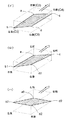
上記終端到達作動について、具体的に説明すると、例えば、図9(イ)に示すように、走行機体Vが左傾斜状態であるときに後上げスイッチ40bにて後上げ指令を指令して、機体姿勢を後上げ状態に変更させる手動ピッチング作動を実行する場合には、図9(ロ)に示すように、機体後部の上昇に伴って、駆動操作される左後シリンダC3と右後シリンダC5のうち、右後シリンダC5の方が先に上限位置に到達してピッチング作動が停止する。そこで、後上げスイッチ40bにて前記設定時間(例えば1.5秒)以上継続して後上げ指令を指令すると、上記手動ピッチング作動が再開されて、図9(ハ)に示すように、左後シリンダC3と右後シリンダC5が共に上限位置に到達するように作動され、機体姿勢を後上げ方向のエンド位置まで変更することができる。
尚、図中a、a0は、機体本体Vの左前端部での高さを示す。b、b1、b2は、機体本体Vの左後端部での高さを示す。c、c0は、機体本体Vの右前端部での高さを示す。d、d2は、機体本体Vの右後端部での高さを示す。
【0057】
前記姿勢制御手段200は、自動姿勢制御としてのローリング制御やピッチング制御を実行する自動制御モードにおいて、姿勢変更指令手段300の指令情報に基づいて手動姿勢制御を実行するときは、4個の油圧シリンダC2〜C5のうち機体本体における傾斜角変更方向の一端部に作用する一対の油圧シリンダの駆動操作を停止させた状態で、機体本体における傾斜角変更方向の他端部に作用する一対の油圧シリンダを姿勢変更指令手段300による傾斜変更指令の方向に駆動操作し、傾斜角変更方向の他端部に作用する一対の油圧シリンダが駆動操作可能範囲の終端位置に達したことを判別すると、引き続いて、その他端部に作用する一対の油圧シリンダを終端位置にて停止させた状態で、機体本体における傾斜角変更方向の一端部に作用する一対の油圧シリンダを姿勢変更指令手段による傾斜変更指令の方向に駆動操作するよう構成されている。
【0058】
又、前記姿勢制御手段200は、自動姿勢制御を実行しない自動停止モードにおいて、姿勢変更指令手段300の指令情報に基づいて手動姿勢制御を実行するときは、4個の油圧シリンダC2〜C5のうち機体本体における傾斜角変更方向の一端部に作用する一対の油圧シリンダの駆動操作を停止させた状態で、機体本体における傾斜角変更方向の他端部に作用する油圧シリンダを姿勢変更指令手段300による傾斜変更指令の方向に駆動操作する姿勢変更作動を実行し、且つ、傾斜角変更方向の他端部に作用する一対の油圧シリンダが駆動操作可能範囲の終端位置に達したことを判別すると、傾斜角変更方向の他端部に作用する一対の油圧シリンダの駆動操作を停止させ、その操作停止状態において、その駆動操作停止前の傾斜変更指令と同じ傾斜変更指令が姿勢変更指令手段300にて再度指令されると、傾斜角変更方向の他端部に作用する一対の油圧シリンダを駆動操作可能範囲の終端位置に保持させた状態で、傾斜角変更方向の一端部に作用する一対の油圧シリンダを姿勢変更指令手段300による傾斜変更指令の方向に駆動操作するように構成されている。
【0059】
説明を加えると、ローリング制御やピッチング制御を実行する自動制御モードになっている場合に、手動姿勢制御が優先的に実行されると、前記各ストロークセンサ18〜21の検出情報に基づいて、駆動操作している2個の油圧シリンダC2〜C5のいずれか一方がその駆動操作可能範囲の終端位置に到達したことが検出されると、そのとき、電子ブザーBZを作動させる報知作動を実行すると共に、それに引き続いて、他の2個の油圧シリンダを姿勢変更指令手段300による傾斜変更指令の方向に駆動操作させるのである。
そして、ローリング制御やピッチング制御を実行しない自動停止モードになっているとき、手動姿勢制御を実行するときには、前記各ストロークセンサ18〜21の検出情報に基づいて、駆動操作している2個の油圧シリンダC2〜C5のいずれか一方がその駆動操作可能範囲の終端位置に到達したことが検出されると、そのとき、電子ブザーBZを作動させる報知作動を実行すると共に、前記一方の2個の油圧シリンダの作動を停止させ、その後、駆動操作停止前の傾斜変更指令と同じ傾斜変更指令が姿勢変更指令手段300にて再度指令されると、傾斜角変更方向の他の一方の2個の油圧シリンダを駆動操作可能範囲の終端位置に保持させた状態で、他の2個の油圧シリンダを姿勢変更指令手段300による傾斜変更指令の方向に駆動操作するのである。
【0060】
次に、制御装置22による姿勢制御動作及び報知動作について、図10〜図15のフローチャートに基づいて説明する。
図10に示すように、先ず、手動操作指令(左右傾斜、前後傾斜、上下昇降)がされた否かを判断し、手動操作指令がされた場合には、手動姿勢制御を実行する。
上記手動操作指令がされていない場合は、水平自動スイッチ26と前後自動スイッチ27の状態を調べて、水平自動スイッチ26だけがオンしているときは自動ローリング作動だけを実行し、両方がオンしているときは、自動ローリング作動を優先して先に実行し、その後、自動ピッチング作動を実行する。
【0061】
図11に示すように、手動姿勢制御では、左右傾斜指令として、左上げスイッチ37bにて左上げが指令されていれば、右傾斜処理を実行し、右上げスイッチ37aにて右上げが指令されていれば、左傾斜処理を実行する。
前後傾斜指令として、後上げスイッチ40bにて後上げが指令されていれば、前傾斜処理を実行し、前上げスイッチ40aにて前上げが指令されていれば、後傾斜処理を実行する。
上下昇降指令として、機体上げスイッチ38aにて機体上げが指令されていれば、機体上昇処理を実行し、機体下げスイッチ38bにて機体下げが指令されていれば、機体下降処理を実行する。
【0062】
図12に示すように、右傾斜処理では、水平自動スイッチ26がオンして自動制御モードになっていれば、機体右側の前後のストロークセンサ20,21の検出情報に基づいて、右前シリンダC4と右後シリンダC5のいずれか一方が下限位置に操作されているか否かを判断し、両シリンダC4,C5がいずれも下限位置に操作されていなければ、右前シリンダC4を伸長作動させるとともに右後シリンダC5を短縮作動させる。各ストロークセンサ20,21の検出情報に基づいて右前シリンダC4と右後シリンダC5のいずれか一方が下限位置に操作されたことを判別すると、右前シリンダC4及び右後シリンダC5の駆動操作を停止させるとともに、終端位置に到達したことを報知する前記電子ブザーBZを作動させる。そして、それに引き続いて、機体左側の前後のストロークセンサ18,19の検出情報に基づいて、左前シリンダC2と左後シリンダC3のいずれか一方が上限位置に操作されているか否かを判断し、両シリンダC2,C3がいずれも上限位置に操作されていなければ、左前シリンダC2と左後シリンダC3のいずれか一方が上限位置に達するまで、左前シリンダC2を短縮作動させるとともに左後シリンダC3を伸長作動させ、いずれかが上限位置に達すると、左前シリンダC2と左後シリンダC3の駆動操作を停止する。そして、各シリンダC2〜C5が駆動停止しているときに、左上げ指令が設定時間(1.5秒)以上継続して指令されると、上述したような終端到達作動を実行する。
【0063】
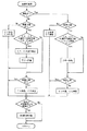
このような右傾斜処理を実行する結果、図16(イ)の(1)に示すように水平姿勢に維持されている状態から、右前シリンダC4と右後シリンダC5のいずれか一方が下限位置になるまで右傾斜し(図16(イ)の(2)参照)、更に、左前シリンダC2と左後シリンダC3のいずれか一方が上限位置に達するまで右傾斜が行われることになる(図16(イ)の(3)参照)。
このような処理は右傾斜以外の他の処理でも同様である。
【0064】
一方、水平自動スイッチ26がオフして自動停止モードになっていれば、次のように処理を実行する。つまり、機体右側の前後のストロークセンサ20,21の検出情報に基づいて、右前シリンダC4と右後シリンダC5のいずれか一方が下限位置に操作されているか否かを判断し、両シリンダC4,C5がいずれも下限位置に操作されていなければ、右前シリンダC4を伸長作動させるとともに右後シリンダC5を短縮作動させる。各ストロークセンサ20,21の検出情報に基づいて右前シリンダC4と右後シリンダC5のいずれか一方が下限位置に操作されたことを判別すると、右前シリンダC4及び右後シリンダC5の駆動操作を停止させるとともに、シリンダC4,C5が終端位置に到達したことを報知する前記電子ブザーBZを作動させる。そのとき左上げの指令が連続して与えられていれば操作停止状態を維持する(図16の(ロ)参照)。
そして、左上げスイッチ37bによる左上げの指令が一旦解除されて、その後、再度、左上げスイッチ37bによる左上げの指令があれば、機体左側の前後のストロークセンサ18,19の検出情報に基づいて、左前シリンダC2と左後シリンダC3のいずれか一方が上限位置に操作されているか否かを判断し、両シリンダC2,C3がいずれも上限位置に操作されていなければ、左前シリンダC2と左後シリンダC3のいずれか一方が上限位置に達するまで、左前シリンダC2を短縮作動させるとともに左後シリンダC3を伸長作動させ、いずれかが上限位置に達すると、左前シリンダC2と左後シリンダC3の駆動操作を停止する。そして、各シリンダC2〜C5が駆動停止しているときに、左上げ指令が設定時間(1.5秒)以上継続して指令されると、上記したような終端到達作動を実行する。
【0065】
図13に示すように、左傾斜処理では、水平自動スイッチ26がオンして自動制御モードになっていれば、機体左側の前後のストロークセンサ18,19の検出情報に基づいて、左前シリンダC2と左後シリンダC3のいずれか一方が下限位置に操作されているか否かを判断し、両シリンダC2,C3がいずれも下限位置に操作されていなければ、左前シリンダC2を伸長作動させるとともに左後シリンダC3を短縮作動させる。各ストロークセンサ18,19の検出情報に基づいていずれか一方が下限位置に操作されたことを判別すると、それら左前シリンダC2と左後シリンダC3の駆動操作を停止させるとともに、終端位置に到達したことを報知する前記電子ブザーBZを作動させる。そして、それに引き続いて、機体右側の前後のストロークセンサ20,21の検出情報に基づいて、右前シリンダC4と右後シリンダC5のいずれか一方が上限位置に操作されているか否かを判断し、両シリンダC4,C5がいずれも上限位置に操作されていなければ、いずれか一方が上限位置に達するまで、右前シリンダC4を短縮作動させるとともに右後シリンダC5を伸長作動させ、いずれかが上限位置に達するとそれらの駆動操作を停止する。そして、各シリンダC2〜C5が駆動停止しているときに、左上げ指令が設定時間(1.5秒)以上継続して指令されると、上記したような終端到達作動を実行する。
【0066】
一方、水平自動スイッチ26がオフして自動停止モードになっていれば、次のように処理を実行する。つまり、機体左側の前後のストロークセンサ18,19の検出情報に基づいて、左前シリンダC2と左後シリンダC3のいずれか一方が下限位置に操作されているか否かを判断し、両シリンダC2,C3がいずれも下限位置に操作されていなければ、左前シリンダC2を伸長作動させるとともに左後シリンダC3を短縮作動させる。各ストロークセンサ18,19の検出情報に基づいていずれか一方が下限位置に操作されたことを判別すると、左前シリンダC2と左後シリンダC3の駆動操作を停止させるとともに、シリンダC2,C3が終端位置に到達したことを報知する前記電子ブザーBZを作動させる。そのとき左上げの指令が連続して与えられていれば操作停止状態を維持する。
そして、右上げスイッチ37aによる右上げの指令が一旦解除されて、その後、再度、右上げスイッチ37aによる右上げの指令があれば、機体右側の前後のストロークセンサ20,21の検出情報に基づいて、右前シリンダC4と右後シリンダC5のいずれか一方が上限位置に操作されているか否かを判断し、両シリンダC4,C5がいずれも上限位置に操作されていなければ、それらのいずれか一方が上限位置に達するまで、右前シリンダC4を短縮作動させるとともに右後シリンダC5を伸長作動させ、いずれかが上限位置に達すると、右前シリンダC4と右後シリンダC5の駆動操作を停止する。そして、各シリンダC2〜C5が駆動停止しているときに、左上げ指令が設定時間(1.5秒)以上継続して指令されると、上記したような終端到達作動を実行する。
【0067】
図14に示すように、前傾斜処理では、水平自動スイッチ26がオンして自動制御モードになっていれば、機体前側の左右のストロークセンサ18,20の検出情報に基づいて、左前シリンダC2と右前シリンダC4のいずれか一方が下限位置に操作されているか否かを判断し、両シリンダC2,C4がいずれも下限位置に操作されていなければ、左前シリンダC2を伸長作動させるとともに右前シリンダC4を伸長作動させる。各ストロークセンサ18,20の検出情報に基づいて左前シリンダC2と右前シリンダC4のいずれか一方が下限位置に操作されたことを判別すると、それらの駆動操作を停止させるとともに、終端位置に到達したことを報知する前記電子ブザーBZを作動させる。そして、それに引き続いて、機体後側の左右のストロークセンサ19,21の検出情報に基づいて、左後シリンダC3と右後シリンダC5のいずれか一方が上限位置に操作されているか否かを判断し、両シリンダC3,C5がいずれも上限位置に操作されていなければ、左後シリンダC3と右後シリンダC5のいずれか一方が上限位置に達するまで、左後シリンダC3を伸長作動させるとともに右後シリンダC5を伸長作動させ、いずれかが上限位置に達するとそれらの駆動操作を停止する。そして、各シリンダC2〜C5が駆動停止しているときに、左上げ指令が設定時間(1.5秒)以上継続して指令されると、上記したような終端到達作動を実行する。
【0068】
一方、水平自動スイッチ26がオフして自動停止モードになっていれば、次のように処理を実行する。つまり、機体前側の左右のストロークセンサ18,20の検出情報に基づいて、左前シリンダC2と右前シリンダC4のいずれか一方が下限位置に操作されているか否かを判断し、両シリンダC2,C4がいずれも下限位置に操作されていなければ、左前シリンダC2を伸長作動させるとともに右前シリンダC4を伸長作動させる。各ストロークセンサ18,20の検出情報に基づいて左前シリンダC2と右前シリンダC4のいずれか一方が下限位置に操作されたことを判別すると、それらの駆動操作を停止させるとともに、終端位置に到達したことを報知する前記電子ブザーBZを作動させる。そのとき左上げの指令が連続して与えられていれば操作停止状態を維持する。
そして、後上げスイッチ40bによる後上げの指令が一旦解除されて、その後、再度、後上げスイッチ40bによる後上げの指令があれば、機体後側の左右のストロークセンサ19,21の検出情報に基づいて、左後シリンダC3と右後シリンダC5のいずれか一方が上限位置に操作されているか否かを判断し、両シリンダC3,C5がいずれも上限位置に操作されていなければ、左後シリンダC3と右後シリンダC5のいずれか一方が上限位置に達するまで、左後シリンダC3を伸長作動させるとともに右後シリンダC5を伸長作動させ、いずれかが上限位置に達するとそれらの駆動操作を停止する。そして、各シリンダC2〜C5が駆動停止しているときに、左上げ指令が設定時間(1.5秒)以上継続して指令されると、上記したような終端到達作動を実行する。
【0069】
図15に示すように、後傾斜処理では、水平自動スイッチ26がオンして自動制御モードになっていれば、機体後側の左右のストロークセンサ19,21の検出情報に基づいて、左後シリンダC3と右後シリンダC5のいずれか一方が下限位置に操作されているか否かを判断し、両シリンダC3,C5がいずれも下限位置に操作されていなければ、左後シリンダC3を短縮作動させるとともに右後シリンダC5を短縮作動させる。各ストロークセンサ19,21の検出情報に基づいて左後シリンダC3と右後シリンダC5のいずれか一方が下限位置に操作されたことを判別すると、それらの駆動操作を停止させるとともに、終端位置に到達したことを報知する前記電子ブザーBZを作動させる。そして、それに引き続いて、機体前側の左右のストロークセンサ18,20の検出情報に基づいて、左前シリンダC2と右前シリンダC4のいずれか一方が上限位置に操作されているか否かを判断し、両シリンダC2,C4がいずれも上限位置に操作されていなければ、いずれか一方が上限位置に達するまで、左前シリンダC2を短縮作動させるとともに右前シリンダC4を短縮作動させ、いずれかが上限位置に達すると、それらの駆動操作を停止する。そして、各シリンダC2〜C5が駆動停止しているときに、左上げ指令が設定時間(1.5秒)以上継続して指令されると、上記したような終端到達作動を実行する。
【0070】
一方、水平自動スイッチ26がオフして自動停止モードになっていれば、次のように処理を実行する。つまり、機体後側の左右のストロークセンサ19,21の検出情報に基づいて、左後シリンダC3と右後シリンダC5のいずれか一方が下限位置に操作されているか否かを判断し、両シリンダC3,C5がいずれも下限位置に操作されていなければ、左後シリンダC3を短縮作動させるとともに右後シリンダC5を短縮作動させる。各ストロークセンサ19,21の検出情報に基づいて左後シリンダC3と右後シリンダC5のいずれか一方が下限位置に操作されたことを判別すると、それらの駆動操作を停止させるとともに、終端位置に到達したことを報知する前記電子ブザーBZを作動させる。そのとき左上げの指令が連続して与えられていれば操作停止状態を維持する。
そして、前上げスイッチ40aによる前上げの指令が一旦解除されて、その後、再度、前上げスイッチ40aによる前上げの指令があれば、機体前側の前後のストロークセンサ18,20の検出情報に基づいて、左前シリンダC2と右前シリンダC4のいずれか一方が上限位置に操作されているか否かを判断し、両シリンダC2,C4がいずれも上限位置に操作されていなければ、左前シリンダC2と右前シリンダC4のいずれか一方が上限位置に達するまで、左前シリンダC2を短縮作動させるとともに右前シリンダC4を短縮作動させ、いずれかが上限位置に達するとそれらの駆動操作を停止する。そして、各シリンダC2〜C5が駆動停止しているときに、左上げ指令が設定時間(1.5秒)以上継続して指令されると、上記したような終端到達作動を実行する。
【0071】
〔別実施形態〕
次に別実施形態を列記する。
【0072】
(1)上記実施形態では、前記自動制御モード及び前記自動停止モードの夫々において、姿勢変更指令手段の指令情報に基づいて前記手動姿勢制御を実行するときに、傾斜角変更方向の他端部に作用する駆動手段(油圧シリンダ)が駆動操作可能範囲の終端位置に達したことを判別すると報知作動を実行する構成としたが、このような構成に限らず、前記自動制御モード及び前記自動停止モードのいずれか一方において、前記報知作動を実行するようにしてもよく、又、このような報知作動を実行しない構成としてもよい。
【0073】
(2)上記実施形態では、前記ローリング作動及び前記ピッチング作動の夫々を実行する構成としたが、このような構成に限らず、前記ローリング作動及び前記ピッチング作動のうちのいずれか一方を実行するような構成としてもよく、又、前記ローリング作動と前記ピッチング作動とを夫々各別に実行するのではなく、例えば、4個の駆動手段のうちの1つを作動停止した状態で、他の3つの駆動手段を操作しながら、斜め方向に姿勢を変更させるような姿勢変更操作を行う構成としてもよい。
【0074】
(3)上記実施形態では、走行装置を、左右一対のクローラ走行装置1R,1Lで構成したが、これに限るものではなく、例えば、単一の走行装置でもよく、又、クローラ式ではなく車輪式の走行装置でもよい。
【0075】
(4)上記実施形態では、姿勢変更操作手段100を構成する4個の駆動手段C2〜C5を油圧シリンダにて構成したが、これに限るものではなく、電動モータとネジ送り機構等からなる他の駆動手段にて構成してもよい。
【0076】
(5)上記実施形態では、作業車としてコンバインを例示したが、コンバインに限らず、苗移植機やトラクター等の他の農作業車でもよく、農作業車に限らず、建設用の作業車や土木用の作業車であってもよい。
【図面の簡単な説明】
【図1】コンバインの前部を示す側面図
【図2】走行装置の昇降操作構成を示す側面図
【図3】走行装置の昇降操作構成を示す側面図
【図4】走行装置の昇降操作構成を示す側面図
【図5】走行装置の昇降操作構成を示す側面図
【図6】制御構成を示すブロック図
【図7】姿勢変更操作用のスイッチユニットの正面図
【図8】ローリング作動状態を示す正面図
【図9】終端到達作動を説明する斜視図
【図10】制御作動を示すフローチャート
【図11】制御作動を示すフローチャート
【図12】制御作動を示すフローチャート
【図13】制御作動を示すフローチャート
【図14】制御作動を示すフローチャート
【図15】制御作動を示すフローチャート
【図16】車体の姿勢変化を示す動作説明図
【符号の説明】
1R,1L 走行装置
18〜21 操作量検出手段
23 左右傾斜角検出手段
24 前後傾斜角検出手段
100 姿勢変更操作手段
200 制御手段
300 姿勢変更指令手段
C2〜C5 駆動手段
V 機体本体[0001]
BACKGROUND OF THE INVENTION
The present invention provides a posture change operation means that can freely change the inclination angle of the airframe body with respect to the grounding portion of the traveling device, an inclination angle detection means that detects an inclination angle with respect to a horizontal reference plane of the airframe body, and an inclination of the airframe body Based on the detection information of the manual attitude change command means for instructing a change instruction and the inclination angle detection means, the attitude change is performed so that the inclination angle with respect to the horizontal reference plane of the airframe body is maintained at the set inclination angle. An automatic attitude control that controls the operation of the operation means and a manual attitude control that controls the operation of the attitude change operation means based on the command information of the attitude change command means are changed from the automatic attitude control to the manual attitude. Control means for executing control in a state in which control is prioritized, and the control means controls the automatic attitude control based on command information of a control state switching means for commanding on / off of the automatic attitude control. An automatic control mode to be executed, about the posture control apparatus for working vehicle that is configured to be freely switched between the automatic stop mode without executing the automatic attitude control.
[0002]
[Prior art]
The posture control device for a work vehicle having the above configuration is applied to a work vehicle such as a combine harvester that harvests planted stems in a field. For example, when working in a wet field in a combine, As the vehicle runs, it becomes a state of rear inclination, and the height of cutting by the reaping part may not be at an appropriate position, or the threshing device may be inclined and threshing and poor sorting may easily occur. In this case, if the posture of the machine body is changed to a state in which the machine body is inclined forward with respect to the grounding portion of the traveling device, the cutting height position may be appropriately adjusted, or threshing and sorting may be appropriately performed. Moreover, in the field, there are irregularities on the running surface, and due to the irregularities, the aircraft body may tilt in the left-right direction, but even in such a left-right tilted state, the threshing device is tilted This often leads to threshing and poor sorting. In this case, if the posture of the machine body is changed to a state in which it is inclined to the left or to the right with respect to the grounding portion of the traveling device, threshing and sorting processing may be appropriately performed. Therefore, in normal mowing work in the field, by executing the automatic attitude control based on the detection information of the inclination angle detection means, the inclination angle with respect to the horizontal reference plane of the machine body is corrected and appropriate work is performed. It can be done.
[0003]
Also, when performing cutting work in the field as described above, when performing work near the shore where the ground is often rough, or to go over the fence to enter and exit the field When the automatic posture control as described above is executed, the posture changing operation different from the direction intended by the operator may be performed, or the posture changing operation may not be in time for the posture change of the aircraft body. is there. Therefore, in such a case, by switching to the automatic stop mode and operating the attitude change command means, the control means controls the operation of the attitude change operation means based on the command from the attitude change command means, and the body body The inclination angle of the traveling device with respect to the grounding portion can be adjusted.
[0004]
In this type of work vehicle, conventionally, the tilt angle of the machine body with respect to the traveling device is adjusted by swinging the body frame of the machine body with respect to the traveling device around one horizontal axis. It was.
[0005]
[Problems to be solved by the invention]
However, in the above conventional configuration, the maximum change amount of the tilt angle that can be operated when changing the attitude of the airframe main body cannot be increased, or the driving means for moving and adjusting the airframe main body with respect to the traveling device is enlarged. There were disadvantages, and the stability of the aircraft was likely to decrease.
That is, conventionally, the inclination angle of the aircraft body with respect to the grounding portion of the traveling device is adjusted by swinging the aircraft frame of the aircraft body around the horizontal axis with respect to the traveling device. From the above, if it is attempted to increase the amount of change in the inclination angle of the aircraft body with respect to the grounding part of the traveling device, it is necessary to increase the vertical movement amount of the aircraft frame, and there is a large stroke as a driving means for performing the moving operation. It was necessary to adopt. Further, in order to increase the tilt angle, it is necessary to increase the vertical distance between the aircraft frame and the traveling device, and the center of gravity of the aircraft body is high when the aircraft body is in a horizontal posture.
[0006]
As what can adjust inclination while improving this point, for example, as shown in JP-A-2001-260959, as the posture change operation means, the travel at both end portions in the inclination angle change direction of the body body A structure for performing the automatic attitude control by providing a plurality of drive means capable of changing and adjusting the height of the apparatus with respect to the grounding part so that the attitude of the main body can be greatly changed. Was considered.
According to this configuration, when the inclination adjustment to the grounding portion of the traveling device of the aircraft body is performed by operating a plurality of driving means, the size of the driving means, the range in which the inclination adjustment is possible, the stability of the aircraft, etc. It is possible to adjust the inclination while improving the surface.
That is, one end side maximum inclination state in which one end portion of the machine body is moved to the lowering limit with respect to the grounding portion of the traveling device, and the other end portion is moved to the rising limit with respect to the grounding portion of the traveling device; The machine body between one end of the main body is moved to the rising limit with respect to the grounding part of the traveling device and the other end is moved to the lowering limit with respect to the grounding part of the traveling device. The tilt can be adjusted so that the tilt angle of the main body changes. This makes it possible to increase the amount of change in the tilt angle while reducing the maximum stroke in which the machine body moves relative to the grounding portion of the traveling device and lowering the center of gravity of the machine when the machine body is in a horizontal posture.
[0007]
Therefore, in adopting a configuration in which the height adjustment with respect to the grounding portion of the traveling device at each of both end portions in the inclination angle changing direction in the airframe body is adjusted by a plurality of driving means that can be changed and adjusted individually. The control means for operating the plurality of drive means based on the command from the attitude change command means simultaneously drives and operates the drive means acting on one end portion of the machine body and the drive means acting on the other end portion. When the posture changing operation is executed, a large amount of power is required so that all the driving means can be driven at once. In addition, it is necessary to set control target positions for all the driving means and control to the control target positions, and it is necessary to perform complicated signal processing.
[0008]
Further, when the configuration for performing the tilt adjustment by a plurality of driving means as the posture changing operation means and performing the manual posture control in preference to the automatic posture control is described above. If the posture can be changed greatly between the one-end-side maximum inclination state and the other-end-side maximum inclination state, the posture change amount becomes too large, and it may be difficult to perform the vehicle operation.
In other words, with the above configuration, it may be difficult for the operator to determine the relative posture of the aircraft body with respect to the grounding surface of the traveling device, for example, near the shore where the ground is often rough. When the posture is changed by manual operation, such as when performing the above-mentioned work traveling or when going over the ridge to enter or exit the field, the relative posture of the aircraft body with respect to the grounding surface of the traveling device is Since it is difficult to determine how it is, for example, if there is an operation error, there is a risk that the aircraft body will be excessively inclined with respect to the ground contact surface of the traveling device, causing the aircraft posture to become unstable.
[0009]
Therefore, in order to eliminate such disadvantages, when performing manual attitude control, based on the command information of the attitude change command means, only the driving means at one end of the body body is connected to the grounding part of the traveling device. When the operation limit is reached and the operation limit is reached, an improved configuration is considered in which the operation is stopped. However, in such a configuration, the posture is largely changed based on the manual posture control. If necessary, such an operation cannot be performed properly.
In addition, when manual posture control is executed by the command of the posture change command means, only the driving means at one end of the machine body is operated, and when it reaches the operation limit, the operation is stopped there, for example, There is a case where there is a puddle with a high pile of swarf etc. in the middle of working on the field, or there is a plow with a large projecting ground on the front of the machine body in the upright work etc. In order to avoid such trap accumulation, protruding wrinkles, and the like, there is a case where the attitude of the airframe body is greatly inclined, but the above-described improved configuration cannot perform such attitude correction.
[0010]
In addition, when the automatic attitude control is executed, when the attitude is changed by executing the manual attitude control with priority over the automatic attitude control, the driving means at the one end of the machine body as described above is operated. When the limit is reached, the operation is stopped there, so if the command of the attitude change command means is canceled at that time, it returns to automatic attitude control, and the tilt angle of the aircraft body is adjusted to the set tilt angle, again, Even if the posture change command means is commanded, there is an inconvenience that a desired tilt state cannot be obtained only by repeatedly performing the same operation.
[0011]
The present invention has been made paying attention to such points, and its purpose is to provide advantages in terms of the size of the driving means and the stability of the airframe when enabling the attitude change operation of the airframe body. An attitude control device for a work vehicle that can perform adjustment operation by manual attitude control in an appropriate state according to the situation while increasing the adjustment range to be advantageous from the viewpoint of driving force and control. The point is to provide.
[0012]
[Means for Solving the Problems]
The posture control device for a work vehicle according to
An inclination angle detecting means for detecting an inclination angle with respect to a horizontal reference plane of the airframe body;
Manual attitude change command means for instructing an inclination change command of the body, and
Automatic attitude control for controlling the operation of the attitude changing operation means so that an inclination angle with respect to a horizontal reference plane of the airframe body is maintained at a set inclination angle based on detection information of the inclination angle detection means; and Control means for executing each of the manual attitude control for controlling the operation of the attitude change operation means in a state in which the manual attitude control is prioritized over the automatic attitude control based on the command information of the attitude change command means. ,
Based on the command information of the control state switching means for commanding on / off of the automatic attitude control, the control means is in an automatic control mode in which the automatic attitude control is executed and an automatic stop mode in which the automatic attitude control is not executed. It is configured to be switchable,
The posture change operation means includes a plurality of drive means that can change and adjust the height with respect to the grounding portion of the traveling device at each of both ends in the inclination angle change direction in the airframe body, An operation amount detection means for detecting the drive operation amount of each drive means is provided,
The control means is
In the automatic control mode, when the manual posture control is executed based on the command information of the posture change command means, the drive acting on one end portion in the tilt angle change direction in the body main body among the plurality of drive means. In a state where the driving operation of the means is stopped, the driving means acting on the other end portion in the inclination angle changing direction in the main body is driven in the direction of the inclination changing command by the attitude changing command means, and the operation amount detecting means When it is determined that the driving means acting on the other end in the inclination angle changing direction has reached the end position of the drive operable range based on the detected information, the driving means is subsequently stopped at the end position. In such a state, the driving means acting on one end portion in the inclination angle changing direction of the airframe body is driven to operate in the direction of the inclination changing command by the attitude changing command means. , And,
In the automatic stop mode, when the manual posture control is executed based on the command information of the posture change command means, the drive acting on one end portion of the body main body in the inclination angle change direction among the plurality of drive means In a state where the driving operation of the means is stopped, a posture changing operation is performed in which the driving means acting on the other end portion in the inclination angle changing direction in the airframe body is driven in the direction of the inclination changing command by the posture changing command means. And when it is determined that the driving means acting on the other end in the inclination angle changing direction has reached the end position of the drive operable range based on the detection information of the operation amount detection means, The driving operation of the driving means acting on the other end portion in the angle changing direction is stopped, and in the operation stopped state, the same inclination changing command as the inclination changing command before stopping the driving operation is changed to the posture changing When commanded again by the commanding means, the driving means acting on the other end portion in the tilt angle changing direction acts on one end portion in the tilt angle changing direction with the driving means being held at the end position of the drive operable range. The driving means is configured to be driven in the direction of the inclination change command by the posture change command means.
[0013]
According to the above configuration, the posture changing operation means includes a plurality of driving means that can individually change and adjust the height of the traveling device with respect to the grounding portion at both ends in the inclination angle changing direction of the main body. Therefore, one end of the machine body is lowered with respect to the grounding portion of the traveling device by appropriately operating the plurality of drive means by the control means that operates based on the command from the attitude change command means. One end side maximum tilt state where the other end is at the upper limit with respect to the grounding part of the traveling device and the other end is at the upper limit with respect to the grounding part of the traveling device. Inclination can be adjusted such that the inclination angle of the airframe body changes between the maximum inclination state on the other end side which is at the lower limit with respect to the ground contact portion. This makes it possible to increase the amount of change in the tilt angle while reducing the maximum stroke in which the machine body moves relative to the grounding portion of the traveling device and lowering the center of gravity of the machine when the machine body is in a horizontal posture.
[0014]
Further, the control means operates the driving means acting on the other end portion in a state where the driving means acting on the one end portion in the direction of changing the tilt angle of the machine body is stopped when performing the manual attitude control. Therefore, when driving the drive means so as to change the tilt angle, it is possible to use a small driving force as a whole for the number and size of the drive means provided compared to the case where all the drive means are controlled simultaneously. In addition, it is possible to cope with signal processing that is relatively simple.
[0015]
Then, when executing the manual attitude control in the automatic stop mode, the control means acts on the other end in a state where the drive operation of the drive means acting on the one end in the inclination angle changing direction in the main body is stopped. Driving the driving means in the direction of the inclination change command, and when it is determined that the driving means acting on the other end has reached the end position of the drive operable range, the driving operation of the driving means acting on the other end is performed. It is made to stop (for example, refer to (B) in FIG. 16). In this way, when automatic posture control is not performed, such as when overrunning the heel or when running on the shore, the driving means acting on the other end has reached the end position of the drive operable range. Since the operation is stopped in a state, even if there is an operation error or the like, the airframe body does not greatly tilt with respect to the grounding portion of the traveling device, and the posture of the airframe can be easily stabilized.
[0016]
In such an operation stop state, when the same tilt change command as the tilt change command before stopping the drive operation is commanded again by the posture change command means, the drive means acting on the other end portion in the tilt angle change direction Is held at the end position of the drive operation possible range, and the drive means acting on one end portion in the inclination angle change direction is driven and operated in the direction of the inclination change command by the attitude change command means. As described above, it is possible to further change the attitude of the fuselage with the operator recognizing that the driving means acting on the other end has reached the end position of the drive operable range. Can be greatly inclined in a desired direction.
In the operation stop state as described above, even if the command by the posture change command means is once released, the automatic posture control is not performed at that time, so the posture is not changed, The posture can be changed.
[0017]
By the way, when in the automatic control mode, as in the case of the automatic stop mode as described above, when it is determined that the driving means acting on the other end has reached the end position of the drive operation possible range, If the driving operation of the acting driving means is stopped, when the command of the attitude change command means is canceled in the stopped state, the state returns to the state in which the automatic attitude control is executed, and the inclination angle of the main body is changed. It will be automatically adjusted to the set inclination angle. Therefore, even if the attitude change command means is commanded again in order to largely tilt the attitude of the aircraft in a desired direction, the same tilting operation is repeatedly performed and the desired tilt state cannot be obtained. Become.
[0018]
Therefore, when executing the manual attitude control in the automatic control mode, the control means acts on the other end portion in a state in which the driving operation of the drive means acting on the one end portion in the inclination angle changing direction in the main body is stopped. When the drive means is driven in the direction of the inclination change command, and it is determined that the drive means acting on the other end portion has reached the end position of the drive operable range, the drive means is subsequently moved to the end position. In a stopped state, the driving means acting on the one end is driven in the direction of the inclination change command.
By configuring in this way, for example, as shown in FIG. 16A, the driving means acting on the other end portion continues without stopping in a state where the driving means has reached the end position of the drive operable range. The attitude of the fuselage main body can be largely changed until the maximum tilt state is reached in the direction of the tilt change command.
[0019]
Then, for example, automatic posture control is performed to properly perform work during work travel, but during such work travel, traps and large protrusions that exist in the middle of the travel route are removed. Even if you want to greatly tilt the attitude of the aircraft body to avoid it, it is possible to largely change the attitude and avoid it, so that the attitude of the aircraft can be greatly inclined in the desired direction. . During such work traveling, the traveling surface is relatively stable, and even if the aircraft is tilted greatly, there is little possibility that the aircraft will become unstable like when over the heel.
[0020]
Therefore, when enabling the attitude change operation of the fuselage main body, it is advantageous from the aspect of driving force and control by increasing the adjustment range while improving the advantages of the size of the driving means and the stability of the aircraft. Thus, it has become possible to provide an attitude control device for a work vehicle that can perform an adjustment operation by manual attitude control in an appropriate state according to the situation.
[0021]
According to a second aspect of the present invention, there is provided the work vehicle attitude control device according to the first aspect, wherein the control means executes the manual attitude control based on command information of the attitude change command means in the automatic control mode. When the driving means acting on the other end of the tilt angle changing direction determines that the end position of the drive operation possible range has been reached, a notification operation is executed, and in the automatic stop mode, the posture change command means When performing the manual attitude control based on the command information, a notification operation is performed when it is determined that the driving means acting on the other end portion in the inclination angle changing direction has reached the end position of the drive operable range. It is configured.
[0022]
That is, in both the automatic control mode and the automatic stop mode, the notification operation is executed when it is determined that the driving means acting on the other end has reached the end position of the drive operable range. The person can recognize that the driving means acting on the other end portion has reached the end position of the drive operation possible range by the notification operation, and the relative posture of the airframe body with respect to the ground contact surface of the traveling device at that time is determined. It can be judged whether it is.
[0023]
Therefore, it is possible to avoid the instability of the aircraft body due to the large inclination of the fuselage body with respect to the grounding part of the traveling device, and the subsequent operation can be performed appropriately, and the operation for changing the posture is performed. It becomes easy, and means suitable for carrying out
[0024]
The posture control apparatus for a work vehicle according to
The inclination angle detecting means is
A right / left inclination angle detecting means for detecting a left / right inclination angle with respect to a horizontal reference plane of the airframe body, and a front / rear inclination angle detecting means for detecting a front / rear inclination angle with respect to the horizontal reference surface of the airframe body,
The posture change command means is configured to command each of a left tilt command, a right tilt command, a front tilt command, and a rear tilt command of the body as the tilt change command,
The control means is
Of the four driving means, two of the two driving means located at the left front and left rear and the two driving means located at the right front and right rear A rolling operation for driving the other two driving means in a state where the driving of the means is stopped, and two driving means and a left side of the four driving means located at the left front part and the right front part. A pitching operation for driving the other two driving means is executed in a state where driving of any one of the two driving means located at the rear portion and the right rear portion is stopped. And configured as
As the automatic attitude control, based on the detection information of the left / right inclination angle detection means, rolling control for executing the rolling operation so that the left / right inclination angle with respect to the horizontal reference plane of the airframe body is maintained at the set left / right inclination angle; And, based on the detection information of the front / rear inclination angle detecting means, the pitching control is executed to execute the pitching operation so that the front / rear inclination angle with respect to the horizontal reference plane of the body is maintained at the set front / rear inclination angle. And
As the manual posture control, the rolling operation is executed when the left tilt command and the right tilt command are commanded, and the pitching operation is performed when the front tilt command and the rear tilt command are commanded. It is comprised so that may be performed.
[0025]
That is, the posture changing operation means includes two driving means located at the left front part and the left rear part among the four driving means, and two driving means located at the right front part and the right rear part. By executing a rolling operation that drives the other two drive means in a state where the drive of any one of the two drive means is stopped, the posture of the body can be changed in the front-rear direction, Of the four drive means, two of the two drive means located at the left front part and the right front part, and two of the two drive means located at the left rear part and the right rear part, By executing the pitching operation for driving the other two driving means in a state where the driving means is stopped, it is possible to change the posture of the body body from side to side.
[0026]
In the automatic control mode, the rolling control and the pitching control are executed as the automatic attitude control, respectively, so that the horizontal tilt angle with respect to the horizontal reference plane of the main body is maintained at the set horizontal tilt angle, and the recording body main body By automatically controlling so that the front / rear inclination angle with respect to the horizontal reference plane is maintained at the set front / rear inclination angle, the work can be performed while maintaining an appropriate posture in each of the left / right direction and the front / rear direction.
[0027]
Further, when the left tilt command and the right tilt command are commanded by the posture change command means, the rolling operation is executed in the commanded direction, so that the left front part and the left rear part in the body body From the rightmost inclined posture in which each of the right front part and the right rear part is lowered to the lowering limit with respect to the grounding part of the traveling device by raising each to the grounding part of the traveling device to the rising limit, Up to the leftmost inclined posture in which each of the front and right rear portions is raised to the ascent limit with respect to the grounding portion of the traveling device, and each of the left front portion and the left rear portion is lowered to the descending limit with respect to the grounding portion of the traveling device. The posture changing operation can be performed in a wide operation range in the left-right direction.
When the front inclination command and the rear inclination command are instructed by the attitude change command means, the pitching control is executed in the commanded direction, so that the left rear portion and the right rear portion of the main body are traveled. From the foremost inclined posture in which the left front part and the right front part are lowered to the lowering limit with respect to the grounding part of the traveling apparatus by raising the grounding part of the apparatus to the ascent limit, the left front part and the right side in the body body Wide in the front-rear direction to the last tilted posture in which each front part is raised to the rising limit with respect to the grounding part of the traveling device, and each of the left rear part and the right rear part is lowered to the lowering limit with respect to the grounding part of the traveling device. The posture changing operation can be performed in the operation range.
[0028]
Therefore, the center of gravity of the aircraft body when the aircraft body is in a horizontal position is reduced while minimizing the maximum stroke that the aircraft body moves with respect to the grounding portion of the traveling device with respect to the lateral direction and the longitudinal direction. The amount of change in the tilt angle can be increased while lowering, and automatic posture control and manual posture control can be performed stably in a wide operation range with respect to both the left and right directions and the front and rear directions. Alternatively, a suitable means for carrying out 2 is obtained.
[0029]
DETAILED DESCRIPTION OF THE INVENTION
DESCRIPTION OF EMBODIMENTS Hereinafter, an embodiment of an attitude control device for a work vehicle according to the present invention will be described with reference to the drawings.
[0030]
FIG. 1 shows a combine as an example of a work vehicle. The combine is configured to be supported by a pair of left and right
[0031]
That is, the cutting
[0032]
As shown in FIG. 2, the
[0033]
Of the front bell crank 17a, a swingable arm extending so as to be integrally rotatable from a rotation support shaft portion rotatably connected to the
That is, the front cylinder C2 rotates the front bell crank 17a around the axis P2 with respect to the
[0034]
The right
[0035]
Accordingly, as shown in FIG. 2, when the left and right front cylinders C2 and C4 are extended to the maximum and the left and right rear cylinders C3 and C5 are shortened to the shortest, the track frames 16 of the left and right traveling
[0036]
As shown in FIG. 3, when the left and right front cylinders C2 and C4 are shortened while maintaining the left and right rear cylinders C3 and C5 as they are in the lower limit reference posture, the left and right traveling
As shown in FIG. 4, when the left and right rear cylinders C3 and C5 are extended while maintaining the left and right front cylinders C2 and C4 from the lower limit reference posture, the left and right traveling
As shown in FIG. 5, when the left and right front cylinders C2 and C4 are shortened and the left and right rear cylinders C3 and C5 are extended and operated from the lower limit reference posture, the left and right traveling
[0037]
When the hydraulic cylinders C2 to C5 are operated on the side where the vertical distance between the
[0038]
When the hydraulic cylinders C2 to C5 are operated on the side where the vertical distance between the
[0039]
Accordingly, the left front cylinder C2 (hereinafter simply referred to as the left front cylinder C2), the left rear cylinder C3 (hereinafter simply referred to as the left rear cylinder C3), and the right front cylinder C4 (hereinafter simply referred to as the left front cylinder C3). The right front cylinder C4) and the right rear cylinder C5 (hereinafter simply referred to as the right rear cylinder C5) are the right and left inclination angles and the front and rear inclinations of the vehicle body V with respect to the ground contact portions of the traveling
[0040]
In the left and right
Also, the machine body V has a gravitational left / right
[0041]
As shown in FIG. 6, the detection information of each of the
[0042]
The posture change switch unit SU includes a left / right tilt
[0043]
When the
Also, when the operating
[0044]
The
[0045]
Therefore, if the right-
[0046]
The left / right tilt
[0047]
On the other hand, the
[0048]
A control means 200 for controlling the operation of the attitude changing operation means 100 is configured by using the
[0049]
The control means 200 performs a rolling operation and a pitching operation as a control form, which includes automatic control and manual control executed based on a manual operation command.
In the case of automatic control, the control means 200 sets the left / right inclination angle of the main body V by the left / right inclination
The execution of the rolling control is commanded when the horizontal
[0050]
In the case of manual control, when the control means 200 is instructed as a manual attitude control based on the command information of the attitude change command means 300, a left tilt command (right-up command) is issued. The left / right tilt angle is changed to the left tilt side, and when a right tilt command (left-up command) is commanded, a rolling operation is performed so as to change the left / right tilt angle of the machine body V to the right tilt side, Based on the command information of the attitude change command means 300, when a front tilt command (aircraft rear raising command) is commanded, the front / rear tilt angle of the airframe main body V is changed to the front tilt side, and a rear tilt command (aircraft front up) When the command is commanded, the pitching operation is executed so that the front / rear tilt angle of the body V is changed to the rear tilt side.
[0051]
When an ascending command is instructed by the
[0052]
Next, the rolling operation and the pitching operation in the lower limit reference mode will be described.
That is, in the case of the rolling operation, when the left front cylinder C2 is shortened and the left rear cylinder C3 is extended from the state in the lower limit reference posture (FIG. 2), as shown in FIG. Then, the fuselage main body V changes to a left-upward inclined posture (right inclined posture) with respect to the grounding portion. Further, when the right front cylinder C4 is shortened and the right rear cylinder C5 is extended from the lower limit reference posture, as shown in FIG. It will change to the upper right tilt posture (left tilt posture). In this way, it is possible to execute a rolling operation in which the main body V is tilted in the left-right direction with respect to the grounding portions of the traveling
[0053]
On the other hand, in the case of the pitching operation, the left front cylinder C2 and the right front cylinder C4 are simultaneously shortened while maintaining the left rear cylinder C3 and the right rear cylinder C5 as they are from the state of the lower limit reference posture (FIG. 2). If it does so, the front part side of the machine body main body V will raise with respect to each grounding part of the left and right
[0054]
Although description of the rolling operation and the pitching operation in the upper limit reference mode is omitted, the machine body V is in the most separated posture in the left and right
[0055]
In the manual posture control, the posture control means 200 performs two driving operations based on detection information of the
Specifically, the end position of the drive operable range of each hydraulic cylinder C2 to C5 corresponds to the upper limit position and the lower limit position of the full stroke of each hydraulic cylinder C2 to C5.
[0056]
More specifically, the end reaching operation will be described. For example, as shown in FIG. 9 (a), when the traveling machine body V is in the left-tilt state, a rear raising command is issued by the
In the figure, a and a0 indicate the height at the front left end of the main body V. “b”, “b1”, and “b2” indicate the height at the left rear end of the main body V. c and c0 indicate the height at the right front end of the main body V. d and d2 indicate the height at the right rear end of the main body V.
[0057]
When the posture control means 200 executes manual posture control based on the command information of the posture change command means 300 in the automatic control mode for executing rolling control or pitching control as automatic posture control, four hydraulic cylinders are used. A pair of hydraulic cylinders acting on the other end portion in the tilt angle changing direction in the fuselage body in a state where driving operation of the pair of hydraulic cylinders acting on one end portion in the tilt angle changing direction in the fuselage body is stopped among C2 to C5 Is driven in the direction of the tilt change command by the posture change command means 300, and it is determined that the pair of hydraulic cylinders acting on the other end in the tilt angle change direction has reached the end position of the drive operable range. In a state where the pair of hydraulic cylinders acting on the other end portions are stopped at the end positions, the one end portion in the tilt angle changing direction in the body body It is configured to drive the operation of the pair of hydraulic cylinders in the direction of the inclination change command according to the posture change instruction means for use.
[0058]
When the posture control means 200 executes the manual posture control based on the command information of the posture change command means 300 in the automatic stop mode in which the automatic posture control is not executed, the posture control means 200 includes the four hydraulic cylinders C2 to C5. With the posture change command means 300, the hydraulic cylinder acting on the other end portion in the tilt angle changing direction in the main body is stopped while the drive operation of the pair of hydraulic cylinders acting on one end portion in the tilt angle changing direction in the main body is stopped. When it is determined that the posture change operation for driving in the direction of the inclination change command is executed and the pair of hydraulic cylinders acting on the other end portion in the inclination angle change direction has reached the end position of the drive operable range, The drive operation of the pair of hydraulic cylinders acting on the other end in the angle change direction is stopped, and in the operation stop state, the inclination change command before the drive operation stop and When the same inclination change command is issued again by the attitude change command means 300, the inclination angle is changed with the pair of hydraulic cylinders acting on the other end in the inclination angle changing direction being held at the end position of the drive operable range. A pair of hydraulic cylinders acting on one end portion in the changing direction is configured to be driven in the direction of the inclination changing command by the attitude changing command means 300.
[0059]
In other words, when manual posture control is preferentially executed in the automatic control mode in which rolling control or pitching control is executed, driving is performed based on the detection information of the
And when it is in the automatic stop mode which does not perform rolling control or pitching control, when performing manual attitude control, it is based on the detection information of each said stroke sensors 18-21, and two hydraulic pressures which are drive-operated When it is detected that any one of the cylinders C2 to C5 has reached the end position of the drive operable range, at that time, a notification operation for operating the electronic buzzer BZ is executed, and the one of the two hydraulic pressures When the operation of the cylinder is stopped and then the same inclination change command as the inclination change command before the stop of the driving operation is again commanded by the attitude change command means 300, the other two hydraulic cylinders in the other direction of inclination angle change Is held at the end position of the drive operable range, and the other two hydraulic cylinders are driven in the direction of the inclination change command by the attitude change command means 300. Than it is.
[0060]
Next, the attitude control operation and the notification operation by the
As shown in FIG. 10, first, it is determined whether or not a manual operation command (right / left tilt, front / back tilt, up / down ascending / descending) is issued, and when a manual operation command is issued, manual attitude control is executed.
When the manual operation command is not issued, the state of the horizontal
[0061]
As shown in FIG. 11, in the manual attitude control, if left-up
As the front / rear tilt command, if the rear raising is commanded by the
As the up / down raising / lowering command, if the
[0062]
As shown in FIG. 12, in the right tilt process, if the horizontal
[0063]
As a result of executing such right inclination processing, one of the right front cylinder C4 and the right rear cylinder C5 is brought to the lower limit position from the state where it is maintained in the horizontal posture as shown in FIG. (See (2) of FIG. 16 (a)), and further, right inclination is performed until either one of the left front cylinder C2 or the left rear cylinder C3 reaches the upper limit position (FIG. 16 ( (See b) (3)).
Such a process is the same for other processes than the right inclination.
[0064]
On the other hand, if the horizontal
Then, if the left raising command by the
[0065]
As shown in FIG. 13, in the left tilt process, if the horizontal
[0066]
On the other hand, if the horizontal
Then, if the command for raising the right by the
[0067]
As shown in FIG. 14, in the forward tilt process, if the horizontal
[0068]
On the other hand, if the horizontal
Then, if the back-up command by the back-up
[0069]
As shown in FIG. 15, in the rear tilt process, if the horizontal
[0070]
On the other hand, if the horizontal
Then, if the front-up command by the front-up
[0071]
[Another embodiment]
Next, another embodiment will be listed.
[0072]
(1) In the above embodiment, when the manual posture control is executed based on the command information of the posture change command means in each of the automatic control mode and the automatic stop mode, the other end portion in the inclination angle change direction is When it is determined that the actuating drive means (hydraulic cylinder) has reached the end position of the drive operable range, the notification operation is executed. However, the present invention is not limited to this configuration, and the automatic control mode and the automatic stop mode are not limited thereto. In any one of the above, the notification operation may be executed, or such a notification operation may not be executed.
[0073]
(2) In the above-described embodiment, each of the rolling operation and the pitching operation is performed. However, the present invention is not limited to such a configuration, and any one of the rolling operation and the pitching operation is performed. Also, the rolling operation and the pitching operation are not performed separately, but the other three driving devices are operated with one of the four driving means stopped. It is good also as a structure which performs attitude | position change operation which changes an attitude | position to the diagonal direction, operating a means.
[0074]
(3) In the above embodiment, the traveling device is constituted by a pair of left and right
[0075]
(4) In the above embodiment, the four drive means C2 to C5 constituting the posture changing operation means 100 are constituted by hydraulic cylinders. However, the present invention is not limited to this, and the other includes an electric motor and a screw feed mechanism. You may comprise by the drive means.
[0076]
(5) In the above-described embodiment, the combine is exemplified as the work vehicle. However, the combine is not limited to the combine, and other farm work vehicles such as a seedling transplanter and a tractor may be used. It may be a working vehicle.
[Brief description of the drawings]
FIG. 1 is a side view showing a front portion of a combine.
FIG. 2 is a side view showing a configuration for raising and lowering a traveling device.
FIG. 3 is a side view showing a configuration for raising and lowering a traveling device.
FIG. 4 is a side view showing a configuration for raising and lowering a traveling device.
FIG. 5 is a side view showing a configuration for raising and lowering the traveling device.
FIG. 6 is a block diagram showing a control configuration.
FIG. 7 is a front view of a switch unit for posture change operation.
FIG. 8 is a front view showing a rolling operation state.
FIG. 9 is a perspective view for explaining an end reaching operation.
FIG. 10 is a flowchart showing a control operation.
FIG. 11 is a flowchart showing a control operation.
FIG. 12 is a flowchart showing a control operation.
FIG. 13 is a flowchart showing a control operation.
FIG. 14 is a flowchart showing a control operation.
FIG. 15 is a flowchart showing a control operation.
FIG. 16 is an operation explanatory diagram showing the posture change of the vehicle body.
[Explanation of symbols]
1R, 1L travel device
18-21 Operation amount detection means
23 Left / right tilt angle detection means
24 Forward / backward tilt angle detection means
100 Posture change operation means
200 Control means
300 Posture change command means
C2 to C5 drive means
V body
Claims (3)
前記機体本体の水平基準面に対する傾斜角を検出する傾斜角検出手段と、
前記機体本体の傾斜変更指令を指令する手動式の姿勢変更指令手段と、
前記傾斜角検出手段の検出情報に基づいて、前記機体本体の水平基準面に対する傾斜角が設定傾斜角に維持されるように、前記姿勢変更操作手段の作動を制御する自動姿勢制御、及び、前記姿勢変更指令手段の指令情報に基づいて、前記姿勢変更操作手段の作動を制御する手動姿勢制御の夫々を、前記自動姿勢制御より前記手動姿勢制御を優先する状態で実行する制御手段とが設けられ、
前記制御手段が、前記自動姿勢制御の入切を指令する制御状態切換手段の指令情報に基づいて、前記自動姿勢制御を実行する自動制御モードと、前記自動姿勢制御を実行しない自動停止モードとに切り換え自在に構成されている作業車の姿勢制御装置であって、
前記姿勢変更操作手段が、前記機体本体における傾斜角変更方向の両端部夫々での前記走行装置の接地部に対する高さを各別に変更調節自在な複数個の駆動手段を備えて構成されるとともに、その各駆動手段の駆動操作量を検出する操作量検出手段が設けられ、
前記制御手段が、
前記自動制御モードにおいて、前記姿勢変更指令手段の指令情報に基づいて前記手動姿勢制御を実行するときは、前記複数個の駆動手段のうち前記機体本体における傾斜角変更方向の一端部に作用する駆動手段の駆動操作を停止させた状態で、前記機体本体における傾斜角変更方向の他端部に作用する駆動手段を前記姿勢変更指令手段による傾斜変更指令の方向に駆動操作し、前記操作量検出手段の検出情報に基づいて、前記傾斜角変更方向の他端部に作用する駆動手段が駆動操作可能範囲の終端位置に達したことを判別すると、引き続いて、その駆動手段を前記終端位置にて停止させた状態で、前記機体本体における傾斜角変更方向の一端部に作用する駆動手段を前記姿勢変更指令手段による傾斜変更指令の方向に駆動操作するよう構成され、且つ、
前記自動停止モードにおいて、前記姿勢変更指令手段の指令情報に基づいて前記手動姿勢制御を実行するときは、前記複数個の駆動手段のうち前記機体本体における傾斜角変更方向の一端部に作用する駆動手段の駆動操作を停止させた状態で、前記機体本体における傾斜角変更方向の他端部に作用する駆動手段を前記姿勢変更指令手段による傾斜変更指令の方向に駆動操作する姿勢変更作動を実行し、且つ、前記操作量検出手段の検出情報に基づいて、前記傾斜角変更方向の他端部に作用する駆動手段が駆動操作可能範囲の終端位置に達したことを判別した場合には、前記傾斜角変更方向の他端部に作用する駆動手段の駆動操作を停止させ、その操作停止状態において、その駆動操作停止前の傾斜変更指令と同じ傾斜変更指令が前記姿勢変更指令手段にて再度指令されると、前記傾斜角変更方向の他端部に作用する駆動手段を駆動操作可能範囲の終端位置に保持させた状態で、前記傾斜角変更方向の一端部に作用する駆動手段を前記姿勢変更指令手段による傾斜変更指令の方向に駆動操作するように構成されている作業車の姿勢制御装置。Attitude changing operation means capable of changing and changing the inclination angle of the airframe body relative to the grounding portion of the traveling device;
An inclination angle detecting means for detecting an inclination angle with respect to a horizontal reference plane of the airframe body;
Manual attitude change command means for instructing an inclination change command of the body, and
Automatic attitude control for controlling the operation of the attitude changing operation means so that an inclination angle with respect to a horizontal reference plane of the airframe body is maintained at a set inclination angle based on detection information of the inclination angle detection means; and Control means for executing each of the manual attitude control for controlling the operation of the attitude change operation means in a state in which the manual attitude control is prioritized over the automatic attitude control based on the command information of the attitude change command means. ,
Based on the command information of the control state switching means for commanding on / off of the automatic attitude control, the control means is in an automatic control mode in which the automatic attitude control is executed and an automatic stop mode in which the automatic attitude control is not executed. A work vehicle attitude control device configured to be switchable,
The posture change operation means includes a plurality of drive means that can change and adjust the height with respect to the grounding portion of the traveling device at each of both ends in the inclination angle change direction in the airframe body, An operation amount detection means for detecting the drive operation amount of each drive means is provided,
The control means is
In the automatic control mode, when the manual posture control is executed based on the command information of the posture change command means, the drive acting on one end portion in the tilt angle change direction in the body main body among the plurality of drive means. In a state where the driving operation of the means is stopped, the driving means acting on the other end portion in the inclination angle changing direction in the main body is driven in the direction of the inclination changing command by the attitude changing command means, and the operation amount detecting means When it is determined that the driving means acting on the other end in the inclination angle changing direction has reached the end position of the drive operable range based on the detected information, the driving means is subsequently stopped at the end position. In such a state, the driving means acting on one end portion in the inclination angle changing direction of the airframe body is driven to operate in the direction of the inclination changing command by the attitude changing command means. , And,
In the automatic stop mode, when the manual posture control is executed based on the command information of the posture change command means, the drive acting on one end portion of the body main body in the inclination angle change direction among the plurality of drive means In a state where the driving operation of the means is stopped, a posture changing operation is performed in which the driving means acting on the other end portion in the inclination angle changing direction in the airframe body is driven in the direction of the inclination changing command by the posture changing command means. And when it is determined that the driving means acting on the other end in the inclination angle changing direction has reached the end position of the drive operable range based on the detection information of the operation amount detection means, The driving operation of the driving means acting on the other end portion in the angle changing direction is stopped, and in the operation stopped state, the same inclination changing command as the inclination changing command before stopping the driving operation is changed to the posture changing When commanded again by the commanding means, the driving means acting on the other end portion in the tilt angle changing direction acts on one end portion in the tilt angle changing direction with the driving means being held at the end position of the drive operable range. An attitude control device for a work vehicle configured to drive the drive means in a direction of an inclination change command by the attitude change command means.
前記自動制御モードにおいて、前記姿勢変更指令手段の指令情報に基づいて前記手動姿勢制御を実行するときに、前記傾斜角変更方向の他端部に作用する駆動手段が駆動操作可能範囲の終端位置に達したことを判別すると報知作動を実行し、且つ、
前記自動停止モードにおいて、前記姿勢変更指令手段の指令情報に基づいて前記手動姿勢制御を実行するときに、前記傾斜角変更方向の他端部に作用する駆動手段が駆動操作可能範囲の終端位置に達したことを判別すると報知作動を実行するよう構成されている請求項1記載の作業車の姿勢制御装置。The control means is
In the automatic control mode, when the manual attitude control is executed based on the command information of the attitude change command means, the drive means acting on the other end portion in the inclination angle change direction is at the end position of the drive operable range. When it is determined that it has reached, a notification operation is performed, and
In the automatic stop mode, when the manual attitude control is executed based on the command information of the attitude change command means, the drive means acting on the other end portion in the inclination angle change direction is at the end position of the drive operable range. 2. The work vehicle attitude control device according to claim 1, wherein a notification operation is executed when it is determined that the vehicle has been reached.
前記複数個の駆動手段として、前記機体本体における左側前部、左側後部、右側前部、及び、右側後部の夫々での前記走行装置の接地部に対する高さを各別に変更調節自在な4個の駆動手段を備えるように構成され、
前記傾斜角検出手段が、
前記機体本体の水平基準面に対する左右傾斜角を検出する左右傾斜角検出手段と、前記機体本体の水平基準面に対する前後傾斜角を検出する前後傾斜角検出手段とを備えて構成され、
前記姿勢変更指令手段が、前記傾斜変更指令として、前記機体本体の左傾斜指令、右傾斜指令、前傾斜指令、後傾斜指令の夫々を指令するように構成され、
前記制御手段が、
前記4個の駆動手段のうちで左側前部及び左側後部に位置する2個の駆動手段と右側前部及び右側後部に位置する2個の駆動手段とのうちのいずれか一方の2個の駆動手段を駆動停止させた状態で、他方の2個の駆動手段を駆動するローリング作動、及び、前記4個の駆動手段のうちで左側前部及び右側前部に位置する2個の駆動手段と左側後部及び右側後部に位置する2個の駆動手段とのうちのいずれか一方の2個の駆動手段を駆動停止させた状態で、他方の2個の駆動手段を駆動するピッチング作動の夫々を実行するように構成されるとともに、
前記自動姿勢制御として、前記左右傾斜角検出手段の検出情報に基づいて、前記機体本体の水平基準面に対する左右傾斜角が設定左右傾斜角に維持されるように前記ローリング作動を実行するローリング制御、及び、前記前後傾斜角検出手段の検出情報に基づいて、前記機体本体の水平基準面に対する前後傾斜角が設定前後傾斜角に維持されるように前記ピッチング作動を実行するピッチング制御を実行するよう構成され、且つ、
前記手動姿勢制御として、前記左傾斜指令及び前記右傾斜指令が指令された場合には前記ローリング作動を実行し、且つ、前記前傾斜指令及び前記後傾斜指令が指令された場合には前記ピッチング作動を実行するように構成されている請求項1又は2記載の作業車の姿勢制御装置。The posture changing operation means is
As the plurality of drive means, four heights of the left and right rear portions, the left rear portion, the right front portion, and the right rear portion of the aircraft main body that can be changed and adjusted individually with respect to the grounding portion of the traveling device. Configured to include a drive means;
The inclination angle detecting means is
A right / left inclination angle detecting means for detecting a left / right inclination angle with respect to a horizontal reference plane of the airframe body, and a front / rear inclination angle detecting means for detecting a front / rear inclination angle with respect to the horizontal reference surface of the airframe body,
The posture change command means is configured to command each of a left tilt command, a right tilt command, a front tilt command, and a rear tilt command of the body as the tilt change command,
The control means is
Of the four driving means, two of the two driving means located at the left front and left rear and the two driving means located at the right front and right rear A rolling operation for driving the other two driving means in a state where the driving of the means is stopped, and two driving means and a left side of the four driving means located at the left front part and the right front part. A pitching operation for driving the other two driving means is executed in a state where driving of any one of the two driving means located at the rear portion and the right rear portion is stopped. And configured as
As the automatic attitude control, based on the detection information of the left / right inclination angle detection means, rolling control for executing the rolling operation so that the left / right inclination angle with respect to the horizontal reference plane of the airframe body is maintained at the set left / right inclination angle; And, based on the detection information of the front / rear inclination angle detecting means, the pitching control is executed to execute the pitching operation so that the front / rear inclination angle with respect to the horizontal reference plane of the body is maintained at the set front / rear inclination angle. And
As the manual posture control, the rolling operation is executed when the left tilt command and the right tilt command are commanded, and the pitching operation is performed when the front tilt command and the rear tilt command are commanded. The attitude control device for a work vehicle according to claim 1 or 2, wherein the attitude control device is configured to execute the following.
Priority Applications (1)
| Application Number | Priority Date | Filing Date | Title |
|---|---|---|---|
| JP2002080738A JP3685762B2 (en) | 2002-03-22 | 2002-03-22 | Work vehicle attitude control device |
Applications Claiming Priority (1)
| Application Number | Priority Date | Filing Date | Title |
|---|---|---|---|
| JP2002080738A JP3685762B2 (en) | 2002-03-22 | 2002-03-22 | Work vehicle attitude control device |
Publications (2)
| Publication Number | Publication Date |
|---|---|
| JP2003276656A JP2003276656A (en) | 2003-10-02 |
| JP3685762B2 true JP3685762B2 (en) | 2005-08-24 |
Family
ID=29229652
Family Applications (1)
| Application Number | Title | Priority Date | Filing Date |
|---|---|---|---|
| JP2002080738A Expired - Lifetime JP3685762B2 (en) | 2002-03-22 | 2002-03-22 | Work vehicle attitude control device |
Country Status (1)
| Country | Link |
|---|---|
| JP (1) | JP3685762B2 (en) |
Families Citing this family (2)
| Publication number | Priority date | Publication date | Assignee | Title |
|---|---|---|---|---|
| KR100654874B1 (en) * | 2004-09-28 | 2006-12-08 | 가부시끼 가이샤 구보다 | Attitude Control Device of Work Car |
| JP5463122B2 (en) * | 2009-11-06 | 2014-04-09 | ヤンマー株式会社 | Working machine |
-
2002
- 2002-03-22 JP JP2002080738A patent/JP3685762B2/en not_active Expired - Lifetime
Also Published As
| Publication number | Publication date |
|---|---|
| JP2003276656A (en) | 2003-10-02 |
Similar Documents
| Publication | Publication Date | Title |
|---|---|---|
| JP3685762B2 (en) | Work vehicle attitude control device | |
| JP3652261B2 (en) | Work vehicle attitude control device | |
| JP3652266B2 (en) | Work vehicle | |
| JP3683145B2 (en) | Mowing harvester | |
| JP2005304399A (en) | Combined vehicle control system | |
| JP5016438B2 (en) | Mowing harvester | |
| JP3652264B2 (en) | Attitude control device for mowing harvester | |
| JP4053018B2 (en) | Work vehicle attitude control device | |
| JP4053054B2 (en) | Attitude control device for mowing harvester | |
| JP4250606B2 (en) | Attitude control device for mowing harvester | |
| JP3719943B2 (en) | Attitude control device for mowing harvester | |
| JP4342398B2 (en) | Work vehicle attitude control device | |
| JP3652267B2 (en) | Attitude control device for mowing harvester | |
| JP3652262B2 (en) | Attitude control device for mowing harvester | |
| JP3719941B2 (en) | Work vehicle | |
| JP3549489B2 (en) | Attitude control device of reaper | |
| JPH0711561Y2 (en) | Attitude control device for combine harvesters | |
| JP3597138B2 (en) | Work machine attitude control device | |
| JP3725039B2 (en) | Attitude control device for mowing harvester | |
| JP2003284423A (en) | Attitude control device of reaper | |
| JP3685763B2 (en) | Attitude control device for mowing harvester | |
| JPH1132556A (en) | Combine rolling control device | |
| JP2002308161A (en) | Attitude control device of reaper | |
| JP3652253B2 (en) | Work vehicle attitude control device | |
| JP2002095328A (en) | Cutting height control device of reaper and harvester |
Legal Events
| Date | Code | Title | Description |
|---|---|---|---|
| A621 | Written request for application examination |
Free format text: JAPANESE INTERMEDIATE CODE: A621 Effective date: 20040514 |
|
| A977 | Report on retrieval |
Free format text: JAPANESE INTERMEDIATE CODE: A971007 Effective date: 20050406 |
|
| TRDD | Decision of grant or rejection written | ||
| A01 | Written decision to grant a patent or to grant a registration (utility model) |
Free format text: JAPANESE INTERMEDIATE CODE: A01 Effective date: 20050519 |
|
| A61 | First payment of annual fees (during grant procedure) |
Free format text: JAPANESE INTERMEDIATE CODE: A61 Effective date: 20050531 |
|
| R150 | Certificate of patent or registration of utility model |
Free format text: JAPANESE INTERMEDIATE CODE: R150 Ref document number: 3685762 Country of ref document: JP Free format text: JAPANESE INTERMEDIATE CODE: R150 |
|
| FPAY | Renewal fee payment (event date is renewal date of database) |
Free format text: PAYMENT UNTIL: 20090610 Year of fee payment: 4 |
|
| FPAY | Renewal fee payment (event date is renewal date of database) |
Free format text: PAYMENT UNTIL: 20090610 Year of fee payment: 4 |
|
| FPAY | Renewal fee payment (event date is renewal date of database) |
Free format text: PAYMENT UNTIL: 20100610 Year of fee payment: 5 |
|
| FPAY | Renewal fee payment (event date is renewal date of database) |
Free format text: PAYMENT UNTIL: 20110610 Year of fee payment: 6 |
|
| FPAY | Renewal fee payment (event date is renewal date of database) |
Free format text: PAYMENT UNTIL: 20120610 Year of fee payment: 7 |
|
| FPAY | Renewal fee payment (event date is renewal date of database) |
Free format text: PAYMENT UNTIL: 20120610 Year of fee payment: 7 |
|
| FPAY | Renewal fee payment (event date is renewal date of database) |
Free format text: PAYMENT UNTIL: 20130610 Year of fee payment: 8 |
|
| FPAY | Renewal fee payment (event date is renewal date of database) |
Free format text: PAYMENT UNTIL: 20130610 Year of fee payment: 8 |
|
| FPAY | Renewal fee payment (event date is renewal date of database) |
Free format text: PAYMENT UNTIL: 20140610 Year of fee payment: 9 |
|
| EXPY | Cancellation because of completion of term |