JP3675017B2 - Air conditioner for vehicles - Google Patents
Air conditioner for vehicles Download PDFInfo
- Publication number
- JP3675017B2 JP3675017B2 JP03240996A JP3240996A JP3675017B2 JP 3675017 B2 JP3675017 B2 JP 3675017B2 JP 03240996 A JP03240996 A JP 03240996A JP 3240996 A JP3240996 A JP 3240996A JP 3675017 B2 JP3675017 B2 JP 3675017B2
- Authority
- JP
- Japan
- Prior art keywords
- air
- inside air
- outside air
- guide path
- passage
- Prior art date
- Legal status (The legal status is an assumption and is not a legal conclusion. Google has not performed a legal analysis and makes no representation as to the accuracy of the status listed.)
- Expired - Fee Related
Links
Images





Landscapes
- Air-Conditioning For Vehicles (AREA)
Description
【0001】
【発明の属する技術分野】
本発明は、室内を暖房可能な車両用空気調和装置に関するもので、特に、熱源の得られにくいディーゼル車やハイブリッド車等に用いて好適である。
【0002】
【従来の技術】
近年、車両用空調装置では、暖房時に、換気負荷、暖房負荷のより大きい外気の導入量を減らし、換気負荷、暖房負荷のより小さい内気導入量を増やすことで、暖房性能を向上させるものが種々提案されている。ところが、より湿度の高い内気の導入により、フロントガラスが曇る、という問題が生じる。これに対して、特開平6−143996号公報に提案されている車両用空調装置では、内気の除湿を行うことにより、防曇性を保ちつつ暖房を行っている。
【0003】
具体的には、この車両用空調装置のケース内には、内気が導入される第1空気通路と、外気が導入される第2空気通路とが区画形成されており、第1、第2空気通路内の内気、外気はそれぞれ車室内に導入される。そして、第1空気通路への内気導入量、第2空気通路への外気導入量は、第1、第2空気通路の空気上流側にそれぞれ設けられた送風機の風量を変化させて調整されている。
【0004】
そして、第1空気通路と第2空気通路にまたがって、ヒートパイプが設けられている。ここで、ヒートパイプとは、内部に熱媒体を循環させているもので、内気側では内気の熱を熱媒体が吸収し、外気側では上記内気で吸収した熱を外気に放出するものであり、このヒートパイプの除湿能力は、内気温度と外気温度との温度差により決定される。そして、このヒートパイプの除湿能力に応じて、フロントガラスの防曇性を考慮した内気導入量が決定される。
【0005】
【発明が解決しようとする課題】
ところが、上記従来技術では、内気温度および外気温度は、人為的に変えることができないので、この内気温度と外気温度との温度差を十分にとることができない。従って、ヒートパイプでは十分な除湿能力が得られず、全空気導入量に対する内気の導入割合を十分増やすことが困難である。つまり、従来の車両用空調装置では、暖房性能を効果的に向上させることができない、という問題がある。
【0006】
本発明は上記点に鑑みてなされたもので、防曇性を保ちつつ、内気導入量を増やして暖房性能を効果的に高めることを目的とする。
【0007】
【課題を解決するための手段】
本発明は上記目的を達成するため、以下の技術的手段を採用する。請求項1ないし4に記載の発明では、電気素子(8)が、外気案内路(13)と内気案内路(14)とを区画形成する仕切り部材(10’)に配設され、この電気素子(8)は、電気的に通電されると、内気案内路(14)を流通する内気から吸熱し、かつ、外気案内路(13)を流通する外気に放熱することを特徴としている。
【0008】
この電気素子(8)は、外気温と内気温との温度差が小さくても、電気的な通電量を調整することにより、この電気素子(8)の吸熱側において、除湿能力を十分発揮することができる。よって、比較的湿気の多い内気から吸熱して、この内気の冷却、除湿を効果的に行うことができ、この除湿後の内気と、比較的湿気の少ない外気とからなる空調風をデフロスタ吹出口(7)から吹き出すことにより、フロントガラスの防曇性を図ることができる。
【0009】
また、電気素子(8)にて内気案内路(14)内の内気から吸熱することで、この内気の暖房負荷が大きくなるが、これに対して、電気素子(8)にて外気案内路(13)内の外気に放熱することで外気の暖房負荷を低減している。よって、ケース(1)内において、内気側の暖房負荷の増加を、外気側の暖房負荷の低減で相殺することができる。
【0010】
一方、この電気素子(8)は除湿能力を十分発揮できるものなので、内気の除湿を効果的に行って、ケース(1)内への内気導入量を十分増やすことができる。そして、内気は外気より換気負荷、暖房負荷が小さいため、内気導入量を十分増やすことにより、暖房性能を効果的に高めることができる。
ところで、デフロスタ吹出口(7)およびフット吹出口(5)の両方から空調風を吹き出す場合、デフロスタ吹出口(7)から吹き出される空調風は、フロントガラスの防曇性を図るため低湿である必要があり、フット吹出口(5)から吹き出される空調風は、乗員の足元に吹き出されるので、さほど低湿である必要はない。
【0011】
そこで、この点に着目して、請求項2および3に記載の発明では、一端に内気導入口(31、32、3)からの内気が少なくとも導入され、他端がフット吹出口(5)に連通する第1空気通路(11)と、一端に内気案内路(14)からの内気および外気案内路(13)からの外気が少なくとも導入され、他端が前記デフロスタ吹出口(7)に連通する第2空気通路(12)とを、仕切り部材(10)により区画形成する、といった技術的手段を採用している。
【0012】
従って、デフロスタ吹出口(7)およびフット吹出口(5)の両方から空調風を吹き出す場合、電気素子(8)にて効率よく除湿した暖房負荷の小さい内気を、低湿な空調風を形成する必要のある第2空気通路(12)内に導入し、第1空気通路(11)内には内気導入口(31、32、3)からの除湿していない内気を導入することができる。
【0013】
つまり、第2空気通路(12)側には、除湿後の内気と、比較的湿気の少ない外気とからなる空調風を形成することにより、フロントガラスの防曇性を図ることができる。また、第1空気通路(11)側には、外気に比べて換気負荷、暖房負荷の小さい内気のみを導入することにより、この車両用空調装置のケース(1)内への内気の導入量をより増やすことができ、暖房性能をより効果的に高めることができる。
【0014】
また、請求項4に記載の発明では、デフロスタ吹出口(7)から低湿な空調風を吹き出す条件を判定する判定手段(89)を備え、この判定手段(89)にて上記条件を判定したとき、電気素子(8)を作動させることを特徴としている。これにより、除湿が必要なときに、自動的に電気素子(8)を作動させることができるので、乗員の操作負担を減らすことができ、かつ、必要時に電気素子(8)による除湿を自動的に実現することができる。
【0015】
【発明の実施の形態】
以下、本発明の実施形態を図に基づいて説明する。
(第1の実施形態)
第1の実施形態の車両用空気調和装置は、例えばディーゼルエンジンを搭載するディーゼル車に搭載されるものである。ディーゼルエンジンは一般的にガソリンエンジンに比べ発熱量が小さいため、冬季における暖房能力が充分得られにくいものである。
【0016】
以下、本実施形態の車両用空気調和装置の概略構成を図1に基づいて説明する。図1は車両用空調装置の模式的な断面図であり、紙面手前側が車両の上方向と一致している。
この車両用空気調和装置は、車室内に向けて空気を送る空気通路をなすケース1を備える。このケース1の一端1a側には、外気導入口2、第1内気導入口31、および、第2内気導入口32が備えられ、他端1b側には、乗員の足元へ空調風を吹き出すフット吹出口5、乗員の上半身へ空調風を吹き出すフェイス吹出口6、および、フロントガラスへ空調風を吹き出すデフロスタ吹出口7が備えられている。
【0017】
そして、このケース1の一端1a側内部は、第1仕切り部材10’により、少なくとも外気導入口2からの外気が流通する外気案内路13と、少なくとも第1内気導入口31からの内気が流通する内気案内路14とが、区画形成されている。
そして、第1仕切り部材10’には、本発明の要部であるペルチェ素子複合体(電気素子)8が配設されている。このペルチェ素子複合体8は、外気案内路13内の外気に放熱して、この外気を加熱し、かつ、内気案内路14内の内気から吸熱して、この内気を冷却、除湿している。このペルチェ素子複合体8の構造については後で詳しく説明する。また、ケース1において、ペルチェ素子複合体8の下方に位置する部分、つまり、図1の紙面奥側には、ペルチェ素子複合体8に付着する水滴の排水口(図示しない)が形成されている。
【0018】
そして、このペルチェ素子複合体8の空気下流側には、第1、第2内外気切替ドア9a、9bが配設されている。第1内外気切替ドア9aは、外気案内路13からの外気導入量と内気案内路14からの内気導入量を調整し、第2内外気切替ドア9bは、外気案内路13からの外気導入量と第2内気導入口32からの内気導入量を調整している。
【0019】
そして、第1、第2内外気切替ドア9a、9bの空気下流側には、送風機4が配設されている。そして、この送風機(送風手段)4の下流側に設けられた第2仕切り部材10により、この送風機4の第1送風部41とフット吹出口5とを連通する第1空気通路11と、送風機4の第2送風部42とフェイス吹出口6およびデフロスタ吹出口7とを連通する第2空気通路12とを区画形成している。
【0020】
送風機4は、第1内外気切替ドア9a側の空気を吸い込み、この空気を第1空気通路11側へ送る第1送風部41と、第2内外気切替ドア9b側の空気を吸い込み、この空気を第2空気通路12側へ送る第2送風部42とからなり、モータ43によりこれら第1、第2送風部41、42を同時に回転させている。
そして、送風機4の空気下流側には、第1、第2空気通路11、12の全面を塞ぐように、エバポレータ20が配設されており、このエバポレータ20の空気下流側には、第1、第2空気通路11、12の一部を塞ぐように、ヒータコア(暖房用熱交換器)22が配設されている。具体的に、ヒータコア22は、第1、第2空気通路11、12の第2仕切り板10側半分程度を塞ぐものであり、ケース1内において、ヒータコア22の図1中上部および下部には、バイパス通路23a、23bが形成される。
【0021】
そして、エバポレータ3の空気下流側で、かつ、ヒータコア4の空気上流側に配設されたエアミックスドア21a、21bにて、上記バイパス通路23a、23bとヒータコア22とに送られる風量割合を調節して、吹出空気温度を調節している。このエアミックスドア21a、21bは、第2仕切り部材10を中心に線対称に開閉するように同時に駆動される。
【0022】
さらに、上記フット吹出口5、フェイス吹出口6およびデフロスタ吹出口7にはそれぞれ、フット用切替ドア51、フェイス用切替ドア61およびデフロスタ用切替ドア71が配設されており、これら切替ドア51、61、71により各吹出口5、6、7が開閉される。また、第2仕切り部材10には、第1空気通路11と第2空気通路12を連通する開口部10aが形成されており、上記フット用切替ドア51は、この開口部10aの開閉も同時に行っている。
【0023】
また、車室内の前面に設けられた図示しないインストルメントパネルには、空調装置の操作部があり、この操作部に、吹出モードを切り換える吹出モード切替スイッチ90が設けられている。この吹出モード切替スイッチ90は乗員により選択、操作される。吹出モードには、空調風を主にフット吹出口5から吹き出し、少量をデフロスタ吹出口7から吹き出すフットモード、フット吹出口5とデフロスタ吹出口7からほぼ同量の空調風を吹き出すフットデフモード、デフロスタ吹出口7から空調風を吹き出すデフロスタモード、フェイス吹出口6とフット吹出口5からほぼ同量の空調風を吹き出すバイレベルモード、フェイス吹出口6から空調風を吹き出すフェイスモードがある。
【0024】
そして、吹出モード切替スイッチ90の出力信号を制御装置89に入力すると、上記各モードに対応して、フット用切替ドア51、フェイス用切替ドア61、デフロスタ用切替ドア71、第1、第2内外気切替ドア9a、9bを制御装置89にて駆動制御する。
また、本実施形態のペルチェ素子複合体8のスイッチ87のオン、オフも、制御装置(判定手段)89により制御されている。具体的には、暖房負荷の低減を効果的に図りつつ、防曇性を保つ必要のあるモード、本実施形態では、フットモード、フットデフモードが吹出モード切替スイッチ90により選択されたとき、この制御装置89にてペルチェ素子複合体8のスイッチ87がオン状態となるように制御する。
【0025】
次に、本実施形態の要部であるペルチェ素子複合体8の構造を、図2および図3に基づいて詳しく説明する。図2(a)にはペルチェ素子からなるモジュール構造8aを示し、図2(b)にはペルチェ素子複合体8の1ユニットを示す。
まず、図2(a)に示すように、ペルチェ素子からなるモジュール構造8aは、p形半導体81とn形半導体82を電極83にて直列につないだものを、矩形状のアルミナ絶縁基板84a、84bで挟んだものからなる。そして、n形半導体82からp形半導体81へ電流が流れる部分の電極83aを図2(a)中下方のアルミナ絶縁基板84a側へ集め、p形半導体81からn形半導体82へ電流が流れる部分の電極83bを図2(a)中上方のアルミナ絶縁基板84b側へ集めている。
【0026】
そして、図2(b)に示すように、このモジュール構造8aのアルミナ絶縁基板84a、84bにアルミ基板85a、85bを介してアルミ製のフィン86a、86bを取り付けたものにて、本実施形態のペルチェ素子複合体8の1ユニットを構成している。
なお、アルミ基板85a、85bの表面には、熱伝導性に優れた材料、例えば銀やシリコン等からなる図示しない薄膜が形成されている。アルミナ絶縁基板84a、84bにも、熱伝導性に優れた絶縁材料からなる薄膜が形成されている。これにより、モジュール構造8aとフィン86a、86bとの間の熱の伝わりをよくしている。
【0027】
そして、モジュール構造8aに電流を流すと、ペルチェ効果により、電極83aは放熱し、電極83bでは吸熱が起こる。このときの吸熱量と放熱量は同じである。よって、例えば、強制的に放熱側の放熱量を増加させることで、吸熱側の吸熱量も増加できる。
ここで、アルミナ絶縁基板84a、84b、アルミ基板85a、85bおよびフィン86a、86bは熱伝導性のよい材質で構成されているので、電極83aは、アルミナ絶縁基板84aおよびアルミ基板85aを介してフィン86a側の熱を吸収し、電極83bの発生する熱はアルミナ絶縁基板84bおよびアルミ基板85bを介してフィン86b側に伝えられる。
【0028】
そして、図3において、モジュール構造8aが一平面上に配置するように、上記1ユニットを複数個、電気的に並列に接続したものをペルチェ素子複合体8とし、フィン86aが内気案内路14側に、フィン86bが外気案内路13側に配置するように、ペルチェ素子複合体8を、第1仕切り部材10’に設けている。そして、このペルチェ素子複合体8に電流を流すと、このペルチェ素子複合体8により、内気案内路14に導入される内気の熱は吸収されて、この内気が冷却、除湿され、かつ、外気案内路14に導入される外気には熱が放出されて、この外気が加熱される。このペルチェ素子複合体8の電源は車両用バッテリ88から取られている。
【0029】
次に、上記構成による本実施形態の作動を説明する。
図1において、吹出モード切替スイッチ90によりフットモードが選択されると、第1内外気切替ドア9aにて第2内気導入口32からの内気のみが第1空気通路11に導入され、第2内外気切替ドア9bにて外気案内路13からの外気および内気案内路14からの内気が第2空気通路12に導入されるよう、制御装置89により制御される。
【0030】
また、フット用切替ドア51にてフット吹出口5が開口されると同時に第2仕切り部材10の開口部10aは閉塞され、フェイス用切替ドア61にてフェイス吹出口6が閉塞され、デフロスタ用切替ドア71にてデフロスタ吹出口7が少し開口され、最大暖房時では、エアミックスドア21a、21bにてバイパス通路23a、23bが閉塞され、エバポレータ20を通過した空気が全てヒータコア22を通過するよう、制御装置89により制御される。
【0031】
そして、ペルチェ素子複合体8の吸熱側のフィン86aを介して、内気案内路14内の比較的湿気の多い内気の熱がペルチェ素子複合体8に吸収され、放熱側のフィン86bを介して、ペルチェ素子複合体8の発生する熱が外気案内路13内の比較的湿気の少ない外気に放出されるので、この外気は加熱される。ここで、ペルチェ素子複合体8への投入電力は200〜300W程度である。
【0032】
すると、吸熱側のフィン86a近傍では、内気に含まれる水蒸気が結露して凝縮水となる。そして、この凝縮水がフィン86aの表面に付着し、フィン86aを伝って下方へ落下して、ケース1においてペルチェ素子複合体8の下方に形成された上記排水口を介して車外へ放出される。このようにして、内気案内路14内の内気の除湿が行われ、さらに、除湿された内気は、第2空気通路12内に導入される。また、吸熱した分だけ外気案内路13内の外気に放熱され、この加熱された外気も第2空気通路12内に導入される。$$さらに、内気よりも温度の低い外気には、ペルチェ素子からなるモジュール構造8aに発生するジュール熱も放出される。
【0033】
ここで、図4に、ペルチェ素子のモジュール構造の理論的な成績係数COP(=Q/W、Q:ペルチェ素子の吸熱側から放熱側への熱の移動量、W:ペルチェ素子への投入電力)に関するグラフ(参考文献:上村欣一、西田勲夫著、熱電半導体とその応用、日刊工業新聞社)を示す。このグラフにおいて、横軸は、モジュール構造8aの放熱側の温度と吸熱側の温度との温度差であり、このグラフによれば、上記温度差が大きくなるにつれて成績係数が小さくなることがわかる。
【0034】
そして、上述のように、ペルチェ素子複合体8の放熱側は、比較的低温の外気(−10℃〜0℃程度)に熱を放出し、ペルチェ素子複合体8の吸熱側は、比較的高温の内気(25℃程度)から熱を吸収する。つまり、ペルチェ素子複合体8の放熱側は外気により冷却され、ペルチェ素子複合体8の吸熱側は内気により加熱されるため、このペルチェ素子複合体8の放熱側と吸熱側との温度差を小さくすることができる。
【0035】
そして、ペルチェ素子複合体8への投入電力が200〜300W程度であるとき、上記温度差は0〜10℃程度であることが発明者らにより確認されている。つまり、本実施形態では、このペルチェ素子複合体8の放熱側のフィン86bを外気案内路13に、吸熱側のフィン86aを内気案内路14に配置させることで、このペルチェ素子複合体8の成績係数COPを3以上といった高効率で作動させることができる。
【0036】
よって、内気と外気の温度差が小さくても、このペルチェ素子複合体8の吸熱側において、除湿能力を十分発揮できるため、比較的湿気の多い内気から吸熱して、この内気の冷却、除湿を効果的に行うことができる。そして、この除湿後の内気と、比較的湿気の少ない外気とからなる空調風をデフロスタ吹出口7から吹き出すことにより、フロントガラスの防曇性を図ることができる。
【0037】
また、内気案内路14内の内気から吸熱することにより、この内気の暖房負荷が大きくなるが、これに対して、外気案内路13内の外気に放熱することにより外気の暖房負荷を低減している。よって、ケース1内において、内気側の暖房負荷の増加を、外気側の暖房負荷の低減で相殺することができる。
一方、このペルチェ素子複合体8は除湿能力を十分発揮できるものなので、内気の除湿を効果的に行って、第2空気通路12内への内気導入量を十分増やすことができる。そして、除湿後の暖房負荷の小さい内気を、低湿な空調風を形成する必要のある第2空気通路12内に導入し、第1空気通路11内には第2内気導入口32からの除湿していない内気を導入することで、ケース1内への内気の導入量を十分に増やすことができ、暖房性能を効果的に高めることができる。
【0038】
また、ペルチェ素子複合体8の投入電力が200〜300W程度であるため、このペルチェ素子複合体8の電源を車両用のバッテリ88から容易にとることができる。
なお、上記作動ではフットモードにおいてペルチェ素子複合体8を作動させたときについて述べたが、デフロスタモードにおいても、ペルチェ素子複合体8を作動させ、第2空気通路12に内気と外気が導入されるよう第1、第2内外気切替ドア9a、9bを制御する。この結果、フットモードと同じ効果が得られる。
【0039】
また、フェイスモード、バイレベルモード、デフロスタモードにおいて、フェイス吹出口6またはデフロスタ吹出口7から低湿な空調風を吹き出す必要がある場合、これらのモードではフットモードやフットデフモードに比べてさほど暖房能力を必要としないため、ペルチェ素子複合体8は作動させず、第2内外気切替ドア9bにて外気導入口2からの外気のみが第2空気通路12に導入されるよう、制御装置89により制御する。
【0040】
(第2の実施形態)
第2の実施形態では、図5に示すように、上記第1の実施形態でいう第1仕切り部材10’が、送風機4の第1送風部41と第2送風部42との境界線上からエバポレータ20の空気上流側まで伸びるように配置され、第2仕切り部材10が、この第1仕切り部材10’の図5中やや下方からエバポレータ20の側面中央部まで伸びるように配置されている。そして、第1仕切り部材10’にペルチェ素子複合体8を配設している。
【0041】
そして、フットモードでは、図5に示すように、第1、第2内外気切替ドア9a、9bにより、第1送風部41には内気が導入され、第2送風部2には外気が導入される。そして、送風機4の下流側において、第1仕切り部材10’の図5中下方の内気案内路14には第1送風部41から内気が導入され、第1仕切り部材10’の図5中上方の外気案内路13には第2送風部42から外気が導入される。
【0042】
そして、ペルチェ素子複合体8の吸熱側のフィン86aにより内気が冷却、除湿され、放熱側のフィン86bにより外気が加熱され、この除湿された内気と加熱された外気とが混合された空気をヒータコア22にて加熱して、デフロスタ吹出口7から吹き出している。
この第2の実施形態によれば、上記第1の実施形態と同様に、第2空気通路12内への内気導入量を十分増やすことができるので、暖房性能を効果的に高めることができる。ここで、第2空気通路12側に導入する全空気量における内気の導入割合は、上述の第1仕切り部材10’および第2仕切り部材10の配置により決まるものであり、この導入割合が所定の導入割合となるように、ケース1を予め設計する。
【0043】
また、ペルチェ素子複合体8をエバポレータ20の直前に配置することにより、ペルチェ素子複合体8に付着する水滴の排出口を、エバポレータ20近傍に元々設けられている、エバポレータ20に付着する水滴の排出口と共有することができる。
(第3の実施形態)
第3の実施形態では、図6に示すように、ケース1の一端1aには、外気導入口2、内気導入口3が備えられており、上記第1の実施形態でいう第1仕切り部材10’が、導入口2、3の空気下流側に配置されている。そして、このペルチェ素子複合体8の空気下流側には内外気切替ドア9が備えられている。
【0044】
そして、フットモードでは、図6に示すように、内気案内路14に内気、外気案内路13に外気が導入され、ペルチェ素子複合体8の吸熱側のフィン86aにより内気が冷却、除湿され、放熱側のフィン86bにより外気が加熱される。そして、内外気切替ドア9により、第2送風部42には加熱された外気、および、少量の除湿された内気とが混合された空気をヒータコア22にて加熱して、デフロスタ吹出口7から吹き出している。
【0045】
この第3の実施形態によれば、上記第1の実施形態と同様に、第2空気通路12内への内気導入量を十分増やすことができるので、暖房性能を効果的に高めることができる。また、内外気切替ドア9が1枚であるため、コスト安となる。
(第4の実施形態)
上記第3の実施形態では、ケース1内を、第1空気通路11と第2空気通路12とに区画形成していたが、第4の実施形態では、図7に示すように、第2仕切り部材10(図6参照)を排除し、外気導入口2、内気導入口3近傍のみに第1仕切り部材10’が配設されている。これに伴って、送風機4は送風部4のみで構成したものを用い、ヒータコア22は図7中下方に寄せて配置させ、エアミックスドア21は1枚としている。
【0046】
そして、フットモードでは、図7に示すように、内気案内路14に内気、外気案内路13に外気が導入され、ペルチェ素子複合体8の吸熱側のフィン86aにより内気が冷却、除湿され、放熱側のフィン86bにより外気が加熱される。そして、内外気切替ドア9により、加熱された外気を多めに、除湿された内気を少なめに、送風機4側に導入し、この外気と内気とを混合した空気をヒータコア22にて加熱して、デフロスタ吹出口7およびフット吹出口5から吹き出している。
【0047】
この第4の実施形態によれば、ケース1内が第1空気通路11(図6参照)と第2空気通路12(図6参照)とに区画されていないような車両用空調装置において、ペルチェ素子複合体8にて内気案内路14内の内気を効果的に除湿して、ケース1内への内気導入量を十分増やすことができるので、暖房性能を効果的に高めることができる。
【0048】
(第5の実施形態)
上記第1ないし第4の実施形態では、図3に示すように、内気案内路14と外気案内路13とが並行に配置されていたが、本実施形態では、図8に示すように、内気案内路14と外気案内路13とが直交するように配置している。そして、内気案内路14と外気案内路13とが直交する部分にペルチェ素子複合体8を配設する。
【0049】
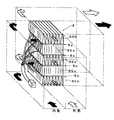
具体的には、外気がペルチェ素子複合体8の図8中紙面手前側から奥側に流れ、内気がペルチェ素子複合体8の図8中右側から左側へ流れるものであり、吸熱側のフィン86aと放熱側のフィン86bを、交互に、かつ、互いに直交するように配置している。つまり、あるモジュール構造8aの吸熱側のフィン86aを、そのモジュール構造8aに隣接するモジュール構造8aの吸熱側のフィン86aと共有させており、このようにして、モジュール構造8aを例えば4個積層している。
【0050】
この結果、図8中右側から左側へ流れる内気は、吸熱側のフィン86aを通過して吸熱、除湿され、図8中紙面手前側から奥側に流れる外気は、放熱側のフィン86bを通過して加熱される。
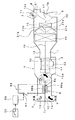
そして、図9に、本実施形態のペルチェ素子複合体8を内蔵するケース1を示す。図9において、紙面上下方向が、実際の上下方向と一致しており、100はエンジンルームと車室内とを仕切る仕切り板であり、第1、第2空気通路11、12は、紙面奥側で紙面右側へ屈曲して、車室内へ空調風を導くようになっている。
【0051】
このケース1には、第1、第2内気導入口31、32に加えて第3内気導入口33が形成され、さらに、ケース1内には、内気および外気のほこりや悪臭を除去するための、ひだおり加工したフィルタ101が配設されている。また、ペルチェ素子複合体8の凝縮水の排出口1cも形成されている。
外気導入口2および第2内気導入口32には、これら外気、第2内気導入口2、32を開閉するための開閉ドア2a、32aが設けられ、ペルチェ素子複合体8の下流側には、ペルチェ素子複合体8通過後の空気の通路としての開口部80が設けられ、この開口部80にも開閉ドア80aが設けられている。さらに、外気導入口2と第3内気導入口33との間には内外気切替ドア9が配設されている。
【0052】
そして、フットモードおよびフットデフモードにおいては、ペルチェ素子複合体8を作動させ、開閉ドア2aにて外気導入口2を開き、内外気切替ドア9にて第3内気導入口33を閉じ、開閉ドア80aにて開口部80を開いて、第2空気通路12に、除湿された内気と、加熱された外気とを導入する。
また、暖房が必要でないときは、ペルチェ素子複合体8は作動させず、開閉ドア2aにて外気導入口2を閉じ、内外気切替ドア9にて第3内気導入口33を開き、開閉ドア80aにて開口部80を閉じて、上記除湿および加熱を行わない。
【0053】
ここで、外気の温度が非常に低い場合(−20℃程度)、ペルチェ素子複合体8の放熱側のフィン86b(図8参照)からの放熱量が非常に大きくなり、これに伴って吸熱側のフィン86a(図8参照)における吸熱量も非常に大きくなって、吸熱側のフィン86aに付着する凝縮水が凍結する恐れがある。
これに対して、ペルチェ素子複合体8の吸熱側のフィン86aに、図示しない温度センサを設け、この温度センサの検出温度が、凝縮水の凍結温度、例えば−3℃程度になると、外気導入口2を閉じる方向に開閉ドア2aを移動させ、外気導入量を減少させる。これにより、ペルチェ素子複合体8の放熱側における放熱量が低下し、これに伴って吸熱側の吸熱量が低下して、吸熱側のフィン86aの温度が上昇するので、凝縮水の凍結を防止できる。
【0054】
また、温度センサの検出温度が、凝縮水の凍結温度よりも十分高く、さらに除湿能力アップが可能な温度、例えば3℃程度になると、外気導入口2を開く方向に開閉ドア2aを移動させ、外気導入量を増加させる。これにより、吸熱側のフィン86aの温度が下がるので、さらに除湿能力をアップできる。
(他の実施形態)
上記第1の実施形態では、フットモードおよびフットデフモードのとき、ペルチェ素子複合体8を作動させて、第2空気通路12に内気および外気を導入していたが、本発明はこれに限定されることはなく、冬季のデフロスタモードのように、デフロスタ吹出口7から低湿で、しかも、より温かい空調風を吹き出すのが好ましい場合、ペルチェ素子複合体8を作動させて、第2空気通路12に内気および外気を導入してもよい。この結果、第2空気通路12に外気のみを導入するのに比べて、第2空気通路12内の空気の暖房負荷を低減させることができ、この空気をヒータコア22にて効率よく加熱できる。
【0055】
また、上記第1ないし第4の実施形態において、エバポレータ20が作動していないときで、かつ、デフロスタ吹出口7から低湿な空調風を吹き出す必要のあるとき、ペルチェ素子複合体8のスイッチ87をオン状態となるよう、制御装置89にて制御してもよい。
また、上記第5の実施形態では、モジュール構造8aを4個積層してペルチェ素子複合体8を形成しているが、本発明はこれに限定されることはなく、モジュール構造8aを1個でペルチェ素子複合体8を形成してもよいし、モジュール構造8aを5個以上積層してペルチェ素子複合体8を形成してもよい。
【0056】
また、上記第5の実施形態では、外気導入口2、外気案内路13、第1内気導入口31、および内気案内路14がケース1に一体に形成されているが、別体に形成してもよい。
また、上記実施形態では、内気案内路14と外気案内路13とが並向に、または直交して配置されていたが、内気案内路14と外気案内路13とが対向するように配置してもよい。
【0057】
また、上記実施形態のモジュール構造8a(図2(b)参照)において、吸熱側と放熱側との間の空間に、吸熱側と放熱側とを断熱するための断熱部材を設けてもよい。この断熱部材は、熱伝導性の悪い材料、例えばウレタンフォーム等にて形成する。これにより、吸熱側と放熱側との間における、吸熱側と放熱側との熱の授受を防止でき、吸熱側と放熱側との温度差が小さくなるのを防止できる。
【図面の簡単な説明】
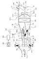
【図1】本発明の第1の実施形態を示す車両用空調装置の模式的な断面図である。
【図2】(a)はペルチェ素子のモジュール構造を示す斜視図、(b)はペルチェ素子複合体の1ユニットを示す斜視図である。
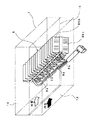
【図3】ペルチェ素子複合体の取付構造を示す斜視図である。
【図4】ペルチェ素子のモジュール構造の成績係数を示すグラフである。
【図5】本発明の第2の実施形態を示す車両用空調装置の模式的な断面図である。
【図6】本発明の第3の実施形態を示す車両用空調装置の模式的な断面図である。
【図7】本発明の第4の実施形態を示す車両用空調装置の模式的な断面図である。
【図8】本発明の第5の実施形態におけるペルチェ素子複合体の取付構造を示す斜視図である。
【図9】本発明の第5の実施形態を示す車両用空調装置の模式的な断面図である。
【符号の説明】
2…外気導入口、31…第1内気導入口、32…第2内気導入口、
4…送風機(送風手段)、5…フット吹出口、7…デフロスタ吹出口、
8…ペルチェ素子(電気素子)、13…外気案内路、14…内気案内路、
22…ヒータコア(暖房用熱交換器)。[0001]
BACKGROUND OF THE INVENTION
The present invention relates to a vehicle air conditioner that can heat a room, and is particularly suitable for use in a diesel vehicle, a hybrid vehicle, or the like in which a heat source is difficult to obtain.
[0002]
[Prior art]
2. Description of the Related Art In recent years, various types of vehicle air conditioners have improved heating performance by reducing the introduction amount of outside air having a larger ventilation load and heating load and increasing the introduction amount of a smaller ventilation air and a smaller heating air during heating. Proposed. However, there is a problem that the windshield is fogged due to the introduction of higher humidity inside air. On the other hand, in the vehicle air conditioner proposed in Japanese Patent Laid-Open No. 6-143996, heating is performed while keeping the antifogging property by dehumidifying the inside air.
[0003]
Specifically, a first air passage into which the inside air is introduced and a second air passage into which the outside air is introduced are partitioned in the case of the vehicle air conditioner, and the first and second air Inside air and outside air in the passage are respectively introduced into the passenger compartment. The inside air introduction amount into the first air passage and the outside air introduction amount into the second air passage are adjusted by changing the air amount of the blower provided on the air upstream side of each of the first and second air passages. .
[0004]
A heat pipe is provided across the first air passage and the second air passage. Here, the heat pipe circulates a heat medium inside, the heat medium absorbs the heat of the inside air on the inside air side, and releases the heat absorbed by the inside air to the outside air on the outside air side. The dehumidifying capacity of this heat pipe is determined by the temperature difference between the inside air temperature and the outside air temperature. Then, in accordance with the dehumidifying capacity of the heat pipe, the amount of inside air introduced in consideration of the anti-fogging property of the windshield is determined.
[0005]
[Problems to be solved by the invention]
However, in the above prior art, the inside air temperature and the outside air temperature cannot be artificially changed, so that a sufficient temperature difference between the inside air temperature and the outside air temperature cannot be taken. Therefore, a sufficient dehumidifying capacity cannot be obtained with a heat pipe, and it is difficult to sufficiently increase the introduction ratio of the inside air with respect to the total air introduction amount. That is, the conventional vehicle air conditioner has a problem that the heating performance cannot be effectively improved.
[0006]
The present invention has been made in view of the above points, and an object thereof is to effectively increase the heating performance by increasing the introduction amount of the inside air while maintaining the antifogging property.
[0007]
[Means for Solving the Problems]
In order to achieve the above object, the present invention employs the following technical means.
[0008]
Even if the temperature difference between the outside air temperature and the inside air temperature is small, the electric element (8) exhibits a sufficient dehumidifying capacity on the heat absorption side of the electric element (8) by adjusting the amount of electrical conduction. be able to. Therefore, it is possible to effectively absorb the heat from the inside air with relatively high humidity and cool and dehumidify the inside air, and the conditioned air composed of the inside air after dehumidification and the outside air with relatively low humidity is sent to the defroster outlet. By blowing out from (7), the anti-fogging property of the windshield can be achieved.
[0009]
Further, heat absorption from the inside air in the inside air guide path (14) by the electric element (8) increases the heating load of the inside air. On the other hand, the outside air guide path ( 13) Heating load of outside air is reduced by dissipating heat to the outside air. Therefore, in the case (1), the increase in the heating load on the inside air side can be offset by the reduction in the heating load on the outside air side.
[0010]
On the other hand, since this electric element (8) can sufficiently exhibit the dehumidifying ability, it is possible to effectively dehumidify the inside air and sufficiently increase the amount of inside air introduced into the case (1). Since the inside air has a smaller ventilation load and heating load than the outside air, the heating performance can be effectively enhanced by sufficiently increasing the inside air introduction amount.
By the way, when conditioned air is blown from both the defroster outlet (7) and the foot outlet (5), the conditioned air blown from the defroster outlet (7) has low humidity in order to achieve anti-fogging properties of the windshield. The air-conditioning air blown out from the foot outlet (5) is blown out to the feet of the occupant, and therefore does not need to be so low in humidity.
[0011]
Therefore, paying attention to this point, in the inventions according to
[0012]
Therefore, when the conditioned air is blown out from both the defroster outlet (7) and the foot outlet (5), it is necessary to form the low-humidity conditioned air from the inside air having a small heating load efficiently dehumidified by the electric element (8). The inside air that has not been dehumidified from the inside air inlets (31, 32, 3) can be introduced into the first air passage (12).
[0013]
That is, the defogging property of the windshield can be achieved by forming the conditioned air composed of the inside air after dehumidification and the outside air with relatively little moisture on the second air passage (12) side. In addition, the introduction amount of the inside air into the case (1) of the vehicle air conditioner can be reduced by introducing only the inside air having a smaller ventilation load and heating load than the outside air into the first air passage (11) side. It can increase more and can improve heating performance more effectively.
[0014]
[0015]
DETAILED DESCRIPTION OF THE INVENTION
Hereinafter, embodiments of the present invention will be described with reference to the drawings.
(First embodiment)
The vehicle air conditioner of the first embodiment is mounted on, for example, a diesel vehicle on which a diesel engine is mounted. Since a diesel engine generally has a smaller calorific value than a gasoline engine, it is difficult to obtain sufficient heating capacity in winter.
[0016]
Hereinafter, the schematic configuration of the vehicle air conditioner of the present embodiment will be described with reference to FIG. FIG. 1 is a schematic cross-sectional view of a vehicle air conditioner, and the front side of the page coincides with the upward direction of the vehicle.
The vehicle air conditioner includes a
[0017]
In the inside of the
The
[0018]
The first and second inside / outside
[0019]
And the
[0020]
The
And the
[0021]
Then, the air volume ratio sent to the
[0022]
Further, a
[0023]
In addition, an instrument panel (not shown) provided on the front surface of the passenger compartment has an operation unit of an air conditioner, and a blow
[0024]
Then, when the output signal of the blow
In addition, the on / off state of the
[0025]
Next, the structure of the Peltier element
First, as shown in FIG. 2A, a
[0026]
Then, as shown in FIG. 2B, the
A thin film (not shown) made of a material having excellent thermal conductivity, such as silver or silicon, is formed on the surfaces of the
[0027]
When a current is passed through the
Here, since the
[0028]
In FIG. 3, the
[0029]
Next, the operation of the present embodiment having the above configuration will be described.
In FIG. 1, when the foot mode is selected by the blowing
[0030]
Further, at the same time that the
[0031]
And the heat of the relatively humid inside air in the inside
[0032]
Then, in the vicinity of the heat
[0033]
Here, FIG. 4 shows the theoretical coefficient of performance COP (= Q / W, Q: amount of heat transferred from the heat absorption side to the heat dissipation side of the Peltier element, and W: input power to the Peltier element. ) (Reference: Junichi Uemura, Yoshio Nishida, Thermoelectric Semiconductor and its application, Nikkan Kogyo Shimbun). In this graph, the horizontal axis is the temperature difference between the temperature on the heat dissipation side and the temperature on the heat absorption side of the
[0034]
As described above, the heat dissipation side of the
[0035]
The inventors have confirmed that the temperature difference is about 0 to 10 ° C. when the input power to the
[0036]
Therefore, even if the temperature difference between the inside air and the outside air is small, the dehumidifying ability can be sufficiently exerted on the heat absorption side of the
[0037]
In addition, heat absorption from the inside air in the inside
On the other hand, since the
[0038]
Moreover, since the input power of the Peltier element
In the above operation, the case where the
[0039]
In addition, in the face mode, bi-level mode, and defroster mode, when it is necessary to blow out low-humidity conditioned air from the
[0040]
(Second Embodiment)
In 2nd Embodiment, as shown in FIG. 5, 1st partition member 10 'said by the said 1st Embodiment is an evaporator from on the boundary line of the
[0041]
In the foot mode, as shown in FIG. 5, the first and second inside / outside
[0042]
The inside air is cooled and dehumidified by the heat
According to the second embodiment, similarly to the first embodiment, the amount of inside air introduced into the
[0043]
Further, by disposing the
(Third embodiment)
In the third embodiment, as shown in FIG. 6, one end 1a of the
[0044]
In the foot mode, as shown in FIG. 6, the inside air is introduced into the inside
[0045]
According to the third embodiment, similarly to the first embodiment, the amount of inside air introduced into the
(Fourth embodiment)
In the third embodiment, the
[0046]
In the foot mode, as shown in FIG. 7, the inside air is introduced into the inside
[0047]
According to the fourth embodiment, in the vehicle air conditioner in which the inside of the
[0048]
(Fifth embodiment)
In the first to fourth embodiments, the inside
[0049]
Specifically, the outside air flows from the front side of the
[0050]
As a result, the inside air flowing from the right side to the left side in FIG. 8 passes through the heat-absorbing
FIG. 9 shows a
[0051]
In this
The outside
[0052]
In the foot mode and the foot differential mode, the
When heating is not required, the
[0053]
Here, when the temperature of the outside air is very low (about −20 ° C.), the amount of heat released from the
On the other hand, when a temperature sensor (not shown) is provided on the
[0054]
In addition, when the temperature detected by the temperature sensor is sufficiently higher than the freezing temperature of the condensed water and further increases the dehumidifying capacity, for example, about 3 ° C., the open /
(Other embodiments)
In the first embodiment, in the foot mode and the foot differential mode, the
[0055]
In the first to fourth embodiments, the
In the fifth embodiment, four
[0056]
In the fifth embodiment, the outside
In the above embodiment, the inside
[0057]
In the
[Brief description of the drawings]
FIG. 1 is a schematic cross-sectional view of a vehicle air conditioner showing a first embodiment of the present invention.
FIG. 2A is a perspective view showing a module structure of a Peltier element, and FIG. 2B is a perspective view showing one unit of a Peltier element complex.
FIG. 3 is a perspective view showing a mounting structure of a Peltier element composite.
FIG. 4 is a graph showing a coefficient of performance of a module structure of a Peltier element.
FIG. 5 is a schematic cross-sectional view of a vehicle air conditioner showing a second embodiment of the present invention.
FIG. 6 is a schematic cross-sectional view of a vehicle air conditioner showing a third embodiment of the present invention.
FIG. 7 is a schematic cross-sectional view of a vehicle air conditioner showing a fourth embodiment of the present invention.
FIG. 8 is a perspective view showing a mounting structure for a Peltier element composite according to a fifth embodiment of the present invention.
FIG. 9 is a schematic cross-sectional view of a vehicle air conditioner showing a fifth embodiment of the present invention.
[Explanation of symbols]
2 ... Outside air introduction port, 31 ... First inside air introduction port, 32 ... Second inside air introduction port,
4 ... Blower (blower means), 5 ... Foot outlet, 7 ... Defroster outlet,
8 ... Peltier element (electric element), 13 ... Outside air guideway, 14 ... Inside air guideway,
22 ... Heater core (heat exchanger for heating).
Claims (4)
前記ケース(1)内に配設され、前記一端(1a)から前記他端(1b)に向かう空気流を発生させる送風手段(4)と、
前記ケース(1)内に形成され、少なくとも外気導入口(2)からの外気を前記他端(1b)側へ導入する外気案内路(13)と、
前記ケース(1)内の前記外気案内路(13)近傍に形成され、少なくとも内気導入口(31、32、3)からの内気を前記他端(1b)側へ導入する内気案内路(14)と、
前記内気案内路(14)および前記外気案内路(13)の空気下流側に配設され、前記ケース(1)内の空気を加熱する暖房用熱交換器(22)と、
前記外気案内路(13)および前記内気案内路(14)の近傍に配設され、電気的に通電されて前記内気案内路(14)を流通する内気から吸熱し、かつ、前記外気案内路(13)を流通する外気に放熱する電気素子(8)とを備え、
前記外気案内路(13)と前記内気案内路(14)とを区画形成する仕切り部材(10’)が設けられており、この仕切り部材(10’)に前記電気素子(8)が配設されていることを特徴とする車両用空調装置。One end (1a) is provided with an outside air introduction port (2) for introducing outside air and an inside air introduction port (31, 32, 3) for introducing inside air, and the other end (1b) is air-conditioned on the inner surface of the windshield. A case (1) provided with at least a defroster outlet (7) for blowing air and a foot outlet (5) for blowing air-conditioned air to the feet of the occupant;
A blowing means (4) disposed in the case (1) and generating an air flow from the one end (1a) toward the other end (1b);
An outside air guide path (13) formed in the case (1) and introducing at least outside air from the outside air inlet (2) to the other end (1b) side;
An inside air guide path (14) formed near the outside air guide path (13) in the case (1) and introducing at least inside air from the inside air introduction ports (31, 32, 3) to the other end (1b) side. When,
A heating heat exchanger (22) that is disposed on the air downstream side of the inside air guide path (14) and the outside air guide path (13) and heats the air in the case (1);
It is disposed in the vicinity of the outside air guide path (13) and the inside air guide path (14), is electrically energized and absorbs heat from the inside air flowing through the inside air guide path (14), and the outside air guide path ( And 13) an electric element (8) that radiates heat to the outside air that circulates ,
A partition member (10 ′) that partitions the outside air guide path (13) and the inside air guide path (14) is provided, and the electric element (8) is disposed in the partition member (10 ′). the vehicle air-conditioning system, characterized in that are.
前記ケース(1)内に形成され、一端には少なくとも前記内気導入口(32、3)からの内気が導入され、他端は前記フット吹出口(5)に連通する第1空気通路(11)と、
前記ケース(1)内に形成され、一端には前記内気案内路(14)からの内気および前記外気案内路(13)からの外気が少なくとも導入され、他端は前記デフロスタ吹出口(7)に連通する第2空気通路(12)と、
前記第1空気通路(11)と前記第2空気通路(12)とを区画形成する仕切り部材(10)とを備え、
前記暖房用熱交換器(22)は、前記第1、第2空気通路(11、12)内に配設され、この第1、第2空気通路(11、12)内の空調風を加熱することを特徴とする車両用空調装置。In the vehicle air conditioner according to claim 1,
A first air passage (11) formed in the case (1), at least one inside air from the inside air inlet (32, 3) is introduced into one end and the other end communicates with the foot outlet (5). When,
Formed in the case (1), at least one of the inside air from the inside air guide passage (14) and the outside air from the outside air guide passage (13) is introduced into one end, and the other end is connected to the defroster outlet (7). A second air passage (12) in communication;
A partition member (10) for partitioning and forming the first air passage (11) and the second air passage (12);
The heating heat exchanger (22) is disposed in the first and second air passages (11, 12), and heats the conditioned air in the first and second air passages (11, 12). An air conditioner for a vehicle.
前記内気導入口は、第1内気導入口(31)および第2内気導入口(32)からなり、
前記内気案内路(14)は、少なくとも前記第1内気導入口(31)からの内気を前記他端(1b)側へ導入するように構成され、
前記ケース(1)内に形成され、一端には少なくとも前記第2内気導入口(32)からの内気が導入され、他端は前記フット吹出口(5)に連通する第1空気通路(11)と、
前記ケース(1)内に形成され、一端には前記内気案内路(14)からの内気および前記外気案内路(13)からの外気が少なくとも導入され、他端は前記デフロスタ吹出口(7)に連通する第2空気通路(12)と、
前記第1空気通路(11)と前記第2空気通路(12)とを区画形成する仕切り部材(10)とを備え、
前記暖房用熱交換器(22)は、前記第1、第2空気通路(11、12)内に配設され、この第1、第2空気通路(11、12)内の空調風を加熱することを特徴とする車両用空調装置。In the vehicle air conditioner according to claim 1,
The inside air introduction port includes a first inside air introduction port (31) and a second inside air introduction port (32),
The inside air guide path (14) is configured to introduce at least inside air from the first inside air introduction port (31) to the other end (1b) side,
A first air passage (11) formed in the case (1), having at least one inside air introduced from the second inside air introduction port (32) at one end and communicating with the foot outlet (5) at the other end. When,
Formed in the case (1), at least one of the inside air from the inside air guide passage (14) and the outside air from the outside air guide passage (13) is introduced into one end, and the other end is connected to the defroster outlet (7). A second air passage (12) in communication;
A partition member (10) for partitioning and forming the first air passage (11) and the second air passage (12);
The heating heat exchanger (22) is disposed in the first and second air passages (11, 12), and heats the conditioned air in the first and second air passages (11, 12). An air conditioner for a vehicle.
この判定手段(89)にて前記条件を判定したとき、前記電気素子(8)を作動させることを特徴とする請求項1ないし3のいずれか1つに記載の車両用空気調和装置。A determination means (89) for determining a condition for blowing low-humidity conditioned air from the defroster outlet (7);
The vehicle air conditioner according to any one of claims 1 to 3 , wherein when the condition is determined by the determination means (89), the electric element (8) is operated.
Priority Applications (3)
| Application Number | Priority Date | Filing Date | Title |
|---|---|---|---|
| JP03240996A JP3675017B2 (en) | 1996-01-16 | 1996-02-20 | Air conditioner for vehicles |
| DE19651279A DE19651279B4 (en) | 1995-12-13 | 1996-12-10 | Air conditioning for a vehicle |
| US08/763,357 US6213198B1 (en) | 1995-12-13 | 1996-12-11 | Air conditioning apparatus for vehicle with thermoelectric dehumidifier in a double layer system |
Applications Claiming Priority (3)
| Application Number | Priority Date | Filing Date | Title |
|---|---|---|---|
| JP8-4964 | 1996-01-16 | ||
| JP496496 | 1996-01-16 | ||
| JP03240996A JP3675017B2 (en) | 1996-01-16 | 1996-02-20 | Air conditioner for vehicles |
Publications (2)
| Publication Number | Publication Date |
|---|---|
| JPH09254630A JPH09254630A (en) | 1997-09-30 |
| JP3675017B2 true JP3675017B2 (en) | 2005-07-27 |
Family
ID=26338837
Family Applications (1)
| Application Number | Title | Priority Date | Filing Date |
|---|---|---|---|
| JP03240996A Expired - Fee Related JP3675017B2 (en) | 1995-12-13 | 1996-02-20 | Air conditioner for vehicles |
Country Status (1)
| Country | Link |
|---|---|
| JP (1) | JP3675017B2 (en) |
Cited By (1)
| Publication number | Priority date | Publication date | Assignee | Title |
|---|---|---|---|---|
| KR101510001B1 (en) * | 2013-12-04 | 2015-04-07 | 현대자동차주식회사 | Heater core apparatus for vehicle |
Families Citing this family (23)
| Publication number | Priority date | Publication date | Assignee | Title |
|---|---|---|---|---|
| KR100601835B1 (en) * | 1999-12-30 | 2006-07-19 | 한라공조주식회사 | Automotive Air Conditioning Equipment |
| US7231772B2 (en) * | 2001-02-09 | 2007-06-19 | Bsst Llc. | Compact, high-efficiency thermoelectric systems |
| US7380586B2 (en) | 2004-05-10 | 2008-06-03 | Bsst Llc | Climate control system for hybrid vehicles using thermoelectric devices |
| US7743614B2 (en) | 2005-04-08 | 2010-06-29 | Bsst Llc | Thermoelectric-based heating and cooling system |
| CN101213679B (en) | 2005-06-28 | 2010-09-29 | Bsst有限责任公司 | Thermoelectric Generators for Variable Thermal Power Sources |
| US20100155018A1 (en) | 2008-12-19 | 2010-06-24 | Lakhi Nandlal Goenka | Hvac system for a hybrid vehicle |
| JP2008087636A (en) * | 2006-10-02 | 2008-04-17 | Calsonic Kansei Corp | Air conditioner |
| WO2008148042A2 (en) | 2007-05-25 | 2008-12-04 | Bsst Llc | System and method for distributed thermoelectric heating and colling |
| US8701422B2 (en) | 2008-06-03 | 2014-04-22 | Bsst Llc | Thermoelectric heat pump |
| US9555686B2 (en) | 2008-10-23 | 2017-01-31 | Gentherm Incorporated | Temperature control systems with thermoelectric devices |
| US9447994B2 (en) | 2008-10-23 | 2016-09-20 | Gentherm Incorporated | Temperature control systems with thermoelectric devices |
| KR102112970B1 (en) | 2009-05-18 | 2020-05-19 | 젠썸 인코포레이티드 | Battery thermal management system |
| CN104914896B (en) | 2009-05-18 | 2017-06-13 | 詹思姆公司 | temperature control system with thermoelectric device |
| JP5577661B2 (en) * | 2009-09-28 | 2014-08-27 | カルソニックカンセイ株式会社 | Air conditioner for vehicles |
| KR101571905B1 (en) | 2010-10-04 | 2015-11-26 | 현대자동차주식회사 | Sub air conditioner for vehicles |
| KR101605916B1 (en) | 2010-11-01 | 2016-03-23 | 현대자동차주식회사 | A cooling and heating device of electric vehicle |
| JP6281362B2 (en) | 2014-03-26 | 2018-02-21 | 株式会社デンソー | Air conditioning unit for vehicles |
| JP6221890B2 (en) | 2014-03-26 | 2017-11-01 | 株式会社デンソー | Air conditioning unit for vehicles |
| CN107249910B (en) | 2014-12-19 | 2021-01-15 | 詹思姆公司 | Thermal conditioning system and method for a vehicle area |
| JP6468348B2 (en) | 2015-04-24 | 2019-02-13 | 株式会社デンソー | Anti-fogging device for vehicles |
| WO2017065847A1 (en) | 2015-10-14 | 2017-04-20 | Gentherm Incorporated | Systems and methods for controlling thermal conditioning of vehicle regions |
| CN121230238A (en) | 2018-11-30 | 2025-12-30 | 金瑟姆股份公司 | Thermoelectric control systems and methods |
| KR102738069B1 (en) * | 2019-10-22 | 2024-12-05 | 한온시스템 주식회사 | Contact type air conditioner for vehicle |
-
1996
- 1996-02-20 JP JP03240996A patent/JP3675017B2/en not_active Expired - Fee Related
Cited By (1)
| Publication number | Priority date | Publication date | Assignee | Title |
|---|---|---|---|---|
| KR101510001B1 (en) * | 2013-12-04 | 2015-04-07 | 현대자동차주식회사 | Heater core apparatus for vehicle |
Also Published As
| Publication number | Publication date |
|---|---|
| JPH09254630A (en) | 1997-09-30 |
Similar Documents
| Publication | Publication Date | Title |
|---|---|---|
| JP3675017B2 (en) | Air conditioner for vehicles | |
| US6213198B1 (en) | Air conditioning apparatus for vehicle with thermoelectric dehumidifier in a double layer system | |
| US6205805B1 (en) | Motor vehicle dehumidifier with drying agent and drying agent regenerative control | |
| CA1321476C (en) | Automotive air conditioning system | |
| JP2001010327A (en) | Vehicle air conditioner | |
| JP2010076506A (en) | Air conditioner for vehicle | |
| JP2009274587A (en) | Dehumidifying and humidifying device for vehicle | |
| JP4539343B2 (en) | Air conditioner | |
| JP3893661B2 (en) | Air conditioner for vehicles | |
| KR101403441B1 (en) | A cooling and heating device of rear seat for vehicles using thermoelectric element | |
| US10675951B2 (en) | Humidifying device | |
| JP3900592B2 (en) | Air conditioner for vehicles | |
| JPH1016531A (en) | Vehicle air conditioner | |
| JP4538846B2 (en) | Air conditioner | |
| JP3692626B2 (en) | Air conditioner for vehicles | |
| JP3799647B2 (en) | Automotive air conditioner | |
| JP4134407B2 (en) | Air conditioner for vehicles | |
| JP2009280149A (en) | Dehumidification/humidification device for vehicle | |
| JP3772471B2 (en) | Air conditioner for vehicles | |
| JP4078743B2 (en) | Air conditioner for vehicles | |
| JP3975541B2 (en) | Air conditioner for vehicles | |
| JP2000318442A (en) | Air conditioner for vehicle | |
| JPH11222027A (en) | Air conditioner for electric vehicle | |
| JPH1058939A (en) | Air conditioner for automobile | |
| CN219096445U (en) | Air conditioning device, air conditioning system and vehicle |
Legal Events
| Date | Code | Title | Description |
|---|---|---|---|
| A977 | Report on retrieval |
Free format text: JAPANESE INTERMEDIATE CODE: A971007 Effective date: 20041217 |
|
| A131 | Notification of reasons for refusal |
Free format text: JAPANESE INTERMEDIATE CODE: A131 Effective date: 20050111 |
|
| A521 | Written amendment |
Free format text: JAPANESE INTERMEDIATE CODE: A523 Effective date: 20050307 |
|
| TRDD | Decision of grant or rejection written | ||
| A01 | Written decision to grant a patent or to grant a registration (utility model) |
Free format text: JAPANESE INTERMEDIATE CODE: A01 Effective date: 20050412 |
|
| A61 | First payment of annual fees (during grant procedure) |
Free format text: JAPANESE INTERMEDIATE CODE: A61 Effective date: 20050425 |
|
| R150 | Certificate of patent or registration of utility model |
Free format text: JAPANESE INTERMEDIATE CODE: R150 |
|
| FPAY | Renewal fee payment (event date is renewal date of database) |
Free format text: PAYMENT UNTIL: 20080513 Year of fee payment: 3 |
|
| FPAY | Renewal fee payment (event date is renewal date of database) |
Free format text: PAYMENT UNTIL: 20110513 Year of fee payment: 6 |
|
| FPAY | Renewal fee payment (event date is renewal date of database) |
Free format text: PAYMENT UNTIL: 20120513 Year of fee payment: 7 |
|
| FPAY | Renewal fee payment (event date is renewal date of database) |
Free format text: PAYMENT UNTIL: 20120513 Year of fee payment: 7 |
|
| FPAY | Renewal fee payment (event date is renewal date of database) |
Free format text: PAYMENT UNTIL: 20130513 Year of fee payment: 8 |
|
| FPAY | Renewal fee payment (event date is renewal date of database) |
Free format text: PAYMENT UNTIL: 20140513 Year of fee payment: 9 |
|
| LAPS | Cancellation because of no payment of annual fees |