JP3662230B2 - Support composed of aromatic polyester film and photographic light-sensitive material using the same - Google Patents
Support composed of aromatic polyester film and photographic light-sensitive material using the same Download PDFInfo
- Publication number
- JP3662230B2 JP3662230B2 JP2002167783A JP2002167783A JP3662230B2 JP 3662230 B2 JP3662230 B2 JP 3662230B2 JP 2002167783 A JP2002167783 A JP 2002167783A JP 2002167783 A JP2002167783 A JP 2002167783A JP 3662230 B2 JP3662230 B2 JP 3662230B2
- Authority
- JP
- Japan
- Prior art keywords
- aromatic polyester
- polyester film
- heat
- photographic light
- sensitive material
- Prior art date
- Legal status (The legal status is an assumption and is not a legal conclusion. Google has not performed a legal analysis and makes no representation as to the accuracy of the status listed.)
- Expired - Fee Related
Links
Landscapes
- Non-Silver Salt Photosensitive Materials And Non-Silver Salt Photography (AREA)
- Manufacture Of Macromolecular Shaped Articles (AREA)
- Processing And Handling Of Plastics And Other Materials For Molding In General (AREA)
Description
【0001】
【発明の属する技術分野】
本発明は芳香族系ポリエステルフィルムの支持体とそれを用いた写真感光材料に関する。
【0002】
【従来の技術】
従来写真感光材料は、撮影後現像液を用いて湿式現像を行っている。しかし、この方法では、下記のような不具合がありこの点の改善が望まれていた。
▲1▼現像、漂白、定着、乾燥を行なうため、現像処理に時間を要する。
▲2▼現像液を入れたタンクを複数個必要とするため、現像機を小型軽量化できない。
▲3▼現像液の補充、廃棄および現像タンクの洗浄等の手間を要する。
これを改善するために、米国特許第3152904号明細書、米国特許第3457075号明細書、特公昭43−4921号公報、特公昭43−4924号公報等に記載されているような80〜150℃の熱による現像方法(以下熱現像と略することがある)で処理する写真感材が提唱される。この一つの例として感光層中にあらかじめ現像薬の前駆体を含ませておき、これを熱により分解し現像薬とし、現像する方法等が挙げられる。このような熱現像方式では、現像処理は熱を与えるだけでよく短時間で処理が可能であり、現像機も小型化できる。さらに現像液の補充や廃棄の心配が無い。
しかし印刷用感材にこの方式の感材を用いた場合、熱現像中に発生する寸法変化のために、4版(青、緑、赤、墨版)を重ねた場合、色ずれが発生するという難点がある。これを解決するために、従来低張力下で写真用支持体を熱処理する方法が知られている(例えば、特開昭60−22616号公報、特開昭64−64883号公報、特開昭54−158470号公報、米国特許第2779684号明細書)。これらの低張力熱処理を施すことで熱現像前後の寸法変化は小さくすることはできたが、これに伴い平面性不良(縦皺故障:支持体の長手方向に皺の山が屋根状に続き、幅方向に10〜20cmピッチで発生する皺)が発生し、高い平面性が必要とされる写真用支持体にとって大きな問題であった。この対策として、米国特許第3663683号明細書に記載されているような多数のロール間を通過させロール上で皺を伸ばす方法が知られている。しかしこの方法ではパスロールで発生する張力ロスが大きく低張力で搬送しにくく十分な寸法安定性を達成できなかった。
【0003】
【発明が解決しようとする課題】
本発明は平面性が良好であり熱寸法安定性にすぐれた芳香族系ポリエステルフィルムからなるハロゲン化銀写真用支持体とそれを用いたハロゲン化銀写真感光材料を提供することである。
【0004】
【課題を解決するための手段】
これらの課題は下記の手段により達成された。
すなわち本発明は
(1) 150℃熱収縮が0.01%以上0.4%以下である芳香族系ポリエステルフイルムを、下記式(1)〜(3)を同時に満足する条件で搬送しながら熱処理され、かつ縦皺高さが0μm以上200μm以下、120℃での長手方向熱収縮が0.001%以上0.05%以下であることを特徴とする芳香族系ポリエステルフィルムからなる、ハロゲン化銀写真感光材料の支持体。
0.001≦F≦0.05 (1)
120≦T≦220 (2)
1≦(T×L)/(F×1000)≦800 (3)
F=熱可塑性フィルムに加わる単位断面積当りの搬送張
力(kg/mm 2 )
T=熱処理温度(℃)
L=熱処理ゾーン中の最長非接触搬送長(m)
(2) 十点平均粗さ(Rz)が0.18μm以上8.0μm以下、最大点高さ(Rt)が0.3μm以上10μm以下である芳香族系ポリエステルフィルムを前記熱処理して得られた(1)に記載の芳香族系ポリエステルフィルムからなる、ハロゲン化銀写真感光材料の支持体。
(3) マット剤を含有する下塗り層およびバッキング層を有する芳香族系ポリエステルフィルムであって、縦皺高さが0μm以上200μm以下、120℃での長手方向熱収縮が0.001%以上0.05%以下であることを特徴とする芳香族系ポリエステルフィルムからなる、ハロゲン化銀写真感光材料の支持体。
(4) 前記マット剤の粒径が0.1〜15μmであることを特徴とする(3)に記載の芳香族系ポリエステルフィルムからなる、ハロゲン化銀写真感光材料の支持体。
(5) (1)〜(4)のいずれか1項に記載の芳香族系ポリエステルフィルムの支持体に用いたことを特徴とするハロゲン化銀写真感光材料。
(6) 熱現像写真感光材料であることを特徴とする(5)記載のハロゲン化銀写真感光材料。
【0005】
本発明は、上記縦皺故障が熱処理工程中に熱可塑性フィルムがロール間で収縮することで発生することを明らかにし成されたものである。即ち低張力で高温で熱処理を行なうと支持体は熱収縮しようとする。しかし、パスロール上ではフィルムとロールの摩擦力により収縮が抑制される。一方ロール間では自由に収縮できるため、フィルムの幅が小さくなる。このようなロール上とロール間の幅の差を解消するために、ロール近傍で波打が発生する。高温ではクリープし易く、このような変形が永久変形となる。従って、このような縦皺は高温でかつ低張力で搬送しているときに発生しやすい。
従って、縦皺は熱処理ゾーン中のパスロール間長、即ち非接触搬送長が長いほど発生しやすく、温度が高いほど、かつ張力が小さいほど発生しやすい。本発明方法ではこの縦皺の発生しない熱処理が行われる。
【0006】
【発明の実施の形態】
本発明において熱可塑性フィルムとして用いられる芳香族系ポリエステルフィルムの製造方法は次のとおりである。
(イ)下記式(1)〜(3)を同時に満足する条件で搬送しながら熱処理することにより製造することができる。
0.001≦F≦0.05 (1)
120≦T≦220 (2)
1≦(T×L)/(F×1000)≦800 (3)
F=熱可塑性フィルムに加わる単位断面積当りの搬送張力(kg/mm2 )
T=熱処理温度(℃)
L=熱処理ゾーン中の最長非接触搬送長(m)
(ロ)該熱可塑性フィルムの熱処理前の150℃熱収縮が0.01%以上0.4%以下であることを特徴として(イ)に記載の熱処理が行われ製造される。
(ハ)該熱可塑性フィルムの熱処理前の150℃熱収縮の幅方向分布の最大値と最小値の差が0%以上0.1%以下であることを特徴として(イ)又は(ロ)に記載の熱可塑性フィルムが製造される。
(ニ)熱処理前の熱可塑性フィルムの十点平均粗さ(Rz )が0.18μm以上8.0μm以下、最大点高さ(Rt )が0.3μm以上10μm以下であることを特徴として(イ)〜(ロ)に記載の熱処理方法が行われ、製造される。搬送張力Fは本発明の範囲を越えると熱収縮が大きくなりやすく好ましくない。一方本発明の範囲未満では蛇行等の搬送トラブルが発生しやすく好ましくない。搬送張力は通常0.001kg/mm2以上0.05kg/mm2以下、好ましくは0.003kg/mm2以上0.03kg/mm2以下、さらに好ましくは0.007kg/mm2以上0.02kg/mm2以下である。このような張力は巻き取り側、送り出し側の少なくとも一方に設置したモーターを調整することで達成できる。このときテンションピックアップを設置し、張力をモニターしながら調整するのが好ましい。但しこのような低張力で巻き取ると巻崩れ易いため、巻き取り部の前でテンションカットした後、高い張力で巻き取るのが好ましい。
【0007】
熱処理温度は通常120℃以上220℃以下、好ましくは135℃以上200℃以下であり、145℃以上180℃以下がさらに好ましい。この温度範囲を越えると熱可塑性フィルム中に含まれるオリゴマーが表面に析出しヘイズが上昇しやすく望ましくない。この温度範囲を下回ると熱収縮が大きくなりやすく発明の目的が達成できない。このような温度制御は断熱材を用いた熱処理ゾーン内に熱風を吹き込んで達成してもよく、ヒートロールのような高温の熱媒体に接触させて伝熱で可塑性フィルムを昇温してもよく、赤外線ヒーターのようなものを用いて輻射熱で昇温してもよい。いずれの方法でもよいが、幅方向の温度分布を小さくすることが熱収縮の幅方向分布を小さくするために好ましい。これには熱風の吹き出し口にフィンを設置し風の向きを調整することで吹き溜まりを無くしたり、温度の低くなりやすい両端部の温度が高くなるようにヒートロールや赤外線ヒーターを分割制御することで達成できる。ここで熱処理の温度Tはガラス転位温度Tg よりも高い温度である。
【0008】
パスロール間の最大長は、通常、張力(F)と熱処理温度(T)の関数として上記(3)式で示した1≦(T×L)/(F×1000)≦800の範囲であり、好ましくは2≦(T×L)/(F×1000)≦200、さらに好ましくは4≦(T×L)/(F×1000)≦80を満足するように設定するのが好ましい。この範囲を下回るとロール間隔が短く多数のパスロールを設置する必要があり、ここで発生する張力ロスのため搬送張力を大きく設定する必要があり、寸法安定性が悪化しやすい。一方この範囲を上回るとベース幅の収縮が大きくなりやすく縦皺が発生しやすく望ましくない。ここで云うパスロール間の長さは熱処理ゾーン中に存在する最大長さを指す。これは、1カ所でも本発明の範囲を越えるとそこで縦皺が発生するため、最大長さを上記範囲に入れる必要がある。パスロール間で一度発生した縦皺はなかなか消失しにくいため、この点が重要である。
【0009】
さらに本発明は用いる熱可塑性フィルムの改良で縦皺の問題をさらに軽減させることができる。その第1は熱処理前の熱可塑性フィルムの150℃熱収縮を0.01%以上0.4%以下にする。好ましくは0.05%以上0.3%以下、さらに好ましくは0.1%以上0.25%以下のものを用いることである。即ち熱収縮の小さな熱可塑性フィルムを用いることで、熱処理中に発生するパスロール間の収縮を小さくし、縦皺の発生を抑制する効果がある。熱収縮が0.4%を越えると、写真画像の寸度安定性が悪化する。一方150℃熱収縮が上記の範囲を下回る熱可塑性フィルムは十分熱寸法安定性が高く、本発明の熱処理を実施する必要が無い。このような支持体はa.延伸条件の改良、b.事前熱処理の方法が挙げられるがbの方法がより好ましい。bの方法は本発明の熱処理の前に120℃から220℃、より好ましくは130℃以上200℃以下、さらに好ましくは150℃以上190℃以下で熱処理する。これにより予めある程度熱収縮させておき、本発明の熱処理で発生する熱収縮量を小さくするものである。従ってこの事前熱処理は上記の熱処理のような高い寸法安定性を要求しないため、その分張力を上げることで縦皺を発生しないようにするほうが好ましい。このような熱処理は熱処理だけ単独で行ってもよいが、塗布工程がある場合はこの後の乾燥工程の中で実施するのが効率的である。写真用支持体として用いる場合は下塗、バッキング層を塗工するためこの乾燥工程で実施するのが好ましい。
一方aの方法は延伸倍率を小さくすること、熱固定温度を高くすることで達成できるが、いずれも熱可塑性フィルムの弾性率を小さくする方向であり、あまり好ましくない。
【0010】
次に熱可塑性フィルムの改良の第2は熱処理前の150℃熱収縮の幅方向分布の最大値と最小値の差が0%以上0.10以下、より好ましくは0%以上以上0.07%以下、さらに好ましくは0%以上0.05%以下の熱可塑性フィルムを用いるのが好ましい。即ち熱収縮が幅方向に均一な熱可塑性フィルムを用いるのが好ましい。これは、熱収縮量にムラがあると、局所的に大きく収縮し、そこから縦皺を発生しやすいためである。このような熱可塑性フィルムは▲1▼製膜条件の改良、▲2▼事前熱処理により達成できる。▲1▼は熱収縮の大きくなりやすい端部に対し熱固定温度を上げることで達成できる。▲2▼は上述の記載と同じものであり、熱収縮の絶対値を小さくすることで、最大値と最小値の差も小さくしようとするものである。
【0011】
さらに第3は熱可塑性フィルムの十点平均粗さ(Rz)を0.18μm以上8.0μm以下にするのが好ましく、より好ましくは0.20μm以上6.0μm以下、さらに好ましくは0.3μm以上4.5μm以下である。Rzは基準長さのなかに存在する山の高さのなかの高いものから10点の平均値と、谷の深さの深いものから10点の平均値の差を指す。即ち平均的な凹凸(平均粗さ;Ra)よりも大きな突起の高さを本発明の範囲にすると有効にロールと熱可塑性フィルムの間の摩擦を下げることができる。さらにこれと同様の理由で最大点高さ(Rt)を0.3μm以上10.0μm以下、より好ましくは0.4μm以上8.0μm以下、さらに好ましくは0.6μm以上6.0μm以下にするのが好ましい。Rtは基準長さの中に存在する最高突起と最深谷との差を指す。Rz、Rtとも本発明の範囲を下回ると平面性が低下し易く、上回ると添加した微粒子が剥落しロール汚れを引き起こし好ましくない。
【0012】
このような熱可塑性フィルムは熱可塑性フィルムの表面に凹凸を付与することでパスロールとの摩擦を調整し、パスロール上でも熱収縮し易くするものである。これにより拘束力を受けていないパスロール間の熱可塑性フィルムと同様に収縮できるため、縦皺の発生を軽減させることができる。本発明の範囲を越えると表面粗さ達成のために添加した微粒子が剥落し、工程を汚染し好ましくない。一方下回ると効果が得られず縦皺が発生しやすい。このような熱可塑性フィルムは、▲1▼微粒子層を最表面に付与する、▲2▼熱可塑性フィルム中に添加する微粒子(フィラー)の増量で対応できる。
【0013】
▲1▼の方法は、シリカ、アルミナ、硫酸バリウム、炭酸カルシウム、チタニア、酸化スズ、酸化インジウム、タルクのような無機物、あるいはポリスチレン、ポリメチルメタクリレート、ポリメタクリレート、ポリアクリロニトリル、セルロース、ゼラチン等の有機微粒子をバインダーと一緒に塗設する方法が挙げられる。これらの微粒子の形状は特に制限がなく、針状でも、球形でも、板状でも破砕状でも用いることができる。好ましい大きさは0.1〜15μm、より好ましくは0.2〜10μm、さらに好ましくは0.3〜7μmである。マット剤の添加量は片面1m2あたり0.1〜50mg、より好ましくは0.2〜30mg、さらに好ましくは0.3〜20mgである。これらの微粒子の中でも特に好ましいのがZnO、TiO2、SnO2、Al2O3、In2O3、SiO2、MgO、BaO、MoO3、V2O5の中から選ばれた少なくとも1種の結晶性の金属酸化物或いはこれらの複合酸化物の微粒子である。さらに好ましい物は、SnO2を主成分とし酸化アンチモン約5〜20%含有させ及び/又はさらに他成分(例えば酸化珪素、ホウ素、リンなど)を含有させた導電性材料である。これらの導電性微粒子を用いると熱処理の間に発生する静電気によるゴミ付き故障を抑制できる。これらの導電性の無機微粒子はその体積抵抗率が107Ωcm以下、より好ましくは106Ωcm以下、さらに好ましくは105Ωcm以下である。これらの微粒子を分散するバインダーとしては特に制限は無く、ゼラチン、水溶性ポリエステル、ポリウレタン、スチレン−ブタジエンゴム、ポリ塩化ビニリデン、ポリ塩化ビニル、ポリウレタン、ポリアクリルエステル、ポリメタクリルエステル、ポリアミド等を用いることができる。
【0014】
これらの塗布に先だって接着性向上のためにグロー放電処理、コロナ処理、紫外線処理、火炎処理を実施することも好ましい。またこれらの塗布は公知の方法を用いることができる。例えばディップコート法、エアーナイフコート法、カーテンコート法、ローラーコート法、ワイヤーバーコート法、グラビアコート法、或いは、米国特許第2681294号記載のホッパーを使用するエクストルージョンコート法、又は米国特許第2761418号明細書、同3508947号明細書、同2761791号明細書記載の多層同時塗布方法を用いることができる。
【0015】
▲2▼の方法はシリカ、アルミナ、硫酸バリウム、炭酸カルシウム、チタニア、酸化スズ、酸化インジウム、タルクのような無機物のようなフィラーを熱可塑性フィルム中に練り込む方法である。これらのフィラーの形状は特に制限がなく、針状でも、球形でも、板状でも破砕状でも用いることができる。好ましい大きさは0.01〜10μm、より好ましくは0.05〜5μm、さらに好ましくは0.1〜3μmである。フィラーの添加量は10〜1000ppm、より好ましくは20〜500ppm、さらに好ましくは30〜300ppmである。
【0016】
本発明の熱処理方法を適用して製造しうる熱可塑性フィルムは芳香族系ポリエステルからなるものである。ここで云う芳香族系ポリエステルとはポリエステルを形成するジカルボン酸のうち50モル%以上が芳香族ジカルボン酸から成るものを指す。より具体的にはポリエチレンテレフタレート系ポリマー(PET)、ポリエチレンナフタレート系ポリマー、ポリブチレンテレフタレート系ポリマー、ポリブチレンナフタレート系ポリマーが挙げられる。さらに好ましくはポリエチレンテレフタレート、ポリエチレンナフタレートが挙げられる。これらの平均分子量(Mw )は5千以上100万以下が好ましく、1万以上30万以下がより好ましい。
【0017】
この熱可塑性フィルムは2軸以上に製膜されることが望ましい。たとえば熱可塑性フィルムの融点(Tm)〜Tm+50℃の間で熔融した後、ガラス転位温度(Tg)−50℃〜Tg+20℃の冷却ドラムに押し出し未延伸シートを形成する。このとき冷却ドラムに静電印加することも好ましい。この未延伸シートをTg〜Tg+60℃の間で2倍〜4倍に縦に延伸し、さらにTg〜Tg+60℃の間で2倍〜5倍に横に延伸する。これをTm−60℃〜Tmで5秒〜1分熱固定する。この後にTm−60℃〜Tmで横/縦の少なくとも一方に0〜10%緩和することも好ましい。この後さらに縦/横に再度延伸することも好ましい。このようにして得られた熱可塑性フィルムの厚みは50〜500μmが好ましく、より好ましくは70〜300μm、さらに好ましくは90〜200μmである。
【0018】
上述の本発明を実施することで、縦皺高さが0μm以上200μm以下、より好ましくは0μm以上150μm以下、さらに好ましくは0μm以上100μm以下の高い平面性を有し、かつ120℃での長手方向熱収縮が0.001%以上0.05%以下、より好ましくは0.001%以上0.04%以下、さらに好ましくは0.001%以上0.03%以下の高い熱寸法安定性を有する優れた熱可塑性フィルムを作ることができる。これにより写真用支持体として用いた場合、特に熱現像を伴う写真感材用支持体に用いた場合、印刷原版(PS版)に重ね焼きしたときに画像ズレや焼きボケの発生しない高品質の支持体を提供することができる。
このようにして得た支持体上に写真感光層を塗設することで本発明の写真感光材料を形成することができる。好ましい写真感光材料は、特願平9−226699や特願平8−158652等に記載のものを用いることができる。
【0019】
以下に本発明で用いた測定法について述べる。
(1) 縦皺高さ熱処理実施後の支持体を幅方向50cm×長手方向30cmに裁断する。これを気泡が入らないように水上に浮かべ、この上をレーザーフォーカス変位計(例えばキーエンス(株)製LC2210型)を幅方向に50cm/分で走査する。これで得られた最高値−最低値(但し両端は除く)を支持体幅方向の縦皺高さとした。
(2) 150℃熱収縮熱処理前の熱可塑性フィルムを、縦方向(長手方向;MD)25cm×幅方向(TD)5cmに裁断する。これに20cm間隔に孔を2点開け、25℃60%RHで12時間以上調湿後ピンゲージを用いて測定する(この長さをL1とする)。この後150℃の空気恒温槽に張力を加えないで30分間放置する。この後25℃60%RHで12時間以上調湿後再びピンゲージを用いて測長する(この長さをL2とする)。下記式に基づき熱寸法変化率を求める。
150℃熱収縮(%)={100×(L1−L2)/L1}の絶対値この測定を幅方向に5分割した点で測定し、平均値および最大値、最小値を求める。
【0020】
(3) 120℃熱収縮
熱処理後の熱可塑性フィルムを、縦方向(MD)25cm×幅方向(TD)5cmに裁断する。これに20cm間隔に孔を2点開け、25℃60%RHで12時間以上調湿後ピンゲージを用いて測定する(この長さをL1とする)。この後120℃に加熱した厚み10mmの平滑なステンレス板に30秒間押しつける。この後25℃60%RHで12時間以上調湿後再びピンゲージを用いて測長する(この長さをL2とする)。下記式に基づき熱寸法変化率を求める。
120℃熱収縮(%)={100×(L1−L2)/L1}の絶対値
これを熱可塑性フィルムの両端、中央で測定し平均値を求める。
(4) 十点平均粗さ(Rz)、最大粗さ(Rt)
小坂研究所(株)製万能表面形状測定器 SE−3Cを用い、25℃60%RH下において下記条件で測定する。
測定長:2.5mm
カットオフ:0.25mm
測定はサンプルフィルムの両面について行い、値の大きな面のものを表示する。
(5) 張力
熱処理ゾーンの直前、直後のロールに差動トランス式張力試験機(例えば三菱電気製 LX−TC−100)を設置し、25℃下での張力を測定し、これの平均値を求めた。
【0021】
【実施例】
以下に実施例を示すが本発明はこれに限定されない。
実施例−1
(1)支持体の作製
(1−1)ポリエチレンテレフタレート(PET)支持体の作成
テレフタル酸とエチレングリコールを用い、常法に従いIV=0.66(フェノール/テトラクロルエタン=6/4( 重量比) 中25℃で測定)のPETを得た。これをペレット化した後130℃で4時間乾燥した後、300℃で溶融後T型ダイから押し出したあと急冷し、熱固定後の膜厚が120μmになるような厚みの未延伸フィルムを作成した。
これを、周速の異なるロールを用い3.3倍に縦延伸、ついでテンターで4.5倍に横延伸を実施した、この時の温度はそれぞれ、110℃、130℃であった。この後、240℃で20秒間熱固定後これと同じ温度で横方向に4%緩和した。この後テンターのチャック部をスリットした後、両端にナーリングを幅1cmで施した。
【0022】
(1−2)ポリエチレン−2,6−ナフタレート(PEN)支持体の作成
ナフタレン−2,6−ジカルボン酸ジメチルとエチレングリコールを用い、常法に従いIV=0.58(フェノール/テトラクロルエタン=6/4(重量比)中25℃で測定)のPENを得た。これをペレット化した後150℃で4時間乾燥した後、320℃で溶融後T型ダイから押し出したあと急冷し、熱固定後の膜厚が120μmになるような厚みの未延伸フィルムを作成した。
これを、周速の異なるロールを用い2.8倍に縦延伸、ついでテンターで3.7倍に横延伸を実施した、この時の温度はそれぞれ、140℃、150℃であった。この後、250℃で20秒間熱固定後これと同じ温度で横方向に4%緩和した。この後テンターのチャック部をスリットした後、両端にナーリングを幅1cmで施した。
(2)塗工層の作成
上記支持体上に下記下塗、バック塗布層を表1に示したように設けた。
【0023】
【表1】
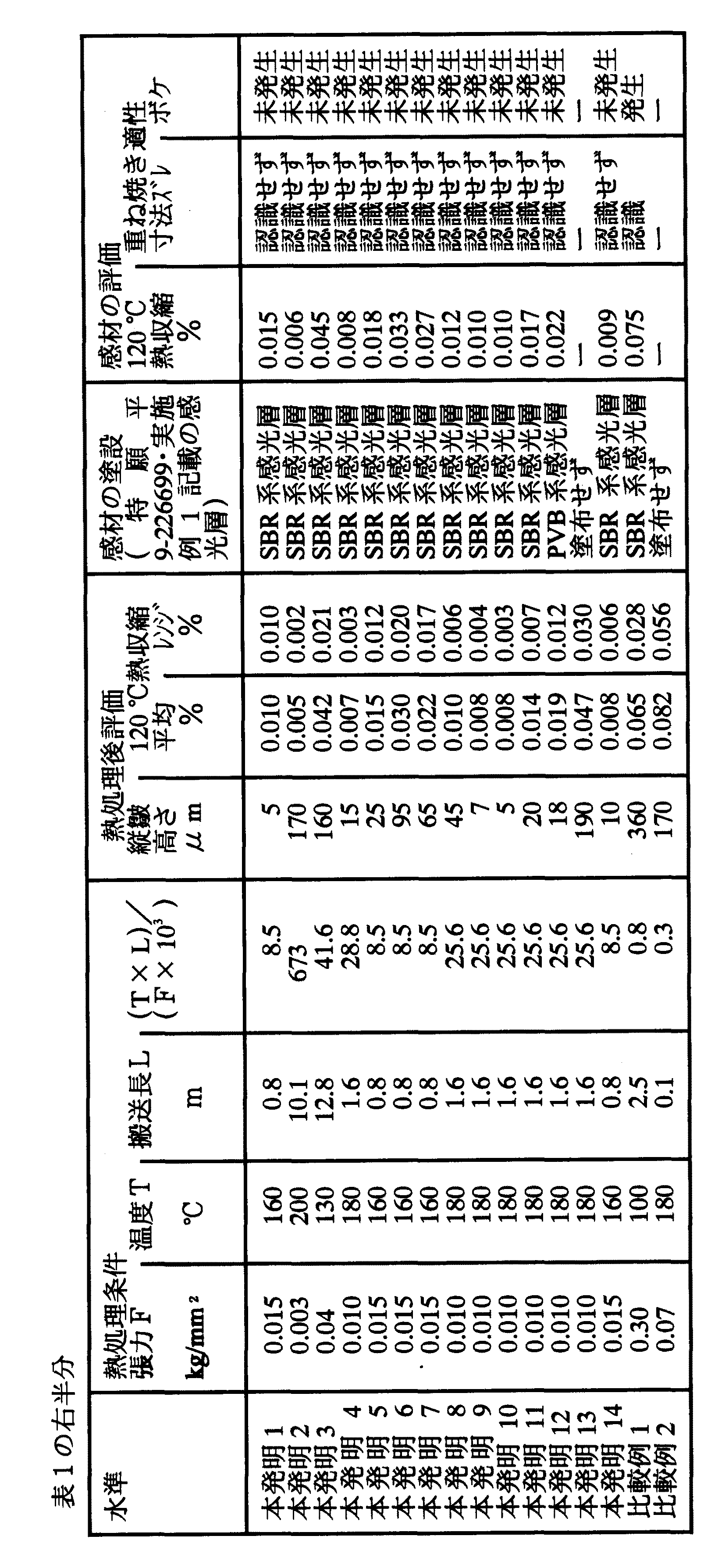
【表2】
(2−1)コロナ処理
塗布に先立ち両面にコロナ処理(ピラー社製ソリッドステートコロナ処理機6KVAモデルを用い、支持体の両面を室温下において20m/分で処理)を実施した。この時の電流、電圧の読み取り値から、支持体には0.375kV・A・分/m2の処理がなされている。この時の処理周波数は9.6kHz、電極と誘電体ロールのギャップクリアランスは1.6mmであった。この上に下記層を塗設した。
(2−2)下塗第1層
下記組成の水分散ラテックスをワイヤーバーを用いて乾燥膜厚が0.3μmとなるよう塗布し120℃で2分間乾燥した。
ブタジエン−スチレン共重合ラテックス 13ml
(固形分43%、ブタジエン/スチレン重量比=32/68)
2,4−ジクロロ−6−ヒドロキシ−S−トリアジンナトリウ 7ml
ム塩 8%水溶液
ラウリルベンゼンスルホン酸ナトリウム 1%水溶液 1.6ml
コロイダルシリカ 粒径と量は表1に記載
蒸留水 80ml
【0026】
(2−3)下塗第2層
下記組成の水溶液をワイヤーバーを用いて乾燥膜厚が0.14μmとなるように塗布した。塗布の有無および乾燥条件は表1に示した。
ゼラチン 0.9g
メチルセルロース(メトローズSM15 置換度1.79〜 0.1g1.83)
酢酸(濃度99%) 0.02ml
蒸留水 99ml
【0027】
(2−4)バック第1層(導電性層)
下記組成の導電性素材を含むアクリルラテックス水分散液を、乾燥膜厚が表1の値になるように塗布し180℃で30秒乾燥し、表面電気抵抗が106Ωの支持体を作成した。
アクリル樹脂水分散液 2.0重量部
(ジュリマ−ET410、固形分20重量%、日本純薬(株) 製)
酸化スズ−酸化アンチモン水分散物 18.1重量部
(平均粒径0.1μm、17重量%)
ポリオキシエチレンフェニルエーテル 0.1重量部
コロイダルシリカ サイズ・添加量は表1に記載
これに蒸留水を加えて100重量部となるように調製した。
【0028】
(2−5)ポリオレフィン層(すべり層)
下記組成のポリオレフィンラテックス水分散液を、乾燥膜厚が表1の値になるように塗布した。塗布の有無および乾燥条件は表1に記載した。
ポリオレフィン 3.0重量部
(ケミパールS−120、27重量%、三井石油化学(株) 製)
コロイダルシリカ 2.0重量部
(スノーテックスC、日産化学(株) 製)
エポキシ化合物 0.3重量部
(デナコールEX−614B、ナガセ化成(株) 製)
蒸留水を加えて合計が100重量部になるように調製
(3)熱処理
熱処理に先だって上記の方法に従って下記の評価を実施し、結果を表1に示した。
▲1▼150℃熱収縮
▲2▼Ra、Rt
表1に示した条件で熱処理を実施した。
【0029】
(4)評価
熱処理後の熱可塑性フィルムに対し上記の方法に従って下記の評価を実施し、結果を表1に示した。
▲1▼縦皺
▲2▼120℃熱収縮
(5)感材の作成
上記下塗、バック層を塗設し熱処理を施した熱可塑性フィルムの下塗側に表1に示した感光層を塗設した。これを発光時間10−4SECのキセノンフラッシュ光でテストパターンを焼き付けた後特表平7−505488号に記載の熱現像機を用いて120℃で30秒現像を行った。これをPS版に焼き付けたところ、本発明では良好な平面性と寸法安定性を達成し良好な焼き付けを実現した。一方比較例では焼き付け時に縦皺に起因するボケと寸法変化に起因する焼き付けズレを発生した。
【0030】
【発明の効果】
本発明の熱可塑性フィルムは平面性が良好であり熱寸法安定性にすぐれ写真用支持体として用いた時に熱現像による寸法変化によるボケや焼き付けズレなどの故障を惹起しない。[0001]
BACKGROUND OF THE INVENTION
The present invention relates to an aromatic polyester film support and a photographic light-sensitive material using the same.
[0002]
[Prior art]
Conventional photographic light-sensitive materials are subjected to wet development using a developer after photographing. However, this method has the following problems, and improvement of this point has been desired.
(1) Since development, bleaching, fixing, and drying are performed, time is required for development processing.
(2) Since a plurality of tanks containing developer are required, the developing machine cannot be reduced in size and weight.
(3) Replenishment of developer, disposal, and cleaning of the developing tank are required.
In order to improve this, 80-150 ° C. as described in US Pat. No. 3,152,904, US Pat. No. 3,457,075, Japanese Examined Patent Publication No. 43-4921, Japanese Examined Patent Publication No. 43-4924, etc. A photographic material is proposed which is processed by a heat developing method (hereinafter sometimes abbreviated as heat development). As an example of this, there is a method in which a precursor of a developer is previously contained in the photosensitive layer, which is decomposed by heat to form a developer, and then developed. In such a thermal development system, the development process can be performed in a short time only by applying heat, and the developing machine can be downsized. Furthermore, there is no need to worry about replenishment or disposal of the developer.
However, when this type of photosensitive material is used as a printing photosensitive material, color shift occurs when four plates (blue, green, red, black) are stacked due to dimensional changes that occur during thermal development. There is a difficulty. In order to solve this, conventional methods for heat-treating a photographic support under low tension are known (for example, JP-A-60-22616, JP-A-64-64883, JP-A-54). -158470, U.S. Pat. No. 2,796,684). By applying these low-tensile heat treatments, the dimensional change before and after heat development could be reduced, but with this, poor flatness (vertical failure: vertical piles in the longitudinal direction of the support, The wrinkles generated at a pitch of 10 to 20 cm in the width direction are generated, which is a serious problem for a photographic support that requires high flatness. As a countermeasure against this, there is known a method of extending a ridge on a roll by passing between a large number of rolls as described in US Pat. No. 3,663,683. However, in this method, the tension loss generated in the pass roll is large, and it is difficult to convey with low tension, so that sufficient dimensional stability cannot be achieved.
[0003]
[Problems to be solved by the invention]
An object of the present invention is to provide a silver halide photographic support comprising an aromatic polyester film having good flatness and excellent thermal dimensional stability, and a silver halide photographic light-sensitive material using the same.
[0004]
[Means for Solving the Problems]
These problems have been achieved by the following means.
That is, the present invention
(1)An aromatic polyester film having a thermal shrinkage at 150 ° C. of 0.01% or more and 0.4% or less is heat-treated while being transported under the conditions simultaneously satisfying the following formulas (1) to (3);Silver halide photographic light-sensitive material comprising an aromatic polyester film characterized by having a vertical gutter height of 0 μm to 200 μm and a longitudinal heat shrinkage at 120 ° C. of 0.001% to 0.05%. Support.
0.001 ≦ F ≦ 0.05 (1)
120 ≦ T ≦ 220 (2)
1 ≦ (T × L) / (F × 1000) ≦ 800 (3)
F = Conveyance tension per unit cross-sectional area applied to the thermoplastic film
Force (kg / mm 2 )
T = heat treatment temperature (° C)
L = longest non-contact transport length in heat treatment zone (m)
(2) An aromatic polyester film having a ten-point average roughness (Rz) of 0.18 μm to 8.0 μm and a maximum point height (Rt) of 0.3 μm to 10 μm.SaidA support for a silver halide photographic light-sensitive material comprising the aromatic polyester film according to (1) obtained by heat treatment.
(3)An aromatic polyester film having an undercoat layer containing a matting agent and a backing layer,Silver halide photographic light-sensitive material comprising an aromatic polyester film characterized by having a vertical gutter height of 0 μm to 200 μm and a longitudinal heat shrinkage at 120 ° C. of 0.001% to 0.05%. Support.
(4) The support for a silver halide photographic light-sensitive material comprising the aromatic polyester film according to (3), wherein the matting agent has a particle size of 0.1 to 15 μm.
(5) Any one of (1) to (4)A silver halide photographic light-sensitive material, which is used as a support for the aromatic polyester film described in 1.
(6) It is a heat-developable photographic photosensitive material (5)The silver halide photographic light-sensitive material described.
[0005]
The present invention has been made clear that the downside failure occurs as a result of the thermoplastic film shrinking between rolls during the heat treatment process. That is, when heat treatment is performed at a high temperature with low tension, the support tends to shrink. However, shrinkage is suppressed on the pass roll by the frictional force between the film and the roll. On the other hand, since it can shrink freely between rolls, the width of the film is reduced. In order to eliminate such a difference in width between the roll and the roll, undulation occurs in the vicinity of the roll. Creeping is easy at high temperatures, and such deformation becomes permanent. Therefore, such vertical warp tends to occur when transporting at high temperature and low tension.
Therefore, warp is more likely to occur as the length between the pass rolls in the heat treatment zone, that is, the non-contact conveyance length is longer, and is likely to occur as the temperature is higher and the tension is smaller. In the method of the present invention, this heat treatment is performed without the occurrence of vertical lines.
[0006]
DETAILED DESCRIPTION OF THE INVENTION
The manufacturing method of the aromatic polyester film used as a thermoplastic film in the present invention is as follows.
(A) It can be manufactured by heat-treating while being transported under the conditions satisfying the following formulas (1) to (3).
0.001 ≦ F ≦ 0.05 (1)
120 ≦ T ≦ 220 (2)
1 ≦ (T × L) / (F × 1000) ≦ 800 (3)
F = Conveying tension per unit cross-sectional area applied to the thermoplastic film (kg / mm 2)
T = heat treatment temperature (° C)
L = longest non-contact transport length in heat treatment zone (m)
(B) 150 ° C. heat shrinkage before heat treatment of the thermoplastic film is 0.01% or more and 0.4% or less, and the heat treatment described in (a) is performed and manufactured.
(C) The difference between the maximum value and the minimum value of the width direction distribution of heat shrinkage at 150 ° C. before heat treatment of the thermoplastic film is 0% or more and 0.1% or less. The described thermoplastic film is produced.
(D) The ten-point average roughness (Rz) of the thermoplastic film before heat treatment is 0.18 μm or more and 8.0 μm or less, and the maximum point height (Rt) is 0.3 μm or more and 10 μm or less. ) ~ (B)The heat treatment method described is performed and manufactured. If the conveying tension F exceeds the range of the present invention, thermal shrinkage tends to increase, which is not preferable. On the other hand, if it is less than the range of the present invention, it is not preferable because a trouble such as meandering is likely to occur. Transport tension is usually 0.001kg / mm20.05 kg / mm2Or less, preferably 0.003 kg / mm20.03 kg / mm2Or less, more preferably 0.007 kg / mm20.02 kg / mm or more2It is as follows. Such tension can be achieved by adjusting a motor installed on at least one of the winding side and the feeding side. At this time, it is preferable to adjust the tension pickup while monitoring the tension. However, since it is easy to collapse when it is wound with such a low tension, it is preferable to wind with a high tension after the tension cut in front of the winding portion.
[0007]
The heat treatment temperature is usually 120 ° C. or higher and 220 ° C. or lower, preferably 135 ° C. or higher and 200 ° C. or lower, and more preferably 145 ° C. or higher and 180 ° C. or lower. If this temperature range is exceeded, oligomers contained in the thermoplastic film are deposited on the surface and haze is likely to increase, which is not desirable. Below this temperature range, thermal shrinkage tends to increase and the object of the invention cannot be achieved. Such temperature control may be achieved by blowing hot air into a heat treatment zone using a heat insulating material, or the plastic film may be heated by heat transfer in contact with a high-temperature heat medium such as a heat roll. The temperature may be raised by radiant heat using an infrared heater or the like. Any method may be used, but it is preferable to reduce the temperature distribution in the width direction in order to reduce the width direction distribution of heat shrinkage. This can be achieved by installing fins at the hot air outlet and adjusting the direction of the air to eliminate the accumulation of the air, or by dividing and controlling the heat roll and infrared heater so that the temperature at both ends tends to be high. Can be achieved. Here, the heat treatment temperature T is higher than the glass transition temperature Tg.
[0008]
The maximum length between pass rolls is usually in the range of 1 ≦ (T × L) / (F × 1000) ≦ 800 shown in the above equation (3) as a function of tension (F) and heat treatment temperature (T), Preferably, it is set to satisfy 2 ≦ (T × L) / (F × 1000) ≦ 200, more preferably 4 ≦ (T × L) / (F × 1000) ≦ 80. Below this range, it is necessary to install a large number of pass rolls with a short roll interval, and it is necessary to set a large conveying tension due to the tension loss occurring here, and the dimensional stability tends to deteriorate. On the other hand, if it exceeds this range, shrinkage of the base width tends to be large, and vertical wrinkles tend to occur, which is not desirable. The length between pass rolls here refers to the maximum length existing in the heat treatment zone. This is because if a single point exceeds the range of the present invention, vertical lines occur there, so the maximum length needs to be within the above range. This is important because downspout once generated between pass rolls is hard to disappear.
[0009]
Furthermore, the present invention can further reduce the problem of downpipe by improving the thermoplastic film used. The 1st makes 150 degreeC heat shrink of the thermoplastic film before heat processing 0.01% or more and 0.4% or less.. GoodPreferably, 0.05% or more and 0.3% or less, more preferably 0.1% or more and 0.25% or less is used. That is, by using a thermoplastic film having a small heat shrinkage, there is an effect of reducing the shrinkage between the pass rolls generated during the heat treatment and suppressing the occurrence of warp. If the heat shrinkage exceeds 0.4%, the dimensional stability of the photographic image is deteriorated. On the other hand, a thermoplastic film having a 150 ° C. heat shrinkage lower than the above range has sufficiently high thermal dimensional stability, and there is no need to carry out the heat treatment of the present invention. Such a support isa.Improved stretching conditions,b.There is a method of pre-heat treatmentbThe method is more preferable.bIn this method, the heat treatment is performed at 120 to 220 ° C., more preferably 130 to 200 ° C., further preferably 150 to 190 ° C. before the heat treatment of the present invention. Thus, heat shrinkage is performed to some extent in advance to reduce the amount of heat shrinkage generated by the heat treatment of the present invention. Therefore, since this pre-heat treatment does not require high dimensional stability like the above heat treatment, it is preferable to prevent the occurrence of warp by increasing the tension accordingly. Such a heat treatment may be performed alone, but when there is a coating process, it is efficient to perform it in the subsequent drying process. When used as a photographic support, it is preferably carried out in this drying step in order to coat a primer and a backing layer.
on the other handMethod aCan be achieved by decreasing the draw ratio and increasing the heat setting temperature, both of which are in the direction of decreasing the elastic modulus of the thermoplastic film, and are not so preferred.
[0010]
Next, the second improvement of the thermoplastic film is that the difference between the maximum value and the minimum value of the 150 ° C. heat shrinkage width direction distribution before heat treatment is 0% or more and 0.10 or less, more preferably 0% or more and 0.07%. Hereinafter, it is more preferable to use a thermoplastic film of 0% or more and 0.05% or less. That is, it is preferable to use a thermoplastic film having uniform heat shrinkage in the width direction. This is because if there is unevenness in the amount of heat shrinkage, it will shrink greatly locally and tend to cause downfall. Such a thermoplastic film can be achieved by (1) improvement of film forming conditions and (2) pre-heat treatment. {Circle around (1)} can be achieved by raising the heat setting temperature for the end portion where heat shrinkage tends to increase. {Circle around (2)} is the same as described above, and attempts to reduce the difference between the maximum value and the minimum value by reducing the absolute value of heat shrinkage.
[0011]
Third, the ten-point average roughness (Rz) of the thermoplastic film is preferably 0.18 μm or more and 8.0 μm or less, more preferably 0.20 μm or more and 6.0 μm or less, and even more preferably 0.3 μm or more. It is 4.5 μm or less. Rz refers to the difference between the average value of 10 points from the highest of the peaks present in the reference length and the average value of 10 points from the deepest valley. That is, when the height of the protrusion larger than the average unevenness (average roughness; Ra) is within the range of the present invention, the friction between the roll and the thermoplastic film can be effectively lowered. For the same reason, the maximum point height (Rt) Between 0.3 μm and 10.0 μm, more preferably between 0.4 μm and 8.0 μm, and even more preferably between 0.6 μm and 6.0 μm. Rt indicates the difference between the highest protrusion and the deepest valley present in the reference length. If both Rz and Rt are less than the range of the present invention, the flatness tends to be lowered, and if it exceeds, the added fine particles are peeled off to cause roll contamination, which is not preferable.
[0012]
Such a thermoplastic film adjusts the friction with the pass roll by imparting irregularities to the surface of the thermoplastic film, and makes it easy to heat shrink even on the pass roll. Since it can shrink | contract similarly to the thermoplastic film between the pass rolls which are not receiving the restraining force by this, generation | occurrence | production of a vertical wrinkle can be reduced. Exceeding the scope of the present invention is not preferable because the fine particles added to achieve the surface roughness peel off and contaminate the process. On the other hand, if it falls below, the effect cannot be obtained and the vertical warp tends to occur. Such a thermoplastic film can be supported by (1) providing a fine particle layer on the outermost surface, and (2) increasing the amount of fine particles (filler) added to the thermoplastic film.
[0013]
The method of (1) is an inorganic material such as silica, alumina, barium sulfate, calcium carbonate, titania, tin oxide, indium oxide, talc, or organic materials such as polystyrene, polymethyl methacrylate, polymethacrylate, polyacrylonitrile, cellulose, gelatin and the like. A method of coating fine particles together with a binder is mentioned. The shape of these fine particles is not particularly limited, and can be used in a needle shape, a spherical shape, a plate shape, or a crushed shape. A preferable size is 0.1 to 15 μm, more preferably 0.2 to 10 μm, and still more preferably 0.3 to 7 μm. The amount of matting agent added is 1m on one side2It is 0.1 to 50 mg per unit, more preferably 0.2 to 30 mg, and still more preferably 0.3 to 20 mg. Among these fine particles, ZnO and TiO are particularly preferable.2, SnO2, Al2O3, In2O3, SiO2, MgO, BaO, MoO3, V2O5At least one crystalline metal oxide selected from the group consisting of fine particles of these composite oxides. Further preferred is SnO2Is a conductive material containing about 5 to 20% of antimony oxide and / or further containing other components (for example, silicon oxide, boron, phosphorus, etc.). When these conductive fine particles are used, it is possible to suppress a dusty failure due to static electricity generated during the heat treatment. These conductive inorganic fine particles have a volume resistivity of 107Ωcm or less, more preferably 106Ωcm or less, more preferably 105Ωcm or less. The binder for dispersing these fine particles is not particularly limited, and gelatin, water-soluble polyester, polyurethane, styrene-butadiene rubber, polyvinylidene chloride, polyvinyl chloride, polyurethane, polyacrylic ester, polymethacrylic ester, polyamide, etc. should be used. Can do.
[0014]
Prior to these coatings, it is also preferable to carry out glow discharge treatment, corona treatment, ultraviolet treatment, and flame treatment to improve adhesion. Moreover, these coating methods can use a well-known method. For example, a dip coating method, an air knife coating method, a curtain coating method, a roller coating method, a wire bar coating method, a gravure coating method, an extrusion coating method using a hopper described in US Pat. No. 2,681,294, or US Pat. No. 2,761,418 Multi-layer simultaneous coating methods described in US Pat. Nos. 3,508,947 and 2,761791 can be used.
[0015]
The method (2) is a method in which a filler such as an inorganic substance such as silica, alumina, barium sulfate, calcium carbonate, titania, tin oxide, indium oxide and talc is kneaded into the thermoplastic film. There is no restriction | limiting in particular in the shape of these fillers, A needle shape, a spherical shape, a plate shape, and a crushed shape can be used. A preferable size is 0.01 to 10 μm, more preferably 0.05 to 5 μm, and still more preferably 0.1 to 3 μm. The amount of filler added is 10 to 1000 ppm, more preferably 20 to 500 ppm, and still more preferably 30 to 300 ppm.
[0016]
The thermoplastic film that can be produced by applying the heat treatment method of the present invention is made of an aromatic polyester. The aromatic polyester as used herein refers to a compound in which 50 mol% or more of the dicarboxylic acid forming the polyester is composed of an aromatic dicarboxylic acid. More specifically, a polyethylene terephthalate polymer (PET), a polyethylene naphthalate polymer, a polybutylene terephthalate polymer, and a polybutylene naphthalate polymer can be mentioned. More preferred are polyethylene terephthalate and polyethylene naphthalate. Their average molecular weight (Mw ) Is preferably from 5,000 to 1,000,000, more preferably from 10,000 to 300,000.
[0017]
This thermoplastic film is preferably formed into two or more axes. For example, the melting point (Tm) ~ TmAfter melting between + 50 ° C, the glass transition temperature (Tg-50 ° C ~ TgExtruded into a + 20 ° C. cooling drum to form an unstretched sheet. At this time, electrostatic application to the cooling drum is also preferable. This unstretched sheet is Tg~ TgStretched vertically between 2 and 4 times between + 60 ° C and Tg~ TgStretch laterally between 2 and 5 times between + 60 ° C. Tm-60 ° C to TmAnd heat-fix for 5 seconds to 1 minute. After this Tm-60 ° C to TmIt is also preferable to relax by 0 to 10% in at least one of horizontal / vertical. It is also preferable that the film is stretched again in the vertical / horizontal direction. The thickness of the thermoplastic film thus obtained is preferably 50 to 500 μm, more preferably 70 to 300 μm, still more preferably 90 to 200 μm.
[0018]
By carrying out the present invention described above, the height of the vertical hook is 0 μm or more and 200 μm or less, more preferably 0 μm or more and 150 μm or less, and further preferably 0 μm or more and 100 μm or less, and the longitudinal direction at 120 ° C. Excellent thermal dimensional stability with high thermal shrinkage of 0.001% to 0.05%, more preferably 0.001% to 0.04%, and even more preferably 0.001% to 0.03% Thermoplastic film can be made. As a result, when used as a photographic support, particularly when used as a photographic material support with thermal development, high-quality images that do not cause image displacement or blurring when overprinted on a printing original plate (PS plate) are used. A support can be provided.
The photographic light-sensitive material of the present invention can be formed by coating a photographic light-sensitive layer on the support thus obtained. As preferred photographic light-sensitive materials, those described in Japanese Patent Application No. 9-226699, Japanese Patent Application No. 8-158652, and the like can be used.
[0019]
The measurement method used in the present invention will be described below.
(1) Vertical support height After cutting, the support is cut into a width of 50 cm and a length of 30 cm. This is floated on water so that bubbles do not enter, and this is scanned with a laser focus displacement meter (for example, LC2210 manufactured by Keyence Corporation) in the width direction at 50 cm / min. The maximum value-minimum value (excluding both ends) obtained in this way was defined as the vertical height in the width direction of the support.
(2) The thermoplastic film before heat shrinkage heat treatment at 150 ° C. is cut into a longitudinal direction (longitudinal direction; MD) of 25 cm × width direction (TD) of 5 cm. Two holes are made at intervals of 20 cm in this, and the sample is measured with a pin gauge after humidity adjustment for 12 hours or more at 25 ° C. and 60% RH (this length is L1And). After that, it is left for 30 minutes without applying tension to an air constant temperature bath at 150 ° C. After that, after adjusting the humidity at 25 ° C. and 60% RH for 12 hours or more, measure the length again using a pin gauge (this length is L2And). The thermal dimensional change rate is obtained based on the following formula.
150° C heat shrink (%) = {100 × (L1-L2) / L1} Absolute value Measured at points obtained by dividing this measurement into 5 in the width direction, and an average value, maximum value, and minimum value are obtained.
[0020]
(3) 120 ° C heat shrinkage
The thermoplastic film after the heat treatment is cut into a longitudinal direction (MD) 25 cm × width direction (TD) 5 cm. Two holes are made at intervals of 20 cm in this, and the sample is measured with a pin gauge after humidity adjustment for 12 hours or more at 25 ° C. and 60% RH (this length is L1And). Thereafter, it is pressed against a smooth stainless steel plate having a thickness of 10 mm heated to 120 ° C. for 30 seconds. After that, after adjusting the humidity at 25 ° C. and 60% RH for 12 hours or more, measure the length again using a pin gauge (this length is L2And). The thermal dimensional change rate is obtained based on the following formula.
120 ° C. thermal shrinkage (%) = {100 × (L1-L2) / L1} Absolute value
This is measured at both ends and the center of the thermoplastic film to determine the average value.
(4) Ten-point average roughness (Rz), Maximum roughness (Rt)
Using a universal surface shape measuring instrument SE-3C manufactured by Kosaka Laboratory Ltd., measurement is performed under the following conditions at 25 ° C. and 60% RH.
Measurement length: 2.5mm
Cut-off: 0.25mm
The measurement is performed on both sides of the sample film, and the surface with the larger value is displayed.
(5) Tension
A differential transformer type tension tester (for example, LX-TC-100 manufactured by Mitsubishi Electric Corporation) was installed on the roll immediately before and after the heat treatment zone, and the tension at 25 ° C. was measured to obtain an average value thereof.
[0021]
【Example】
Examples are shown below, but the present invention is not limited thereto.
Example-1
(1) Production of support
(1-1) Preparation of polyethylene terephthalate (PET) support
Using terephthalic acid and ethylene glycol, PET of IV = 0.66 (measured in phenol / tetrachloroethane = 6/4 (weight ratio) at 25 ° C.) was obtained according to a conventional method. This was pelletized, dried at 130 ° C. for 4 hours, melted at 300 ° C., extruded from a T-die, and then rapidly cooled to prepare an unstretched film having a thickness such that the film thickness after heat setting was 120 μm. .
This was longitudinally stretched 3.3 times using rolls with different peripheral speeds, and then stretched 4.5 times with a tenter. The temperatures at this time were 110 ° C. and 130 ° C., respectively. Thereafter, the film was heat-fixed at 240 ° C. for 20 seconds and relaxed by 4% in the lateral direction at the same temperature. Thereafter, the chuck portion of the tenter was slit, and knurling was applied to both ends with a width of 1 cm.
[0022]
(1-2) Preparation of polyethylene-2,6-naphthalate (PEN) support
Using dimethyl naphthalene-2,6-dicarboxylate and ethylene glycol, PEN of IV = 0.58 (measured in phenol / tetrachloroethane = 6/4 (weight ratio) at 25 ° C.) was obtained according to a conventional method. This was pelletized, dried at 150 ° C. for 4 hours, melted at 320 ° C., extruded from a T-die, and then rapidly cooled to prepare an unstretched film having a thickness such that the film thickness after heat setting was 120 μm. .
This was longitudinally stretched 2.8 times using rolls having different peripheral speeds, and then laterally stretched 3.7 times with a tenter. The temperatures at this time were 140 ° C. and 150 ° C., respectively. Thereafter, the film was heat-fixed at 250 ° C. for 20 seconds and relaxed by 4% in the lateral direction at the same temperature. Thereafter, the chuck portion of the tenter was slit, and knurling was applied to both ends with a width of 1 cm.
(2) Creation of coating layer
The following undercoat and back coat layers were provided on the support as shown in Table 1.
[0023]
[Table 1]
[Table 2]
(2-1) Corona treatment
Prior to coating, corona treatment was performed on both sides (using a solid-state corona treatment machine 6KVA model manufactured by Pillar, treating both sides of the support at 20 m / min at room temperature). From the current and voltage readings at this time, the support is 0.375 kV · A · min / m.2Is being processed. The treatment frequency at this time was 9.6 kHz, and the gap clearance between the electrode and the dielectric roll was 1.6 mm. The following layers were coated on this.
(2-2) Undercoat first layer
A water-dispersed latex having the following composition was applied using a wire bar to a dry film thickness of 0.3 μm and dried at 120 ° C. for 2 minutes.
Butadiene-styrene copolymer latex 13ml
(Solid content 43%, butadiene / styrene weight ratio = 32/68)
2,4-dichloro-6-hydroxy-S-triazine sodium 7 ml
Mu salt 8% aqueous solution
1.6% sodium laurylbenzenesulfonate 1% aqueous solution
Colloidal silica Particle size and amount are listed in Table 1.
80ml of distilled water
[0026]
(2-3) Undercoat second layer
An aqueous solution having the following composition was applied using a wire bar so that the dry film thickness was 0.14 μm. The presence / absence of coating and drying conditions are shown in Table 1.
Gelatin 0.9g
Methyl cellulose (Metroise SM15, substitution degree: 1.79 to 0.1 g 1.83)
Acetic acid (concentration 99%) 0.02ml
99ml of distilled water
[0027]
(2-4) Back first layer (conductive layer)
An acrylic latex aqueous dispersion containing a conductive material having the following composition was applied so that the dry film thickness was the value shown in Table 1, dried at 180 ° C. for 30 seconds, and the surface electrical resistance was 106An Ω support was prepared.
Acrylic resin aqueous dispersion 2.0 parts by weight
(Jurima-ET410, solid content 20% by weight, manufactured by Nippon Pure Chemicals Co., Ltd.)
Tin oxide-antimony oxide aqueous dispersion 18.1 parts by weight
(Average particle size 0.1 μm, 17% by weight)
0.1 parts by weight of polyoxyethylene phenyl ether
Colloidal silica Size and amount added are listed in Table 1.
Distilled water was added thereto to prepare 100 parts by weight.
[0028]
(2-5) Polyolefin layer (slip layer)
A polyolefin latex aqueous dispersion having the following composition was applied so that the dry film thickness was as shown in Table 1. The presence / absence of application and drying conditions are shown in Table 1.
3.0 parts by weight of polyolefin
(Kemipearl S-120, 27% by weight, manufactured by Mitsui Petrochemical Co., Ltd.)
Colloidal silica 2.0 parts by weight
(Snowtex C, manufactured by Nissan Chemical Co., Ltd.)
Epoxy compound 0.3 parts by weight
(Denacol EX-614B, manufactured by Nagase Kasei Co., Ltd.)
Prepared to add 100 parts by weight with distilled water
(3) Heat treatment
Prior to the heat treatment, the following evaluation was performed according to the above method, and the results are shown in Table 1.
(1) 150 ° C heat shrinkage
▲ 2 ▼ Ra, Rt
Heat treatment was performed under the conditions shown in Table 1.
[0029]
(4) Evaluation
The following evaluation was performed on the thermoplastic film after the heat treatment according to the above method, and the results are shown in Table 1.
▲ 1 ▼ downspout
(2) 120 ° C heat shrinkage
(5) Creation of photosensitive material
The photosensitive layer shown in Table 1 was applied to the undercoat side of the thermoplastic film on which the above-mentioned undercoat and back layers had been applied and heat-treated. This is the light emission time 10-4After printing the test pattern with SEC xenon flash light, development was performed at 120 ° C. for 30 seconds using a heat developing machine described in JP 7-505488. When this was baked on a PS plate, in the present invention, good flatness and dimensional stability were achieved, and good baking was realized. On the other hand, in the comparative example, blurring caused by vertical flaws and burning deviation caused by dimensional change occurred during baking.
[0030]
【The invention's effect】
The thermoplastic film of the present invention has good flatness and excellent thermal dimensional stability, and when used as a photographic support, it does not cause failures such as blurring and printing misalignment due to dimensional changes due to thermal development.
Claims (6)
0.001≦F≦0.05 (1)
120≦T≦220 (2)
1≦(T×L)/(F×1000)≦800 (3)
F=熱可塑性フィルムに加わる単位断面積当りの搬送張
力(kg/mm 2 )
T=熱処理温度(℃)
L=熱処理ゾーン中の最長非接触搬送長(m) An aromatic polyester film having a thermal shrinkage at 150 ° C. of 0.01% or more and 0.4% or less is heat-treated while being transported under the conditions satisfying the following formulas (1) to (3) at the same time, and has a vertical height. A support for a silver halide photographic light-sensitive material comprising an aromatic polyester film, wherein the heat shrinkage in the longitudinal direction at 120 ° C. is from 0.001% to 0.05%.
0.001 ≦ F ≦ 0.05 (1)
120 ≦ T ≦ 220 (2)
1 ≦ (T × L) / (F × 1000) ≦ 800 (3)
F = Conveyance tension per unit cross-sectional area applied to the thermoplastic film
Force (kg / mm 2 )
T = heat treatment temperature (° C)
L = longest non-contact transport length in heat treatment zone (m)
Priority Applications (1)
| Application Number | Priority Date | Filing Date | Title |
|---|---|---|---|
| JP2002167783A JP3662230B2 (en) | 2002-06-07 | 2002-06-07 | Support composed of aromatic polyester film and photographic light-sensitive material using the same |
Applications Claiming Priority (1)
| Application Number | Priority Date | Filing Date | Title |
|---|---|---|---|
| JP2002167783A JP3662230B2 (en) | 2002-06-07 | 2002-06-07 | Support composed of aromatic polyester film and photographic light-sensitive material using the same |
Related Parent Applications (1)
| Application Number | Title | Priority Date | Filing Date |
|---|---|---|---|
| JP30889897A Division JP3340063B2 (en) | 1997-11-11 | 1997-11-11 | Method for producing aromatic polyester film |
Publications (2)
| Publication Number | Publication Date |
|---|---|
| JP2003098632A JP2003098632A (en) | 2003-04-04 |
| JP3662230B2 true JP3662230B2 (en) | 2005-06-22 |
Family
ID=19195069
Family Applications (1)
| Application Number | Title | Priority Date | Filing Date |
|---|---|---|---|
| JP2002167783A Expired - Fee Related JP3662230B2 (en) | 2002-06-07 | 2002-06-07 | Support composed of aromatic polyester film and photographic light-sensitive material using the same |
Country Status (1)
| Country | Link |
|---|---|
| JP (1) | JP3662230B2 (en) |
-
2002
- 2002-06-07 JP JP2002167783A patent/JP3662230B2/en not_active Expired - Fee Related
Also Published As
| Publication number | Publication date |
|---|---|
| JP2003098632A (en) | 2003-04-04 |
Similar Documents
| Publication | Publication Date | Title |
|---|---|---|
| JP7543808B2 (en) | Polyester Film | |
| JP2009233919A (en) | Antistatic laminated polyester film for mold release | |
| JPH0772585A (en) | Polyester substrate | |
| JP7463665B2 (en) | Polyester Film Roll | |
| JP7463905B2 (en) | Biaxially oriented polyester film for dry film resist | |
| JP7169551B2 (en) | Biaxially oriented polyester film roll for release | |
| JP2018065250A (en) | Biaxially oriented polyester film for dry film resist support and method for producing the same | |
| US20010038907A1 (en) | Laminated polyester film | |
| JP3290118B2 (en) | Polyester support | |
| JP3662230B2 (en) | Support composed of aromatic polyester film and photographic light-sensitive material using the same | |
| JP7206857B2 (en) | polyester film | |
| JP3340063B2 (en) | Method for producing aromatic polyester film | |
| JP3948500B2 (en) | Method for heat treatment of photographic film | |
| JP2023046291A (en) | Biaxially oriented polyester film and its manufacturing method | |
| JP2023114422A (en) | Polyester film, method for producing polyester film, and method for producing multilayer ceramic capacitor | |
| JP3676156B2 (en) | Heat treatment method for biaxially stretched polyester film | |
| JPH11221892A (en) | Low heat shrinkage polyester film and low heat shrinkage thermal developing photosensitive material | |
| JP2000030972A (en) | Carrier sheet for ceramic capacitor production | |
| JP2004255705A (en) | Release film | |
| JP2025090022A (en) | Polyester film roll and method for producing polyester film roll | |
| JP2002018947A (en) | Biaxially oriented polyester film and method for producing the same | |
| JP2002018946A (en) | Easy adhesion biaxially oriented polyester film and method for producing the same | |
| JP2025137346A (en) | Biaxially oriented polyester film for dry film resist | |
| JPH11170358A (en) | Biaxially oriented polyester film and method for producing the same | |
| JP2025099692A (en) | Polyester Film |
Legal Events
| Date | Code | Title | Description |
|---|---|---|---|
| A131 | Notification of reasons for refusal |
Effective date: 20040706 Free format text: JAPANESE INTERMEDIATE CODE: A131 |
|
| A131 | Notification of reasons for refusal |
Free format text: JAPANESE INTERMEDIATE CODE: A131 Effective date: 20041102 |
|
| A521 | Written amendment |
Free format text: JAPANESE INTERMEDIATE CODE: A523 Effective date: 20041228 |
|
| TRDD | Decision of grant or rejection written | ||
| A01 | Written decision to grant a patent or to grant a registration (utility model) |
Effective date: 20050308 Free format text: JAPANESE INTERMEDIATE CODE: A01 |
|
| A61 | First payment of annual fees (during grant procedure) |
Free format text: JAPANESE INTERMEDIATE CODE: A61 Effective date: 20050322 |
|
| R150 | Certificate of patent (=grant) or registration of utility model |
Free format text: JAPANESE INTERMEDIATE CODE: R150 |
|
| S111 | Request for change of ownership or part of ownership |
Free format text: JAPANESE INTERMEDIATE CODE: R313111 |
|
| FPAY | Renewal fee payment (prs date is renewal date of database) |
Year of fee payment: 3 Free format text: PAYMENT UNTIL: 20080401 |
|
| R350 | Written notification of registration of transfer |
Free format text: JAPANESE INTERMEDIATE CODE: R350 |
|
| FPAY | Renewal fee payment (prs date is renewal date of database) |
Year of fee payment: 4 Free format text: PAYMENT UNTIL: 20090401 |
|
| FPAY | Renewal fee payment (prs date is renewal date of database) |
Year of fee payment: 4 Free format text: PAYMENT UNTIL: 20090401 |
|
| FPAY | Renewal fee payment (prs date is renewal date of database) |
Year of fee payment: 5 Free format text: PAYMENT UNTIL: 20100401 |
|
| FPAY | Renewal fee payment (prs date is renewal date of database) |
Free format text: PAYMENT UNTIL: 20110401 Year of fee payment: 6 |
|
| LAPS | Cancellation because of no payment of annual fees |