JP3661487B2 - Endoscope observation device - Google Patents
Endoscope observation device Download PDFInfo
- Publication number
- JP3661487B2 JP3661487B2 JP13295799A JP13295799A JP3661487B2 JP 3661487 B2 JP3661487 B2 JP 3661487B2 JP 13295799 A JP13295799 A JP 13295799A JP 13295799 A JP13295799 A JP 13295799A JP 3661487 B2 JP3661487 B2 JP 3661487B2
- Authority
- JP
- Japan
- Prior art keywords
- observation
- illumination
- light
- illuminance
- distance
- Prior art date
- Legal status (The legal status is an assumption and is not a legal conclusion. Google has not performed a legal analysis and makes no representation as to the accuracy of the status listed.)
- Expired - Fee Related
Links
- 238000005286 illumination Methods 0.000 claims description 149
- 230000003287 optical effect Effects 0.000 claims description 29
- 238000003780 insertion Methods 0.000 claims description 28
- 230000037431 insertion Effects 0.000 claims description 28
- 238000003384 imaging method Methods 0.000 claims description 16
- 238000010586 diagram Methods 0.000 description 9
- 230000002093 peripheral effect Effects 0.000 description 9
- 230000008859 change Effects 0.000 description 6
- 230000000007 visual effect Effects 0.000 description 6
- 239000011521 glass Substances 0.000 description 5
- 230000007246 mechanism Effects 0.000 description 5
- 230000007423 decrease Effects 0.000 description 3
- 238000000034 method Methods 0.000 description 3
- 239000013307 optical fiber Substances 0.000 description 3
- 229920006395 saturated elastomer Polymers 0.000 description 3
- 230000015572 biosynthetic process Effects 0.000 description 2
- 238000004140 cleaning Methods 0.000 description 2
- 230000000694 effects Effects 0.000 description 2
- 239000012530 fluid Substances 0.000 description 2
- 230000008569 process Effects 0.000 description 2
- 210000002784 stomach Anatomy 0.000 description 2
- 239000000758 substrate Substances 0.000 description 2
- 230000009471 action Effects 0.000 description 1
- 238000005452 bending Methods 0.000 description 1
- 230000005540 biological transmission Effects 0.000 description 1
- 239000012141 concentrate Substances 0.000 description 1
- 238000003745 diagnosis Methods 0.000 description 1
- 238000007689 inspection Methods 0.000 description 1
- 238000009434 installation Methods 0.000 description 1
- 230000000873 masking effect Effects 0.000 description 1
- 230000009467 reduction Effects 0.000 description 1
- 230000000630 rising effect Effects 0.000 description 1
- 230000035945 sensitivity Effects 0.000 description 1
Images


Landscapes
- Endoscopes (AREA)
- Instruments For Viewing The Inside Of Hollow Bodies (AREA)
Description
【0001】
【発明の属する技術分野】
本発明は、医療用等として用いられる内視鏡において、観察距離が可変な対物レンズを有する観察手段を装着した内視鏡に関するものである。
【0002】
【従来の技術】
内視鏡は、患者の体内等に挿入されて、体腔内の観察等を行うために用いられるものであって、術者等が把持して操作を行う本体操作部と、体腔内等に挿入される挿入部とを有するものである。体腔内等は暗所であるから、その観察を行うためには外部から照明を行う必要がある。従って、挿入部の先端には概略同一平面の部位に照明手段と観察手段とが設けられる。照明手段は極細い光学繊維を束ねたライトガイドを照明光の伝送手段として用い、このライトガイドの出射端に照明光を発散させる照明用レンズを設ける構成となし、観察手段は対物レンズを有し、この対物レンズにより体腔内の像を結像させる。この対物レンズの結像位置には光学繊維束からなるイメージガイドを臨ませるようにしたものと、CCD等からなる固体撮像素子を結像位置に配置して、観察対象部の光学像を電気信号に変換するようにしたものとがある。前者は光学式内視鏡であり、体腔内の観察は本体操作部に連結して設けた接眼部に接眼することにより行われる。また、後者は、所謂電子内視鏡と呼ばれるものであり、固体撮像手段からの電気信号をプロセッサに伝送し、このプロセッサで処理して映像信号を生成するようになし、プロセッサに付設したモニタにこの映像が表示される。
【0003】
内視鏡を用いて体腔内、例えば胃内観察を行う際において、例えば胃内壁から観察手段を離した位置で観察を行う場合に加えて、体腔壁をより正確に検査するために、この体腔壁に対して至近位置から観察する場合もある。このように、至近位置からの観察時に対物レンズのピントが正確に合うように調整する、焦点調整機構を備える構成としたものは、例えば特公昭61−53698号公報等に示されている。そして、焦点調整機構としては、体腔内壁から1cm以下、特に1mm〜2mmというように、極めて近い位置にピントが合うように調整できる構成としたものがある。このように至近距離での観察を可能にすることによって、体腔内壁をより高精度に検査することができる。
【0004】
ところで、観察手段を構成する対物レンズの焦点が観察対象部に正確に合うように調整されたとしても、必ずしも正確な観察を行える訳ではない。既に説明したように、体腔内は暗所である関係から、ライトガイドと照明用レンズとからなる照明手段で照明するが、照明光は観察対象部全体をできるだけ均一な照度となるようにしなければならない。観察手段による観察領域の一部に暗い部分が生じると観察が困難になる。また、観察領域の一部分がそれ以外の部分と比較して極めて明るいと、観察領域全体における明暗の差が大きくなり、やはり観察に支障を来すことになる。とりわけ、固体撮像素子を用いた電子内視鏡の場合には、明る過ぎる部分があると、固体撮像素子における一部の画素が飽和状態になり、ブルーミングやスミアが発生することになり、また照明光の照度にむらがあると、画素の飽和はないまでも、ダイナミックレンジが低下して、良好な画質の画像が得られなくなる。
【0005】
観察手段の観察領域に対する照明むらを抑制するための手法は、例えば特開平6−169879号公報に開示されている。この従来技術によれば、挿入部の先端に設けられた観察手段の装着部に対して、その両側に等しい距離だけ離間した位置に2箇所の照明手段を設置し、これら2箇所の照明手段からほぼ等しい光量の照明光を照射するように構成している。そして、この場合、観察対象部における観察領域にできるだけ照明光を集中させるために、2つの照明手段は、観察手段に有害光が入らない等という条件下で、できるだけ観察手段に近接した位置に配置されている。
【0006】
【発明が解決しようとする課題】
ところで、内視鏡の挿入部は体腔内に挿入される関係から、挿入操作性及び患者の苦痛軽減等の観点から、できるだけ細径化する必要がある。しかも、このように細径の挿入部に設けられるのは、1箇所の観察手段及び2箇所の照明手段だけではない。例えば、鉗子その他の処置具を挿通させるための処置具挿通チャンネルが設けられ、また観察手段に向けて洗浄用流体を噴出させる機構を設ける場合もある。従って、設置スペースの関係から、2箇所設けられる照明手段における開口径は極めて小さくなり、実質的に点光源に近いものとなってしまう。ただし、ライトガイドの出射端には照明レンズを臨ませて設け、この照明レンズで照明光を発散させるようにしている。その結果、観察対象部である体腔内壁が照明手段からある程度の距離だけ隔たっておれば、観察手段による観察領域はほぼ均一な照度で照明される。しかしながら、観察距離が近くなると照明レンズでは光を十分発散させることができなくなる。特に、観察手段が観察対象部から数mm、さらには1〜2mm程度しか離間しないというように、極めて近接した位置から観察対象部を照明する場合には、照明窓の中心位置の照度が極めて高く、周辺に向かうに応じて急激に照度が低下するという照度分布が生じる。
【0007】
以上のことから、たとえ従来技術のように、照明手段が観察手段を挟んだ両側に配置したとしても、2つの照明手段を観察手段に近接した位置に配置されている限り、観察距離がある程度大きい場合には観察領域に照明光を集中させる上で有利であるものの、観察距離が1cm以下、特に数mmというように、最近接観察距離で観察する時には、観察領域の中心位置と周辺部との間の照度の差が極めて大きくなる。この結果、特に固体撮像素子で撮影した時に、周辺部分の照度が高すぎてその位置の画素が飽和してブルーミング,スミア等が発生するおそれがあり、またダイナミックレンジが低下して、S/N比が低下することになり、モニタ画面に鮮明な画像を表示できず、検査や診断の精度が悪くなる等といった問題点がある。
【0008】
本発明は以上の点に鑑みてなされたものであって、その目的とするところは、極めて簡単な構成で、最近接観察距離で観察する際における観察領域の照度のばらつきを最小限に抑制することにある。
【0009】
【課題を解決するための手段】
前述した目的を達成するために、本発明は、挿入部の先端の概略同一平面に、少なくとも2箇所の照明手段と、これら両照明手段間の位置に1箇所の観察手段とを設け、前記各照明手段は、ライトガイドと、このライトガイドからの照明光を発散させる照明レンズとを備え、また前記観察手段には少なくとも観察距離が可変な対物レンズを備え、この観察手段からの画像をモニタ画面に表示するようにした内視鏡の観察装置において、前記照明手段は前記観察手段の両側位置で、この観察手段から所定の距離だけ離間した位置に配置され、かつ前記モニタ画面の表示範囲は、マスクにより限定されるようになっており、前記観察手段により最近接観察距離で観察する時に、前記観察領域の中心部における照度に対して前記マスクにより設定された表示端位置が2倍以下の照度になるように設定されることをその特徴とするものである。
【0010】
ここで、モニタ画面上での表示において、観察領域の中心部と表示端位置を含む周辺部との照度差は、できるだけ小さい方が望ましい。ただし、照明光の光量は照明レンズの光軸中心をピークとしたガウシアン分布を有するものである。従って、光量変化がほぼフラットになる部分を利用すると、観察対象部に照射される光量そのものが極めて小さくなり、得られる画像の全体が暗くなってしまう。従って、観察領域の中心部と周辺部との照度差の下限としては1.2倍である。ここで、観察領域の中心部の照明光の照度に対して2倍を越えない照度となる位置はモニタ画面の画像が表示される領域のうちの周辺領域である。つまり、観察領域の周辺部というのは、対物レンズの視野自体の周辺部ではなく、モニタ画面における観察対象部の表示領域の端部である。観察手段として固体撮像素子を備える構成とした場合において、固体撮像素子やモニタ画面にマスクが施されている場合には、このマスク境界部分における照度が中心部分の照度の2倍を越えないように設定する。最近接観察距離が長くなれば、前述した構成を採用しなくても、照明用レンズの作用による照度分布の均一化が図られる。従って、照明用レンズの光の発散効果が十分発揮できない1cm以下の距離、特に最近接観察位置が数mmの場合に、本発明のよう構成して、照度分布の均一化を図ることにより良好な画質の画像が得られる。
【0011】
観察領域の中心部と周辺部との照度差をできるだけ小さくしようとすると、最近接観察距離での観察時には通常の観察距離で観察する時より照明光の照度が低下する。一般に、光源装置には、絞り等からなる光源光量調整手段を設ける等によって、照度を変化させる手段を備えている。そこで、最近接観察距離位置での観察時には、この照度変化手段により照明を明るくするように制御するのが望ましい。また、2つの照明手段間に第3の照明手段を設けて、この第3の照明手段を照度変化手段として機能させることもできる。とりわけ、焦点位置の調整を行うために、対物レンズの駆動手段として正逆回転モータを用いる場合には、この正逆回転モータにより対物レンズが最近接観察距離位置に変位した時に作動するスイッチを設けて、このスイッチに連動して第3の照明手段の点滅制御を行う構成とすることもできる。さらにまた、最近接観察距離での観察時に、通常の観察距離で観察する時よりゲインコントローラのゲイン量を大きくするように制御できる。挿入部の先端には観察手段及び照明手段を囲繞するフードを嵌合させて設ける構成としたものがあるが、この場合には、フードの内面を照明光の反射面とする構成とすれば、照明手段からの照明光の照度のばらつきを緩和すると共に、観察対象部をより明るく照明できる。この場合、フードの挿入部の先端からの突出長さは、最近接観察距離と同じかそれより多少長くするのが望ましい。
【0012】
【発明の実施の形態】
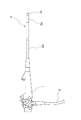
以下、図面に基づいて本発明の実施の形態について詳細に説明する。まず、図1に内視鏡の全体構成図を示し、図中において、1は本体操作部、2は体腔内等への挿入部、3はユニバーサルコードである。本体操作部1は術者等が手で把持して操作を行うためのものであり、挿入部2はこの本体操作部1に連設されている。挿入部2は、本体操作部1への連設部から大半の長さは挿入経路に沿って任意の方向に曲がる軟性部2aであって、この軟性部2aの先端にはアングル部2bが、さらにアングル部2bには先端硬質部2cがそれぞれ連設されている。アングル部2bは先端硬質部2cを所望の方向に向けるためのものであり、先端硬質部2cには体腔内の観察を行うための機構が設けられている。
【0013】
先端硬質部2cの先端面には、図2に示したように、観察窓10の両側に照明窓11,11が設けられている。これら1箇所の観察窓10及び2箇所の照明窓11,11は同一の平面で、両照明窓11は観察窓10からほぼ等しい距離だけ離間した位置に配置される。そして、観察窓10には、図3及び図4に示したように、観察手段12が装着され、また照明窓11には、図5に示したように、照明手段13が装着される。さらに、これらの他にも、先端硬質部2cの先端面には鉗子その他の処置具を導出させるための処置具導出口14が形成され、観察窓10に向けて洗浄用流体を供給するノズル15も設けられている。なお、以上の構成は、挿入部2の軸線方向に観察視野を向けた直視型内視鏡である。側視型内視鏡として構成する場合には、先端硬質部の側面に平坦面を形成して、前述した各部をこの平坦面に形成する。
【0014】
観察窓10に装着した観察手段12は、例えば図4に示したように、対物光学系20と撮像ユニット21とから構成される。対物光学系20は、本体ブロック22に装着したレンズ鏡筒22a内に設けた対物レンズ群23と、この対物レンズ群23の光軸を90°曲げるために、本体ブロック22に接着等の手段で固定したプリズム24とを有する。また、撮像ユニット21は、基板25に搭載したCCD等からなる固体撮像素子26を有するものであり、固体撮像素子26はプリズム24に接合固定され、その受光面は対物光学系20の結像位置に配置される。基板25には多数の配線が接続されており、この配線は途中で束ねられて1本のケーブル27としている。このケーブル27は挿入部2の内部から本体操作部1を経てユニバーサルコード3内に延在され、このユニバーサルコード3に設けた接続コネクタ(図示せず)を介してプロセッサに着脱可能に接続される。
【0015】
対物レンズ群23を構成するレンズのうち、1または複数枚からなる後群レンズは光軸方向に移動可能な可動レンズ23aである。観察窓10を観察対象部に近づけた時に、この可動レンズ23aを光軸方向に移動させると、観察対象部に対して正確にピントが合うように焦点調整を行うことができる。可動レンズ23aは、前群レンズを装着したレンズ鏡筒22aに対して独立のレンズ枠28に取り付けられており、このレンズ枠28は本体ブロック22に設けたガイド部22bに沿って光軸方向に移動するようになっている。レンズ枠28は、本体ブロック22のガイド部22bを貫通して駆動チャンバ22c内に延在されており、この駆動チャンバ22c内において、例えばヘリコイドねじ等からなるねじ軸29に螺合されている。ねじ軸29は本体ブロック22に連結して設けた支持部材30に回転自在に支持されている。ねじ軸29にはストッパ29aが設けられ、またねじ軸29の端部に連結部材31が設けられている。従って、ストッパ29aと連結部材31とで支持部材30を挟み込むことによって、ねじ軸29は回転のみが可能で、それ以外の方向に移動しないように保持される。さらに、ねじ軸29の先端にはストッパ機能を発揮するナット32が装着されており、レンズ枠28はナット32とストッパ29aとの間で往復移動できるようになる。
【0016】
ねじ軸29の基端部に連結した連結部材31にはフレキシブルシャフト33が連結されている。フレキシブルシャフト33は、例えば密着コイルからなり、左右両方向に回転することから、2重の密着コイルで構成される。また、フレキシブルシャフト33は、支持部材30に連結して設けた可撓性チューブ34内に挿通されており、これらフレキシブルシャフト33と可撓性チューブ34とでコントロールケーブルが構成される。コントロールケーブルは本体操作部1内にまで延在されており、可撓性チューブ34の基端部は固定的に保持される。フレキシブルシャフト33の基端部には、回転駆動手段としての正逆回転可能なモータ45(図6参照)が接続して設けられる。従って、モータを作動させて、フレキシブルシャフト33を可撓性チューブ34内で軸回りに回転させると、ねじ軸29が回転して可動レンズ23aを設けたレンズ枠28を光軸方向に所定のストローク分だけ移動させることができる。なお、フレキシブルシャフト33は手動操作で回転させるように構成することもできる。
【0017】
一方、図5に示したように、照明窓11には照明手段13が装着されており、この照明手段13はライトガイド35と照明レンズ36とから構成される。照明レンズ36は照明窓11に臨み、ライトガイド35の出射端が照明レンズ36に対面する状態に設けられる。ライトガイド35は極細い光学繊維を多数束ねたものから構成され、もって曲げ方向に可撓性を持たせる構成としている。このライトガイド35は挿入部2から本体操作部1を経てユニバーサルコード3内に延在され、光源用コネクタ(図示せず)を介して光源装置40に着脱可能に接続される。光源装置40は、図6に示したように、ライトガイド35の入射端が対向配設される光源ランプ41を有し、このライトガイド35の入射端と光源ランプ41との間には、光源ランプ41側から絞り42,コンデンサレンズ43,回転カラーフィルタ44が配置されている。
【0018】
照明窓11は観察窓10の左右両側に2箇所設けられる。ここで、照明窓11からの照明光は照明レンズ36を通過した後に所定の角度で発散する。観察窓10に設けた対物光学系20を構成する対物レンズ群23の可動レンズ23aを光軸方向に移動させることによって、数mm程度、例えば1〜2mmといった至近距離の位置の物体でも撮影できるようになっている。図6から明らかなように、フレキシブルシャフト34の基端部はモータ45に接続されている。このモータ45は本体操作部1内に設けられており、この本体操作部1はまたモータ45によるレンズ位置を制御するレンズ位置制御部46を備え、このレンズ位置制御部46は、例えば押しボタン式の操作子等を有し、本体操作部1を把持する手の指等で操作子等を操作して、モータ45を作動させて、可動レンズ23aを通常観察距離位置と最近接観察距離位置とに変位させるようにしている。なお、可動レンズ23aは、その移動ストロークの両端位置に配置されるだけでなく、このストロークの中間位置に配置した状態でも観察を行うことができるように設定することもできる。
【0019】
図7に最近接観察距離で観察する際において、観察窓10に設けた対物光学系20の観察視野と、照明窓11に設けた照明レンズ36の照明範囲との関係を示す。図中において、最近接観察距離をdとして、この最近接観察距離dだけ離れた観察対象部Sに対する対物光学系20の視野角をθとする。ここで、観察手段12は固体撮像素子26を有するものであるから、この固体撮像素子26で撮影した映像をモニタ画面に表示される表示領域をFとし、この表示領域Fの中心位置をCとする。この表示領域Fは対物光学系20の視野範囲とは異なり、実際の観察範囲である。つまり、モニタ画面に表示される映像は対物光学系20の視野のうち、その視野の中心位置を含む制限された範囲である。そして、内視鏡による観察像をモニタ画面に表示するに当って、画面の周囲の部分をマスクして表示領域を限定している。従って、表示領域Fは実際に画面に表示される画像の領域であり、画像処理を行う際にマスク処理が施される場合や、固体撮像素子26の撮像エリアをマスク部材で覆うようにして撮像範囲を限定する場合等にあっては、そのマスクの内部の領域が表示領域Fとなる。
【0020】
対物光学系20を設けた観察窓10の左右両側に、同じ距離だけ離れた位置の照明窓11に設けた照明レンズ36からの照明光は発散しながら観察対象部Sに向けて照射される。この照明窓11からの照明光において、光軸中心線Aに対して角度θ1 からの光が表示領域Fの中心Cに届き、また表示領域Fの端部には角度θ2 からの光が届く。そして、照明窓11からの照明光を観察対象部Sに照射した時に、その光軸中心線Aの位置が最も照度が高く、周辺に向かうに応じて連続的に照度が低くなる。照明レンズ36の位置が観察対象部Sに近くなればなるほど、照度分布はより急峻な変化を示すことになり、最近接観察距離dを数mmとしたときの観察対象部Sに対する照明光の照度分布は、図8に示したように、光軸中心線A乃至その近傍では極めて急激な変化が生じる。照明窓11は2箇所設けられており、観察対象部Sにおける表示領域Fは両照明窓11間に配置されているので、その中心C乃至その近傍の部位は2つの照明窓11,11からの光が照射される。この結果、表示領域Fを含む観察対象部Sにおける照明は、図8に二点鎖線で示したような照度分布を有するものとなる。
【0021】
図8から明らかなように、表示領域Fが一定であるとし、照明窓11の光軸中心線Aと表示領域Fの中心との間の距離をΔDとした時に、この距離ΔDを大きくすると、表示領域Fでの照明光の照度の変化が少なくなるが、照度そのものは低くなる。つまり、両照明窓11,11を観察窓10から遠ざければ遠ざけるほど、表示領域F内での照度変化が抑制されるが、全体的に暗くなる。これに対して、距離ΔDを小さくすると、つまり両照明窓11,11を観察窓10に近づけると、中心Cを含む表示領域F全体の照度が高くなるが、照度分布のうちの急峻な変化を示す部位の光が表示領域F内に取り込まれるので、表示領域Fの中心Cに対して、周辺部の照度の差が極めて大きくなる。
【0022】
ところで、観察手段12として固体撮像素子26を用いた場合、鮮明な画像を得るためには、表示領域Fの中心部分と端部との間の照度の差をできるだけ小さくする必要がある。最も暗い部位、つまり表示領域Fの中心Cの位置の照度に対して、最も明るい部位、つまり表示領域Fの端部の照度が概略2倍程度以下の差であれば、固体撮像素子26に必要な程度のダイナミックレンジを持たせるように調整して、S/N比の良好な画像が得られる。照度が2倍以上になると、プロセッサで感度補正等を行ったとしても、モニタ画面に表示される画像の画質が低下することになる。
【0023】
以上のように、表示領域F内において、照度の差が小さければ小さいほど画質が向上する。このためには、照明窓11を観察窓10から遠ざけて、照度分布のうちなだらかな変化を示す部分を利用する。ただし、照明窓11を観察窓10から遠ざけるには限度がある。このために、前述したマスクを照度分布の均一化のために利用する。即ち、マスクを行なうことによって、モニタ画面による表示領域Fの周辺部が限定することができ、照度差が2倍以下となる部位を表示端位置と設定することより、照度分布がなだらかな変化を示す部位のみを表示させることができる。ただし、表示領域Fの全体の照度が低下して画像全体が暗くなる。従って、表示領域F内での照度の差を極端に小さくしない方が望ましく、照度差が1.2倍以下になるように設定すると、表示領域Fの全体照度が十分でなくなる場合がある。具体的には、表示領域Fの中心と端部との照度差は2〜1.2倍、さらに望ましくは2〜1.5倍とし、最も望ましいのは概略1.8倍程度とする。
【0024】
表示領域Fの範囲及び照明レンズ36の発散角は予め定まっており、この状態で最近接観察距離dでの照度分布を前述した範囲内とするために、照明窓11,11と観察窓10との距離ΔDを調整する。しかも、モニタ画面に表示される表示領域Fをマスクの内部に限定している。その結果、最近接観察距離dにおける表示領域Fの中心Cに向かう角度θ1 からの光の照度が、表示領域Fの端部に向かう角度θ2 からの光の照度の2倍〜1.2倍、最も好ましくは1.8倍程度となるように距離ΔDを設定する。これによって、光源光量のロスを最小限に抑制し、かつ鮮明な画像を得ることができる。また、照度差がこの範囲となるように設定しても、最近接観察距離dより遠い位置の観察を行う際には、それに応じて照明レンズ36による各照明窓11からの照明光の発散度合いが大きくなり、観察対象部に照射される照明光の照度分布がより均一化されるので、鮮明な画像を得ることができる。
【0025】
このように、最近接観察距離dでの表示領域Fの中心Cと端部との間の照明光の照度差を少なくするためには、照明手段13からの照明光の照度分布における光軸中心線Aから離れ、照度そのものが低いところを利用しなければならないことになる。このために、光源ランプ41から通常観察距離時における照明光量と同じ光量の照明光を照射したのでは、表示領域F全体が暗くなってしまうおそれがある。この場合には、可動レンズ23aが最近接観察距離dに移動した時に、それをセンサ等で検出して自動的に光源光量を増大させるように制御するのが望ましい。
【0026】
図6から明らかなように、光源ランプ41からライトガイド35に入射される照明光の光量は可変となっており、このために絞り42は絞り駆動回路47により絞り量を可変にする構成となっている。この絞り駆動回路47は固体撮像素子26で得た画像信号のうちの輝度信号を自動光量制御回路48に取り込んで、この輝度信号のレベルに応じて最適な光量の照明光がライトガイド35に入射される。そこで、この自動光量制御回路48を利用して、可動レンズ23aが最近接観察距離dの位置に移動した時に、絞り42の開度を大きくして、ライトガイド35への入射光量を大きくする。このために、レンズ位置制御部46による操作信号が自動光量制御回路48に取り込まれて、可動レンズ23aが最近接観察距離dに変位した時に、絞り42の開口を大きくすることによって固体撮像素子26で表示領域Fの全体を鮮明な状態で撮影できる明るさとなる。
【0027】
ここで、光源光量を調整するのではなく、固体撮像素子26が接続されるプロセッサに設けたゲインコントローラにおけるゲイン値を変化させるように構成しても良い。また、レンズ位置制御部46を操作した時に、光源光量なりゲインコントローラなりを自動的に制御するようにしたが、観察対象部の状態、例えば光の反射率等の関係で、必ずしもこれらを制御しなくても、十分鮮明な画像が得られる場合もある。このような場合には、手動スイッチの操作で光源光量やゲイン値を変化させるように構成してもよい。
【0028】
また、図9に示したように、照明窓11,11間の位置に第3の照明手段50を設ける構成とすることもできる。この第3の照明手段50は、左右の照明窓の間に向けて補助的な照明光を照射するものである。第3の照明手段50には、ライトガイド35を分岐させて、その出射端がこの第3の照明手段50を構成する照明レンズに対面させている。このように、第3の照明手段50を設けることによって、表示領域Fの全体を明るくできるだけでなく、この第3の照明手段50の光軸中心線が表示領域Fの中心方向に向くように設定することによって、表示領域Fの全体照度の差をさらに抑制できる。この第3の照明手段50は、常時点灯状態にしても良いが、照明光を照射する状態と、照射しない状態とに切り換えることもできる。そして、可動レンズ23aが最近接観察距離となった時に、自動的にこの第3の照明手段50から照明光を照射する状態に切り換わる構成とするのが望ましい。なお、第3の照明手段としては、ライトガイドに代えて白色LED等他の発光手段を用いることもできる。
【0029】
さらに、観察対象部Sに照射されるのは照明窓11からの直接照明であるが、図10に示したように、挿入部2の先端構成部2cにフード51を装着する構成とすれば、照明光の照度の差をより緩和させることができる。このフード51は体腔内壁に当接させた状態とすることによって、最近接観察距離乃至その近傍で観察する際に、挿入部2の先端部分を安定させるために設けられるものである。そこで、体腔内壁にフード51の先端を当接させた状態で照明窓11から照明光を照射すると、この照明光は観察対象部Sから反射して、さらにフード51の内面で反射することになる。この結果、観察対象部Sに対しては、この反射光による間接照明も行われ、この間接照明は観察対象部のほぼ全面にわたって概略均一に照射されるようになる。従って、フード51の内面を白色の反射面とすることによって、より反射効率を高め、また間接照明の光量のばらつきを抑制するためには反射面を乱反射するように粗面とするのが望ましい。
【0030】
ここで、フード51の挿入部2からの突出長さとしては、最近接観察距離d以下にまで短くすると、フード51の先端を体腔内壁に当接させた時に、観察距離が最近接観察距離d以下になってしまう。ただし、フード51の突出長さは観察窓10に設けた対物レンズ群23による観察視野の妨げとなる。従って、フード51の突出長さは最近接観察距離dと同じか、またはそれより長く、しかも観察視野の妨げとならない程度の長さとする。
【0031】
【実施例】
図11にライトガイド35の先端に照明レンズ52を装着した構成を示す。ここで、この照明レンズ52は平凹レンズであって、その曲率半径は図示したように、R=1.713となっている。このレンズ構成において、d線に対する屈折率nd=1.55としたものを第1の実施例として、またnd=1.85としたものを第2の実施例として示す。さらに、図12に示したように、ライトガイド35の先端に設けられる照明レンズ53も平凹レンズからなり、その曲率半径はR=1.460であって、nd=1.55としたものを第3の実施例とし、またnd=1.85としたものを第4の実施例とする。
【0032】
さらにまた、図13に、ライトガイド50の出射端に、コアとクラッドからなり、光混合用の導光用ガラスロッド54を配置したものが示されている。この導光用ガラスロッド54の出射側は凸球面形状となっており、またその前方には両凸レンズ55aと平凸レンズ55bとからなる照明用組レンズ55を装着している。このようなレンズ構成を用いると、照明光は照明用組レンズ55の前方で一度収束した後に、発散するようになる。そこで、この構成において、導光用ガラスロッド54を構成するコアのndを1.62とし、クラッドのndを1.52となし、また照明用組レンズ55において、nd=1.55としたものを第5の実施例とし、またnd=1.85としたものを第6の実施例とする。なお、図13には、nd=1.85とした時において、ガラスロッド54に対して、その光軸に平行な光を入射した時の光線の光路が示されている。
【0033】
以上の各実施例における射出光角度分布の相対値は、下記表1に示したようになる。
【0034】
【表1】

【0035】
また、以上の表をグラフにプロットしたものが図14であり、またこの図14のグラフを対数表示すると、図15のようになる。従って、これら表1及び図14,図15のグラフから、1枚構成または組み合わせからなる照明レンズのそれぞれの配光特性に基づいて、観察窓10に対して、その両側に装着される照明窓11,11の位置を適宜決定すれば良い。つまり、図14において、光量が2倍以下となる2点を直線で結び、この線の長さをSとし、立ち上がり角をθとした時に、照明手段と観察手段との間隔はS・sinθとして設定される。
【0036】
【発明の効果】
以上説明したように、本発明は、観察手段の両側に照明手段を設けて、これら観察手段と両照明手段との間隔と、モニタ画面上での表示領域のマスクによる限定とによって、観察手段による観察領域の中心部における照度に対して周辺部が2倍以下の照度となるように設定しているので、極めて簡単な構成で、最近接観察距離で観察する際における観察領域の照度のばらつきを最小限に抑制できる等の効果を奏する。
【図面の簡単な説明】
【図1】内視鏡の全体構成図である。
【図2】挿入部の先端部分の外観図である。
【図3】挿入部の先端部分の断面図である。
【図4】観察手段の構成説明図である。
【図5】照明手段の構成説明図である。
【図6】照明及び観察機構の概略構成図である。
【図7】最近接観察距離で観察する際の観察窓の観察視野と照明窓からの照明範囲との関係を示す説明図である。
【図8】照明手段による照明光の最近接観察距離での照度分布を示す線図である。
【図9】第3の照明手段を設けた例を示す挿入部の先端面の外観図である。
【図10】フードを装着させた状態での図2と同様の断面図である。
【図11】第1,第2の実施例におけるライトガイドと照明レンズとを示す構成説明図である。
【図12】第3,第4の実施例におけるライトガイドと照明レンズとを示す構成説明図である。
【図13】第5,第6の実施例におけるライトガイドと照明レンズとを示す構成説明図である。
【図14】各実施例の照明レンズを用いた場合における配光分布を示す線図である。
【図15】図14の線図を対数表示した図である。
【符号の説明】
1 本体操作部 2 挿入部
2c 先端硬質部 10 観察窓
11 照明窓 12 観察手段
13 照明手段 20 対物光学系
21 撮像ユニット 23 対物レンズ群
23a 可動レンズ 26 固体撮像素子
29 ねじ軸 33 フレキシブルシャフト
34 可撓性チューブ 35 ライトガイド
3652,53 照明レンズ 40 光源装置
41 光源ランプ 42 絞り
46 レンズ位置制御部 47 絞り駆動回路
48 自動光量制御回路 50 第3の照明手段
51 フード 54 導光用ガラスロッド
55 照明用組レンズ[0001]
BACKGROUND OF THE INVENTION
The present invention relates to an endoscope used for medical purposes and the like equipped with observation means having an objective lens having a variable observation distance.
[0002]
[Prior art]
An endoscope is inserted into a patient's body, etc., and is used for observing the inside of a body cavity, etc., and is inserted into a body operation part, etc., which is operated by a surgeon and the like. And an insertion portion. Since the inside of a body cavity or the like is a dark place, it is necessary to perform illumination from the outside in order to perform the observation. Therefore, the illumination unit and the observation unit are provided at a substantially flush surface at the distal end of the insertion portion. The illumination means uses a light guide in which ultrafine optical fibers are bundled as illumination light transmission means, and has a configuration in which an illumination lens for diverging illumination light is provided at the exit end of the light guide, and the observation means has an objective lens. Then, an image inside the body cavity is formed by this objective lens. An image guide made of an optical fiber bundle faces the image formation position of this objective lens, and a solid-state image pickup device made up of a CCD or the like is placed at the image formation position, and the optical image of the observation target portion is converted into an electrical signal. There are some that are converted to. The former is an optical endoscope, and observation inside a body cavity is performed by observing an eyepiece connected to a main body operation unit. The latter is a so-called electronic endoscope, which transmits an electrical signal from the solid-state imaging means to a processor and processes the processor to generate a video signal. The monitor is attached to the processor. This video is displayed.
[0003]
When observing in a body cavity using an endoscope, for example, in the stomach, in addition to performing observation at a position where the observation means is separated from the inner wall of the stomach, for example, this body cavity is used to more accurately inspect the body cavity wall. There are also cases where observation is performed from a close position with respect to the wall. As described above, for example, Japanese Patent Publication No. Sho 61-53698 discloses a configuration having a focus adjustment mechanism that adjusts the focus of the objective lens so that the focus of the objective lens is accurately adjusted when observing from a close position. As a focus adjustment mechanism, there is one that can be adjusted to be in focus at a very close position, such as 1 cm or less, particularly 1 mm to 2 mm, from the inner wall of the body cavity. Thus, by enabling observation at a close distance, the inner wall of the body cavity can be inspected with higher accuracy.
[0004]
By the way, even if the focus of the objective lens constituting the observation means is adjusted so as to be accurately aligned with the observation target portion, accurate observation is not always possible. As already explained, since the inside of the body cavity is a dark place, illumination is performed by illumination means including a light guide and an illumination lens. Don't be. If a dark part is generated in a part of the observation area by the observation means, observation becomes difficult. Further, if a part of the observation area is extremely bright as compared with the other parts, the difference in brightness in the entire observation area becomes large, which also hinders observation. In particular, in the case of an electronic endoscope using a solid-state image sensor, if there is an excessively bright part, some pixels in the solid-state image sensor become saturated, blooming or smearing occurs, and illumination If the illuminance of the light is uneven, the dynamic range is lowered even if the pixels are not saturated, and an image with good image quality cannot be obtained.
[0005]
A technique for suppressing illumination unevenness with respect to the observation region of the observation means is disclosed in, for example, Japanese Patent Laid-Open No. 6-169879. According to this prior art, two illumination means are installed at positions separated by an equal distance on both sides of the observation means mounting portion provided at the distal end of the insertion portion. It is configured to irradiate illumination light with substantially the same amount of light. In this case, in order to concentrate the illumination light as much as possible in the observation region in the observation target portion, the two illumination means are arranged as close to the observation means as possible under the condition that no harmful light enters the observation means. Has been.
[0006]
[Problems to be solved by the invention]
By the way, it is necessary to make the insertion portion of the endoscope as small as possible from the viewpoint of insertion operability, patient pain reduction, and the like because of the insertion into the body cavity. Moreover, it is not only the one observation means and the two illumination means that are provided in the insertion portion having such a small diameter. For example, a treatment instrument insertion channel for inserting forceps and other treatment instruments may be provided, and a mechanism for ejecting a cleaning fluid toward the observation means may be provided. Therefore, due to the installation space, the aperture diameter in the illumination means provided at two locations is extremely small, and is substantially close to a point light source. However, an illumination lens is provided facing the exit end of the light guide, and the illumination light is diverged by this illumination lens. As a result, if the inner wall of the body cavity that is the observation target part is separated from the illumination unit by a certain distance, the observation region by the observation unit is illuminated with substantially uniform illuminance. However, when the observation distance is short, the illumination lens cannot sufficiently diverge light. Especially when the observation means illuminates the observation target portion from a very close position such that the observation means is only a few mm away from the observation target portion, and only about 1-2 mm, the illuminance at the center position of the illumination window is extremely high. An illuminance distribution is generated in which the illuminance rapidly decreases as it goes to the periphery.
[0007]
From the above, even if the illumination means is arranged on both sides of the observation means as in the prior art, the observation distance is somewhat large as long as the two illumination means are arranged at positions close to the observation means. In some cases, it is advantageous for concentrating the illumination light on the observation area, but when observing at the closest observation distance such as an observation distance of 1 cm or less, particularly several mm, the center position of the observation area and the peripheral portion The difference in illuminance between them becomes extremely large. As a result, particularly when photographing with a solid-state image sensor, the illuminance at the peripheral portion is too high, and the pixel at that position may be saturated and blooming, smear, etc. may occur, and the dynamic range is reduced, resulting in S / N. The ratio is lowered, and a clear image cannot be displayed on the monitor screen, and the accuracy of inspection and diagnosis is deteriorated.
[0008]
The present invention has been made in view of the above points. The object of the present invention is to minimize the variation in illuminance in the observation region when observing at the closest observation distance with a very simple configuration. There is.
[0009]
[Means for Solving the Problems]
In order to achieve the above-described object, the present invention provides at least two illuminating means on the substantially same plane of the distal end of the insertion portion, and one observation means at a position between these illuminating means, The illumination means includes a light guide and an illumination lens that diverges illumination light from the light guide, and the observation means includes at least an objective lens whose observation distance is variable,In an endoscope observation apparatus that displays an image from this observation means on a monitor screen,The illumination means is located on both sides of the observation means.The monitor screen is arranged at a position separated from the observation means by a predetermined distance, and the display range of the monitor screen is limited by a mask, and when observing at the closest observation distance by the observation means, The display end position set by the mask with respect to the illuminance at the center of the observation area is set so that the illuminance is twice or less.It is the feature.
[0010]
here,In the display on the monitor screen, the periphery including the center of the observation area and the display edge positionIt is desirable that the difference in illuminance is as small as possible. However, the amount of illumination light has a Gaussian distribution having a peak at the center of the optical axis of the illumination lens. Therefore, when a portion where the change in the amount of light is substantially flat is used, the amount of light applied to the observation target portion is extremely small, and the entire obtained image becomes dark. Therefore, the lower limit of the difference in illuminance between the central portion and the peripheral portion of the observation region is 1.2 times.here,The position where the illuminance does not exceed twice the illuminance of the illumination light at the center of the observation area is the peripheral area of the area where the monitor screen image is displayed. That is, the peripheral part of the observation area is not the peripheral part of the field of view of the objective lens itself but the end part of the display area of the observation target part on the monitor screen.In the case of a configuration including a solid-state imaging device as an observation means,When the solid-state image sensor or monitor screen is masked, set the illuminance at the mask boundary to not exceed twice the illuminance at the center.Do. Longest observation distanceIf you do not adopt the configuration described above,The illuminance distribution can be made uniform by the action of the illumination lens. Therefore, a distance of 1 cm or less at which the light diverging effect of the illumination lens cannot be sufficiently exhibited,In particular, when the closest observation position is several mm, an image with a good image quality can be obtained by configuring the present invention to make the illuminance distribution uniform.
[0011]
If the difference in illuminance between the central portion and the peripheral portion of the observation area is to be made as small as possible, the illuminance of the illumination light is lower when observing at the closest observation distance than when observing at the normal observation distance. In general, a light source device is provided with means for changing the illuminance by providing a light source light quantity adjusting means such as a diaphragm. Therefore, when observing at the closest observation distance position, it is desirable to control the illumination to be brightened by the illuminance changing means. It is also possible to provide a third lighting unit between the two lighting units and to function as the illuminance changing unit. In particular, when a forward / reverse rotation motor is used as the objective lens drive means for adjusting the focal position, a switch that operates when the objective lens is displaced to the closest observation distance position by the forward / reverse rotation motor is provided. Thus, the third lighting means can be controlled to blink in conjunction with this switch. Furthermore, the gain amount of the gain controller can be controlled to be larger when observing at the closest observation distance than when observing at the normal observation distance. There is a configuration in which the hood surrounding the observation means and the illumination means is fitted and provided at the distal end of the insertion portion, but in this case, if the inner surface of the hood is a reflection surface of the illumination light, In addition to alleviating variations in the illuminance of the illumination light from the illumination means, the observation target portion can be illuminated more brightly. In this case, it is desirable that the protruding length from the distal end of the insertion portion of the hood is equal to or slightly longer than the closest observation distance.
[0012]
DETAILED DESCRIPTION OF THE INVENTION
Hereinafter, embodiments of the present invention will be described in detail with reference to the drawings. First, FIG. 1 shows an overall configuration diagram of an endoscope. In the figure, 1 is a main body operation unit, 2 is an insertion unit into a body cavity or the like, and 3 is a universal cord. The main
[0013]
As shown in FIG. 2,
[0014]
The observation means 12 attached to the
[0015]
Of the lenses constituting the
[0016]
A
[0017]
On the other hand, as shown in FIG. 5, an
[0018]
Two
[0019]
FIG. 7 shows the relationship between the observation visual field of the objective
[0020]
Illumination light from the
[0021]
As is apparent from FIG. 8, when the display area F is constant and the distance between the optical axis center line A of the
[0022]
By the way, when the solid-
[0023]
As described above, in the display area F, the smaller the difference in illuminance, the better the image quality. For this purpose, the
[0024]
The range of the display area F and the divergence angle of the
[0025]
Thus, in order to reduce the illuminance difference of the illumination light between the center C and the end of the display area F at the closest observation distance d, the optical axis center in the illuminance distribution of the illumination light from the illumination means 13 is used. A place where the illuminance itself is low away from the line A must be used. For this reason, if the illumination light of the same amount as the illumination light amount at the normal observation distance is irradiated from the
[0026]
As can be seen from FIG. 6, the amount of illumination light incident on the
[0027]
Here, instead of adjusting the light source light amount, a gain value in a gain controller provided in a processor to which the solid-
[0028]
Moreover, as shown in FIG. 9, it can also be set as the structure which provides the 3rd illumination means 50 in the position between the
[0029]
Furthermore, although it is direct illumination from the
[0030]
Here, when the protrusion length of the
[0031]
【Example】
FIG. 11 shows a configuration in which the
[0032]
Furthermore, FIG. 13 shows a
[0033]
The relative values of the emission light angle distribution in each of the above examples are as shown in Table 1 below.
[0034]
[Table 1]
[0035]
Further, FIG. 14 is a plot of the above table on a graph, and FIG. 15 is a logarithmic display of the graph of FIG. Therefore, from the graphs in Table 1 and FIGS. 14 and 15, the
[0036]
【The invention's effect】
As described above, the present invention provides illumination means on both sides of the observation means, and the distance between these observation means and both illumination means.And by limiting the display area on the monitor screenSince the illuminance at the center of the observation area by the observation means is set so that the illuminance at the periphery is twice or less, the illuminance of the observation area when observing at the closest observation distance with a very simple configuration It is possible to minimize the variation of the above.
[Brief description of the drawings]
FIG. 1 is an overall configuration diagram of an endoscope.
FIG. 2 is an external view of a distal end portion of an insertion portion.
FIG. 3 is a cross-sectional view of a distal end portion of an insertion portion.
FIG. 4 is a diagram illustrating the configuration of observation means.
FIG. 5 is an explanatory diagram of a configuration of an illumination unit.
FIG. 6 is a schematic configuration diagram of an illumination and observation mechanism.
FIG. 7 is an explanatory diagram showing the relationship between the observation field of view of the observation window and the illumination range from the illumination window when observing at the closest observation distance.
FIG. 8 is a diagram showing the illuminance distribution at the closest observation distance of the illumination light by the illumination means.
FIG. 9 is an external view of the distal end surface of the insertion portion showing an example in which third illumination means is provided.
FIG. 10 is a cross-sectional view similar to FIG. 2 with a hood attached.
FIG. 11 is a configuration explanatory view showing a light guide and an illumination lens in the first and second embodiments.
FIG. 12 is a configuration explanatory view showing a light guide and an illumination lens in the third and fourth embodiments.
FIG. 13 is a structural explanatory view showing a light guide and an illumination lens in the fifth and sixth embodiments.
FIG. 14 is a diagram showing a light distribution in the case where the illumination lens of each example is used.
15 is a logarithmic display of the diagram of FIG.
[Explanation of symbols]
1 Main
11
13 Illumination means 20 Objective optical system
21
23a
29
34
3652, 53
41
46 Lens
48 Automatic light
51
55 Assembly lens for lighting
Claims (10)
前記照明手段は前記観察手段の両側位置で、この観察手段から所定の距離だけ離間した位置に配置され、かつ前記モニタ画面の表示範囲は、マスクにより限定されるようになっており、
前記観察手段により最近接観察距離で観察する時に、前記観察領域の中心部における照度に対して前記マスクにより設定された表示端位置が2倍以下の照度になるように設定されることを
特徴とする内視鏡の観察装置。At least two illuminating means are provided on the substantially same plane at the tip of the insertion portion, and one observation means is provided at a position between the two illuminating means. Each illuminating means includes a light guide and a light guide. In an endoscope observation apparatus comprising: an illumination lens that diverges illumination light; and the observation means includes at least an objective lens having a variable observation distance, and an image from the observation means is displayed on a monitor screen. ,
The illuminating means is disposed at both sides of the observing means, at a position separated from the observing means by a predetermined distance, and the display range of the monitor screen is limited by a mask,
When observing at the closest observation distance by the observation means, the display end position set by the mask is set to be less than twice the illuminance at the central portion of the observation area. /> A characteristic endoscope observation apparatus.
Priority Applications (1)
| Application Number | Priority Date | Filing Date | Title |
|---|---|---|---|
| JP13295799A JP3661487B2 (en) | 1998-05-18 | 1999-05-13 | Endoscope observation device |
Applications Claiming Priority (3)
| Application Number | Priority Date | Filing Date | Title |
|---|---|---|---|
| JP10-135008 | 1998-05-18 | ||
| JP13500898 | 1998-05-18 | ||
| JP13295799A JP3661487B2 (en) | 1998-05-18 | 1999-05-13 | Endoscope observation device |
Publications (2)
| Publication Number | Publication Date |
|---|---|
| JP2000037345A JP2000037345A (en) | 2000-02-08 |
| JP3661487B2 true JP3661487B2 (en) | 2005-06-15 |
Family
ID=26467410
Family Applications (1)
| Application Number | Title | Priority Date | Filing Date |
|---|---|---|---|
| JP13295799A Expired - Fee Related JP3661487B2 (en) | 1998-05-18 | 1999-05-13 | Endoscope observation device |
Country Status (1)
| Country | Link |
|---|---|
| JP (1) | JP3661487B2 (en) |
Families Citing this family (12)
| Publication number | Priority date | Publication date | Assignee | Title |
|---|---|---|---|---|
| JP2001346752A (en) * | 2000-06-09 | 2001-12-18 | Asahi Optical Co Ltd | Endoscope for close-up magnification observation |
| JP2002119467A (en) * | 2000-08-07 | 2002-04-23 | Fuji Photo Optical Co Ltd | Endoscope |
| US7123288B2 (en) | 2001-09-28 | 2006-10-17 | Fujinon Corporation | Electronic endoscope eliminating influence of light distribution in optical zooming |
| JP4363843B2 (en) | 2002-03-08 | 2009-11-11 | オリンパス株式会社 | Capsule endoscope |
| JP4554267B2 (en) * | 2004-04-27 | 2010-09-29 | オリンパス株式会社 | Endoscope and endoscope system |
| WO2013035522A1 (en) * | 2011-09-08 | 2013-03-14 | オリンパスメディカルシステムズ株式会社 | Endoscope |
| EP3000378B1 (en) | 2013-05-22 | 2017-11-22 | Olympus Corporation | Endoscope |
| EP3096176A4 (en) | 2014-01-15 | 2018-01-03 | Olympus Corporation | Endoscope device |
| WO2016014581A1 (en) * | 2014-07-21 | 2016-01-28 | Endochoice, Inc. | Multi-focal, multi-camera endoscope systems |
| JP6407044B2 (en) * | 2015-01-26 | 2018-10-17 | 富士フイルム株式会社 | Endoscope device |
| JP6257853B2 (en) | 2015-10-20 | 2018-01-10 | オリンパス株式会社 | Endoscope |
| WO2017130524A1 (en) * | 2016-01-29 | 2017-08-03 | オリンパス株式会社 | Endoscope |
-
1999
- 1999-05-13 JP JP13295799A patent/JP3661487B2/en not_active Expired - Fee Related
Also Published As
| Publication number | Publication date |
|---|---|
| JP2000037345A (en) | 2000-02-08 |
Similar Documents
| Publication | Publication Date | Title |
|---|---|---|
| CN102727162B (en) | Electronic endoscope and electronic endoscope system | |
| US6251068B1 (en) | Endoscopic observation system | |
| US6582362B2 (en) | Endoscope system | |
| JP4850315B2 (en) | Endoscope apparatus and endoscope | |
| US11583163B2 (en) | Endoscope system for adjusting ratio of distributing primary light to first illuminator and second illuminator | |
| US20120253121A1 (en) | Electronic endoscope | |
| CN101426414B (en) | endoscope | |
| JP3661487B2 (en) | Endoscope observation device | |
| JP5292428B2 (en) | Endoscope system | |
| CN104507376B (en) | endoscope | |
| JP2010063485A (en) | Illumination optical system for endoscope and endoscope | |
| JPWO2019012794A1 (en) | Endoscope and imaging unit | |
| JP3083353B2 (en) | Endoscope device | |
| JPH0141964B2 (en) | ||
| JPH05253184A (en) | Drum-membrane observing device | |
| JP3412514B2 (en) | Endoscope observation device | |
| JPH03109515A (en) | Automatic light control device | |
| JP2001087217A (en) | Endoscope | |
| CN120379579A (en) | Scene self-adaptive endoscope illuminator | |
| JP5639522B2 (en) | Electronic endoscope system | |
| JP2003235789A (en) | Observing instrument for endoscope | |
| JPH0413112A (en) | Endoscope device | |
| JPS63287813A (en) | Endoscope device | |
| JP2001128931A (en) | Lighting system for endoscope | |
| JP4365627B2 (en) | Optical observation probe and endoscope observation apparatus |
Legal Events
| Date | Code | Title | Description |
|---|---|---|---|
| A977 | Report on retrieval |
Free format text: JAPANESE INTERMEDIATE CODE: A971007 Effective date: 20040520 |
|
| A131 | Notification of reasons for refusal |
Free format text: JAPANESE INTERMEDIATE CODE: A131 Effective date: 20040608 |
|
| A521 | Written amendment |
Free format text: JAPANESE INTERMEDIATE CODE: A523 Effective date: 20040809 |
|
| TRDD | Decision of grant or rejection written | ||
| A01 | Written decision to grant a patent or to grant a registration (utility model) |
Free format text: JAPANESE INTERMEDIATE CODE: A01 Effective date: 20050301 |
|
| A61 | First payment of annual fees (during grant procedure) |
Free format text: JAPANESE INTERMEDIATE CODE: A61 Effective date: 20050314 |
|
| R150 | Certificate of patent or registration of utility model |
Ref document number: 3661487 Country of ref document: JP Free format text: JAPANESE INTERMEDIATE CODE: R150 Free format text: JAPANESE INTERMEDIATE CODE: R150 |
|
| FPAY | Renewal fee payment (event date is renewal date of database) |
Free format text: PAYMENT UNTIL: 20090401 Year of fee payment: 4 |
|
| R250 | Receipt of annual fees |
Free format text: JAPANESE INTERMEDIATE CODE: R250 |
|
| FPAY | Renewal fee payment (event date is renewal date of database) |
Free format text: PAYMENT UNTIL: 20090401 Year of fee payment: 4 |
|
| FPAY | Renewal fee payment (event date is renewal date of database) |
Free format text: PAYMENT UNTIL: 20100401 Year of fee payment: 5 |
|
| R250 | Receipt of annual fees |
Free format text: JAPANESE INTERMEDIATE CODE: R250 |
|
| S111 | Request for change of ownership or part of ownership |
Free format text: JAPANESE INTERMEDIATE CODE: R313113 |
|
| FPAY | Renewal fee payment (event date is renewal date of database) |
Free format text: PAYMENT UNTIL: 20100401 Year of fee payment: 5 |
|
| R350 | Written notification of registration of transfer |
Free format text: JAPANESE INTERMEDIATE CODE: R350 |
|
| FPAY | Renewal fee payment (event date is renewal date of database) |
Free format text: PAYMENT UNTIL: 20110401 Year of fee payment: 6 |
|
| R250 | Receipt of annual fees |
Free format text: JAPANESE INTERMEDIATE CODE: R250 |
|
| R250 | Receipt of annual fees |
Free format text: JAPANESE INTERMEDIATE CODE: R250 |
|
| FPAY | Renewal fee payment (event date is renewal date of database) |
Free format text: PAYMENT UNTIL: 20120401 Year of fee payment: 7 |
|
| FPAY | Renewal fee payment (event date is renewal date of database) |
Free format text: PAYMENT UNTIL: 20130401 Year of fee payment: 8 |
|
| R250 | Receipt of annual fees |
Free format text: JAPANESE INTERMEDIATE CODE: R250 |
|
| FPAY | Renewal fee payment (event date is renewal date of database) |
Free format text: PAYMENT UNTIL: 20130401 Year of fee payment: 8 |
|
| FPAY | Renewal fee payment (event date is renewal date of database) |
Free format text: PAYMENT UNTIL: 20140401 Year of fee payment: 9 |
|
| R250 | Receipt of annual fees |
Free format text: JAPANESE INTERMEDIATE CODE: R250 |
|
| R250 | Receipt of annual fees |
Free format text: JAPANESE INTERMEDIATE CODE: R250 |
|
| R250 | Receipt of annual fees |
Free format text: JAPANESE INTERMEDIATE CODE: R250 |
|
| R250 | Receipt of annual fees |
Free format text: JAPANESE INTERMEDIATE CODE: R250 |
|
| R250 | Receipt of annual fees |
Free format text: JAPANESE INTERMEDIATE CODE: R250 |
|
| R250 | Receipt of annual fees |
Free format text: JAPANESE INTERMEDIATE CODE: R250 |
|
| LAPS | Cancellation because of no payment of annual fees |