JP3578058B2 - Multiplex communication system - Google Patents
Multiplex communication system Download PDFInfo
- Publication number
- JP3578058B2 JP3578058B2 JP2000212217A JP2000212217A JP3578058B2 JP 3578058 B2 JP3578058 B2 JP 3578058B2 JP 2000212217 A JP2000212217 A JP 2000212217A JP 2000212217 A JP2000212217 A JP 2000212217A JP 3578058 B2 JP3578058 B2 JP 3578058B2
- Authority
- JP
- Japan
- Prior art keywords
- frame
- network
- event
- activation
- relay device
- Prior art date
- Legal status (The legal status is an assumption and is not a legal conclusion. Google has not performed a legal analysis and makes no representation as to the accuracy of the status listed.)
- Expired - Lifetime
Links
Images


Classifications
-
- H—ELECTRICITY
- H04—ELECTRIC COMMUNICATION TECHNIQUE
- H04L—TRANSMISSION OF DIGITAL INFORMATION, e.g. TELEGRAPHIC COMMUNICATION
- H04L12/00—Data switching networks
- H04L12/02—Details
- H04L12/12—Arrangements for remote connection or disconnection of substations or of equipment thereof
-
- H—ELECTRICITY
- H04—ELECTRIC COMMUNICATION TECHNIQUE
- H04L—TRANSMISSION OF DIGITAL INFORMATION, e.g. TELEGRAPHIC COMMUNICATION
- H04L12/00—Data switching networks
- H04L12/28—Data switching networks characterised by path configuration, e.g. LAN [Local Area Networks] or WAN [Wide Area Networks]
- H04L12/46—Interconnection of networks
-
- Y—GENERAL TAGGING OF NEW TECHNOLOGICAL DEVELOPMENTS; GENERAL TAGGING OF CROSS-SECTIONAL TECHNOLOGIES SPANNING OVER SEVERAL SECTIONS OF THE IPC; TECHNICAL SUBJECTS COVERED BY FORMER USPC CROSS-REFERENCE ART COLLECTIONS [XRACs] AND DIGESTS
- Y02—TECHNOLOGIES OR APPLICATIONS FOR MITIGATION OR ADAPTATION AGAINST CLIMATE CHANGE
- Y02D—CLIMATE CHANGE MITIGATION TECHNOLOGIES IN INFORMATION AND COMMUNICATION TECHNOLOGIES [ICT], I.E. INFORMATION AND COMMUNICATION TECHNOLOGIES AIMING AT THE REDUCTION OF THEIR OWN ENERGY USE
- Y02D30/00—Reducing energy consumption in communication networks
- Y02D30/50—Reducing energy consumption in communication networks in wire-line communication networks, e.g. low power modes or reduced link rate
Landscapes
- Engineering & Computer Science (AREA)
- Computer Networks & Wireless Communication (AREA)
- Signal Processing (AREA)
- Small-Scale Networks (AREA)
Description
【0001】
【発明の属する技術分野】
本発明は多重通信システムに関し、特にイベント発生時におけるネットワーク間の中継制御に関する。
【0002】
【従来の技術】
近年、特にコンピュータ技術の進歩を背景として情報通信の高度化が進んでおり、例えば自動車においても、搭載される電装品等を制御する制御部の間でやり取りされる情報量は急速に増大している。そこで情報を伝達するワイヤーハーネスの数を低減すべく多重通信システムが採用されつつある。
【0003】
多重通信システムは、共通の多重通信線に、データフレームの送受信を行う制御用ECU等のノードが接続されたもので、ノード間で多重通信線を介してデータ通信を行う。制御の種類が多岐にわたる上記自動車等の場合には、データ通信を効率よく行うために、要求される通信速度の相違等に応じて複数のノード群に分けて複数のネットワークを形成し、属するネットワークが異なるノード間の通信はデータ中継装置を介して行う。
【0004】
また、通常、ネットワークの各ノードは、自ノードが属するネットワークは起動すべき旨のデータフレーム(以下、ウェイクアップフレームという)により、イベント等の起動要因が生じたことを認識するとともに、自ノードが起動状態にあることを他のノードに認識せしめる。すなわち、起動要因が生じたノードが先ずウェイクアップフレームをネットワークの通信線上へ送信し、これに呼応して他のノードが起動するとともに前記通信線にウェイクアップフレームを送信する。一方、ネットワーク、したがってすべてのノードは、消費電力を最低限に抑えるため、所定時間、起動要因がなければスリープ作動に入る。
【0005】
このため、あるノードにおいてイベントが発生し、その発生を所定の送信先に通知するイベント発生通知(以下、イベントフレーム)の中継が必要な場合、データ中継装置がイベントフレームを受信したとしても、送信先のネットワークがスリープ作動しているときには、イベントフレームを必ずしも送信先ノードが受信できるとは限らない。これは、キーレス式のドアロックやドアオープン等のようにイベントフレームが単発でしか送信されないものではきわめて不都合である。
【0006】
受信漏れの回避を図った技術として、エンジン始動期等のような通信システムの不安定期において、イベントの発生があるとイベントフレームを周期的に多数回送信することで、送信先における受信の確度を高めたものがある(特許第2904304号)。
【0007】
【発明が解決しようとする課題】
しかしながら、前記特許第2904304号のように送信する回数を多くしても確実に受信されるという保証はないし、送信回数を多く設定した場合、イベントが同時に多発すると、通信を徒に混雑させる。また、イベントの発生から送信先のノードがイベントの発生を認識するまでの遅延時間がイベントの発生状況に大きく左右される。
【0008】
また、イベント発生通知をデータ中継装置のバッファに蓄積したまま、送信先のネットワークが起動するまでデータ中継装置にて送信を保留することも考えられるが、結局、バッファの容量によっては十分な効果を得ることができず、徒に記憶容量を大きくしてもコストが上昇するばかりである。
【0009】
本発明は上記実情に鑑みなされたもので、イベントの発生が各ノードに通知されるまでの遅延時間がイベントの発生状況に大きく左右されず、遅延時間の短縮を図ることができる多重通信システムを提供することを目的とする。
【0010】
【課題を解決するための手段】
請求項1記載の発明では、通信線にノードが接続されてなる複数のネットワークと、該複数のネットワーク間でデータフレームを中継するデータ中継装置とを具備する多重通信システムにおいて、
前記ノードを、イベントの発生に応じてイベント発生通知を前記データ中継装置を介して送信するに際し、前記データ中継装置に対し、予め設定した所定の応答の送信を要求する送信要求を送信し、前記応答を受信すると前記イベント発生通知を送信する構成とする。
前記データ中継装置を、
前記ノードから前記送信要求を受信すると、少なくとも前記イベント発生通知の送信先の前記ネットワークに属するノードは起動すべき旨の起動要求を送信する起動要求送信手段と、
前記起動要求の送信先のネットワークに属するノードが起動状態にあるか否かを判定する起動状態判定手段と、
該起動状態判定手段により前記起動要求の送信先のネットワークに属する複数のすべてのノードが起動状態にあると判定されると、前記応答を少なくとも前記送信要求が送信された前記ネットワークに送信する応答送信手段とを具備する構成とする。
【0011】
イベント発生通知を送信するに先立ち、確実にその送信先ネットワークに属する複数のすべてのノードが起動状態となるので、イベント発生通知が確実に中継される。また送信先のネットワークに属するノードが起動していないという理由でイベント発生通知をデータ中継装置に待機させる必要がなく、バッファの容量が過大になることはなく低コストである。
【0012】
また、イベント発生により送信される前記送信要求、それに対する応答、起動要求はネットワークやノードの数等の構成により略固定的であるから、通信負荷は一定しており、また、イベントの発生から送信先のノードがイベントの発生を認識するまでの遅延時間がイベントの発生状況に左右されることもない。ここで、イベント発生通知の送信先のネットワークに属する複数のすべてのノードが起動した旨は、前記応答を一時に通知することから、ネットワークに属するノード数で多重通信線の負荷が増減することもない。
【0013】
請求項2記載の発明では、請求項1の発明の構成において、前記ノードを、自ノードが属する前記ネットワークに属するノードは起動すべき旨のデータフレームを前記送信要求として送信する構成とする。
前記起動要求送信手段を、少なくとも前記送信要求が送信された前記ネットワーク以外の前記ネットワークに前記起動要求を送信する構成とする。
【0014】
送信要求として、自ノードが属する前記ネットワークに属するノードは起動すべき旨のデータフレームが送信され、データ中継装置は、イベント発生通知の送信先となる可能性のあるすべてのネットワークに属するノードを起動せしめるので、イベントの発生したノードがイベント発生通知の送信先を特定可能なデータフレームを送信することなく、イベント発生通知の送信先を起動せしめることができる。したがって、データ中継装置において、イベント発生時に特別のプログラムを実行する必要もないから、プログラムを格納するROMの容量等、構成の簡略化を図ることができる。
【0015】
【発明の実施の形態】
(第1実施形態)
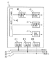
図1に本発明の第1実施形態になる多重通信システムを示す。多重通信システムは、複数(図例では3)のネットワーク11,12,13とデータ中継装置4とにより構成される。これらのネットワーク11〜13は、例えば自動車の車内制御用であれば、オーディオユニットECUやナビゲーションユニットECU等が接続されたオーディオ系ネットワーク、エンジンECUやエアコンECU等が接続されたボデー系ネットワークである。
【0016】
各ネットワーク11〜13は、多重通信線21,22,23にノードであるECU▲1▼311〜ECU▲9▼333(以下、適宜、ECU▲1▼〜ECU▲9▼のそれぞれを単にECUという)が接続されたもので、ECU▲1▼311〜ECU▲9▼333間でBEAN等の所定の通信プロトコルにてデータを送受信するようになっている(以下、適宜、第1の多重通信線21をBUS−A21と、第2の多重通信線22をBUS−B22と、第3の多重通信線23をBUS−C23という)。図例では第1のネットワーク11のBUS−A21にはECU▲1▼311、ECU▲2▼312、ECU▲3▼313が接続され、第2のネットワーク12のBUS−B22にはECU▲4▼321、ECU▲5▼322、ECU▲6▼323が接続され、第3のネットワーク13のBUS−C23にはECU▲7▼331、ECU▲8▼332、ECU▲9▼333が接続される。
【0017】
各ECU311〜333はI/O回路を備えており(ECU▲7▼331のみ図示)、その入力変化すなわちイベントが発生すると、イベントの内容に応じてイベント発生通知であるイベントフレームを前記データ中継装置4を介して送信し、イベントが発生した旨を通知する。各ECU311〜333はイベントフレームの送信に際し、前記データ中継装置4に対し、後述する所定の応答(BUS−Aフレーム、BUS−Bフレーム、BUS−Cフレーム)の送信を要求する送信要求であるウェイクアップフレームを送信し、前記応答を受信すると前記イベントフレームを送信する構成となっている。
【0018】
多重通信線21〜23は、データ中継装置4と接続され、データ中継装置4が、あるネットワーク11〜13から送信されたデータフレームを別のネットワーク11〜13に中継するようになっている。データ中継装置4はまた、各ネットワーク11〜13に属するノードのひとつとして所定のデータフレームを独自に送信するようになっている。
【0019】
図2にデータ中継装置4の構成を示す。データ中継装置4は通信用LSIや制御用のマイクロコンピュータ等で構成されたもので、図はその機能ブロックで表してある。データ中継装置4は、3つのフレーム送受信部411,412,413を備えており、フレーム送受信部411〜413は多重通信線21〜23と1対1に接続されている。
【0020】
第1〜第3のフレーム送受信部411〜413が受信したデータフレームは受信フレーム格納バッファ42に一時格納される。受信フレーム格納バッファ42はRAMの所定領域が割り当てられる。格納されたデータフレームは、中継するものであれば中継処理部43が送信を担当するフレーム送受信部411〜413を特定し、フレーム送受信部411〜413に出力される。そして所定のタイミングで送信される。
【0021】
また、格納されたデータフレームがウェイクアップフレームであれば、起動要求送信部44がすべてのフレーム送信部411〜413からウェイクアップフレームを送信する。
【0022】
また、前記ウェイクアップフレームを受信すると起動状態判定部45が、次いで送信される各ECU311〜333からのウェイクアップフレームの受信の有無を受信フレーム格納バッファ42に格納されたデータフレームから判じる。そして、各ネットワーク11〜13について、その属するすべてのECU311〜333からのウェイクアップフレームを受信したと判定すると、起動状態応答部46が、当該ネットワークが起動した旨のデータフレームをすべてのフレーム送信部411〜413から送信する。ネットワークが起動した旨を通知するデータフレームは、以下、適宜、ネットワーク起動通知フレームといい、また、第1のネットワーク11のBUS−A12と接続されたすべてのECU▲1▼311〜ECU▲3▼313が起動した旨の通知についてはBUS−Aフレーム、第2のネットワーク22のBUS−B12と接続されたすべてのECU▲4▼321〜ECU▲6▼323が起動した旨の通知についてはBUS−Bフレーム、第3のネットワーク13のBUS−C23と接続されたすべてのECU▲7▼331〜ECU▲9▼333が起動した旨の通知についてはBUS−Cフレームともいうものとする。
【0023】
図3は第3のネットワーク13に属するECU▲7▼331のI/O回路3311において第1のネットワーク11に通知すべきイベントが発生した場合のECU▲7▼331の作動を示すもので、先ず、前記イベント発生を受けてウェイクアップし(ステップS101)、ウェイクアップフレームを送信する(ステップS102)。この時、BUS−C23に接続されたデータ中継装置4もノードのひとつとしてウェイクアップフレームを受信しウェイクアップする。
【0024】
次いで、データ中継装置4が送信する、第1のネットワーク11がウェイクアプした旨を通知するBUS−Aフレームの受信待ちとなり(ステップS103)、受信すると、イベントフレームを送信する(ステップS103)。イベントフレームは、所定の通信プロトコルにしたがって生成され、その内容により発生したイベントを特定できるとともに送信先が特定できるようになっている。
【0025】
図4は起動時からのデータ中継装置4の作動を示すもので、先ず、データ中継装置4が接続された多重通信線21〜23のうちのいずれでウェイクアップフレームを受信すると、例えば、前記ECU▲7▼331のウェイクアップフレームの受信でウェイクアップし(ステップS201)、起動要求送信部44が、すべての多重通信線21〜23にウェイクアップフレームを送信する(ステップS202)。
【0026】
次いで、起動状態判定部45が、BUS−A21と接続されたすべてのECU▲1▼311〜ECU▲3▼313のウェイクアップフレームを受信したか否かを判断し(ステップS203)、受信されていれば、起動状態応答部46が、すべての多重通信線21〜23にBUS−Aフレームを送信する(ステップS204)。ステップS203ですべてのウェイクアップフレームが受信されていなければ、ステップS204をスキップする。
【0027】
次いで、起動状態判定部45が、BUS−B22と接続されたすべてのECU▲4▼321〜ECU▲6▼323のウェイクアップフレームを受信したか否かを判断し(ステップS205)、受信されていれば、起動状態応答部46が、すべての多重通信線21〜23にBUS−Bフレームを送信する(ステップS206)。ステップS205ですべてのウェイクアップフレームが受信されていなければ、ステップS206をスキップする。
【0028】
次いで、起動状態判定部45が、BUS−C23と接続されたすべてのECU▲7▼331〜ECU▲9▼333のウェイクアップフレームを受信したか否かを判断し(ステップS207)、受信されていれば、起動状態応答部46が、すべての多重通信線21〜23にBUS−Cフレームを送信する(ステップS208)。ステップS207ですべてのウェイクアップフレームが受信されていなければ、ステップS208をスキップする。
【0029】
次いで、中継処理部43が、中継すべきデータフレーム、例えば、前記イベントフレームを受信したか否かを判断し(ステップS209)、受信していれば中継先に受信フレームを送信する(ステップS210)。
【0030】
なお、起動状態でイベントが発生した場合、各ECU311〜333は前記ステップS102〜S104と同様の手順を実行し、データ中継装置4は前記ステップS202〜S210と同様の手順を実行する。
【0031】
図5により、イベントが発生した時の本多重通信システムの各部における作動を説明する。なお、以下の説明において、イベントは、ECU▲7▼331のI/O回路3311で発生したものとし、イベントフレームはBUS−A21に接続されたノードに送信すべきものとして説明する。
【0032】
第3のネットワーク13に属するECU▲7▼331は、イベントの発生により起動し、ウェイクアップフレーム(図中、WakeUp)を送信する。これにより、BUS−C23に接続されたデータ中継装置4、ECU▲8▼332、ECU▲9▼333が起動し、それぞれウェイクアップフレームを送信する。この時、データ中継装置4は、第1、第2ネットワーク11,12にもウェイクアップフレームを送信する。
【0033】
これにより、第1ネットワーク11のECU▲1▼311〜ECU▲3▼313が起動して、それぞれウェイクアップフレームを送信する。一方、第1ネットワーク12のECU▲4▼321、ECU▲5▼322、ECU▲6▼323が起動し、それぞれウェイクアップフレームを送信する。
【0034】
データ中継装置4は、ECU▲7▼331に続いてECU▲8▼332、ECU▲9▼333のウェイクアップフレームを受信すると、すべてのネットワーク11〜13に第3ネットワーク13が起動した旨のBUS−Cフレームを送信する。ECU▲1▼311、ECU▲2▼312、ECU▲3▼313のウェイクアップフレームを受信すると、すべてのネットワーク11〜13に第1ネットワーク11が起動した旨のBUS−Aフレームを送信する。ECU▲4▼321、ECU▲5▼322、ECU▲6▼323のウェイクアップフレームを受信すると、すべてのネットワーク11〜13に第2ネットワーク12が起動した旨のBUS−Bフレームを送信する。各ネットワーク11〜13の各ECU311〜333はこれらのネットワーク起動通知フレームから他のネットワーク11〜13が起動したことを認識する。
【0035】
ここで、BUS−AフレームをECU▲7▼331が受信すると、ECU▲7▼331はこの時点でイベントフレームを送信する。このイベントフレームはデータ中継装置4により受信され第1ネットワーク11に送信される。そして、送信先のノードがこれを受信しイベントの発生を認識する。
【0036】
本発明によれば、少なくともイベントフレームは送信先のネットワークが起動してから送信される。したがって、確実に送信先に中継される。また送信先のネットワークが起動していないおそれがある、という理由でイベントフレームをデータ中継装置に待機させる必要がないので、バッファの容量が過大になることはなく低コストである。
【0037】
また、イベント発生からイベントフレームが送信先に中継されるまでに送信されるデータフレームは図5に示したデータフレームより多くなることはなく、通信負荷は一定しており、また、イベントの発生から送信先のノードがイベントの発生を認識するまでの遅延時間がイベントの発生状況に左右されることもない。
【0038】
また、イベントフレームの送信先のネットワークが起動した旨、すなわち送信先のネットワークに属するノードが起動した旨は、ネットワーク起動通知フレームにより一時に通知され、ネットワークに属するノード数で多重通信線の負荷が増減することはなく、ノード数によってイベントの発生を認識するまでの遅延時間が左右されることもない。
【0039】
また、データ中継装置は、ノードからウェイクアップフレームを受信するとすべてのネットワークにウェイクアップフレームを送信し、これにより各ネットワークが起動すると、該ネットワークが起動した旨を順次、送信している。これにより、イベントが発生したノードは、データ中継装置にイベントフレームの送信先が認識できるようなデータフレームを送信しなくとも、イベントフレームの送信先のネットワークが起動したことを知ることができる。すなわち、データ中継装置においては、ウェイクアップフレームを受信した時にはイベント発生とは関係なく同じプログラムを実行すればよい。また、イベントフレームの送信先を認識できるようなデータフレームが不要な分、データフレームの種類が少なくて済む。したがって、プログラムを格納するROMの容量等、構成の簡略化を図ることができる。
【0040】
なお、以上の作動説明はECU▲7▼331のI/O回路3311においてイベントが発生し、それを第1ネットワーク11に送信するとして説明したが、イベントの発生したECU311〜333や、イベントフレームの中継先のネットワークが異なっても同様である。
【0041】
また、イベントフレームは、その中継先ネットワークが複数(図例では2)の場合は、BUS−Aフレーム〜BUS−Cフレームのうち、当該複数のネットワークについてのものが受信された時点で前記複数のネットワークを中継先として指定し送信する。あるいは、該当するネットワークについてのネットワーク起動通知フレームがそれぞれ受信され次第、順次、イベントフレームを当該ネットワークに向けて送信するのでもよい。
【0042】
また、各ECU311〜333は起動状態においてイベントが発生した場合でも、ウェイクアップフレームを送信し、これに応答してデータ中継装置4は各ネットワーク11〜13にウェイクアップフレームを送信する。しかして起動状態であると否とによらず、イベントフレームが確実に中継される。
【0043】
(第2実施形態)
図6、図7に第2の実施形態の構成を示す。第1実施形態では、各ECUはイベントフレームの送信に先立ってウェイクアップフレームを送信し、データ中継装置は、このウェイクアップフレームの受信をもってイベントフレームの中継の可能性ありと判じ、すべてのネットワークにウェイクアップフレームを送信し、ネットワークが起動すると、順次、対応するネットワーク起動通知フレームを送信する。そして中継の必要なイベントが発生したノードは、前記ネットワーク起動通知フレームのいずれかにより、イベントフレームを送信すべき送信先のネットワークが起動したことを知るわけであるが、本実施形態は、イベントの発生したECUがウェイクアップフレームとは別のデータフレームを送信することで、イベントフレームを確実に中継し得る状態を整えるものである。なお、本実施形態の基本的な構成は第1実施形態のものと同一であり、第1実施形態との相違点を中心に説明する。
【0044】
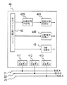
多重通信システムは、多重通信線21にノードとしてのECU▲1▼341、ECU▲2▼342、ECU▲3▼343が接続されて第1のネットワーク14を形成し、多重通信線22にノードとしてのECU▲4▼351、ECU▲5▼352、ECU▲6▼353が接続されて第2のネットワーク15を形成し、多重通信線23にノードとしてのECU▲7▼361、ECU▲8▼362、ECU▲9▼363が接続されて第3のネットワーク16を形成しており、各ネットワーク14〜16間はデータ中継装置4Aによりデータ中継がなされる構成となっている。
【0045】
各ECU341〜363は、イベントフレームの中継が必要なイベントの発生時は、イベントフレームの送信に先立ち、データ中継装置4Aに、送信要求である起動判定要求フレームを送信する。この起動判定要求フレームは、ネットワーク起動通知フレームの送信をデータ中継装置4Aに対して要求するもので、データ中継装置4Aにおいて、ネットワーク起動通知フレームの送信を要求する旨が認識されるとともに、どのネットワーク14〜16についてのネットワーク起動通知フレームを要求するものであるかが認識されるように、所定の通信プロトコルにしたがって構成されている。
【0046】
各ECU341〜363は、起動判定要求フレームの送信後は該当するネットワーク起動通知フレームの受信待ちとなる。受信されればイベントフレームを送信する。
【0047】
なお、イベント発生時に、イベントが発生したECU341〜363が属するネットワーク14〜16が起動していなければ、前記起動判定要求フレームの送信に先立ち、先ずウェイクアップフレームを送信して自ネットワーク14〜16を起動状態にしてデータ中継装置4Aとの通信を可能にしておく。
【0048】
データ中継装置4Aは、第1実施形態のデータ中継装置において、起動要求送信部、起動状態判定部、起動状態応答部の機能を別の機能に代えたもので、起動要求送信部44Aは、受信した起動判定要求フレームから、ネットワーク起動通知フレームの送信を要求する旨、対象となるネットワーク14〜16を抽出し、該当するネットワーク14〜16にウェイクアップフレームを送信する。
【0049】
起動状態判定部45Aは、該当ネットワーク14〜16の通信線21〜23上の変化を監視して、該当ネットワーク14〜16のすべてのECU341〜363からウェイクアップフレームを受信したか否かにより該当ネットワーク14〜16が起動したか否かを判断する。
【0050】
起動状態応答部46Aは、前記起動判定要求フレームを送信したネットワーク14〜16に、BUS−AフレームないしBUS−Cフレームのうち、前記該当ネットワーク14〜16についてのものを送信する。
【0051】
かかる構成でも、イベントフレームが確実に送信先に中継され、データ中継装置のバッファの容量が過大になることはなく低コストである。
【0052】
また、イベント発生からイベントフレームが送信先に中継されるまでの通信負荷は一定しており、通信負荷がイベントの発生状況で左右されることもない。
【0053】
また、送信先のネットワークに属するノードが起動した旨は、ネットワーク起動通知フレームにより一時に通知され、イベントの発生から送信先のECUがイベントの発生を認識するまでの遅延時間がノード数で左右されることもない。
【0054】
しかも、イベントフレームの送信先のネットワークについてのネットワーク起動通知フレームだけが送信されるから、ネットワーク数が多い場合に有利である。
【0055】
(第3実施形態)
図8、図9に第3の実施形態の構成を示す。基本的な構成は第1、第2実施形態のものと同一であり、第1、第2実施形態との相違点を中心に説明する。各ECUおよびデータ中継装置が、イベント発生時の条件に応じて、第1実施形態における制御と第2実施形態における制御を選択的に実行するようにしたものである。なお基本的な構成は第1、第2実施形態のものと同一であり、第1、第2実施形態との相違点を中心に説明する。
【0056】
多重通信システムは、多重通信線21にノードとしてのECU▲1▼371、ECU▲2▼372、ECU▲3▼373が接続されて第1のネットワーク17を形成し、多重通信線22にノードとしてのECU▲4▼381、ECU▲5▼382、ECU▲6▼383が接続されて第2のネットワーク18を形成し、多重通信線23にノードとしてのECU▲7▼391、ECU▲8▼392、ECU▲9▼393が接続されて第3のネットワーク19を形成しており、各ネットワーク17〜19間はデータ中継装置4Bによりデータ中継がなされる構成となっている。
【0057】
各ECU371〜ECU399はスリープ状態においてイベントが発生した時は第1実施形態と同様に送信要求であるウェイクアップフレームを送信して、これに対するデータ中継装置4Bからの応答として前記BUS−Aフレーム〜BUS−Cフレームを順次、受信し、該当するネットワーク起動通知フレームを受信した時点でイベントフレームを送信する。一方、起動状態でイベントが発生した時は第2実施形態と同様に送信要求である起動判定要求フレームを送信して、これに対するデータ中継装置4Bからの応答として前記BUS−AフレームないしBUS−Cフレームの該当するものを受信し、イベントフレームを送信する。
【0058】
データ中継装置4Bは、第1、第2実施形態のデータ中継装置において、起動要求送信部、起動状態判定部、起動状態応答部の機能を別の機能に代えたもので、起動要求送信部44Bは、スリープ作動時にウェイクアップフレームを受信した時は、第1実施形態と同様にすべてのネットワーク17〜19にウェイクアップフレームを送信する。また、起動状態において起動判定要求フレームを受信した時は、第2実施形態と同様に該当するネットワーク17〜19にウェイクアップフレームを送信する。
【0059】
起動状態判定部45Bは、起動要求送信部44Bがすべてのネットワーク17〜19にウェイクアップフレームを送信した場合には、各ネットワーク17〜19の通信線21〜23上の変化を監視して、各ネットワーク17〜19に属するすべてのECU371〜393からウェイクアップフレームを受信したか否かにより各ネットワーク17〜19が起動したか否かを判断する。一方、起動要求送信部44Bが、起動判定要求フレームにより特定される該当ネットワーク17〜19にウェイクアップフレームを送信した場合には、該当ネットワーク17〜19の通信線21〜23上の変化を監視して、該当ネットワーク17〜19のすべてのECU371〜393からウェイクアップフレームを受信したか否かにより該当ネットワーク17〜19が起動したか否かを判断する。
【0060】
起動状態応答部46Bは、ネットワーク起動通知フレームの応答を要求するウェイクアップフレームまたは起動判定要求フレームを送信したネットワーク17〜19に、起動状態判定部45Bが起動状態と判断したネットワーク17〜19についてのネットワーク起動通知フレームを送信する。
【0061】
かかる構成でも、イベントフレームが確実に送信先に中継され、データ中継装置のバッファの容量が過大になることはなく低コストである。
【0062】
また、イベント発生からイベントフレームが送信先に中継されるまでの通信負荷は一定しており、通信負荷がイベントの発生状況で左右されることもない。
【0063】
また、送信先のネットワークに属するノードが起動した旨は、ネットワーク起動通知フレームにより一時に通知され、イベントの発生から送信先のECUがイベントの発生を認識するまでの遅延時間がノード数で左右されることもない。
【0064】
しかも、スリープ状態においてイベントが発生した時は、データ中継装置4Bが起動判定要求フレームを待つことなくウェイクアップフレームに呼応して各ネットワーク17〜19にウェイクアップフレームを送信するので、イベント発生からイベントフレーム送信までの遅延時間を短縮することができる。一方、起動状態においてイベントが発生した時は起動判定要求フレームが送信され、データ中継装置4Bは必要なネットワーク17〜19についてのみネットワーク起動通知フレームを送信するので、通信負荷を減じることができる。
【図面の簡単な説明】
【図1】本発明の第1の多重通信システムの構成図である。
【図2】前記多重通信システムのデータ中継装置の構成図である。
【図3】前記多重通信システムのECUの作動を示すフローチャートである。
【図4】前記データ中継装置の作動を示すフローチャートである。
【図5】前記多重通信システムの各部の作動を示すタイミングチャートである。
【図6】本発明の第2の多重通信システムの構成図である。
【図7】前記多重通信システムのデータ中継装置の構成図である。
【図8】本発明の第3の多重通信システムの構成図である。
【図9】前記多重通信システムのデータ中継装置の構成図である。
【符号の説明】
11,12,13,14,15,16,17,18,19 ネットワーク
21,22,23 多重通信線
311,312,313,321,322,323,331,332,333
,341,342,343,351,352,353,361,362,363
,371,372,373,381,382,383,391,392,393
ノード
4,4A,4B データ中継装置
44,44A,44B 起動要求送信部(起動要求送信手段)
45,45A,45B 起動状態判定部(起動状態判定手段)
46,46A,46B 起動状態応答部(起動状態応答手段)[0001]
TECHNICAL FIELD OF THE INVENTION
The present invention relates to a multiplex communication system, and more particularly to relay control between networks when an event occurs.
[0002]
[Prior art]
In recent years, in particular, the advancement of computer technology has led to the advancement of information communication. For example, even in automobiles, the amount of information exchanged between control units that control mounted electric components and the like has rapidly increased. I have. Therefore, multiplex communication systems are being adopted to reduce the number of wire harnesses for transmitting information.
[0003]
In the multiplex communication system, a node such as a control ECU for transmitting and receiving data frames is connected to a common multiplex communication line, and data communication is performed between the nodes via the multiplex communication line. In the case of the above-mentioned automobiles and the like having various types of control, in order to perform data communication efficiently, a plurality of networks are formed by dividing into a plurality of nodes according to a difference in required communication speed and the like, However, communication between different nodes is performed via a data relay device.
[0004]
Normally, each node of the network recognizes that an activation factor such as an event has occurred by a data frame (hereinafter, referred to as a wake-up frame) indicating that the network to which the own node belongs should be activated. Make other nodes recognize that it is running. That is, the node in which the activation factor has occurred first transmits a wake-up frame to the communication line of the network, and in response to this, activates another node and transmits a wake-up frame to the communication line. On the other hand, the network, and thus all nodes, enter sleep mode for a predetermined period of time without any wake-up factor in order to minimize power consumption.
[0005]
Therefore, when an event occurs in a certain node and it is necessary to relay an event occurrence notification (hereinafter, referred to as an event frame) for notifying the occurrence to a predetermined destination, even if the data relay device receives the event frame, the When the previous network is sleeping, the destination node cannot always receive the event frame. This is extremely inconvenient if the event frame is transmitted only once, such as a keyless door lock or door open.
[0006]
As a technique to avoid reception omission, during an unstable period of a communication system such as an engine start period, when an event occurs, an event frame is periodically transmitted many times, thereby improving the accuracy of reception at a transmission destination. There is an enhanced one (Japanese Patent No. 2904304).
[0007]
[Problems to be solved by the invention]
However, even if the number of transmissions is increased, there is no guarantee that the reception is reliable even if the number of transmissions is increased, and if the number of transmissions is set to a large number, if the events occur frequently at the same time, the communication will be crowded. In addition, the delay time from the occurrence of an event until the destination node recognizes the occurrence of the event greatly depends on the occurrence state of the event.
[0008]
It is also conceivable to suspend the transmission in the data relay device until the network of the transmission destination is started while the event occurrence notification is stored in the buffer of the data relay device. However, a sufficient effect may be obtained depending on the capacity of the buffer. It cannot be obtained, and even if the storage capacity is increased, the cost only increases.
[0009]
SUMMARY OF THE INVENTION The present invention has been made in view of the above circumstances, and a multiplex communication system capable of reducing a delay time until a delay time until the occurrence of an event is notified to each node is not largely influenced by an event occurrence state. The purpose is to provide.
[0010]
[Means for Solving the Problems]
According to the first aspect of the present invention, in a multiplex communication system including a plurality of networks each having a node connected to a communication line, and a data relay device that relays a data frame between the plurality of networks,
The node, when transmitting an event occurrence notification via the data relay device in response to the occurrence of an event, to the data relay device, transmits a transmission request requesting transmission of a predetermined response set in advance, When the response is received, the event occurrence notification is transmitted.
The data relay device,
Upon receiving the transmission request from the node, at least a node belonging to the network to which the event occurrence notification is transmitted is a start request transmitting unit that transmits a start request indicating that the node should be started,
Activation state determination means for determining whether a node belonging to the network to which the activation request is transmitted is in an activation state,
The By the starting state judgment means Belongs to the destination network of the activation request Multiple all Node is up Is determined to be And a response transmitting means for transmitting the response to at least the network to which the transmission request has been transmitted.
[0011]
Before sending an event notification, make sure it belongs to the destination network Multiple all Since the node is in the activated state, the event occurrence notification is reliably relayed. In addition, there is no need to cause the data relay device to wait for an event occurrence notification because the node belonging to the transmission destination network has not been activated, so that the buffer capacity does not become excessive and the cost is low.
[0012]
Further, since the transmission request, response thereto, and activation request transmitted upon occurrence of an event are substantially fixed depending on the configuration of the network and the number of nodes, etc., the communication load is constant. The delay time until the previous node recognizes the occurrence of the event does not depend on the occurrence state of the event. Here, it belongs to the destination network of the event occurrence notification. Multiple all The fact that the node has started is notified of the response at one time, so that the load on the multiplex communication line does not increase or decrease depending on the number of nodes belonging to the network.
[0013]
According to a second aspect of the present invention, in the configuration of the first aspect of the present invention, the node corresponds to the network to which the own node belongs. Nodes belonging to Is configured to transmit a data frame to be activated as the transmission request.
The activation request transmission unit transmits the activation request to at least the network other than the network to which the transmission request has been transmitted.
[0014]
As the transmission request, the network to which the own node belongs Nodes belonging to Is transmitted, a data frame indicating that the event should be activated is transmitted to the data relay device. Nodes belonging to Is started, the destination of the event occurrence notification can be started without transmitting the data frame that allows the node where the event has occurred to specify the destination of the event occurrence notification. Therefore, in the data relay device, there is no need to execute a special program when an event occurs, so that the configuration such as the capacity of the ROM for storing the program can be simplified.
[0015]
BEST MODE FOR CARRYING OUT THE INVENTION
(1st Embodiment)
FIG. 1 shows a multiplex communication system according to a first embodiment of the present invention. The multiplex communication system includes a plurality (three in the example in the figure) of
[0016]
Each of the
[0017]
Each of the
[0018]
The
[0019]
FIG. 2 shows the configuration of the
[0020]
The data frames received by the first to third frame transmission /
[0021]
If the stored data frame is a wake-up frame, the activation
[0022]
When the wake-up frame is received, the activation
[0023]
FIG. 3 shows the operation of the ECU <b> 7 331 when an event to be notified to the
[0024]
Next, it waits for reception of a BUS-A frame transmitted from the
[0025]
FIG. 4 shows the operation of the
[0026]
Next, the activation
[0027]
Next, the activation
[0028]
Next, the activation
[0029]
Next, the
[0030]
When an event occurs in the activated state, each of the
[0031]
The operation of each unit of the multiplex communication system when an event occurs will be described with reference to FIG. In the following description, it is assumed that the event has occurred in the I / O circuit 3311 of the ECU 7 and that the event frame is to be transmitted to the node connected to the BUS-
[0032]
The ECU (7) 331 belonging to the
[0033]
As a result, the ECU (1) 311 to the ECU (3) 313 of the
[0034]
When the
[0035]
Here, when the ECU 7 331 receives the BUS-A frame, the ECU 7 331 transmits an event frame at this time. This event frame is received by the
[0036]
According to the present invention, at least the event frame is transmitted after the destination network is activated. Therefore, it is reliably relayed to the destination. Also, since there is no need to make the data relay device wait for the event frame because the network of the transmission destination may not be activated, the buffer capacity does not become excessive and the cost is low.
[0037]
Further, the number of data frames transmitted from the occurrence of the event until the event frame is relayed to the destination does not become larger than the data frame shown in FIG. 5, and the communication load is constant. The delay time until the destination node recognizes the occurrence of the event does not depend on the occurrence state of the event.
[0038]
In addition, the fact that the destination network of the event frame has been activated, that is, the fact that the nodes belonging to the destination network have been activated, is temporarily notified by a network activation notification frame, and the load of the multiplex communication line is reduced by the number of nodes belonging to the network. There is no increase or decrease, and the delay time until the occurrence of the event is recognized does not depend on the number of nodes.
[0039]
Further, when the data relay device receives the wake-up frame from the node, the data relay device transmits the wake-up frame to all the networks, and when each network is activated by this, the data relay device sequentially transmits that the networks are activated. As a result, the node in which the event has occurred can know that the network to which the event frame has been transmitted has been started without transmitting a data frame to the data relay device so that the transmission destination of the event frame can be recognized. That is, in the data relay device, when the wake-up frame is received, the same program may be executed regardless of the occurrence of the event. In addition, since there is no need for a data frame capable of recognizing a destination of an event frame, the number of types of data frames can be reduced. Therefore, the configuration such as the capacity of the ROM for storing the program can be simplified.
[0040]
In the above description of the operation, an event has occurred in the I / O circuit 3311 of the ECU <b> 7 331, and the event is transmitted to the
[0041]
In the case where the number of relay destination networks is two or more (2 in the example in the figure), the event frame includes the plurality of BUS-A frames to BUS-C frames at the time when the frames for the plurality of networks are received. Specify the network as a relay destination and send. Alternatively, an event frame may be sequentially transmitted to the network as soon as a network activation notification frame for the relevant network is received.
[0042]
Each of the
[0043]
(2nd Embodiment)
6 and 7 show the configuration of the second embodiment. In the first embodiment, each ECU transmits a wake-up frame prior to transmission of an event frame, and the data relay device determines that there is a possibility of relaying the event frame upon reception of the wake-up frame, and all the network relay devices transmit the wake-up frame. When the network is started, the corresponding network start notification frame is sequentially transmitted. Then, the node in which the event requiring the relay has occurred knows that the network of the transmission destination to which the event frame is to be transmitted has been activated by one of the network activation notification frames. The generated ECU transmits a data frame different from the wake-up frame to prepare a state in which the event frame can be reliably relayed. Note that the basic configuration of the present embodiment is the same as that of the first embodiment, and a description will be given focusing on differences from the first embodiment.
[0044]
In the multiplex communication system, ECU 1 341,
[0045]
Each of the
[0046]
After transmitting the activation determination request frame, each of the
[0047]
At the time of occurrence of the event, if the
[0048]
The
[0049]
The activation
[0050]
The activation
[0051]
Even in such a configuration, the event frame is reliably relayed to the transmission destination, and the buffer capacity of the data relay device does not become excessive and the cost is low.
[0052]
Further, the communication load from the occurrence of the event to the relay of the event frame to the destination is constant, and the communication load does not depend on the event occurrence situation.
[0053]
In addition, the fact that a node belonging to the destination network has been activated is notified at a time by a network activation notification frame, and the delay time from the occurrence of an event until the destination ECU recognizes the occurrence of the event depends on the number of nodes. Never even.
[0054]
Moreover, since only the network activation notification frame for the destination network of the event frame is transmitted, it is advantageous when the number of networks is large.
[0055]
(Third embodiment)
8 and 9 show the configuration of the third embodiment. The basic configuration is the same as that of the first and second embodiments, and the description will focus on differences from the first and second embodiments. Each ECU and the data relay device selectively execute the control according to the first embodiment and the control according to the second embodiment in accordance with conditions at the time of event occurrence. Note that the basic configuration is the same as that of the first and second embodiments, and the description will focus on the differences from the first and second embodiments.
[0056]
In the multiplex communication system, ECU 1 371,
[0057]
When an event occurs in the sleep state, each of the
[0058]
The
[0059]
When the activation request transmission unit 44B transmits a wake-up frame to all the networks 17 to 19, the activation
[0060]
The activation
[0061]
Even in such a configuration, the event frame is reliably relayed to the transmission destination, and the buffer capacity of the data relay device does not become excessive and the cost is low.
[0062]
Further, the communication load from the occurrence of the event to the relay of the event frame to the destination is constant, and the communication load does not depend on the event occurrence situation.
[0063]
In addition, the fact that a node belonging to the destination network has been activated is notified at a time by a network activation notification frame, and the delay time from the occurrence of an event until the destination ECU recognizes the occurrence of the event depends on the number of nodes. Never even.
[0064]
Moreover, when an event occurs in the sleep state, the
[Brief description of the drawings]
FIG. 1 is a configuration diagram of a first multiplex communication system of the present invention.
FIG. 2 is a configuration diagram of a data relay device of the multiplex communication system.
FIG. 3 is a flowchart showing an operation of an ECU of the multiplex communication system.
FIG. 4 is a flowchart showing an operation of the data relay device.
FIG. 5 is a timing chart showing the operation of each unit of the multiplex communication system.
FIG. 6 is a configuration diagram of a second multiplex communication system of the present invention.
FIG. 7 is a configuration diagram of a data relay device of the multiplex communication system.
FIG. 8 is a configuration diagram of a third multiplex communication system of the present invention.
FIG. 9 is a configuration diagram of a data relay device of the multiplex communication system.
[Explanation of symbols]
11, 12, 13, 14, 15, 16, 17, 18, 19 Network
21, 22, 23 Multiplexed communication line
311, 312, 313, 321, 322, 323, 331, 332, 333
, 341,342,343,351,352,353,361,362,363
, 371, 372, 373, 381, 382, 383, 391, 392, 393
node
4,4A, 4B data relay device
44, 44A, 44B Activation request transmission unit (activation request transmission means)
45, 45A, 45B activation state determination unit (activation state determination means)
46, 46A, 46B Activation state response section (Activation state response means)
Claims (2)
前記ノードを、イベントの発生に応じてイベント発生通知を前記データ中継装置を介して送信するに際し、前記データ中継装置に対し、予め設定した所定の応答の送信を要求する送信要求を送信し、前記応答を受信すると前記イベント発生通知を送信する構成とし、
前記データ中継装置を、
前記ノードから前記送信要求を受信すると、少なくとも前記イベント発生通知の送信先の前記ネットワークに属するノードは起動すべき旨の起動要求を送信する起動要求送信手段と、
前記起動要求の送信先のネットワークに属するノードが起動状態にあるか否かを判定する起動状態判定手段と、
該起動状態判定手段により前記起動要求の送信先のネットワークに属する複数のすべてのノードが起動状態にあると判定されると、前記応答を少なくとも前記送信要求が送信された前記ネットワークに送信する応答送信手段とを具備する構成としたことを特徴とする多重通信システム。In a multiplex communication system including a plurality of networks in which a plurality of nodes are connected to a communication line and a data relay device that relays a data frame between the plurality of networks,
The node, when transmitting an event occurrence notification via the data relay device in response to the occurrence of an event, to the data relay device, transmits a transmission request requesting transmission of a predetermined response set in advance, When the response is received, the event occurrence notification is transmitted,
The data relay device,
Upon receiving the transmission request from the node, at least a node belonging to the network to which the event occurrence notification is transmitted is a start request transmitting unit that transmits a start request indicating that the node should be started,
Activation state determination means for determining whether a node belonging to the network to which the activation request is transmitted is in an activation state,
When the activation state determination means determines that all the nodes belonging to the network to which the activation request is transmitted are in the activated state, a response transmission for transmitting the response to at least the network to which the transmission request has been transmitted. Multiplex communication system characterized by comprising:
前記起動要求送信手段を、少なくとも前記送信要求が送信された前記ネットワーク以外の前記ネットワークに前記起動要求を送信する構成とした多重通信システム。The multiplex communication system according to claim 1, wherein the node transmits the data frame indicating that a node belonging to the network to which the node belongs to be activated as the transmission request,
A multiplex communication system, wherein the activation request transmission unit transmits the activation request to at least the network other than the network to which the transmission request has been transmitted.
Priority Applications (2)
| Application Number | Priority Date | Filing Date | Title |
|---|---|---|---|
| JP2000212217A JP3578058B2 (en) | 2000-07-13 | 2000-07-13 | Multiplex communication system |
| US09/877,028 US6967969B2 (en) | 2000-07-13 | 2001-06-11 | Multiplex communication system capable of activating destination network beforehand |
Applications Claiming Priority (1)
| Application Number | Priority Date | Filing Date | Title |
|---|---|---|---|
| JP2000212217A JP3578058B2 (en) | 2000-07-13 | 2000-07-13 | Multiplex communication system |
Publications (2)
| Publication Number | Publication Date |
|---|---|
| JP2002026957A JP2002026957A (en) | 2002-01-25 |
| JP3578058B2 true JP3578058B2 (en) | 2004-10-20 |
Family
ID=18708165
Family Applications (1)
| Application Number | Title | Priority Date | Filing Date |
|---|---|---|---|
| JP2000212217A Expired - Lifetime JP3578058B2 (en) | 2000-07-13 | 2000-07-13 | Multiplex communication system |
Country Status (2)
| Country | Link |
|---|---|
| US (1) | US6967969B2 (en) |
| JP (1) | JP3578058B2 (en) |
Families Citing this family (47)
| Publication number | Priority date | Publication date | Assignee | Title |
|---|---|---|---|---|
| JP3709769B2 (en) * | 2000-07-27 | 2005-10-26 | 株式会社デンソー | Anomaly detection system |
| US7983820B2 (en) * | 2003-07-02 | 2011-07-19 | Caterpillar Inc. | Systems and methods for providing proxy control functions in a work machine |
| US20050002354A1 (en) * | 2003-07-02 | 2005-01-06 | Kelly Thomas J. | Systems and methods for providing network communications between work machines |
| US7516244B2 (en) | 2003-07-02 | 2009-04-07 | Caterpillar Inc. | Systems and methods for providing server operations in a work machine |
| US20050005167A1 (en) * | 2003-07-02 | 2005-01-06 | Kelly Thomas J. | Systems and methods for providing security operations in a work machine |
| US7532640B2 (en) | 2003-07-02 | 2009-05-12 | Caterpillar Inc. | Systems and methods for performing protocol conversions in a machine |
| DE102004016325A1 (en) * | 2004-03-30 | 2005-10-13 | Volkswagen Ag | Method and apparatus for network management of physically separate networks |
| JP4483694B2 (en) * | 2004-06-22 | 2010-06-16 | 株式会社デンソー | Vehicle communication system |
| JP4601337B2 (en) * | 2004-06-22 | 2010-12-22 | 株式会社オートネットワーク技術研究所 | In-vehicle communication system and connector device with communication control function |
| CN1327658C (en) * | 2005-08-09 | 2007-07-18 | 华为技术有限公司 | Detection method of network communication state |
| JP4912040B2 (en) * | 2006-05-30 | 2012-04-04 | 株式会社オートネットワーク技術研究所 | Control method, in-vehicle system, and control apparatus |
| US20080147827A1 (en) * | 2006-12-14 | 2008-06-19 | Morris Robert P | Method And System For Synchronizing Operating Modes Of Networked Appliances |
| US20080147880A1 (en) * | 2006-12-14 | 2008-06-19 | Morris Robert P | Methods And Systems For Routing A Message Over A Network |
| DE102007012304A1 (en) * | 2007-03-14 | 2008-09-18 | Robert Bosch Gmbh | Interface in a vehicle and method for data exchange |
| JP2008312024A (en) * | 2007-06-15 | 2008-12-25 | Auto Network Gijutsu Kenkyusho:Kk | Relay connection unit |
| JP4784838B2 (en) * | 2007-08-22 | 2011-10-05 | 国立大学法人名古屋大学 | Distribution device, communication system, and communication method |
| JP5038062B2 (en) * | 2007-08-22 | 2012-10-03 | 株式会社オートネットワーク技術研究所 | Communication system and communication method |
| JP5007904B2 (en) * | 2007-08-22 | 2012-08-22 | 国立大学法人名古屋大学 | Communication system and communication method |
| US8874813B2 (en) * | 2008-04-02 | 2014-10-28 | Autonetworks Technologies, Ltd. | Vehicle communication system |
| JP5186325B2 (en) * | 2008-09-30 | 2013-04-17 | 本田技研工業株式会社 | Vehicle communication control system |
| FR2940477B1 (en) * | 2008-12-18 | 2011-02-11 | Renault Sas | SYSTEM FOR MANAGING THE REVERSES AND ENDORMITIES OF COMPUTERS CONNECTED TO A CAN NETWORK OF A MOTOR VEHICLE |
| DE102009015197A1 (en) | 2009-03-31 | 2010-10-14 | Volkswagen Ag | Vehicle network control unit and method for operating a vehicle network |
| US20100312909A1 (en) * | 2009-06-08 | 2010-12-09 | Wael William Diab | Method and system for traffic based decisions for energy efficient networking |
| US9229518B1 (en) | 2009-11-03 | 2016-01-05 | Marvell International Ltd. | Wake-on-frame for frame processing devices |
| JP2011131762A (en) * | 2009-12-25 | 2011-07-07 | Hitachi Automotive Systems Ltd | Control device for data relay, and vehicle control system |
| DE102010008818A1 (en) * | 2010-02-22 | 2011-08-25 | Continental Automotive GmbH, 30165 | Method for activating a network component of a vehicle network system |
| DE102010053803B3 (en) * | 2010-12-08 | 2012-02-23 | Brose Fahrzeugteile Gmbh & Co. Kommanditgesellschaft, Hallstadt | Method for operating a vehicle electrical system of a motor vehicle and then working bus system |
| US8863256B1 (en) | 2011-01-14 | 2014-10-14 | Cisco Technology, Inc. | System and method for enabling secure transactions using flexible identity management in a vehicular environment |
| JP5598429B2 (en) * | 2011-06-22 | 2014-10-01 | 株式会社オートネットワーク技術研究所 | Power supply control system, power supply control device, and power supply control method |
| JP5741480B2 (en) * | 2012-02-17 | 2015-07-01 | 株式会社オートネットワーク技術研究所 | Communication system, relay device, and power supply control method |
| JP5741496B2 (en) * | 2012-03-14 | 2015-07-01 | 株式会社オートネットワーク技術研究所 | In-vehicle communication system |
| JP5725058B2 (en) * | 2013-02-26 | 2015-05-27 | 株式会社デンソー | Data relay device |
| US9766648B2 (en) * | 2013-07-16 | 2017-09-19 | Ford Global Technologies, Llc | Controller system coordinated using a timing signal and method of controller coordination using a timing signal |
| JP6187339B2 (en) * | 2014-03-17 | 2017-08-30 | 株式会社オートネットワーク技術研究所 | Communication system and relay device |
| JP2015179888A (en) * | 2014-03-18 | 2015-10-08 | 株式会社オートネットワーク技術研究所 | Communication system and relay device |
| JP6464901B2 (en) * | 2015-04-13 | 2019-02-06 | 株式会社デンソー | In-vehicle communication system and relay device |
| JP6561950B2 (en) | 2016-09-09 | 2019-08-21 | 株式会社デンソー | Relay device |
| JP6929634B2 (en) * | 2016-11-08 | 2021-09-01 | 株式会社東芝 | Control device, terminal device and device control system |
| JP6515914B2 (en) | 2016-12-22 | 2019-05-22 | トヨタ自動車株式会社 | In-vehicle network system, relay device |
| JP6946733B2 (en) * | 2017-05-17 | 2021-10-06 | 株式会社デンソー | Communication system, relay device and electronic control device |
| JP7046700B2 (en) * | 2018-04-25 | 2022-04-04 | 矢崎総業株式会社 | Communications system |
| EP3627247B1 (en) * | 2018-09-18 | 2023-04-05 | KNORR-BREMSE Systeme für Nutzfahrzeuge GmbH | Control architecture for a vehicle |
| KR102872210B1 (en) * | 2019-12-17 | 2025-10-16 | 현대자동차주식회사 | Apparatus and method for diagnosing can network sleep for vehicle |
| JP7359061B2 (en) * | 2020-03-30 | 2023-10-11 | 株式会社デンソー | relay device |
| JP7310695B2 (en) * | 2020-04-28 | 2023-07-19 | 株式会社デンソー | Communications system |
| JP7371589B2 (en) * | 2020-08-27 | 2023-10-31 | 株式会社デンソー | relay device |
| JP7487693B2 (en) * | 2021-03-19 | 2024-05-21 | 株式会社デンソー | Communication system and relay device |
Family Cites Families (10)
| Publication number | Priority date | Publication date | Assignee | Title |
|---|---|---|---|---|
| CA1226638A (en) * | 1982-08-19 | 1987-09-08 | Mitsuji Takao | Data communication method |
| JP2904296B2 (en) * | 1990-03-30 | 1999-06-14 | マツダ株式会社 | Multiplex transmission equipment for vehicles |
| JPH0463744A (en) | 1990-06-30 | 1992-02-28 | Fujikura Ltd | On-vehicle multiplex transmission device |
| EP0475406B1 (en) * | 1990-09-13 | 1997-04-23 | Mazda Motor Corporation | Multiplex transmission system for vehicles |
| JPH04310444A (en) | 1991-04-08 | 1992-11-02 | Daihatsu Motor Co Ltd | Multiplex communication system for vehicle |
| JP3453405B2 (en) * | 1993-07-19 | 2003-10-06 | マツダ株式会社 | Multiplex transmission equipment |
| JPH07327044A (en) | 1994-05-31 | 1995-12-12 | Hitachi Ltd | LAN-to-LAN connecting device and terminal power control method |
| DE19530727B4 (en) * | 1995-08-18 | 2012-09-20 | Kiekert Ag | Method for operating a control system for controlling motor vehicle components |
| JP3463433B2 (en) * | 1995-11-07 | 2003-11-05 | 株式会社デンソー | Multiplex communication system |
| JP2000138717A (en) | 1998-11-02 | 2000-05-16 | Matsushita Electric Ind Co Ltd | Intercom equipment |
-
2000
- 2000-07-13 JP JP2000212217A patent/JP3578058B2/en not_active Expired - Lifetime
-
2001
- 2001-06-11 US US09/877,028 patent/US6967969B2/en not_active Expired - Lifetime
Also Published As
| Publication number | Publication date |
|---|---|
| US20020006139A1 (en) | 2002-01-17 |
| US6967969B2 (en) | 2005-11-22 |
| JP2002026957A (en) | 2002-01-25 |
Similar Documents
| Publication | Publication Date | Title |
|---|---|---|
| JP3578058B2 (en) | Multiplex communication system | |
| US7245631B2 (en) | Multiplex communication apparatus for vehicle | |
| JP6881231B2 (en) | In-vehicle relay device, information processing method, program, relay device, and information processing system | |
| JP6010207B2 (en) | Communications system | |
| CN112208467B (en) | Vehicle network system | |
| JP7207278B2 (en) | In-vehicle relay device and relay method | |
| CN107472168B (en) | Electronic control module communication method and device and vehicle with electronic control module communication device | |
| JP7484687B2 (en) | In-vehicle network system | |
| US12463845B2 (en) | Relay device, relay system, relaying method, and computer program | |
| JP2009296280A (en) | Communication network system, and communication control method thereof | |
| JP2012239143A (en) | Electronic control unit, on-vehicle network and data transmission method | |
| JP2011004276A (en) | On-board network, and data transmitting method | |
| US11076355B2 (en) | Communication system | |
| JP7563309B2 (en) | Vehicle-mounted relay device, vehicle-mounted device, and sleep notification method | |
| JP7503013B2 (en) | Electronic control device and method for starting electronic control device | |
| CN115460037A (en) | CAN network management method, device, management equipment, vehicle and storage medium | |
| JP2007251722A (en) | Communication device, on-vehicle system, data storing method and program | |
| JP2008283492A (en) | Gateway device, in-vehicle communication system | |
| CN104660500B (en) | A kind of signal processing method and device | |
| JP5614365B2 (en) | Data relay device, in-vehicle network | |
| CN119705322A (en) | Communication system and power supply switching device | |
| CN119316444A (en) | In-vehicle network system, gateway device, and communication method | |
| JP2022156328A (en) | In-vehicle management device and management method | |
| JP2022144788A (en) | Communication system and relay device | |
| JPH0638276A (en) | Multiplex transmitter |
Legal Events
| Date | Code | Title | Description |
|---|---|---|---|
| A131 | Notification of reasons for refusal |
Free format text: JAPANESE INTERMEDIATE CODE: A131 Effective date: 20040323 |
|
| A521 | Written amendment |
Free format text: JAPANESE INTERMEDIATE CODE: A523 Effective date: 20040519 |
|
| TRDD | Decision of grant or rejection written | ||
| A01 | Written decision to grant a patent or to grant a registration (utility model) |
Free format text: JAPANESE INTERMEDIATE CODE: A01 Effective date: 20040622 |
|
| A61 | First payment of annual fees (during grant procedure) |
Free format text: JAPANESE INTERMEDIATE CODE: A61 Effective date: 20040705 |
|
| R150 | Certificate of patent or registration of utility model |
Ref document number: 3578058 Country of ref document: JP Free format text: JAPANESE INTERMEDIATE CODE: R150 Free format text: JAPANESE INTERMEDIATE CODE: R150 |
|
| FPAY | Renewal fee payment (event date is renewal date of database) |
Free format text: PAYMENT UNTIL: 20110723 Year of fee payment: 7 |
|
| FPAY | Renewal fee payment (event date is renewal date of database) |
Free format text: PAYMENT UNTIL: 20120723 Year of fee payment: 8 |
|
| FPAY | Renewal fee payment (event date is renewal date of database) |
Free format text: PAYMENT UNTIL: 20120723 Year of fee payment: 8 |
|
| FPAY | Renewal fee payment (event date is renewal date of database) |
Free format text: PAYMENT UNTIL: 20130723 Year of fee payment: 9 |
|
| R250 | Receipt of annual fees |
Free format text: JAPANESE INTERMEDIATE CODE: R250 |
|
| R250 | Receipt of annual fees |
Free format text: JAPANESE INTERMEDIATE CODE: R250 |
|
| R250 | Receipt of annual fees |
Free format text: JAPANESE INTERMEDIATE CODE: R250 |
|
| R250 | Receipt of annual fees |
Free format text: JAPANESE INTERMEDIATE CODE: R250 |
|
| R250 | Receipt of annual fees |
Free format text: JAPANESE INTERMEDIATE CODE: R250 |
|
| R250 | Receipt of annual fees |
Free format text: JAPANESE INTERMEDIATE CODE: R250 |
|
| EXPY | Cancellation because of completion of term |