JP3565100B2 - Engine electromagnetic valve control device - Google Patents
Engine electromagnetic valve control device Download PDFInfo
- Publication number
- JP3565100B2 JP3565100B2 JP22614799A JP22614799A JP3565100B2 JP 3565100 B2 JP3565100 B2 JP 3565100B2 JP 22614799 A JP22614799 A JP 22614799A JP 22614799 A JP22614799 A JP 22614799A JP 3565100 B2 JP3565100 B2 JP 3565100B2
- Authority
- JP
- Japan
- Prior art keywords
- valve
- lubricating oil
- initialization
- engine
- intake
- Prior art date
- Legal status (The legal status is an assumption and is not a legal conclusion. Google has not performed a legal analysis and makes no representation as to the accuracy of the status listed.)
- Expired - Fee Related
Links
Images



Classifications
-
- F—MECHANICAL ENGINEERING; LIGHTING; HEATING; WEAPONS; BLASTING
- F01—MACHINES OR ENGINES IN GENERAL; ENGINE PLANTS IN GENERAL; STEAM ENGINES
- F01L—CYCLICALLY OPERATING VALVES FOR MACHINES OR ENGINES
- F01L9/00—Valve-gear or valve arrangements actuated non-mechanically
- F01L9/20—Valve-gear or valve arrangements actuated non-mechanically by electric means
Landscapes
- Engineering & Computer Science (AREA)
- Mechanical Engineering (AREA)
- General Engineering & Computer Science (AREA)
- Valve Device For Special Equipments (AREA)
- Output Control And Ontrol Of Special Type Engine (AREA)
- Magnetically Actuated Valves (AREA)
Description
【0001】
【発明の属する技術分野】
本発明は、始動前にスプリングによって半開位置に付勢される吸・排気弁を、閉弁又は開弁状態に保持する初期化を行うエンジンの電磁動弁制御装置に関する。
【0002】
【従来の技術】
この種の電磁動弁装置としては、一対のスプリングによる付勢力により、半開位置に支持される弁体(吸・排気弁) を、該弁体に連係したアーマチャに電磁力を作用させて、前記半開位置から全開又は全閉方向に移動させる構造であり、始動前に閉弁又は開弁状態に保持する初期化を行う。その後、開弁時は閉弁用電磁石の通電を停止してスプリングの付勢力で弁体を開弁方向に移動させ、開弁用電磁コイルに十分接近したところから該開弁用電磁石を通電して全開位置に吸着保持し、閉弁時は、開弁用電磁石の通電を停止してスプリングの付勢力で弁体を閉弁方向へ移動させ、閉弁用電磁石に十分接近したところから該閉弁用電磁石を通電して全閉位置に吸着保持する開閉制御を行なっている。
【0003】
ところで、前記始動前の初期化は、半開位置にある弁体を、開弁用電磁石又は閉弁用電磁石の1回の通電で一気に該電磁石に吸着して初期化する方式が、単純であるが、弁体のストローク量(ギャップ)が大きいため消費電力が大きい。
【0004】
このため、 開弁用の電磁石と閉弁用の電磁石とを交互に通電してスプリングの作用で共振現象を起こして振幅を増大させた後、閉弁保持する初期化を行うことにより、消費電力節減を図った技術が提案されている(特公平4−67005号公報参照)。
【0005】
【発明が解決しようとする課題】
しかしながら、通常の作動温度域では、前記共振を利用した初期化により消費電力の節減を図れるが、低温下での初期化時には潤滑油の粘性の増加によるフリクションの増大により、逆に1回の通電で初期化する方式より消費電力が大きくなってしまい、場合によっては、初期化完了前にバッテリの上がりを生じて初期化不能に陥ってしまう可能性もあった。
【0006】
本発明は、このような従来の課題に着目してなされたもので、吸・排気弁の初期化の方式を改良することにより、上記課題を解決したエンジンの電磁動弁装置を提供することを目的とする。
【0007】
【課題を解決するための手段】
このため、請求項1に係る発明は、図1に示すように、
吸・排気弁を半開位置に付勢するスプリングと、吸・排気弁を開弁方向に吸着して開弁保持させる開弁用電磁石及び吸・排気弁を閉弁方向に吸着して閉弁保持させる閉弁用電磁石と、を備え、エンジン始動前に吸・排気弁を開弁若しくは閉弁状態に保持させて初期化する初期化手段を備えたエンジンの電磁動弁制御装置において、
エンジン潤滑油の粘性状態を判定する潤滑油粘性状態判定手段と、
前記判定されたエンジン潤滑油の粘性状態に基づいて、エンジン潤滑油の粘性が小さいときには、前記開弁用電磁石及び閉弁用電磁石を交互に通電して吸・排気弁を振動させ振幅を増大させつつ開弁用電磁石又は閉弁用電磁石に吸着して初期化する共振初期化を行ない、エンジン潤滑油の粘性が大きいときには、前記開弁用電磁石又は閉弁用電磁石の1回の通電で吸・排気弁を開弁用電磁石又は閉弁用電磁石に吸着して初期化する一発初期化を行なうように、初期化の方式を切り換える第1の初期化方式切換手段と、
前記第1の初期化方式切換手段により前記共振初期化を開始後、所定時間以内に吸・排気弁の最大変位が設定値に達しなかった場合には、前記一発初期化に切り換える第2の初期化方式切換手段と、
を含んで構成したことを特徴とする。
【0008】
請求項1に係る発明によると、
潤滑油粘性状態判定手段により、エンジン潤滑油の粘性状態が判定され、第1の初期化切換手段は、エンジン潤滑油の粘性が小さいときは、開弁用電磁石及び閉弁用電磁石を交互に通電して吸・排気弁を振動し振幅を増大させつつ開弁用電磁石又は閉弁用電磁石に吸着して初期化する共振初期化によって、初期化を行なわせ、エンジン潤滑油の粘性が大きく吸・排気弁動作のフリクションが大きいときは開弁用電磁石又は閉弁用電磁石の1回の通電で吸・排気弁を開弁用電磁石又は閉弁用電磁石に吸着して初期化する一発初期化によって、初期化を行なわせる。
【0009】
そして、共振初期化を開始後、所定時間以内に吸・排気弁の最大変位が設定値に達しなかった場合は、フリクションが大きく共振初期化による初期化が困難な場合であり、このような場合は、第2の初期化切換手段によって、一発初期化に切り換えて初期化を行なう。
これにより、消費電力が少ない方の初期化方式が選択されて、いかなる場合も消費電力節減を図れると共に、吸・排気弁動作のフリクションが大きいときは一発初期化によって確実に初期化することができ、また、エンジン潤滑油の粘性状態の判定にバラツキ等があって、共振初期化による初期化が困難な場合が発生しても、一発初期化により確実に初期化を完了することができる。
【0010】
また、請求項2に係る発明は、
前記潤滑油粘性状態判定手段は、エンジン潤滑油温度を検出してエンジン潤滑油の粘性状態を判定することを特徴とする。
【0011】
請求項2に係る発明によると、
エンジン潤滑油温度とエンジン潤滑油の粘性状態とは密接な相関があり、潤滑油温度が低いときは粘性が大きくなるので、該エンジン潤滑油温度の検出によりエンジン潤滑油の粘性状態を判定する。
【0012】
これにより、エンジン潤滑油の粘性状態を高精度に判定できる。
また、請求項3に係る発明は、
前記潤滑油粘性状態判定手段は、エンジン冷却水温度を検出してエンジン潤滑油の粘性状態を判定することを特徴とする。
【0013】
請求項3に係る発明によると、
エンジン冷却水温度とエンジン潤滑油温度とは、正の相関を有しているので、エンジン冷却水温度を検出してエンジン潤滑油温度を推定し、さらにはエンジン潤滑油の粘性状態を推定して判定する。
【0014】
これにより、エンジン制御用に一般的に装着されている水温センサを利用して、簡便かつ低コストにエンジン潤滑油の粘性状態を判定できる。
また、請求項4に係る発明は、
前記潤滑油粘性状態判定手段は、エンジン潤滑油圧力を検出してエンジン潤滑油の粘性状態を判定することを特徴とする。
【0015】
請求項4に係る発明によると、
エンジン潤滑油圧力とエンジン潤滑油の粘性状態とは相関があり、潤滑油圧力が高いときは粘性が大きくなるので、該エンジン潤滑油圧力の検出によりエンジン潤滑油の粘性状態を判定する。
【0016】
これにより、エンジン潤滑油の粘性状態を精度良くに判定できる。
【0019】
【発明の実施の形態】
以下、本発明の実施形態を図に基づいて説明する。
本発明の一実施形態のシステム構成を示す図2において、エンジン1には、弁駆動装置2により開閉を電子制御される吸気弁3及び排気弁4が装着されている。各気筒の吸気ポート5には、燃料噴射弁6が装着され、燃焼室7には点火栓8及び点火コイル9が装着されている。また、エンジン本体には、各気筒の基準クランク角で基準信号を出力すると共に微小クランク角毎に単位角信号を出力するクランク角センサ10、エンジン冷却水温度を検出する水温センサ11が装着され、吸気通路12の上流部には、吸入空気流量を検出するエアフロメータ13、排気通路14には、排気中の酸素濃度等の検出を介して空燃比を検出する空燃比センサ15が装着されている。
前記各種センサ類からの検出信号はコントロールユニット16に出力され、コントロールユニット16は、これらの検出信号に基づいて前記燃料噴射弁6に燃料噴射信号を出力して燃料噴射制御を行い、前記点火コイル9に点火信号を出力して点火制御を行い、更に、前記弁駆動装置に弁駆動信号を出力して吸気弁3及び排気弁4の開閉を制御する。また、後述する吸・排気弁の初期化のためにエンジン潤滑油の粘性状態を判定する手段として、油温センサ17が設けられ、該油温センサ17からの検出信号もコントロールユニット16に出力される。
【0020】
ここで、前記吸気弁3及び排気弁4と、これらを駆動するための弁駆動装置2からなる電磁動弁装置のハードウエアについて、図3に基づいて説明する。
図3において、シリンダヘッド18に従来と同様の方法で、排気弁4は取り付けられている。即ち、シリンダヘッド18に設けられるバルブガイド19に、排気弁4のステム31が摺動自由に挿通されており、ステム31上端部には、バルブコッター等を介してアッパーシート32が取り付けられ、該アッパーシート32と、シリンダヘッド側のロアシートとの間に、排気弁4を閉弁方向に付勢する(自由長から所定量圧縮された) 閉弁用スプリング33が配設されている。
【0021】
そして、排気弁4が全閉状態で、後述する閉弁用電磁石43でアーマチャを吸着している状態において、前記ステム31の上端部から、所定量離間して、言い換えれば所定のバルブクリアランスを持って、弁駆動装置2の可動軸40が、前記ステム31と同軸上に配設されるようになっている。
【0022】
前記弁駆動装置2は、非磁性体製のハウジング41と、前記可動軸40に一体に設けられてハウジング41内に摺動自由に収納されるアーマチャ42と、該アーマチャ42を磁気吸引可能にアーマチャ42の上面に対向する位置でハウジング42内に固定配置される閉弁用電磁石43と、該アーマチャ42を磁気吸引して排気弁4を開弁保持可能にアーマチャ42の下面に対向する位置でハウジング41内に固定配置される開弁用電磁石44と、排気弁4の開弁方向に向けてアーマチャ42を付勢する開弁用スプリング45と、を含んで構成されている。
【0023】
そして、図4に示すように、閉弁用電磁石43と開弁用電磁石44とを共に消磁したときに、排気弁4は、半開位置となるように構成されており、この半開位置から前記閉弁用電磁石43のみを通電励磁すると、アーマチャ42は開弁用スプリング45を押し縮める方向に閉弁用電磁石43によって磁気吸引され、一方前記半開位置から開弁用電磁石44のみを通電励磁すると、アーマチャ42は閉弁用スプリング33を押し縮めて排気弁4を開弁する方向に開弁用電磁石44によって磁気吸引される。
【0024】
また、図3、図4に示すように、アーマチャ42の変位(バルブリフト量)を検出するレーザー測距計等で構成されるリフト量センサ21を配設し、該検出値に基づいて初期化制御を行なう。
以上、排気弁4の開閉動作について示したが、吸気弁3についても全く同様の構成によって同様に動作する。但し、本発明は吸気弁、排気弁が共に電磁駆動されるものに限定されるものではなく、少なくとも一方の電磁駆動される弁に適用できるものである。
【0025】
そして、始動前に、前記吸気弁3及び排気弁4を前記半開位置から、開弁(全開)位置または閉弁位置に保持する初期化を行う。
以下に、吸・排気弁の初期化制御の各実施の形態を説明する。図5は、第1の実施の形態のフローを示す。
【0026】
ステップ1では、前記油温センサ17によって検出されるエンジン潤滑油温度toを読み込む。
ステップ2では、検出された潤滑油温度toが設定温度to0未満か否かを判定する。ここで、前記設定温度to0は、これより低温であると潤滑油の粘性が大きすぎて吸・排気弁作動のフリクションが大きすぎるため、前記共振初期化では却って一発初期化より消費電力が増大してしまう下限の温度に設定されている。
【0027】
ステップ2で、潤滑油温度toが設定温度to0以上と判定されたときは、共振初期化を行なうことを決定し、ステップ3以降へ進む。
ステップ3では、共振初期化の通電周期T、ステップ4では通電電流値I1をそれぞれ潤滑油温度toに応じて推定される潤滑油の粘性に見合った値に設定する。ここで、通電周期Tは略一定でよいが、潤滑油温度toが低く粘性が大きいときほど吸・排気弁の作動フリクションが大きいので、通電電流値I1を大きい値に設定する。
【0028】
ステップ5では、前記設定値に従って共振初期化を開始する。
ステップ5で、共振初期化を開始後、ステップ31で時間計測を行ないつつステップ32でアーマチャ42の変位を読み込んで該変位の最大値が残される処理を行ない、ステップ33で所定時間が経過したかを判定し、経過後にステップ34へ進み、そのとき記憶されているアーマチャ42の最大変位H max を設定値H0と比較する。ここで該設定値H0は、共振初期化開始後に前記所定時間経過するまでの振動で、アーマチャ42の変位が該設定値H0に達しないときには、正常な共振初期化を完了できない可能性がある下限値に設定される。
そして、ステップ34でアーマチャ42の最大変位H max が設定値H0以上と判定された場合は、正常に共振初期化が行えると判断して共振初期化を継続し、ステップ6で、予め設定された通電回数だけ通電されたことを判定(通電回数のカウント又は所定時間の経過を計測)して、共振初期化を終了する。
【0029】
図6は、吸気弁3に対して前記共振初期化を行なったときの通電制御及びアーマチャ42(及びこれに連係する弁体)の変位を示す。
一方、ステップ2で、潤滑油温度toが設定温度to0未満と判定されたときは、一発初期化を行なうことを決定し、ステップ7以降へ進む。
【0030】
ステップ7では、吸・排気弁を吸着保持する側の電磁石への通電電流値I2を潤滑油温度toに応じて推定される潤滑油の粘性に見合った値に設定する。この場合も潤滑油温度toが低く粘性が大きいときほど吸・排気弁の作動フリクションが大きいので、通電電流値I2を大きい値に設定すればよい。但し、確実に初期化を完了させるため、潤滑油温度toによらず最大電流とする構成としてもよい。
【0031】
ステップ8では、前記設定値に従って一発初期化を開始する。
ステップ9では、予め設定された設定時間の経過を計測して、一発初期化を終了する。又は、バルブリフトを検出するセンサを備えてリフト量によってアーマチャが電磁石に吸着されたことを検出して初期化を終了するようにしてもよい。
【0032】
上記ステップ2でエンジン潤滑油の粘性状態をあらわす潤滑油温度に応じて共振初期化と一発初期化との切換判定を行なう機能が初期化方式切換手段に相当し、該判定結果に応じてステップ3〜ステップ6の共振初期化又はステップ7〜ステップ9の一発初期化を実行する機能が、第1の初期化手段に相当する。
【0033】
図7は、吸気弁3に対して前記一発初期化を行なったときの通電制御及びアーマチャ42(及びこれに連係する弁体)の変位を示す。
このようにすれば、通常は共振初期化によって初期化を行なうが、冷間時にエンジン潤滑油の粘性が大くなりすぎたときには、一発初期化に切り換えて初期化を行なうことにより、常に消費電力が少なくて済む方の初期化方式が選択されるので、消費電力を極力節減することができ、また、共振初期化では初期化が困難な場合でも一発初期化によって確実に初期化することができる。
【0034】
一方、ステップ34でアーマチャ42の最大変位H max が設定値H0未満と判定された場合は(図6一点鎖線参照)、正常に共振初期化が行えない可能性があると判断して一発初期化に切り換え、ステップ7以降へ進んで前記一発初期化を行なわせる。なお、該共振初期化から切り換えられたときの一発初期化のときは、より確実に初期化を完了させるため、制御電流値をエンジン潤滑油粘性状態によらず最大電流とするようにしてもよい。
上記第1の実施の形態では、エンジン潤滑油の粘性状態を該粘性状態に密接に相関する潤滑油温度を検出して検出する構成としたため、高精度な初期化切換判定を行なうことができる。
【0035】
一方、エンジン潤滑油温度と正の相関を有するエンジン冷却水温度を検出することにより、エンジン潤滑油の粘性状態を推定で検出することもでき、精度では潤滑油温度を検出する方が勝るが、他のエンジン制御に必須で必ず装着される前記水温センサ11の検出値を流用することができるため、低コストに実施できる。
【0036】
図8は、該水温センサ11により検出されるエンジン冷却水温度を用いた初期化制御を行なう第2の実施の形態のフローを示す。ステップ11で、水温センサ11によって検出されるエンジン冷却水温度twを読み込み、ステップ12で、検出された冷却水温度twが設定温度tw0未満か否かを判定する。ここで、前記設定温度tw0は、冷却水温度がこの温度tw0のときにエンジン潤滑油の温度が前記設定温度to0になると推定されるときの温度に設定されている。したがって、エンジン冷却水温度twが前記設定温度tw0以上のときはステップ13〜ステップ16へ進んで共振初期化行ない、設定温度tw0未満のときはステップ17〜ステップ19へ進んで一発初期化を行なう。また、ステップ31〜ステップ34で、共振初期化中に、アーマチャ42の最大変位H max を設定値H0と比較し、所定時間内に最大変位H max が設定値H0に達しない場合は、強制的に一発初期化に切り換えることも同様である。
【0037】
また、エンジン潤滑油圧力もエンジン潤滑油の粘性状態とは相関があり、潤滑油圧力が高いときは粘性が大きくなるので、該エンジン潤滑油圧力を検出することによってもエンジン潤滑油の粘性状態を検出することができる。潤滑油粘性状態の検出精度としては、潤滑油温度を検出する場合と、冷却水温度を検出する場合との中間位と予測されるが、油温センサの配設が難しい場合や、別の制御で油圧検出を行なうため、油圧センサを備えている場合などは有利である。
【0038】
前記エンジン潤滑油圧力の検出により、エンジン潤滑油の粘性状態を検出して初期化の切り換えを行なう第3の実施の形態としては、図2に一点鎖線で示すように、エンジン潤滑油圧力を検出する油圧センサ20を設け、該油圧センサ20の検出値を用いて、図9に示したフローで制御を行なう。
【0039】
図9のステップ21では、油圧センサ20によって検出されるエンジン潤滑油圧力poを読み込み、ステップ22で、検出された潤滑油圧力poが設定圧力po0より高いか否かを判定する。ここで、前記設定圧力po0は、潤滑油圧力がこれより高圧であると潤滑油の粘性が大きすぎて吸・排気弁作動のフリクションが大きすぎるため、前記共振初期化では却って一発初期化より消費電力が増大してしまう上限の圧力に設定されている。したがって、エンジン潤滑油圧力poが前記設定圧力po0以下のときはステップ23〜ステップ26へ進んで共振初期化行ない、設定圧力po0より高いときはステップ27〜ステップ29へ進んで一発初期化を行なう。また、ステップ31〜ステップ34で、共振初期化中に、アーマチャ42の最大変位H max を設定値H0と比較し、所定時間内に最大変位H max が設定値H0に達しない場合は、強制的に一発初期化に切り換えることも同様である。
【図面の簡単な説明】
【図1】本発明の構成・機能を示すブロック図。
【図2】実施の形態におけるエンジンのシステム構成図。
【図3】実施の形態における電磁動弁装置の吸・排気弁閉弁状態時の構成を示す断面図。
【図4】同上電磁動弁装置の吸気弁半開状態時の構成を示す断面図。
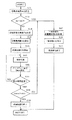
【図5】第1の実施の形態における吸・排気弁の初期化制御を示すフローチャート。
【図6】吸気弁を共振初期化したときの様子を示すタイムチャート。
【図7】吸気弁を一発初期化したときの様子を示すタイムチャート。
【図8】第2の実施の形態における吸・排気弁の初期化制御を示すフローチャート。
【図9】第3の実施の形態における吸・排気弁の初期化制御を示すフローチャート。
【符号の説明】
1 エンジン
2 弁駆動装置
3 吸気弁
4 排気弁
10 クランク角センサ
16 コントロールユニット
33 閉弁用スプリング
42 アーマチャ
43 閉弁用電磁石
44 開弁用電磁石
45 開弁用スプリング[0001]
TECHNICAL FIELD OF THE INVENTION
BACKGROUND OF THE
[0002]
[Prior art]
In this type of electromagnetic valve device, a valve body (intake / exhaust valve) supported at a half-open position is acted on by an electromagnetic force on an armature linked to the valve body by the urging force of a pair of springs. It is a structure that moves from the half-open position to the fully open or fully closed direction, and performs initialization to keep the valve closed or open before starting. Thereafter, when the valve is opened, the energization of the valve closing electromagnet is stopped, the valve body is moved in the valve opening direction by the biasing force of the spring, and the valve opening electromagnet is energized from a position sufficiently close to the valve opening electromagnetic coil. When the valve is closed, energization of the valve-opening electromagnet is stopped and the valve is moved in the valve closing direction by the biasing force of the spring. Open / close control is performed to energize the valve electromagnet to attract and hold the valve electromagnet at the fully closed position.
[0003]
By the way, the method of initialization before the start is simple, in which the valve element in the half-open position is instantaneously attracted to the electromagnet by one energization of the valve-opening electromagnet or the valve-closing electromagnet and initialized. Since the stroke amount (gap) of the valve body is large, the power consumption is large.
[0004]
For this reason, power consumption is achieved by initializing the valve-opening electromagnet and the valve-closing electromagnet alternately, energizing the valve-opening electromagnet, causing a resonance phenomenon by the action of the spring, increasing the amplitude, and then holding the valve closed. A technique for saving power has been proposed (see Japanese Patent Publication No. 4-67005).
[0005]
[Problems to be solved by the invention]
However, in the normal operating temperature range, the power consumption can be reduced by the initialization using the resonance. However, when the initialization is performed at a low temperature, the friction is increased due to the increase in the viscosity of the lubricating oil. In this case, the power consumption is larger than that of the method of initialization, and in some cases, the battery may rise before the completion of the initialization, and the initialization may not be possible.
[0006]
The present invention has been made in view of such a conventional problem, and provides an electromagnetic valve device for an engine which solves the above problem by improving a method of initializing an intake / exhaust valve. Aim.
[0007]
[Means for Solving the Problems]
Therefore, the invention according to
A spring that urges the intake / exhaust valve to the half-open position, a valve-opening electromagnet that attracts the intake / exhaust valve in the valve opening direction and holds the valve open, and a suction valve that attracts and holds the intake / exhaust valve in the valve closing direction A valve closing electromagnet, and an electromagnetic valve control device for the engine, comprising: an initialization means for initializing the intake / exhaust valve by holding the valve open or closed before starting the engine.
Lubricating oil viscosity state determining means for determining the viscous state of the engine lubricating oil;
Based on the determined viscosity state of the engine lubricating oil, when the viscosity of the engine lubricating oil is small, the valve-opening electromagnet and the valve-closing electromagnet are alternately energized to vibrate the intake and exhaust valves to increase the amplitude. The resonance initialization is performed by adsorbing and initializing the valve-opening electromagnet or the valve-closing electromagnet while the viscosity of the engine lubricating oil is large. First initialization method switching means for switching an initialization method so as to perform a one-shot initialization in which an exhaust valve is attracted to a valve opening electromagnet or a valve closing electromagnet and initialized.
If the maximum displacement of the intake / exhaust valve has not reached the set value within a predetermined time after starting the resonance initialization by the first initialization method switching means, a second one for switching to the one-shot initialization. Initialization method switching means;
Is characterized by comprising.
[0008]
According to the first aspect of the invention,
The viscosity state of the engine lubricant is determined by the lubricant viscosity state determination means, and the first initialization switching means alternately energizes the valve opening electromagnet and the valve closing electromagnet when the viscosity of the engine lubrication oil is low. Initialization is performed by resonance initialization in which the suction and exhaust valves vibrate and increase the amplitude while being attracted to the valve-opening electromagnet or valve-closing electromagnet to initialize, and the viscosity of the engine lubricating oil is greatly increased. When the friction of the exhaust valve operation is large, one-shot initialization that attracts and initializes the intake / exhaust valve to the valve-opening electromagnet or the valve-closing electromagnet with one energization of the valve-opening electromagnet or the valve-closing electromagnet , And perform initialization.
[0009]
If the maximum displacement of the intake / exhaust valve does not reach the set value within a predetermined time after the resonance initialization is started, the friction is so large that initialization by resonance initialization is difficult. Is switched to one-shot initialization by the second initialization switching means to perform initialization.
As a result, the initialization method that consumes less power is selected, so that the power consumption can be reduced in any case, and when the friction of the intake / exhaust valve operation is large, the initialization can be reliably performed by one-time initialization. Even if the determination of the viscous state of the engine lubricating oil has a variation or the like and it is difficult to perform initialization by resonance initialization, the initialization can be reliably completed by one-shot initialization. .
[0010]
The invention according to
The lubricating oil viscosity state determining means detects an engine lubricating oil temperature to determine a viscous state of the engine lubricating oil.
[0011]
According to the invention according to
There is a close correlation between the engine lubricating oil temperature and the viscosity state of the engine lubricating oil. When the lubricating oil temperature is low, the viscosity increases. Therefore, the viscous state of the engine lubricating oil is determined by detecting the engine lubricating oil temperature.
[0012]
Thereby, the viscous state of the engine lubricating oil can be determined with high accuracy.
The invention according to
The lubricating oil viscosity state determination means detects the engine cooling water temperature to determine the viscous state of the engine lubricating oil.
[0013]
According to the invention according to
Since the engine cooling water temperature and the engine lubricating oil temperature have a positive correlation, the engine cooling water temperature is detected to estimate the engine lubricating oil temperature, and further, the viscosity state of the engine lubricating oil is estimated. judge.
[0014]
Thereby, the viscosity state of the engine lubricating oil can be determined simply and at low cost by using the water temperature sensor generally mounted for engine control.
The invention according to
The lubricating oil viscosity state determining means detects the engine lubricating oil pressure to determine the viscous state of the engine lubricating oil.
[0015]
According to the invention of
There is a correlation between the engine lubricating oil pressure and the viscosity state of the engine lubricating oil. When the lubricating oil pressure is high, the viscosity increases. Therefore, the viscous state of the engine lubricating oil is determined by detecting the engine lubricating oil pressure.
[0016]
Thereby, the viscous state of the engine lubricating oil can be accurately determined .
[0019]
BEST MODE FOR CARRYING OUT THE INVENTION
Hereinafter, embodiments of the present invention will be described with reference to the drawings.
In FIG. 2 showing a system configuration according to an embodiment of the present invention, an
The detection signals from the various sensors are output to a
[0020]
Here, the hardware of the electromagnetic valve device including the
In FIG. 3, the
[0021]
When the
[0022]
The
[0023]
As shown in FIG. 4, when both the valve-closing
[0024]
Further, as shown in FIGS. 3 and 4, a
Although the opening and closing operation of the
[0025]
Before starting, initialization is performed to hold the
Hereinafter, each embodiment of the initialization control of the intake and exhaust valves will be described. FIG. 5 shows a flow of the first embodiment.
[0026]
In
In
[0027]
If it is determined in
In
[0028]
In
In
Then, when the maximum displacement H max of the
[0029]
FIG. 6 shows the energization control and the displacement of the armature 42 (and the valve body associated therewith) when the resonance initialization is performed on the
On the other hand, if it is determined in
[0030]
In
[0031]
In
In
[0032]
The function of performing the switching determination between the resonance initialization and the one-shot initialization in accordance with the lubricating oil temperature indicating the viscous state of the engine lubricating oil in
[0033]
FIG. 7 shows the energization control and the displacement of the armature 42 (and the valve body associated therewith) when the one-shot initialization is performed on the
In this way, the initialization is normally performed by resonance initialization. However, when the viscosity of the engine lubricating oil becomes too large at the time of cold, the initialization is switched to the one-shot initialization so that the oil is always consumed. Since the initialization method that requires less power is selected, power consumption can be reduced as much as possible, and even if initialization is difficult with resonance initialization, initialization must be performed by one-shot initialization. Can be.
[0034]
On the other hand, when the maximum displacement H max of the
In the first embodiment, the viscous state of the engine lubricating oil is detected and detected by detecting the lubricating oil temperature that is closely correlated with the viscous state, so that the initialization switching determination can be performed with high accuracy.
[0035]
On the other hand, by detecting the engine cooling water temperature having a positive correlation with the engine lubricating oil temperature, it is possible to detect the viscosity state of the engine lubricating oil by estimation, and it is better to detect the lubricating oil temperature in accuracy, Since the detection value of the
[0036]
FIG. 8 shows a flow of a second embodiment for performing initialization control using the engine cooling water temperature detected by the
[0037]
Further, the engine lubricating oil pressure also has a correlation with the viscous state of the engine lubricating oil, and when the lubricating oil pressure is high, the viscosity increases. Therefore, by detecting the engine lubricating oil pressure, the viscous state of the engine lubricating oil is also determined. Can be detected. The detection accuracy of the lubricating oil viscosity state is expected to be intermediate between the case where the lubricating oil temperature is detected and the case where the cooling water temperature is detected. , Which is advantageous when a hydraulic pressure sensor is provided.
[0038]
According to a third embodiment in which the initialization is switched by detecting the viscous state of the engine lubricating oil by detecting the engine lubricating oil pressure, the engine lubricating oil pressure is detected as shown by a dashed line in FIG. A
[0039]
In
[Brief description of the drawings]
FIG. 1 is a block diagram showing the configuration and functions of the present invention.
FIG. 2 is a system configuration diagram of an engine according to the embodiment.
FIG. 3 is a cross-sectional view showing the configuration of the electromagnetic valve device according to the embodiment when the intake and exhaust valves are closed.
FIG. 4 is a cross-sectional view showing a configuration of the electromagnetic valve device when the intake valve is in a half-open state;
FIG. 5 is a flowchart illustrating initialization control of intake and exhaust valves according to the first embodiment.
FIG. 6 is a time chart showing a state when the resonance of the intake valve is initialized.
FIG. 7 is a time chart showing a state when the intake valve is initialized by one shot.
FIG. 8 is a flowchart illustrating initialization control of intake / exhaust valves according to the second embodiment.
FIG. 9 is a flowchart illustrating initialization control of intake / exhaust valves according to the third embodiment.
[Explanation of symbols]
DESCRIPTION OF
10 Crank angle sensor
16 Control unit
33 Valve closing spring
42 armature
43 Electromagnet for closing valve
44 Valve opening electromagnet
45 Valve opening spring
Claims (4)
エンジン潤滑油の粘性状態を判定する潤滑油粘性状態判定手段と、
前記判定されたエンジン潤滑油の粘性状態に基づいて、エンジン潤滑油の粘性が小さいときには、前記開弁用電磁石及び閉弁用電磁石を交互に通電して吸・排気弁を振動させ振幅を増大させつつ開弁用電磁石又は閉弁用電磁石に吸着して初期化する共振初期化を行ない、エンジン潤滑油の粘性が大きいときには、前記開弁用電磁石又は閉弁用電磁石の1回の通電で吸・排気弁を開弁用電磁石又は閉弁用電磁石に吸着して初期化する一発初期化を行なうように、初期化の方式を切り換える第1の初期化方式切換手段と、
前記第1の初期化方式切換手段により前記共振初期化を開始後、所定時間以内に吸・排気弁の最大変位が設定値に達しなかった場合には、前記一発初期化に切り換える第2の初期化方式切換手段と、
を含んで構成したことを特徴とするエンジンの電磁動弁制御装置。A spring that urges the intake / exhaust valve to the half-open position, a valve-opening electromagnet that attracts the intake / exhaust valve in the valve opening direction and holds the valve open, and a valve that holds the intake / exhaust valve in the valve closing direction and holds the valve closed A valve closing electromagnet, and an electromagnetic valve control device for an engine, comprising: an initialization means for initializing the intake / exhaust valve by holding the valve open or closed before starting the engine.
Lubricating oil viscosity state determining means for determining the viscosity state of the engine lubricating oil;
Based on the determined viscosity state of the engine lubricating oil, when the viscosity of the engine lubricating oil is small, the valve-opening electromagnet and the valve-closing electromagnet are alternately energized to vibrate the intake and exhaust valves to increase the amplitude. The resonance initialization is performed by attracting and initializing to the valve-opening electromagnet or the valve-closing electromagnet while the viscosity of the engine lubricating oil is large. First initialization mode switching means for switching an initialization mode so as to perform a one-shot initialization in which the exhaust valve is attracted to the valve opening electromagnet or the valve closing electromagnet and initialized.
If the maximum displacement of the intake / exhaust valve has not reached the set value within a predetermined time after starting the resonance initialization by the first initialization method switching means, the second initialization is switched to the one-shot initialization. Initialization method switching means;
An electromagnetic valve control device for an engine, comprising:
Priority Applications (4)
| Application Number | Priority Date | Filing Date | Title |
|---|---|---|---|
| JP22614799A JP3565100B2 (en) | 1999-08-10 | 1999-08-10 | Engine electromagnetic valve control device |
| EP00116793A EP1076163B1 (en) | 1999-08-10 | 2000-08-03 | Method and apparatus for controlling an electromagnetically operated engine valve to initial condition before engine startup |
| DE60027825T DE60027825T2 (en) | 1999-08-10 | 2000-08-03 | Method and apparatus for controlling an electromagnetically actuated engine valve in response to the initial boundary conditions before engine start |
| US09/635,685 US6374783B1 (en) | 1999-08-10 | 2000-08-10 | Method and apparatus for controlling an electromagnetically operated engine valve to initial condition before engine startup |
Applications Claiming Priority (1)
| Application Number | Priority Date | Filing Date | Title |
|---|---|---|---|
| JP22614799A JP3565100B2 (en) | 1999-08-10 | 1999-08-10 | Engine electromagnetic valve control device |
Publications (2)
| Publication Number | Publication Date |
|---|---|
| JP2001050066A JP2001050066A (en) | 2001-02-23 |
| JP3565100B2 true JP3565100B2 (en) | 2004-09-15 |
Family
ID=16840605
Family Applications (1)
| Application Number | Title | Priority Date | Filing Date |
|---|---|---|---|
| JP22614799A Expired - Fee Related JP3565100B2 (en) | 1999-08-10 | 1999-08-10 | Engine electromagnetic valve control device |
Country Status (4)
| Country | Link |
|---|---|
| US (1) | US6374783B1 (en) |
| EP (1) | EP1076163B1 (en) |
| JP (1) | JP3565100B2 (en) |
| DE (1) | DE60027825T2 (en) |
Families Citing this family (42)
| Publication number | Priority date | Publication date | Assignee | Title |
|---|---|---|---|---|
| US6553966B2 (en) * | 2000-03-14 | 2003-04-29 | Caterpillar Inc | Method of presetting an internal combustion engine |
| JP2001336431A (en) * | 2000-05-29 | 2001-12-07 | Toyota Motor Corp | Internal combustion engine having an electromagnetically driven valve |
| DE10106156A1 (en) * | 2001-02-10 | 2002-09-26 | Bayerische Motoren Werke Ag | Method for starting an internal combustion engine with electromagnetic valve drives |
| ITBO20010389A1 (en) * | 2001-06-19 | 2002-12-19 | Magneti Marelli Spa | METHOD OF CONTROL OF AN ELECTROMAGNETIC ACTUATOR FOR THE CONTROL OF A VALVE OF A MOTOR STARTING FROM A REST CONDITION |
| US6799552B2 (en) * | 2002-09-20 | 2004-10-05 | Caterpillar Inc | System and method for controlling engine operation |
| US6976459B2 (en) * | 2003-07-15 | 2005-12-20 | Caterpillar Inc | Control system and method for a valve actuator |
| JP3842768B2 (en) * | 2003-08-26 | 2006-11-08 | 株式会社東芝 | Service search apparatus and service search method |
| US7509931B2 (en) * | 2004-03-18 | 2009-03-31 | Ford Global Technologies, Llc | Power electronics circuit for electromechanical valve actuator of an internal combustion engine |
| US7128687B2 (en) * | 2004-03-19 | 2006-10-31 | Ford Global Technologies, Llc | Electromechanically actuated valve control for an internal combustion engine |
| US7383820B2 (en) * | 2004-03-19 | 2008-06-10 | Ford Global Technologies, Llc | Electromechanical valve timing during a start |
| US7140355B2 (en) * | 2004-03-19 | 2006-11-28 | Ford Global Technologies, Llc | Valve control to reduce modal frequencies that may cause vibration |
| US7031821B2 (en) * | 2004-03-19 | 2006-04-18 | Ford Global Technologies, Llc | Electromagnetic valve control in an internal combustion engine with an asymmetric exhaust system design |
| US7555896B2 (en) * | 2004-03-19 | 2009-07-07 | Ford Global Technologies, Llc | Cylinder deactivation for an internal combustion engine |
| US7079935B2 (en) * | 2004-03-19 | 2006-07-18 | Ford Global Technologies, Llc | Valve control for an engine with electromechanically actuated valves |
| US7194993B2 (en) * | 2004-03-19 | 2007-03-27 | Ford Global Technologies, Llc | Starting an engine with valves that may be deactivated |
| US7107946B2 (en) | 2004-03-19 | 2006-09-19 | Ford Global Technologies, Llc | Electromechanically actuated valve control for an internal combustion engine |
| US6938598B1 (en) | 2004-03-19 | 2005-09-06 | Ford Global Technologies, Llc | Starting an engine with electromechanical valves |
| US7165391B2 (en) | 2004-03-19 | 2007-01-23 | Ford Global Technologies, Llc | Method to reduce engine emissions for an engine capable of multi-stroke operation and having a catalyst |
| US7559309B2 (en) * | 2004-03-19 | 2009-07-14 | Ford Global Technologies, Llc | Method to start electromechanical valves on an internal combustion engine |
| US7055483B2 (en) | 2004-03-19 | 2006-06-06 | Ford Global Technologies, Llc | Quick starting engine with electromechanical valves |
| US7072758B2 (en) * | 2004-03-19 | 2006-07-04 | Ford Global Technologies, Llc | Method of torque control for an engine with valves that may be deactivated |
| US7032545B2 (en) * | 2004-03-19 | 2006-04-25 | Ford Global Technologies, Llc | Multi-stroke cylinder operation in an internal combustion engine |
| US7128043B2 (en) | 2004-03-19 | 2006-10-31 | Ford Global Technologies, Llc | Electromechanically actuated valve control based on a vehicle electrical system |
| US7107947B2 (en) * | 2004-03-19 | 2006-09-19 | Ford Global Technologies, Llc | Multi-stroke cylinder operation in an internal combustion engine |
| US7032581B2 (en) * | 2004-03-19 | 2006-04-25 | Ford Global Technologies, Llc | Engine air-fuel control for an engine with valves that may be deactivated |
| US7066121B2 (en) * | 2004-03-19 | 2006-06-27 | Ford Global Technologies, Llc | Cylinder and valve mode control for an engine with valves that may be deactivated |
| US7240663B2 (en) * | 2004-03-19 | 2007-07-10 | Ford Global Technologies, Llc | Internal combustion engine shut-down for engine having adjustable valves |
| US7017539B2 (en) * | 2004-03-19 | 2006-03-28 | Ford Global Technologies Llc | Engine breathing in an engine with mechanical and electromechanical valves |
| US7021289B2 (en) * | 2004-03-19 | 2006-04-04 | Ford Global Technology, Llc | Reducing engine emissions on an engine with electromechanical valves |
| US7063062B2 (en) * | 2004-03-19 | 2006-06-20 | Ford Global Technologies, Llc | Valve selection for an engine operating in a multi-stroke cylinder mode |
| US7028650B2 (en) * | 2004-03-19 | 2006-04-18 | Ford Global Technologies, Llc | Electromechanical valve operating conditions by control method |
| US7426911B2 (en) * | 2004-06-21 | 2008-09-23 | Ford Global Technologies, Llc | Enhanced permanent magnet electromagnetic actuator for an electronic valve actuation system of an engine |
| US7021255B2 (en) * | 2004-06-21 | 2006-04-04 | Ford Global Technologies, Llc | Initialization of electromechanical valve actuator in an internal combustion engine |
| US7036469B2 (en) * | 2004-06-21 | 2006-05-02 | Ford Global Technologies, Llc | Bi-directional power electronics circuit for electromechanical valve actuator of an internal combustion engine |
| US7216630B2 (en) * | 2004-10-21 | 2007-05-15 | Siemens Diesel Systems Technology | System and method to control spool stroke motion |
| JP4631860B2 (en) * | 2007-02-19 | 2011-02-16 | トヨタ自動車株式会社 | Multi-fuel internal combustion engine |
| US8316823B2 (en) * | 2008-01-08 | 2012-11-27 | Ngk Spark Plug Co., Ltd. | Plasma jet ignition plug ignition control |
| WO2011133164A1 (en) * | 2010-04-23 | 2011-10-27 | International Engine Intellectual Property Company, Llc | Engine with engine oil viscosity control and method for controlling the same |
| DE102012206419B4 (en) * | 2012-04-19 | 2021-08-12 | Magna Pt B.V. & Co. Kg | Control for a pressure regulating valve |
| US9359963B2 (en) * | 2012-09-20 | 2016-06-07 | Ford Global Technologies, Llc | Gaseous fuel rail depressurization during inactive injector conditions |
| US9341129B2 (en) * | 2013-10-15 | 2016-05-17 | Ford Global Technologies, Llc | Viscosity detection using starter motor |
| US20230127691A1 (en) * | 2021-10-21 | 2023-04-27 | Kenneth Schulz | Electronic Valve Train Assembly |
Family Cites Families (9)
| Publication number | Priority date | Publication date | Assignee | Title |
|---|---|---|---|---|
| DE3307070C2 (en) | 1983-03-01 | 1985-11-28 | FEV Forschungsgesellschaft für Energietechnik und Verbrennungsmotoren mbH, 5100 Aachen | Setting device for a switching element that can be adjusted between two end positions |
| DE3307683C1 (en) * | 1983-03-04 | 1984-07-26 | Klöckner, Wolfgang, Dr., 8033 Krailling | Method for activating an electromagnetic actuator and device for carrying out the method |
| DE19526285A1 (en) * | 1995-07-19 | 1997-01-23 | Schaeffler Waelzlager Kg | Device for lubricant supply of valve gear of internal combustion engine |
| US5645019A (en) | 1996-11-12 | 1997-07-08 | Ford Global Technologies, Inc. | Electromechanically actuated valve with soft landing and consistent seating force |
| US5730091A (en) | 1996-11-12 | 1998-03-24 | Ford Global Technologies, Inc. | Soft landing electromechanically actuated engine valve |
| DE19736137C1 (en) * | 1997-08-20 | 1998-10-01 | Daimler Benz Ag | Starting procedure for IC engine equipped with solenoid- controlled inlet and outlet valves |
| JPH11226147A (en) | 1998-02-12 | 1999-08-24 | Nishi Sports:Kk | Safety device for pole vault |
| JP3414282B2 (en) | 1998-11-13 | 2003-06-09 | 日産自動車株式会社 | Valve train for internal combustion engine |
| DE19922971A1 (en) * | 1999-05-19 | 2000-11-23 | Fev Motorentech Gmbh | Method for starting up an electromagnetic actuator for actuating a gas exchange valve on a piston internal combustion engine |
-
1999
- 1999-08-10 JP JP22614799A patent/JP3565100B2/en not_active Expired - Fee Related
-
2000
- 2000-08-03 DE DE60027825T patent/DE60027825T2/en not_active Expired - Lifetime
- 2000-08-03 EP EP00116793A patent/EP1076163B1/en not_active Expired - Lifetime
- 2000-08-10 US US09/635,685 patent/US6374783B1/en not_active Expired - Lifetime
Also Published As
| Publication number | Publication date |
|---|---|
| JP2001050066A (en) | 2001-02-23 |
| DE60027825D1 (en) | 2006-06-14 |
| EP1076163B1 (en) | 2006-05-10 |
| EP1076163A2 (en) | 2001-02-14 |
| DE60027825T2 (en) | 2006-10-26 |
| US6374783B1 (en) | 2002-04-23 |
| EP1076163A3 (en) | 2002-01-30 |
Similar Documents
| Publication | Publication Date | Title |
|---|---|---|
| JP3565100B2 (en) | Engine electromagnetic valve control device | |
| US5775278A (en) | Energization control method, and electromagnetic control system in electromagnetic driving device | |
| EP1077313B1 (en) | Apparatus for controlling electromagnetically powered engine valve | |
| JP3684966B2 (en) | Engine electromagnetic valve control device | |
| KR100417541B1 (en) | Control Device For Solenoid Driving Valve | |
| JPH02181008A (en) | Electromagnetic valve | |
| JP2001207876A (en) | Engine electromagnetic valve control device | |
| JP3881094B2 (en) | Solenoid valve drive | |
| EP1264969A2 (en) | Apparatus and method for detecting change of neutral position of valve of electromagnetic valve actuation system, and apparatus and method for controlling the valve | |
| JP3820960B2 (en) | Energization control method with step-out detection of electromagnetically driven valve | |
| JPH09320841A (en) | Electromagnetic actuator controller | |
| JP3614092B2 (en) | Valve clearance estimation device and control device for electromagnetically driven valve | |
| JP3601365B2 (en) | Engine electromagnetic valve control device | |
| JP3877851B2 (en) | Solenoid valve drive | |
| JP2010506084A (en) | Electromagnetically driven valve with energy consumption monitor and control method thereof | |
| JP3946361B2 (en) | Control device for electromagnetically driven valve for internal combustion engine | |
| JPH07335437A (en) | Energization control method in electromagnetic drive device | |
| JP3799946B2 (en) | Engine electromagnetic valve control device | |
| JP3649059B2 (en) | Control device for electromagnetically driven exhaust valve | |
| JP2000097057A (en) | Control device for electromagnetically driven valve for internal combustion engine | |
| JP2002238288A (en) | Fault sensor for displacement sensor | |
| JP3603612B2 (en) | Engine intake air amount detection device | |
| JP4259291B2 (en) | Control device for internal combustion engine | |
| JP3684964B2 (en) | Engine intake air amount control device | |
| JP2000073834A (en) | Electromagnetic valve device for internal combustion engine |
Legal Events
| Date | Code | Title | Description |
|---|---|---|---|
| A977 | Report on retrieval |
Free format text: JAPANESE INTERMEDIATE CODE: A971007 Effective date: 20040205 |
|
| A131 | Notification of reasons for refusal |
Free format text: JAPANESE INTERMEDIATE CODE: A131 Effective date: 20040224 |
|
| A521 | Request for written amendment filed |
Free format text: JAPANESE INTERMEDIATE CODE: A523 Effective date: 20040419 |
|
| TRDD | Decision of grant or rejection written | ||
| A01 | Written decision to grant a patent or to grant a registration (utility model) |
Free format text: JAPANESE INTERMEDIATE CODE: A01 Effective date: 20040518 |
|
| A61 | First payment of annual fees (during grant procedure) |
Free format text: JAPANESE INTERMEDIATE CODE: A61 Effective date: 20040531 |
|
| R150 | Certificate of patent or registration of utility model |
Free format text: JAPANESE INTERMEDIATE CODE: R150 |
|
| FPAY | Renewal fee payment (event date is renewal date of database) |
Free format text: PAYMENT UNTIL: 20080618 Year of fee payment: 4 |
|
| FPAY | Renewal fee payment (event date is renewal date of database) |
Free format text: PAYMENT UNTIL: 20090618 Year of fee payment: 5 |
|
| FPAY | Renewal fee payment (event date is renewal date of database) |
Free format text: PAYMENT UNTIL: 20090618 Year of fee payment: 5 |
|
| FPAY | Renewal fee payment (event date is renewal date of database) |
Free format text: PAYMENT UNTIL: 20100618 Year of fee payment: 6 |
|
| FPAY | Renewal fee payment (event date is renewal date of database) |
Free format text: PAYMENT UNTIL: 20110618 Year of fee payment: 7 |
|
| FPAY | Renewal fee payment (event date is renewal date of database) |
Free format text: PAYMENT UNTIL: 20120618 Year of fee payment: 8 |
|
| FPAY | Renewal fee payment (event date is renewal date of database) |
Free format text: PAYMENT UNTIL: 20120618 Year of fee payment: 8 |
|
| FPAY | Renewal fee payment (event date is renewal date of database) |
Free format text: PAYMENT UNTIL: 20130618 Year of fee payment: 9 |
|
| LAPS | Cancellation because of no payment of annual fees |