JP3551034B2 - Car navigation system - Google Patents
Car navigation system Download PDFInfo
- Publication number
- JP3551034B2 JP3551034B2 JP24465298A JP24465298A JP3551034B2 JP 3551034 B2 JP3551034 B2 JP 3551034B2 JP 24465298 A JP24465298 A JP 24465298A JP 24465298 A JP24465298 A JP 24465298A JP 3551034 B2 JP3551034 B2 JP 3551034B2
- Authority
- JP
- Japan
- Prior art keywords
- switch
- state
- navigation
- driver
- turned
- Prior art date
- Legal status (The legal status is an assumption and is not a legal conclusion. Google has not performed a legal analysis and makes no representation as to the accuracy of the status listed.)
- Expired - Fee Related
Links
Images


Landscapes
- Navigation (AREA)
Description
【0001】
【発明の属する技術分野】
本発明は車載ナビゲーション装置、特に走行中の運転者による目的地設定等のナビゲーション操作を禁止する機能を備えた車載ナビゲーション装置に関する。
【0002】
【従来の技術】
従来より、走行中の安全性を確保すべく、走行中は運転者による目的地設定等のナビゲーション操作を禁止する機能を備えた車載ナビゲーション装置が知られている。しかしながら、一律に走行中の操作を禁止してしまうと、運転者のみならず車両の運転に直接関与しない同乗者(助手席者)もナビゲーション操作することができず、目的地を設定する際にはその都度車両を停止させなければならない煩雑さがあった。
【0003】
そこで、従来より走行中であっても同乗者がナビゲーション操作できるように禁止機能を解除するナビゲーション装置が提案されている。例えば、特開平9−292261号公報には、ステアリングに圧力を感知する2個のセンサを設け、運転者がステアリングを握ってこれら2個のセンサがともにオンしている条件下でのみナビゲーション操作を許容する装置が記載されている。これによれば、2個のセンサにより運転者がステアリングを両手で握っていてナビゲーション操作できないことが分かるので、この条件下でナビゲーション操作を許可すれば走行中での同乗者による目的地設定等が可能となる。
【0004】
【発明が解決しようとする課題】
しかしながら、単に2個のセンサがオンされている間にナビゲーション操作を許容する構成では、例えばセンサ故障により常時2個の圧力センサがともにオンしてしまった場合、あるいは車両運転者が故意に圧力センサを常時オンさせる(例えば、粘着テープ等により圧力センサを常にオン状態に維持してしまう)場合、走行中であっても車両運転者によるナビゲーション操作を許容してしまう問題があった。
【0005】
本発明は上記従来技術の有する課題に鑑みなされたものであり、その目的は、ステアリングに設けられたセンサやスイッチの故障、あるいは故意のオン操作(すなわち通常のステアリング操作以外の原因によるオン操作)によるナビゲーション操作禁止機能の誤解除を防止し、より確実に同乗者によるナビゲーション操作を許容する車載ナビゲーション装置を提供することにある。
【0006】
【課題を解決するための手段】
上記目的を達成するために、本発明は、運転者によるナビゲーション操作を禁止する禁止機能を備える車載ナビゲーション装置であって、運転者がステアリングを握った状態で操作可能な操作手段と、前記操作手段が、オフ状態、第1のオン状態、オフ状態、第2のオン状態へと順次操作された場合に前記禁止機能を解除する制御手段とを有することを特徴とする。
【0007】
ここで、前記第1のオン状態は前記操作手段の短押し操作によるものであり、前記第2のオン状態は前記操作手段の長押し操作によるものとすることができる。また、前記第1のオン状態と前記第2のオン状態は、前記操作手段の短押しあるいは長押し操作によるものとすることができる。
【0008】
また、本発明は、運転者によるナビゲーション操作を禁止する禁止機能を備える車載ナビゲーション装置であって、運転者がステアリングを握った状態で操作可能な複数の操作手段と、前記操作手段がともにオフ状態から所定の時間差内においてともにオン状態とされ、さらに前記オン状態から所定時間内に少なくともいずれかの操作手段がオフ状態へと順次操作された場合に前記禁止機能を解除する制御手段とを有することを特徴とする。
【0009】
また、本発明は、運転者によるナビゲーション操作を禁止する禁止機能を備える車載ナビゲーション装置であって、運転者がステアリングを握った状態で操作可能な複数の操作手段と、前記操作手段がともにオフ状態から所定の時間差内においてともにオン状態とされ、さらに前記オン状態から所定走行距離内に少なくともいずれかの操作手段がオフ状態へと順次操作された場合に前記禁止機能を解除する制御手段とを有することを特徴とする。
【0010】
【発明の実施の形態】
以下、図面に基づき本発明の実施形態について説明する。
【0011】
<第1実施形態>
図1には本実施形態の構成ブロック図が示されている。ステアリング10のコラム部(右ハンドル車の場合にはステアリングの左側コラム部)には操作手段としての音声操作トリガ用プッシュスイッチ12が設けられている。スイッチ12はマルチメディアECU(電子制御装置)14に接続されており、スイッチ12からのオンオフ信号はマルチメディアECU14に供給される。一方、ナビゲーションの機能を制御するディスプレイECU16が設けられており、ディスプレイECU16からの制御信号、すなわち操作者がディスプレイのタッチスイッチを操作することで出力される操作制御信号はマルチメディアECU14に供給される。ディスプレイECU16の操作機能には公知のナビゲーション操作機能が含まれ、例えば目的地を設定する、地図画面をスクロールする、地図の縮尺を変更する、経路探索を実行する等がある。また、マルチメディアECU14は、いわゆるナビゲーション機能のみならず、車両外部の情報センタとの情報の送受あるいは車載電話を利用したインターネット機能を制御するECUであり、本実施形態においてはスイッチ12の操作パターンに応じてディスプレイECU16からの制御信号を許可するか禁止するかの判定を行い、走行中におけるナビゲーション操作を制御する制御手段として機能する。マルチメディアECU14及びディスプレイECU16はともにマイクロコンピュータで構成することができる。
【0012】
スイッチ12は基本的には音声操作トリガ用のプッシュスイッチであり、ステアリング10のコラムに後付けされるスイッチである。このスイッチ12を短押し操作するとマルチメディアECU14は車両運転者による音声操作を許可する。このモードにおいては、車両運転者からの音声を認識して指示されたナビゲーション操作を実行する。一方、車両運転者がスイッチ12を短押し操作した後、更に長押し操作した場合には、マルチメディアECU14はディスプレイECU16からの制御信号、すなわち同乗者によるナビゲーション手動操作を許可し、ナビゲーション機能を実行する。
【0013】
図2には、スイッチ12を短押し操作した後に長押し操作する場合のタイミングチャートが示されている。図において、(a)は、スイッチ12のオンオフタイミングであり、(b)はマルチメディアECU14がディスプレイECU16からの信号を許可し同乗者によるナビゲーション操作を許容するタイミングが示されている。時間t1の間、車両運転者がスイッチ12をオン操作し、その後スイッチ12を放して時間t2の間オフ状態とする。その後、再びスイッチ12をオン操作し、時間t3の間スイッチ12を押し続ける。このように短押し操作の後に長押し操作を行い、かつ次のオン操作の継続時間が所定時間t0以上継続している(長押し操作)場合には、マルチメディアECU14はスイッチ12が長押しされている期間だけディスプレイECU16からの信号を許可し、ナビゲーション操作を許容する。
【0014】
このように、単にスイッチ12を操作した場合に同乗者によるナビゲーション操作を許容するのではなく、所定の操作パターン、すなわち短押し操作の後の長押し操作という操作パターンが行われた場合にのみ同乗者によるナビゲーション操作を許容することで、スイッチ12の故障あるいは通常のステアリング操作以外の原因によるオン作動(例えば粘着テープによるスイッチ12の固定)があってもナビゲーション操作が許容されず禁止状態のままとなり、走行中の車両運転者によるナビゲーション操作を禁止して車両走行の一層の安全性が確保できる。
【0015】
なお、ディスプレイ操作部(ディスプレイECU16)は通常運転席と助手席の間のインストルメントパネルに設けられており、右ハンドル者の場合に車両運転者が左手でスイッチ12を操作(短押し及び長押し)しながら同時に右手でディスプレイ操作部を操作することは極めて困難であると考えられる(これにより走行中の運転者による操作が禁止される)。
【0016】
図3には、本実施形態におけるマルチメディアECU14の処理フローチャートが示されている。なお、図において時間t0、t1、t2、t3は図2に示されたタイミングチャートにおける時間と同一であり、αは定数である。図において、マルチメディアECU14はまずスイッチ12の押し時間(オン時間)t1と所定の基準時間t0を比較する(S101)。所定の基準時間t0は例えば2秒に設定することができ、適宜調整可能である。押し時間t1が基準時間t0より短く、短押し操作と判定された場合には、次にオフ状態の時間t2とα・t0を比較する(S102)。オフ時間t2がα・t0より長い場合(2回のオン操作の時間間隔が長い場合の他、短押し操作1回のみの場合も含む)には、マルチメディアECU14は音声操作許可モードに移行する(S106)。
【0017】
一方、オフ時間t2がα・t0より短い場合には、次の押し時間(オン時間)t3と所定の基準時間t0を比較する(S103)。そして、押し時間t3が所定の基準時間t0より長く、長押し操作と判定された場合には、上述したようにマルチメディアECU14はディスプレイ操作許可モードに移行し、ディスプレイECU16からの制御信号を許可して同乗者によるナビゲーション操作を許可する(S104)。許可時間は、長押し操作している時間である。押し時間t3が所定の基準時間t0に達しない場合、すなわち短押しが2回行われた場合には、マルチメディアECU14は同乗者によるナビゲーション操作を許可することなく、単に音声操作許可モードに移行する(S106)。
【0018】
また、第1回目の押し時間t1が所定の基準時間t0を超えた場合、すなわち短押しではなく長押し操作である場合には、マルチメディアECU14は音声操作をキャンセルする(S107)。この状態では、車両運転者による音声は認識されず、ナビゲーション操作は音声、ディスプレイ操作のいずれにおいても禁止される。従って、スイッチ12の故障によるオン状態や故意のオン状態(粘着テープ等による固定オン状態)では、ナビゲーション操作は一律に禁止されることになる。
【0019】
なお、本実施形態においては所定の操作パターンとして短押し操作の後の長押し操作を用いているが、例えば短押し操作を連続して2回操作した場合に走行中の手動ナビゲーション操作を許可することも可能であり、あるいは長押し操作2回の場合に手動ナビゲーション操作を許容することも可能である。要は、スイッチ12が故障等により常にオン状態とされているパターンと異なるパターンを所定パターンに採用し、この所定パターン以外のオン操作ではナビゲーション操作を禁止すればよい。
【0020】
また、本実施形態では音声操作トリガ用スイッチを用いているが、ステアリング近傍に設けられた他のスイッチ、例えば車載電話のフックスイッチを用いて構成することも可能である。
【0021】
<第2実施形態>
図4には、本実施形態における構成ブロック図が示されている。ステアリングには左側スイッチ20及び右側スイッチ22の2個のスイッチが設けられている。なお、これらのスイッチの形態及び配置は従来技術と同様でよい。例えば、スポーツモードとかマニュアルモードと呼ばれるような、ある特定の変速モードを運転者が選んだ際に、ステアリングを握ったまま運転者の変速指示により変速を可能とするスイッチを流用するものが挙げられる。このスイッチは、一般的にモーメンタリスイッチで、1回の操作でアップシフトあるいはダウンシフトを実行するもので、ステアリングの正面(運転者側)、背面(インストルメントパネル側を向く面)あるいは両面に設けられている。図6はこのスイッチの配置を示す一例であり、ダウンシフトスイッチである−のスイッチが正面に設けられ、アップシフトスイッチである+のスイッチが背面(図では便宜上異なる位置に示されているが、実際は−のスイッチとほぼ同位置に設けられる)に設けられ、マニュアルモード選択時に+のスイッチを操作するとアップシフトが実行され、−のスイッチを操作するとダウンシフトが実行されるように構成されている。
【0022】
左側スイッチ20及び右側スイッチ22からのオンオフ信号は操作許可制御手段24に供給される。イグニッションスイッチ(I/Gスイッチ)26からのイグニッションオンオフ信号も操作許可制御手段24に供給される。
【0023】
また、ナビゲーション機能部として車速パルス発生器28、ディスプレイ30、ナビ操作部32及びナビECU34が設けられており、ナビ操作部32からの操作信号に基づきナビECUが所定のナビゲーション機能、すなわち目的地設定、経路探索、ディスプレイ30上への地図データ及び推奨経路の表示等の各種機能を実行する。そして、車速パルス発生器28からの信号に基づき、車両が走行中であると判定された場合にはナビ操作部32からの操作を禁止する。
【0024】
さらに、本実施形態においてはナビECU34のナビゲーション操作禁止機能は操作許可制御手段24からの制御信号に基づいても制御される。すなわち、操作許可制御手段24から操作許可信号が出力された場合にはナビECU34は走行中であってもナビ操作部32からの操作を許容する。操作許可制御手段24は、具体的にはマイクロコンピュータで構成されるECU(電子制御装置)であり、本実施形態で制御手段として機能する。
【0025】
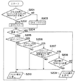
図5には、操作許可制御手段24の処理フローチャートが示されている。まず、I/Gスイッチ26からの信号に基づきイグニッションがオンされたか否かを検出し、イグニッションがオンされた時にステアリング左側スイッチ20及び右側スイッチ22がともにオフ状態となっているか否かを判定する(S201)。この処理は、左側スイッチ20及び右側スイッチ22が故障しているか否か、これらのスイッチが通常のステアリング操作以外の操作により故意にオン状態とされているか否か(粘着テープ等によりオン状態に固定)を判定するためのものである。そして、イグニッションオン時にステアリング左側スイッチ20及び右側スイッチ22がともにオフ状態となっている場合には、これらのスイッチが正常に機能しているとして許可フラグとして1をセットする(S202)。イグニッションをオンする場合、通常はステアリングを握らないか、あるいはステアリングを軽く握る程度なのでスイッチ20、22はオンせず(ステアリングを軽く握った程度ではオンされないよう圧力スイッチの動作圧力を調整すればよい)、イグニッションオン時にオフであれば正常に機能すると考えられるからである。一方、イグニッションオン時に左側スイッチ20あるいは右側スイッチ22のいずれか、あるいは両方ともオン状態とされている場合には、故障状態あるいは何らかの異常状態が生じていると判定し、許可フラグを0にセットする(S203)。なお、許可フラグが0にセットされるとは、後述するように車両走行中におけるナビゲーション操作を一律に禁止することを意味する。
【0026】
以上のようにしてイグニッションオン時に許可フラグをセットした後、車速パルス発生器28からの車速信号に基づき車速が0であるか否か、すなわち車両が走行しているか否かを判定する(S204)。車速が0でない、すなわち走行している場合には、次に許可フラグが1にセットされているか否かを判定する(S205)。許可フラグが1にセットされていない、すなわち0にセットされている場合には、操作許可制御手段24はナビECU34に対して許可信号を出力せず、ナビECU34は操作許可制御手段からの信号に従ってナビ操作部32によるナビゲーション操作を禁止する(S210)。
【0027】
一方、許可フラグが1にセットされている場合には、次にステアリング左側スイッチ20及び右側スイッチ22がともにオン状態とされたか否かを判定する(S206)。車両運転者が両手でステアリングを握っている場合には左側スイッチ20及び右側スイッチ22はオン状態となり、車両運転者が片手のみでステアリングを握っている場合にはいずれかのスイッチのみがオン状態となる。したがって、S206にてNO、すなわち車両運転者が両手でステアリングを握っていない場合には、許可フラグが0にセットされている場合と同様、操作許可制御手段24はナビECU34に対して許可信号は出力せず、ナビ操作部32によるナビゲーション操作を禁止して運転者によるナビゲーション操作を禁止する。一方、ステアリング左側スイッチ20及び右側スイッチ22がともにオンされた場合には、さらに両スイッチがオン状態とされた時間差が所定時間T1秒以内か否かを判定する(S207)。この判定は、車両運転者が左側スイッチ20及び右側スイッチ22を略同時に操作したか否か、すなわち車両運転者が略同時に両手でステアリングを握ったか否かを判定するための処理であり、両スイッチの時間差が所定時間T1秒以内でない場合には、走行中におけるナビゲーション操作を禁止する(S210)。この処理は、例えば車両運転者がイグニッションオン後に粘着テープ等により左側スイッチ20をオン状態に固定し、右側スイッチ22は右手でオン状態にし、運転者が右手のみでステアリングを操作しながらナビゲーション操作を行うことを禁止するためのものである。
【0028】
これに対し、許可フラグが1にセットされ、左側スイッチ20及び右側スイッチ22がともにオン状態とされ、左側スイッチ20及び右側スイッチ22が略同時にオンされた場合には、さらに両スイッチのオン状態が所定時間T2秒以上連続しているか否かを判定する(S208)。この判定は、例えば車両運転者がイグニッションオン後に粘着テープ等により左側スイッチ20及び右側スイッチ22をともにオン状態に固定(あるいは一方のスイッチを片手でオンし、残りのスイッチを粘着テープ等でオン状態に固定)した場合を排除するためであり、所定時間T2秒以上連続してオン状態とされている場合には、走行中におけるナビゲーション操作を禁止する(S210)。両スイッチのオン状態がT2秒以上連続していない場合(スイッチ20、22が正常に機能するのであれば、カーブ路等でステアリング操作のため一時的にオフとなる)、左側スイッチ20及び右側スイッチ22がともにオン状態となっている間に限りナビ操作部32によるナビゲーション操作を許可する(S209)。なお、同乗者が目的地等を入力するためにナビゲーション操作に要する時間は1〜2分程度であると考えられるので、基準時間T2としては、例えば120秒とすることができる。もちろん、基準時間T2の値は60秒、90秒など適宜設定することが可能である。
【0029】
なお、運転者が両手でステアリングを操作しているか否かを判断するためには、図5のS206のみに基づく判定で十分であるが、より正確な検出を行うためには、S206とS207の組み合わせ、あるいはS206、S207、S208の組み合わせを用いるとよい。
【0030】
このように、本実施形態においては所定の操作パターンとしてステアリングに2個設けられたスイッチが略同時に操作された場合とし、イグニッションオン時という通常のステアリング操作では2個のスイッチを同時にオンすることはない状況下でオンされていないこと、及び所定時間以上継続して両スイッチがオン状態とされていないことを条件に走行中であってもナビゲーション操作を禁止する機能を解除するものであり、走行中における車両運転者によるナビゲーション操作を確実に禁止しつつ同乗者による操作を可能として安全性を一層向上させることができる。
【0031】
なお、本実施形態においてはイグニッションオン時に両スイッチがオン状態とされていないことで両スイッチが故障ではなく故意にオン状態に固定されていないことを確認しているが、本発明はこれに限定されることなく他の方法で確認することもできる。例えば、運転者がサイドブレーキを操作した時に両スイッチがオフ状態か否かを判定することによっても確認することができる。要は、通常のステアリング操作では両スイッチがオンされることがない状況下でオンされているか否かを確認し、通常のステアリング操作時以外で両スイッチがオンされている場合にはナビゲーション操作の禁止状態を維持すればよい。
【0032】
また、本実施形態では、所定時間T2以上両スイッチがオンされている場合には、イグニッションオン後のある時点で両スイッチが故障したか、あるいは故意にオン状態に固定されたとしてナビゲーション操作を禁止しているが、所定時間ではなく所定走行距離以上にわたって両スイッチがオン状態となっているか否かを判定してもよい。時間、距離のいずれで判定するかは任意であり、均等である。
【0033】
【発明の効果】
以上説明したように、本発明によれば走行中の車両運転者によるナビゲーション操作を確実に防止し、かつ同乗者によるナビゲーション操作を可能としてナビゲーションシステムの使い勝手及び信頼性を高めることが可能となる。
【図面の簡単な説明】
【図1】本発明の実施形態の構成ブロック図である。
【図2】本発明の実施形態のタイミングチャートである。
【図3】本発明の実施形態の処理フローチャートである。
【図4】本発明の他の実施形態の構成ブロック図である。
【図5】本発明の他の実施形態の処理フローチャートである。
【図6】本発明の他の実施形態のスイッチ配置説明図である。
【符号の説明】
10 ステアリング、12 スイッチ、14 マルチメディアECU、16 ディスプレイECU、20 ステアリング左側スイッチ、22 ステアリング右側スイッチ、24 操作許可制御手段、32 ナビ操作部、34 ナビECU。[0001]
TECHNICAL FIELD OF THE INVENTION
The present invention relates to an in-vehicle navigation device, and more particularly to an in-vehicle navigation device having a function of prohibiting a traveling driver from performing navigation operations such as setting a destination.
[0002]
[Prior art]
2. Description of the Related Art Conventionally, there has been known an in-vehicle navigation device having a function of prohibiting a driver from performing a navigation operation such as setting a destination while traveling in order to ensure safety during traveling. However, if the operation during traveling is uniformly prohibited, not only the driver but also the passenger (passenger passenger) who is not directly involved in driving the vehicle cannot perform the navigation operation, and when setting the destination, Had to stop the vehicle each time.
[0003]
Therefore, conventionally, a navigation device has been proposed in which a prohibition function is released so that a passenger can perform a navigation operation even while traveling. For example, in Japanese Patent Application Laid-Open No. 9-292261, two sensors for sensing pressure are provided on a steering wheel, and a driver operates the steering wheel to perform a navigation operation only under a condition in which both the two sensors are on. Acceptable devices are described. According to this, the two sensors indicate that the driver can hold the steering wheel with both hands and cannot perform navigation operation. Therefore, if the navigation operation is permitted under these conditions, the destination setting by the fellow passengers while traveling is possible. It becomes possible.
[0004]
[Problems to be solved by the invention]
However, in a configuration in which the navigation operation is simply permitted while the two sensors are turned on, for example, when the two pressure sensors are always turned on due to a sensor failure, or the vehicle driver intentionally operates the pressure sensor. (For example, the pressure sensor is always kept on by an adhesive tape or the like), there is a problem that the navigation operation by the vehicle driver is allowed even during traveling.
[0005]
The present invention has been made in view of the above-mentioned problems of the related art, and has as its object the failure of a sensor or a switch provided in a steering or the intentional on operation (that is, the on operation due to a cause other than a normal steering operation). It is an object of the present invention to provide an in-vehicle navigation device that prevents a navigation operation prohibition function from being erroneously released by a driver and allows a passenger to more reliably perform a navigation operation.
[0006]
[Means for Solving the Problems]
In order to achieve the above object, the present invention provides an in-vehicle navigation device having a prohibition function for prohibiting a navigation operation by a driver, comprising: an operation means operable while the driver holds a steering wheel; Is characterized by having control means for canceling the prohibition function when sequentially operated from an off state, a first on state, an off state, and a second on state .
[0007]
Here, the first ON state may be based on a short press operation of the operation unit, and the second ON state may be based on a long press operation of the operation unit. Further, the first ON state and the second ON state can be caused by a short push or a long push operation of the operation means.
[0008]
Further, the present invention is an in-vehicle navigation device having a prohibition function for prohibiting a navigation operation by a driver, wherein a plurality of operation means that can be operated while the driver is holding the steering wheel, and the operation means are both in an off state And control means for canceling the prohibition function when at least one of the operation means is sequentially operated from the on state to the off state within a predetermined time from the on state. It is characterized by.
[0009]
Further, the present invention is an in-vehicle navigation device having a prohibition function for prohibiting a navigation operation by a driver, wherein a plurality of operation means that can be operated while the driver is holding the steering wheel, and the operation means are both in an off state And control means for releasing the prohibition function when at least one of the operation means is sequentially operated from the on state to the off state within a predetermined travel distance from the on state within a predetermined time difference from the on state. It is characterized by the following.
[0010]
BEST MODE FOR CARRYING OUT THE INVENTION
Hereinafter, embodiments of the present invention will be described with reference to the drawings.
[0011]
<First embodiment>
FIG. 1 shows a configuration block diagram of the present embodiment. A push switch 12 for triggering voice operation is provided on a column portion of the steering 10 (a left column portion of the steering in the case of a right-hand drive vehicle). The switch 12 is connected to a multimedia ECU (electronic control device) 14, and an on / off signal from the switch 12 is supplied to the
[0012]
The switch 12 is basically a push switch for triggering a voice operation, and is a switch attached to a column of the steering wheel 10. When the switch 12 is pressed for a short time, the
[0013]
FIG. 2 shows a timing chart when the switch 12 is short-pressed and then long-pressed. In the figure, (a) shows the on / off timing of the switch 12, and (b) shows the timing at which the
[0014]
In this way, the navigation operation by the fellow passenger is not permitted when the switch 12 is simply operated, but only when the predetermined operation pattern, that is, the operation pattern of the long press operation after the short press operation, is performed. By allowing the navigation operation by the user, the navigation operation is not allowed and remains in the prohibited state even if the switch 12 is turned on (for example, the switch 12 is fixed with an adhesive tape) due to a failure of the switch 12 or a cause other than the normal steering operation. Further, the navigation operation by the vehicle driver during traveling is prohibited, so that further safety of the vehicle traveling can be ensured.
[0015]
The display operation unit (display ECU 16) is normally provided on the instrument panel between the driver's seat and the passenger's seat. In the case of a right-hand drive, the vehicle driver operates the switch 12 with the left hand (short press and long press). It is considered that it is extremely difficult to operate the display operation unit with the right hand at the same time (the operation by the driver while traveling is prohibited).
[0016]
FIG. 3 shows a processing flowchart of the
[0017]
On the other hand, if the off time t2 is shorter than α · t0, the next pressing time (on time) t3 is compared with a predetermined reference time t0 (S103). When the pressing time t3 is longer than the predetermined reference time t0 and it is determined that the operation is the long pressing operation, the
[0018]
If the first press time t1 exceeds a predetermined reference time t0, that is, if the press operation is not a short press but a long press, the
[0019]
In this embodiment, a long-press operation after a short-press operation is used as a predetermined operation pattern. For example, when the short-press operation is performed twice consecutively, a manual navigation operation during traveling is permitted. It is also possible to allow a manual navigation operation in the case of two long press operations. In short, a pattern different from the pattern in which the switch 12 is always on due to a failure or the like may be adopted as the predetermined pattern, and the navigation operation may be prohibited in an on operation other than the predetermined pattern.
[0020]
In this embodiment, the voice operation trigger switch is used. However, it is also possible to use another switch provided near the steering wheel, for example, a hook switch of a vehicle-mounted telephone.
[0021]
<Second embodiment>
FIG. 4 shows a configuration block diagram in the present embodiment. The steering is provided with two switches, a left switch 20 and a right switch 22. Note that the form and arrangement of these switches may be the same as in the related art. For example, when a driver selects a specific shift mode such as a sports mode or a manual mode, a switch that enables a shift by a driver's shift instruction while holding the steering wheel is used. . This switch is generally a momentary switch that performs an upshift or downshift with a single operation, and is provided on the front (driver side), back (side facing the instrument panel side) or both sides of the steering. Have been. FIG. 6 shows an example of the arrangement of the switches, in which a-switch, which is a downshift switch, is provided on the front, and a + switch, which is an upshift switch, is shown on the back (in FIG. (In actuality, the switch is provided at substantially the same position as the-switch.) When the + switch is operated during manual mode selection, an upshift is executed, and when the-switch is operated, a downshift is executed. .
[0022]
On / off signals from the left switch 20 and the right switch 22 are supplied to the operation
[0023]
Further, a vehicle
[0024]
Further, in the present embodiment, the navigation operation prohibition function of the
[0025]
FIG. 5 shows a processing flowchart of the operation permission control means 24. First, it is detected whether or not the ignition is turned on based on a signal from the I /
[0026]
After the permission flag is set when the ignition is turned on as described above, it is determined whether or not the vehicle speed is 0, that is, whether or not the vehicle is running, based on the vehicle speed signal from the vehicle speed pulse generator 28 (S204). . If the vehicle speed is not 0, that is, if the vehicle is traveling, it is determined whether or not the permission flag is set to 1 (S205). If the permission flag is not set to 1, that is, set to 0, the operation permission control means 24 does not output a permission signal to the
[0027]
On the other hand, if the permission flag is set to 1, it is determined whether both the left steering switch 20 and the right switch 22 are turned on (S206). When the vehicle driver is holding the steering wheel with both hands, the left switch 20 and the right switch 22 are turned on. When the vehicle driver is holding the steering wheel with only one hand, only one of the switches is turned on. Become. Therefore, if NO in S206, that is, if the vehicle driver is not holding the steering wheel with both hands, the operation permission control means 24 sends a permission signal to the
[0028]
On the other hand, when the permission flag is set to 1, the left switch 20 and the right switch 22 are both turned on, and when the left switch 20 and the right switch 22 are turned on substantially simultaneously, both the switches are further turned on. It is determined whether or not the predetermined time T2 seconds or more is continuous (S208). This determination is made, for example, by the vehicle driver fixing both the left switch 20 and the right switch 22 to an on state with an adhesive tape or the like after the ignition is turned on (or turning on one switch with one hand and turning on the other switch with an adhesive tape or the like). In this case, the navigation operation during running is prohibited (S210). If the ON state of both switches is not continuous for more than T2 seconds (if the switches 20 and 22 function normally, they are temporarily turned off for steering operation on a curved road or the like), the left switch 20 and the right switch The navigation operation by the
[0029]
In order to determine whether or not the driver is operating the steering wheel with both hands, the determination based on only S206 in FIG. 5 is sufficient. However, in order to perform more accurate detection, the determination in S206 and S207 is performed. It is preferable to use a combination or a combination of S206, S207, and S208.
[0030]
As described above, in the present embodiment, it is assumed that two switches provided on the steering wheel are operated substantially simultaneously as a predetermined operation pattern, and it is not possible to simultaneously turn on the two switches in a normal steering operation when the ignition is turned on. The function to prohibit navigation operation even if the vehicle is running on the condition that it has not been turned on in the absence of any condition and that both switches have not been turned on continuously for a predetermined time or more. It is possible to further improve the safety by enabling the operation by the fellow passenger while reliably prohibiting the navigation operation by the vehicle driver in the middle.
[0031]
In the present embodiment, it is confirmed that both switches are not turned on when the ignition is turned on, so that both switches are not malfunctioning and are not intentionally fixed to the on state, but the present invention is not limited to this. It can also be confirmed in other ways without being done. For example, it can also be confirmed by determining whether or not both switches are off when the driver operates the side brake. In short, it is checked whether both switches are turned on under the condition that both switches are not turned on in normal steering operation, and if both switches are turned on other than during normal steering operation, navigation operation The prohibition state may be maintained.
[0032]
Further, in this embodiment, when both switches are on for a predetermined time T2 or more, the navigation operation is prohibited assuming that both switches have failed at some point after the ignition is turned on or are intentionally fixed to the on state. However, it may be determined whether or not both switches are on for a predetermined traveling distance or more, not for a predetermined time. The determination based on time or distance is arbitrary and equal.
[0033]
【The invention's effect】
As described above, according to the present invention, it is possible to reliably prevent the navigation operation by the vehicle driver while traveling, and to enable the navigation operation by the fellow passenger, thereby improving the usability and reliability of the navigation system.
[Brief description of the drawings]
FIG. 1 is a configuration block diagram of an embodiment of the present invention.
FIG. 2 is a timing chart of the embodiment of the present invention.
FIG. 3 is a processing flowchart according to the embodiment of the present invention.
FIG. 4 is a configuration block diagram of another embodiment of the present invention.
FIG. 5 is a processing flowchart of another embodiment of the present invention.
FIG. 6 is an explanatory diagram of a switch arrangement according to another embodiment of the present invention.
[Explanation of symbols]
Reference Signs List 10 steering, 12 switches, 14 multimedia ECU, 16 display ECU, 20 steering left switch, 22 steering right switch, 24 operation permission control means, 32 navigation operation unit, 34 navigation ECU.
Claims (5)
運転者がステアリングを握った状態で操作可能な操作手段と、
前記操作手段が、オフ状態、第1のオン状態、オフ状態、第2のオン状態へと順次操作された場合に前記禁止機能を解除する制御手段と、
を有することを特徴とする車載ナビゲーション装置。An in-vehicle navigation device having a prohibition function for prohibiting a navigation operation by a driver,
Operating means that can be operated while the driver holds the steering wheel,
Control means for canceling the prohibition function when the operation means is sequentially operated to an off state, a first on state, an off state, a second on state ;
An on-vehicle navigation device comprising:
前記第1のオン状態は前記操作手段の短押し操作によるものであり、前記第2のオン状態は前記操作手段の長押し操作によるものであることを特徴とする車載ナビゲーション装置。 The device of claim 1,
The in-vehicle navigation device according to claim 1, wherein the first ON state is based on a short press operation of the operation unit, and the second ON state is based on a long press operation of the operation unit.
前記第1のオン状態と前記第2のオン状態は、前記操作手段の短押しあるいは長押し操作によるものであることを特徴とする車載ナビゲーション装置。 The device of claim 1,
The on- vehicle navigation device is characterized in that the first ON state and the second ON state are caused by a short press or a long press operation of the operation means .
運転者がステアリングを握った状態で操作可能な複数の操作手段と、
前記操作手段がともにオフ状態から所定の時間差内においてともにオン状態とされ、さらに前記オン状態から所定時間内に少なくともいずれかの操作手段がオフ状態へと順次操作された場合に前記禁止機能を解除する制御手段と、
を有することを特徴とする車載ナビゲーション装置。 An in-vehicle navigation device having a prohibition function for prohibiting a navigation operation by a driver,
A plurality of operating means that can be operated while the driver holds the steering wheel;
The prohibition function is released when both of the operation means are turned on within a predetermined time difference from the off state, and at least one of the operation means is sequentially operated to the off state within a predetermined time from the on state. Control means for performing
An on-vehicle navigation device comprising:
運転者がステアリングを握った状態で操作可能な複数の操作手段と、 A plurality of operating means that can be operated while the driver holds the steering wheel,
前記操作手段がともにオフ状態から所定の時間差内においてともにオン状態とされ、さらに前記オン状態から所定走行距離内に少なくともいずれかの操作手段がオフ状態へと順次操作された場合に前記禁止機能を解除する制御手段と、 The prohibition function is activated when both of the operation means are turned on within a predetermined time difference from the off state and at least one of the operation means is sequentially operated from the on state to the off state within a predetermined traveling distance. Control means for canceling,
を有することを特徴とする車載ナビゲーション装置。 An in-vehicle navigation device comprising:
Priority Applications (1)
| Application Number | Priority Date | Filing Date | Title |
|---|---|---|---|
| JP24465298A JP3551034B2 (en) | 1998-08-31 | 1998-08-31 | Car navigation system |
Applications Claiming Priority (1)
| Application Number | Priority Date | Filing Date | Title |
|---|---|---|---|
| JP24465298A JP3551034B2 (en) | 1998-08-31 | 1998-08-31 | Car navigation system |
Publications (2)
| Publication Number | Publication Date |
|---|---|
| JP2000074684A JP2000074684A (en) | 2000-03-14 |
| JP3551034B2 true JP3551034B2 (en) | 2004-08-04 |
Family
ID=17121944
Family Applications (1)
| Application Number | Title | Priority Date | Filing Date |
|---|---|---|---|
| JP24465298A Expired - Fee Related JP3551034B2 (en) | 1998-08-31 | 1998-08-31 | Car navigation system |
Country Status (1)
| Country | Link |
|---|---|
| JP (1) | JP3551034B2 (en) |
Families Citing this family (7)
| Publication number | Priority date | Publication date | Assignee | Title |
|---|---|---|---|---|
| JP4496655B2 (en) * | 2001-02-09 | 2010-07-07 | マツダ株式会社 | Vehicle display device |
| JP5079473B2 (en) * | 2007-11-29 | 2012-11-21 | 株式会社デンソーアイティーラボラトリ | In-vehicle device operation device |
| WO2012098660A1 (en) * | 2011-01-20 | 2012-07-26 | 三菱電機株式会社 | Navigation device and charging control device for electric vehicle |
| JP5566338B2 (en) * | 2011-05-30 | 2014-08-06 | 三菱電機株式会社 | Information input device and navigation device |
| JP2016147667A (en) * | 2016-03-09 | 2016-08-18 | パイオニア株式会社 | INPUT DEVICE, INPUT DEVICE SETTING METHOD, INPUT DEVICE PROGRAM, AND RECORDING MEDIUM |
| JP2018170011A (en) * | 2018-05-17 | 2018-11-01 | パイオニア株式会社 | Input device, setting method for input device, program for input device, and recording medium |
| JP2020144900A (en) * | 2020-05-07 | 2020-09-10 | パイオニア株式会社 | Input device, setting method of input device, program for input device, and recording medium |
-
1998
- 1998-08-31 JP JP24465298A patent/JP3551034B2/en not_active Expired - Fee Related
Also Published As
| Publication number | Publication date |
|---|---|
| JP2000074684A (en) | 2000-03-14 |
Similar Documents
| Publication | Publication Date | Title |
|---|---|---|
| JP3925421B2 (en) | Control device for in-vehicle equipment | |
| KR100282099B1 (en) | Devices with a human-machine interface | |
| JPH08184449A (en) | Control device | |
| JP3551034B2 (en) | Car navigation system | |
| JPH1120608A (en) | Apparatus for identifying the occupancy of the passenger seat of a car | |
| WO2003016110A8 (en) | Method for assisting the user of a piece of equipment in locating a control element | |
| JP3925056B2 (en) | Voice control device for vehicle | |
| JP2004196260A (en) | Display device for vehicles | |
| JP2005178471A (en) | Vehicle display system and control method thereof | |
| JP2005156257A (en) | Input device for vehicle | |
| JP2979753B2 (en) | Switch control device for vehicle | |
| JP2009204354A (en) | Navigation control device | |
| JP2988083B2 (en) | In-vehicle display control device | |
| JPS59130741A (en) | Shift position informting apparatus for vehicle | |
| JP3749161B2 (en) | In-vehicle information equipment input device | |
| JP2004243940A (en) | Driving assistance device and vehicle information presentation device | |
| JP4194006B2 (en) | Electronic equipment control system | |
| JP2562209Y2 (en) | Electric auto change | |
| JP2659625B2 (en) | Starting device for vehicle occupant protection device | |
| JP2004026050A (en) | Display device for vehicles | |
| JP2001174268A (en) | On-vehicle navigation system | |
| JP2008195311A (en) | Vehicle safe traveling device | |
| JP3931697B2 (en) | Abnormality diagnosis device for guidance system | |
| JP5835029B2 (en) | Vehicle display device | |
| JPH10264680A (en) | Constant speed traveling equipment for vehicles |
Legal Events
| Date | Code | Title | Description |
|---|---|---|---|
| TRDD | Decision of grant or rejection written | ||
| A01 | Written decision to grant a patent or to grant a registration (utility model) |
Effective date: 20040330 Free format text: JAPANESE INTERMEDIATE CODE: A01 |
|
| A61 | First payment of annual fees (during grant procedure) |
Effective date: 20040412 Free format text: JAPANESE INTERMEDIATE CODE: A61 |
|
| R150 | Certificate of patent (=grant) or registration of utility model |
Free format text: JAPANESE INTERMEDIATE CODE: R150 |
|
| LAPS | Cancellation because of no payment of annual fees |