JP2025500748A - Contact lenses and related methods - Google Patents
Contact lenses and related methods Download PDFInfo
- Publication number
- JP2025500748A JP2025500748A JP2024529974A JP2024529974A JP2025500748A JP 2025500748 A JP2025500748 A JP 2025500748A JP 2024529974 A JP2024529974 A JP 2024529974A JP 2024529974 A JP2024529974 A JP 2024529974A JP 2025500748 A JP2025500748 A JP 2025500748A
- Authority
- JP
- Japan
- Prior art keywords
- power
- radial
- annular region
- curvature
- lens
- Prior art date
- Legal status (The legal status is an assumption and is not a legal conclusion. Google has not performed a legal analysis and makes no representation as to the accuracy of the status listed.)
- Pending
Links
Images




Classifications
-
- G—PHYSICS
- G02—OPTICS
- G02B—OPTICAL ELEMENTS, SYSTEMS OR APPARATUS
- G02B1/00—Optical elements characterised by the material of which they are made; Optical coatings for optical elements
- G02B1/04—Optical elements characterised by the material of which they are made; Optical coatings for optical elements made of organic materials, e.g. plastics
-
- G—PHYSICS
- G02—OPTICS
- G02C—SPECTACLES; SUNGLASSES OR GOGGLES INSOFAR AS THEY HAVE THE SAME FEATURES AS SPECTACLES; CONTACT LENSES
- G02C7/00—Optical parts
- G02C7/02—Lenses; Lens systems ; Methods of designing lenses
- G02C7/04—Contact lenses for the eyes
- G02C7/041—Contact lenses for the eyes bifocal; multifocal
- G02C7/044—Annular configuration, e.g. pupil tuned
-
- B—PERFORMING OPERATIONS; TRANSPORTING
- B29—WORKING OF PLASTICS; WORKING OF SUBSTANCES IN A PLASTIC STATE IN GENERAL
- B29C—SHAPING OR JOINING OF PLASTICS; SHAPING OF MATERIAL IN A PLASTIC STATE, NOT OTHERWISE PROVIDED FOR; AFTER-TREATMENT OF THE SHAPED PRODUCTS, e.g. REPAIRING
- B29C39/00—Shaping by casting, i.e. introducing the moulding material into a mould or between confining surfaces without significant moulding pressure; Apparatus therefor
- B29C39/02—Shaping by casting, i.e. introducing the moulding material into a mould or between confining surfaces without significant moulding pressure; Apparatus therefor for making articles of definite length, i.e. discrete articles
-
- B—PERFORMING OPERATIONS; TRANSPORTING
- B29—WORKING OF PLASTICS; WORKING OF SUBSTANCES IN A PLASTIC STATE IN GENERAL
- B29D—PRODUCING PARTICULAR ARTICLES FROM PLASTICS OR FROM SUBSTANCES IN A PLASTIC STATE
- B29D11/00—Producing optical elements, e.g. lenses or prisms
- B29D11/00009—Production of simple or compound lenses
- B29D11/00038—Production of contact lenses
-
- B—PERFORMING OPERATIONS; TRANSPORTING
- B29—WORKING OF PLASTICS; WORKING OF SUBSTANCES IN A PLASTIC STATE IN GENERAL
- B29D—PRODUCING PARTICULAR ARTICLES FROM PLASTICS OR FROM SUBSTANCES IN A PLASTIC STATE
- B29D11/00—Producing optical elements, e.g. lenses or prisms
- B29D11/00009—Production of simple or compound lenses
- B29D11/00038—Production of contact lenses
- B29D11/00125—Auxiliary operations, e.g. removing oxygen from the mould, conveying moulds from a storage to the production line in an inert atmosphere
-
- G—PHYSICS
- G02—OPTICS
- G02B—OPTICAL ELEMENTS, SYSTEMS OR APPARATUS
- G02B1/00—Optical elements characterised by the material of which they are made; Optical coatings for optical elements
- G02B1/04—Optical elements characterised by the material of which they are made; Optical coatings for optical elements made of organic materials, e.g. plastics
- G02B1/041—Lenses
- G02B1/043—Contact lenses
-
- G—PHYSICS
- G02—OPTICS
- G02C—SPECTACLES; SUNGLASSES OR GOGGLES INSOFAR AS THEY HAVE THE SAME FEATURES AS SPECTACLES; CONTACT LENSES
- G02C7/00—Optical parts
- G02C7/02—Lenses; Lens systems ; Methods of designing lenses
-
- G—PHYSICS
- G02—OPTICS
- G02C—SPECTACLES; SUNGLASSES OR GOGGLES INSOFAR AS THEY HAVE THE SAME FEATURES AS SPECTACLES; CONTACT LENSES
- G02C7/00—Optical parts
- G02C7/02—Lenses; Lens systems ; Methods of designing lenses
- G02C7/021—Lenses; Lens systems ; Methods of designing lenses with pattern for identification or with cosmetic or therapeutic effects
-
- G—PHYSICS
- G02—OPTICS
- G02C—SPECTACLES; SUNGLASSES OR GOGGLES INSOFAR AS THEY HAVE THE SAME FEATURES AS SPECTACLES; CONTACT LENSES
- G02C7/00—Optical parts
- G02C7/02—Lenses; Lens systems ; Methods of designing lenses
- G02C7/022—Ophthalmic lenses having special refractive features achieved by special materials or material structures
-
- G—PHYSICS
- G02—OPTICS
- G02C—SPECTACLES; SUNGLASSES OR GOGGLES INSOFAR AS THEY HAVE THE SAME FEATURES AS SPECTACLES; CONTACT LENSES
- G02C7/00—Optical parts
- G02C7/02—Lenses; Lens systems ; Methods of designing lenses
- G02C7/04—Contact lenses for the eyes
-
- G—PHYSICS
- G02—OPTICS
- G02C—SPECTACLES; SUNGLASSES OR GOGGLES INSOFAR AS THEY HAVE THE SAME FEATURES AS SPECTACLES; CONTACT LENSES
- G02C7/00—Optical parts
- G02C7/02—Lenses; Lens systems ; Methods of designing lenses
- G02C7/04—Contact lenses for the eyes
- G02C7/048—Means for stabilising the orientation of lenses in the eye
-
- G—PHYSICS
- G02—OPTICS
- G02C—SPECTACLES; SUNGLASSES OR GOGGLES INSOFAR AS THEY HAVE THE SAME FEATURES AS SPECTACLES; CONTACT LENSES
- G02C7/00—Optical parts
- G02C7/02—Lenses; Lens systems ; Methods of designing lenses
- G02C7/04—Contact lenses for the eyes
- G02C7/049—Contact lenses having special fitting or structural features achieved by special materials or material structures
-
- G—PHYSICS
- G02—OPTICS
- G02C—SPECTACLES; SUNGLASSES OR GOGGLES INSOFAR AS THEY HAVE THE SAME FEATURES AS SPECTACLES; CONTACT LENSES
- G02C7/00—Optical parts
- G02C7/02—Lenses; Lens systems ; Methods of designing lenses
- G02C7/06—Lenses; Lens systems ; Methods of designing lenses bifocal; multifocal ; progressive
- G02C7/061—Spectacle lenses with progressively varying focal power
- G02C7/063—Shape of the progressive surface
- G02C7/066—Shape, location or size of the viewing zones
-
- G—PHYSICS
- G02—OPTICS
- G02C—SPECTACLES; SUNGLASSES OR GOGGLES INSOFAR AS THEY HAVE THE SAME FEATURES AS SPECTACLES; CONTACT LENSES
- G02C2202/00—Generic optical aspects applicable to one or more of the subgroups of G02C7/00
- G02C2202/04—Lenses comprising decentered structures
-
- G—PHYSICS
- G02—OPTICS
- G02C—SPECTACLES; SUNGLASSES OR GOGGLES INSOFAR AS THEY HAVE THE SAME FEATURES AS SPECTACLES; CONTACT LENSES
- G02C2202/00—Generic optical aspects applicable to one or more of the subgroups of G02C7/00
- G02C2202/24—Myopia progression prevention
Landscapes
- Physics & Mathematics (AREA)
- Health & Medical Sciences (AREA)
- Ophthalmology & Optometry (AREA)
- General Physics & Mathematics (AREA)
- Optics & Photonics (AREA)
- General Health & Medical Sciences (AREA)
- Engineering & Computer Science (AREA)
- Manufacturing & Machinery (AREA)
- Mechanical Engineering (AREA)
- Eyeglasses (AREA)
- Radiation-Therapy Devices (AREA)
- Lens Barrels (AREA)
- Surface Treatment Of Glass (AREA)
Abstract

コンタクトレンズ(201)、及び、そのようなレンズを製造する方法が、記載される。レンズ(201)は、光学ゾーン(202)を含む。光学ゾーン(202)は、中央領域(205)を含み、当該中央領域(205)は、第1光軸(219)と、ベースの半径方向の曲率屈折力と、ベースの半径方向のサジタル屈折力と、第1光軸上にある曲率中心と、を有する。光学ゾーン(202)は、環状領域(203)を含み、当該環状領域(203)の幅の中間の点において、環状領域(203)はXの半径方向の曲率屈折力を有し、当該Xはベースの半径方向の曲率屈折力よりも大きい。環状領域(203)は、光軸(219)から第1距離である軸外曲率中心を有しており、その幅の中間の点において、環状領域(203)は、Yのサジタル屈折力を有しており、当該Yは、ベースの半径方向のサジタル屈折力よりも大きく、当該Yは前記Xよりも小さい。
A contact lens (201) and a method of manufacturing such a lens are described. The lens (201) includes an optic zone (202). The optic zone (202) includes a central region (205) having a first optical axis (219), a base radial curvature power, a base radial sagittal power, and a center of curvature that lies on the first optical axis. The optic zone (202) includes an annular region (203) having a radial curvature power of X at a point midway through the width of the annular region (203), where X is greater than the radial curvature power of the base. The annular region (203) has an off-axis center of curvature that is a first distance from the optical axis (219), and at a point midway across its width, the annular region (203) has a sagittal power of Y that is greater than the radial sagittal power of the base and that is less than X.
Description
本発明は、コンタクトレンズに関する。本発明は、特に(排他的では無く)、近視の進行を遅らせるためのコンタクトレンズに関する。本発明は、特に(排他的では無く)、老眼者による使用のためのコンタクトレンズに関する。本発明はまた、そのようなレンズを製造する方法に関する。 The present invention relates to contact lenses. The present invention relates particularly (but not exclusively) to contact lenses for slowing the progression of myopia. The present invention relates particularly (but not exclusively) to contact lenses for use by presbyopic individuals. The present invention also relates to a method for making such lenses.
子供と大人とを含む多くの人が、近視(近眼)を矯正するためにコンタクトレンズを必要としており、多くの大人が老眼(加齢に伴う調節能力の低下により近くの物体に焦点を合わせることができない状態)を矯正するためにレンズを必要とし得る。 Many people, both children and adults, need contact lenses to correct myopia (nearsightedness), and many adults may need lenses to correct presbyopia (the inability to focus on nearby objects due to age-related decreased ability to accommodate).
近視の目は、遠くの物体からの入射光を網膜の前方の位置に焦点合わせする。その結果、光は網膜の前方の平面に向かって収束し、網膜に向かって発散し、網膜に到達する時には焦点が外れている。近視を矯正するための従来のレンズ(例えば、眼鏡レンズやコンタクトレンズ)は、遠くの物体からの入射光が目に到達する前に、光の収束を低減し(コンタクトレンズの場合)、または、当該入射光の発散をもたらし(眼鏡の場合)、これにより、焦点の位置が網膜上に移動される。 A myopic eye focuses incident light from distant objects to a location in front of the retina. As a result, the light converges toward the plane in front of the retina and diverges toward the retina, reaching the retina out of focus. Conventional lenses for correcting myopia (e.g., eyeglass lenses and contact lenses) reduce the convergence (in the case of contact lenses) or cause the divergence (in the case of eyeglasses) of incident light from distant objects before it reaches the eye, thereby shifting the location of the focus onto the retina.
老眼の目は、近くの物体に合わせて形を効果的に変えることができない。このため、老眼の人は、近くの物体に焦点を合わせることができない。老眼を矯正するための従来のレンズ(例えば、眼鏡レンズやコンタクトレンズ)は、二重焦点レンズや累進レンズを含み、それらは、近くを見るのに最適化された領域と、遠くを見るのに最適化された領域と、を含む。老眼は、また、二重焦点レンズや多焦点レンズを使用して、あるいは、モノビジョンレンズ(一方の目に遠くを見るレンズが提供され、他方の目に近くを見るレンズが提供される等、それぞれの目に異なる処方が提供される)を使用して、治療され得る。 A presbyopic eye cannot effectively change shape to accommodate nearby objects. Because of this, a person with presbyopia cannot focus on nearby objects. Conventional lenses (e.g., eyeglass lenses and contact lenses) for correcting presbyopia include bifocal or progressive lenses, which include an area optimized for near vision and an area optimized for distance vision. Presbyopia can also be treated using bifocal or multifocal lenses, or using monovision lenses (where each eye is provided with a different prescription, such as one eye being provided with a lens for distance vision and the other eye being provided with a lens for near vision).
数十年前に、子供や若者の近視の進行は、過小矯正、すなわち、焦点を網膜に近づけるが完全に網膜上にまでは近づけない、によって、遅らせたり予防したりできることが提案された。しかしながら、当該アプローチは、必然的に、近視を完全に矯正するレンズで得られる視力と比較して、遠方視力の低下をもたらす。更に、近視の進行を制御するのに過小矯正が有効であるというのは、現在では疑わしいと見なされている。近視を矯正するためのより最近のアプローチは、遠方視力の完全な矯正を提供する1または複数の領域と、過小矯正すなわち意図的に近視性デフォーカスを誘導する1または複数の領域と、の両方を有するレンズを提供することである。当該アプローチは、良好な遠方視力を提供しながら、子供や若者の近視の発症または進行を予防または遅らせることができる、と示唆されている。デフォーカス(焦点ぼけ)を提供する領域を有するレンズの場合、遠方視力の完全な矯正を提供する領域は、通常、ベース屈折力領域と呼ばれ、過小矯正を提供するかまたは意図的に近視性デフォーカスを誘導する領域は、通常、近視性デフォーカス領域または追加屈折力領域と呼ばれる(屈折力が、遠方領域の屈折力(視度)よりも、より正であるか、より少ない負である)。 Decades ago, it was proposed that the progression of myopia in children and adolescents could be slowed or prevented by undercorrection, i.e., by bringing the focal point closer to but not completely on the retina. However, this approach inevitably results in a decrease in distance visual acuity compared to that achieved with a lens that completely corrects myopia. Furthermore, the effectiveness of undercorrection in controlling the progression of myopia is now considered questionable. A more recent approach to correcting myopia is to provide lenses that have both one or more regions that provide complete correction of distance vision and one or more regions that undercorrect, i.e., intentionally induce myopic defocus. It has been suggested that this approach can prevent or slow the onset or progression of myopia in children and adolescents while providing good distance visual acuity. For lenses with regions that provide defocus, the region that provides full correction of distance vision is usually called the base power region, and the region that provides undercorrection or intentionally induces myopic defocus is usually called the myopic defocus region or add power region (where the power is more positive or less negative than the power (diopter) of the distance region).
追加屈折力領域の表面(典型的には前面)は、遠方屈折力領域の曲率半径よりも小さい曲率半径を有し、従って、より正またはより少ない負の屈折力(度数)を目に提供する。追加屈折力領域は、入ってくる平行光(すなわち、遠くからの光)を網膜の前方(すなわち、水晶体により近い)の眼中に集束させるように設計される。遠方屈折力領域は、光を集束させて網膜に像を形成するように設計される(すなわち、水晶体からより通い)。 The surface of the add power region (typically the anterior surface) has a smaller radius of curvature than the distance power region, thus providing more positive or less negative optical power (diopter) to the eye. The add power region is designed to focus incoming parallel light (i.e., light from far away) into the eye in front of the retina (i.e., closer to the lens). The distance power region is designed to focus light to form an image on the retina (i.e., closer to the lens).
近視の進行を低減する公知のタイプのコンタクトレンズは、MISIGHT(CooperVision, Inc.)の名前で入手できる、二重焦点コンタクトレンズである。この二重焦点レンズは、老眼の視力を改善するように構成された二焦点コンタクトレンズや多焦点コンタクトレンズとは異なり、遠くの物体と近くの物体との両方を見るために、遠方矯正(すなわち、ベース屈折力)の使用を提供できる所定の光学的寸法で構成される。追加屈折力を有する二重焦点レンズの治療ゾーンは、遠くと近くの両方の視距離で近視性デフォーカスな像を提供する。 A known type of contact lens that reduces the progression of myopia is the bifocal contact lens available under the name MISIGHT (CooperVision, Inc.). Unlike bifocal or multifocal contact lenses that are designed to improve vision in presbyopia, bifocal lenses are constructed with predetermined optical dimensions that provide the use of distance correction (i.e., base power) to view both distant and near objects. The treatment zone of the bifocal lens, which has an add power, provides myopic defocused images at both distant and near viewing distances.
これらのレンズは、近視の発症または進行を予防または遅らせるのに有益であることが見出されているが、環状の追加屈折力領域は、不所望の視覚的副作用を引き起こし得る。網膜の前方に環状の追加屈折力領域によって集束される光は、焦点から発散して、網膜にデフォーカスされた(焦点がずれた)輪を形成する。従って、これらのレンズの着用者は、特に街灯や車のヘッドライトなどの小さくて明るい物体の場合、網膜上に形成される像の周囲にリングまたは「ハロー」が見える場合がある。また、近くの物体に焦点を合わせるために、目の自然な遠近調節(すなわち、焦点距離を変える目の自然な能力)を使用するのではなく、理論的には、着用者は、近くの物体に焦点を合わせるために、環状の追加屈折力領域から生じる網膜の前方の追加の焦点を利用し得てしまう。これは、換言すれば、着用者が、老視矯正レンズが使用されるのと同じ態様でレンズを無意識に(気付かずに)使用し得ることになり、これは、若い対象者にとって望ましくない。 Although these lenses have been found to be beneficial in preventing or slowing the onset or progression of myopia, the annular additional power region may cause undesirable visual side effects. Light focused by the annular additional power region in front of the retina diverges from the focal point to form a defocused ring on the retina. Thus, wearers of these lenses may see a ring or "halo" around the image formed on the retina, especially for small, bright objects such as street lamps or car headlights. Also, rather than using the eye's natural accommodation (i.e., the eye's natural ability to change focal length) to focus on nearby objects, the wearer could theoretically use the additional focal point in front of the retina resulting from the annular additional power region to focus on nearby objects. This, in turn, means that the wearer may unconsciously use the lens in the same manner that presbyopic corrective lenses are used, which is undesirable for younger subjects.
近視の治療に使用され得て、MISIGHT(CooperVision,Inc.)レンズ及び前述の他の同様のレンズにおいて焦点距離画像の周りに観察されるハローを排除するように設計された、更なるレンズが開発された。当該レンズでは、環状の領域が、軸上画像が網膜の前方に形成されないように構成され、それにより、近くの目標に眼が順応する必要を避けるようにそのような画像が使用されてしまうことを防止する。むしろ、遠方の点光源が、環状の領域によって、近くの追加屈折力焦点面でリング状の焦線に結像され、遠方焦点面の網膜上で、周囲の「ハロー」効果なしに、小さなスポットサイズの光となる。 A further lens has been developed that may be used to treat myopia and is designed to eliminate the halos observed around the focal distance image in the MISIGHT (CooperVision, Inc.) lens and other similar lenses mentioned above. In this lens, an annular region is configured to prevent an on-axis image from being formed in front of the retina, thereby preventing such an image from being used to avoid the need for the eye to accommodate to near targets. Rather, a distant point source is imaged by the annular region into a ring-like focal line at the near add-power focal plane, resulting in a small spot size of light on the retina at the far focal plane without the surrounding "halo" effect.
近視の治療のために、追加的な近視性デフォーカスを導入するレンズを提供することが有益であり得ると認識されている。老眼の治療のために、焦点深度を拡張するレンズを提供することが有益であり得る。 It has been recognized that for the treatment of myopia, it may be beneficial to provide a lens that introduces additional myopic defocus. For the treatment of presbyopia, it may be beneficial to provide a lens that extends the depth of focus.
第1の態様によれば、本開示は、光学ゾーンを含むコンタクトレンズを提供する。光学ゾーンは、中央領域を含み、当該中央領域は、第1光軸と、ベースの半径方向の(ラジアル)曲率屈折力と、ベースの半径方向の(ラジアル)サジタル屈折力と、を有する。中央領域は、第1光軸上にある曲率中心を有する。光学ゾーンは、環状領域を含み、当該環状領域の幅の中間の点において、環状領域は、Xの半径方向の曲率屈折力を有し、当該Xは、ベースの半径方向の曲率屈折力よりも大きい。環状領域は、光軸から第1距離である軸外曲率中心を有している。その幅の中間の点において、環状領域は、Yの半径方向のサジタル屈折力を有しており、当該Yは、ベースの半径方向のサジタル屈折力よりも大きく、当該Yは前記Xよりも小さい。 According to a first aspect, the present disclosure provides a contact lens including an optical zone. The optical zone includes a central region having a first optical axis, a radial curvature power of a base, and a radial sagittal power of a base. The central region has a center of curvature on the first optical axis. The optical zone includes an annular region having a radial curvature power of X at a midpoint of the width of the annular region, where X is greater than the radial curvature power of the base. The annular region has an off-axis center of curvature that is a first distance from the optical axis. At a midpoint of the width of the annular region, the annular region has a radial sagittal power of Y, where Y is greater than the radial sagittal power of the base, where Y is less than X.
第2の態様によれば、本開示は、レンズを製造する方法を提供する。当該方法は、本発明の第1の態様のコンタクトレンズを形成する工程を備える。 According to a second aspect, the present disclosure provides a method of manufacturing a lens, the method comprising forming a contact lens according to the first aspect of the present invention.
もちろん、本開示の一態様に関連して説明される特徴が、本開示の他の態様に組み込まれ得ることが、理解されるであろう。例えば、本開示の方法は、本開示の装置を参照して説明された特徴を組み込み得るし、その逆もまた同様である。 Of course, it will be understood that features described in relation to one aspect of the present disclosure may be incorporated in other aspects of the present disclosure. For example, a method of the present disclosure may incorporate features described with reference to an apparatus of the present disclosure, and vice versa.
ここで、添付の概略図を参照して、例示のみを目的として、本発明の実施形態が説明される。 An embodiment of the present invention will now be described, by way of example only, with reference to the accompanying schematic drawings.
第1の態様によって、本開示は、コンタクトレンズを提供する。当該レンズは、中央領域を含む光学ゾーンを備え、当該中央領域は、第1光軸と、ベースの半径方向の曲率屈折力と、ベースの半径方向のサジタル屈折力と、第1光軸上にある曲率中心と、を有する。光学ゾーンは、環状領域を含む。当該環状領域の幅の中間の点において、環状領域は、Xの半径方向の曲率屈折力を有する。当該Xは、ベースの半径方向の曲率屈折力よりも大きい。環状領域は、光軸から第1距離である軸外曲率中心を有し、その幅の中間の点において、環状領域は、Yの半径方向のサジタル屈折力を有しており、当該Yは、ベースの半径方向のサジタル屈折力よりも大きく、当該Yは前記Xよりも小さい。 According to a first aspect, the present disclosure provides a contact lens. The lens comprises an optical zone including a central region having a first optical axis, a radial curvature power of a base, a radial sagittal power of the base, and a center of curvature on the first optical axis. The optical zone includes an annular region. At a midpoint of the width of the annular region, the annular region has a radial curvature power of X, which is greater than the radial curvature power of the base. The annular region has an off-axis center of curvature that is a first distance from the optical axis, and at a midpoint of the width, the annular region has a radial sagittal power of Y, which is greater than the radial sagittal power of the base and which is less than X.
本明細書で使用される場合、コンタクトレンズという用語は、眼の前面に配置され得る眼科用レンズを指す。そのようなコンタクトレンズは、臨床的に許容可能な眼上の(on-eye)動きを提供し、人の眼に結合しない、ことが理解されるであろう。コンタクトレンズは、角膜レンズ(例えば、眼の角膜上に載るレンズ)の形態であり得る。コンタクトレンズは、ヒドロゲルコンタクトレンズまたはシリコーンヒドロゲルコンタクトレンズなどのソフトコンタクトレンズであり得る。レンズは、近視の発症または進行を予防または遅らせるために使用されるレンズであり得て、また、レンズは、近視の目に拡張された焦点深度を提供するために使用されるものであり得る。 As used herein, the term contact lens refers to an ophthalmic lens that may be placed on the front of the eye. It will be understood that such contact lenses provide clinically acceptable on-eye movement and do not bind to the human eye. The contact lens may be in the form of a corneal lens (e.g., a lens that rests on the cornea of the eye). The contact lens may be a soft contact lens, such as a hydrogel contact lens or a silicone hydrogel contact lens. The lens may be a lens used to prevent or slow the onset or progression of myopia, and the lens may be one used to provide an extended depth of focus to a myopic eye.
本開示によるコンタクトレンズは、光学ゾーンを備える。光学ゾーンは、光学的機能を有するレンズ部分を包含する。光学ゾーンは、使用時に眼の瞳孔上に位置決めされるように構成される。本開示によるコンタクトレンズの場合、光学ゾーンは、中央領域と、中央領域を取り囲む環状領域(単数または複数)と、を含む。光学ゾーンは、周辺ゾーンによって取り囲まれている。周辺ゾーンは、光学ゾーンの一部ではないが、レンズが着用される時に光学ゾーンの外側で虹彩の上方に位置し、例えば、レンズのサイズを増大して当該レンズをより扱いやすくしたり、レンズの回転を防止するためのバラストを提供したり、及び/または、レンズ着用者の快適性を改善する形状領域を提供したり、といった機械的機能を提供する。周辺ゾーンは、コンタクトレンズの縁部まで延在し得る。 A contact lens according to the present disclosure comprises an optical zone. The optical zone encompasses a portion of the lens having an optical function. The optical zone is configured to be positioned over the pupil of the eye in use. In a contact lens according to the present disclosure, the optical zone includes a central region and an annular region or regions surrounding the central region. The optical zone is surrounded by a peripheral zone. The peripheral zone is not part of the optical zone, but is located outside the optical zone and above the iris when the lens is worn, and provides a mechanical function, such as increasing the size of the lens to make it easier to handle, providing ballast to prevent lens rotation, and/or providing a shaped region that improves comfort for the lens wearer. The peripheral zone may extend to the edge of the contact lens.
本開示の一実施形態によるコンタクトレンズは、着用者の眼上に位置決めされる時にレンズを方向付けるためのバラストを含み得る。バラストをコンタクトレンズに組み込んだ本開示の実施形態は、着用者の眼上に配置される時、着用者の瞼の作用で所定の安息角まで回転する。例えば、バラストは楔であり得て、回転は、当該楔上の瞼の作用によって生じ得る。コンタクトレンズを方向付けるためにコンタクトレンズをバラストすることは、当該技術分野で良く知られている。例えば、トーリックコンタクトレンズは、当該レンズによって提供される直交円筒矯正が着用者の眼の乱視に対して正確に整列するように、レンズを方向付けるべくバラストされている。本開示のコンタクトレンズは、所与の向きで着用者に特定の利益を提供し得る。例えば、コンタクトレンズは、最大追加屈折力子午線が特定の方向にある時に、着用者に特定の利益を提供し得る。 A contact lens according to an embodiment of the present disclosure may include a ballast to orient the lens when positioned on the wearer's eye. An embodiment of the present disclosure incorporating a ballast into a contact lens rotates to a predetermined angle of repose under the action of the wearer's eyelid when placed on the wearer's eye. For example, the ballast may be a wedge and the rotation may be caused by the action of the eyelid on the wedge. Ballasting a contact lens to orient the contact lens is well known in the art. For example, a toric contact lens is ballasted to orient the lens such that the orthogonal cylindrical correction provided by the lens is precisely aligned with the astigmatism of the wearer's eye. A contact lens of the present disclosure may provide a particular benefit to a wearer in a given orientation. For example, a contact lens may provide a particular benefit to a wearer when the meridian of maximum addition power is in a particular direction.
コンタクトレンズは、形状が実質的に円形であり得て、約4mm~約20mmの直径を有し得る。光学ゾーンは、形状が実質的に円形であり得て、約2mm~約10mmの直径を有し得る。幾つかの実施形態では、コンタクトレンズは、13mm~15mmの直径を有し、光学ゾーンは、7mm~9mmまでの直径を有する。 The contact lens may be substantially circular in shape and may have a diameter of about 4 mm to about 20 mm. The optical zone may be substantially circular in shape and may have a diameter of about 2 mm to about 10 mm. In some embodiments, the contact lens has a diameter of 13 mm to 15 mm and the optical zone has a diameter of 7 mm to 9 mm.
第1光軸は、レンズの中心線に沿って存在し得る。中央領域は、遠方の点物体からの光を、第1光軸上で、遠位焦点面で第1光軸上のスポットに、焦点合わせ(集束)させ得る。本明細書で使用される場合、面という用語は、物理的な表面を指すのではなく、遠方の物体からの光が焦点合わせされる点を通って描かれ得る面を指す。このような面は、像面(曲面であり得る)またはイメージシェルとも呼ばれる。目は、曲がった網膜上に光を焦点合わせする。完全に焦点が合った目では、イメージシェルの曲率は、網膜の曲率と一致する。従って、目は、光を平坦な数学上の平面には集束させない。そうでありながら、当該技術分野では、網膜の曲面は、一般に(平)面と呼ばれる。 The first optical axis may be along the centerline of the lens. The central region may focus (converge) light from a distant point object on the first optical axis to a spot on the first optical axis at the distal focal plane. As used herein, the term surface does not refer to a physical surface, but rather to a surface that can be drawn through a point where light from a distant object is focused. Such a surface is also called an image surface (which may be curved) or an image shell. The eye focuses light onto a curved retina. In a perfectly focused eye, the curvature of the image shell matches the curvature of the retina. Thus, the eye does not focus light onto a flat mathematical plane. Nevertheless, in the art, the curved surface of the retina is commonly referred to as a (planar) surface.
中央領域は、形状が実質的に円形であり得て、約2mm~約9mm、好ましくは2~7mm、の直径を有し得る。中央領域は、形状が実質的に楕円形であってもよい。環状領域は、中央領域の周縁から半径方向外側に約0.1mm~約4mmの間、好ましくは約0.5mm~約1.5mmの間、延在し得る。例えば、環状領域の半径方向幅は、約0.1mm~約4mm、好ましくは約0.5mm~約1.5mm、であり得る。中央領域の周縁は、中央領域と環状領域との間の境界を定義(画定)し得て、従って、環状領域は中央領域に隣接(adjacent)し得る。 The central region may be substantially circular in shape and may have a diameter of about 2 mm to about 9 mm, preferably 2 to 7 mm. The central region may be substantially elliptical in shape. The annular region may extend radially outward from the periphery of the central region between about 0.1 mm to about 4 mm, preferably between about 0.5 mm to about 1.5 mm. For example, the radial width of the annular region may be between about 0.1 mm to about 4 mm, preferably between about 0.5 mm to about 1.5 mm. The periphery of the central region may define a boundary between the central region and the annular region, such that the annular region is adjacent to the central region.
環状領域は、中央領域に隣接(abut)し得る。ブレンディング(混合)領域が、中央領域と環状領域との間に設けられてもよい。ブレンディング領域は、中央領域及び環状領域によって提供される光学系に実質的に影響を与えるべきではなく、当該ブレンディング領域は、0.05mm以下の半径方向幅を有し得る。もっとも、それは、幾つか実施形態では、0.2mm程度の幅であり得るし、あるいは、0.5mm程度の幅であり得る。 The annular region may be adjacent to the central region. A blending region may be provided between the central region and the annular region. The blending region should not substantially affect the optical system provided by the central region and the annular region, and may have a radial width of 0.05 mm or less, although in some embodiments it may be as wide as 0.2 mm or as wide as 0.5 mm.
本開示の文脈では、レンズの中央領域及び環状領域の屈折力は、半径方向の曲率屈折力、周方向の曲率屈折力、平均の曲率屈折力(半径方向の曲率屈折力と周方向の曲率屈折力との平均である)、半径方向のサジタル屈折力、周方向のサジタル屈折力、及び、平均のサジタル屈折力(半径方向のサジタル屈折力と周方向のサジタル屈折力との平均である)、として定義され得る。 In the context of this disclosure, the refractive powers of the central and annular regions of the lens may be defined as the radial curvature power, the circumferential curvature power, the average curvature power (which is the average of the radial and circumferential curvature powers), the radial sagittal power, the circumferential sagittal power, and the average sagittal power (which is the average of the radial sagittal power and the circumferential sagittal power).
曲率屈折力とサジタル屈折力とは、以下のように定義される。 Curvature power and sagittal power are defined as follows:
ある波面Wの場合、当該波面の中心に垂直な線から半径方向距離r(瞳孔半径)の点において、
W(r) = A*r2
ここで、Aは関数である。
For a given wavefront W, at a point a radial distance r (pupil radius) from a line perpendicular to the center of the wavefront,
W(r) = A* r2
Here, A is a function.
波面曲率、または、曲率屈折力Pcは、波面の二次導関数の関数である。波面スロープ、または、スロープベースの屈折力Psは、波面の一次導関数の関数であって、波面のスロープ(勾配)によって変化する。 The wavefront curvature, or curvature power Pc, is a function of the second derivative of the wavefront. The wavefront slope, or slope-based power Ps, is a function of the first derivative of the wavefront and varies with the slope of the wavefront.
単純な球面レンズの場合、曲率屈折力Pcは、以下のように定義される。
スロープベースの屈折力Psは、以下のように定義される。
すなわち、近軸(パラキシャル)を仮定した単純なレンズの場合、Pc=Psである。
For a simple spherical lens, the curvature power Pc is defined as follows:
The slope-based power Ps is defined as follows:
That is, in the case of a simple lens assumed to be paraxial (paraaxial), Pc=Ps.
半径方向の曲率屈折力とは、レンズの曲率中心から半径方向外側に延びる方向での曲率屈折力である。周方向の曲率屈折力とは、レンズの周に沿って延びる、一定の半径座標における、曲率屈折力である。平均の曲率屈折力は、半径方向の曲率屈折力と周方向の曲率屈折力との平均を提供する。 Radial curvature power is the curvature power in a direction extending radially outward from the center of curvature of the lens. Circumferential curvature power is the curvature power at a constant radial coordinate extending around the circumference of the lens. The average curvature power provides the average of the radial and circumferential curvature powers.
半径方向のサジタル屈折力とは、レンズの中心から半径方向外側に延びる方向でのサジタル屈折力である。周方向のサジタル屈折力とは、レンズの周に沿って延びる、一定の半径座標における、サジタル屈折力である。 Radial sagittal power is the sagittal power in a direction extending radially outward from the center of the lens. Circumferential sagittal power is the sagittal power at a constant radial coordinate extending along the circumference of the lens.
中央領域は、サジタル屈折力と同一の曲率屈折力を有し得る。これが、ここでは、ベース曲率屈折力、ベースサジタル屈折力、または、ベース屈折力、と称される。中央領域の公称屈折力は、コンタクトレンズのパッケージ上に提供されるようなコンタクトレンズのラベル付けされた屈折力(度数)に対応するであろう(もっとも、実践上は、同一の値を有しない場合もある)。これは、中央領域(の全体)に亘って測定される平均サジタル屈折力または平均曲率屈折力であろう。中央領域の測定される屈折力は、中央領域(の全体)に亘って直接的に測定される平均曲率屈折力または平均サジタル屈折力である。これは、公称屈折力とは異なり得る。 The central region may have a curvature power that is the same as the sagittal power. This is referred to herein as the base curvature power, base sagittal power, or base power. The nominal power of the central region would correspond to the labeled power (power) of the contact lens as provided on the contact lens packaging (although in practice they may not have the same value). This would be the average sagittal power or the average curvature power measured over (the entirety of) the central region. The measured power of the central region is the average curvature power or the average sagittal power measured directly over (the entirety of) the central region. This may differ from the nominal power.
近視の治療に使用されるレンズの場合、ベース屈折力は、負であるか、あるいは、ゼロの近傍であって、中央領域が遠方視力を矯正する。ベース屈折力は、0.5ディオプトリ(D)と-15.0ディオプトリとの間であり得る。ベース屈折力は、-0.25D~-15.0Dであり得る。 For lenses used to treat myopia, the base power is negative or near zero, with the central region correcting distance vision. The base power can be between 0.5 diopters (D) and -15.0 diopters. The base power can be -0.25D to -15.0D.
中央領域のベース屈折力は、レンズの表面の曲率から帰結し得る。当該ベース屈折力は、レンズの前面の曲率、及び/または、レンズの後面の曲率、から帰結し得る。 The base power of the central region may result from the curvature of the lens surface. The base power may result from the curvature of the front surface of the lens and/or the curvature of the rear surface of the lens.
本開示の文脈において、環状領域は、光学ゾーンを取り囲む実質的に環状の領域である。それは、実質的に円形、または、実質的に楕円形、を有し得る。それは、光学ゾーンを完全に取り囲み得る。それは、光学ゾーンを部分的に取り囲み得る。 In the context of this disclosure, an annular region is a substantially annular region that surrounds the optical zone. It may have a substantially circular or substantially elliptical shape. It may completely surround the optical zone. It may partially surround the optical zone.
本開示の実施形態では、環状領域の半径方向の曲率屈折力は、中央領域のベースの半径方向の曲率屈折力よりも大きい。 In an embodiment of the present disclosure, the radial curvature refractive power of the annular region is greater than the radial curvature refractive power of the base of the central region.
環状領域の半径方向の曲率曲率力は、当該環状領域の少なくとも1つの表面の曲率によって決定され得る。環状領域の半径方向の曲率屈折力は、レンズの前面及び/または後面の曲率から帰結し得る。環状領域は、中央領域よりも、大きい曲率、すなわち、小さい曲率半径、を有し得る。環状領域の前面が、中央領域の曲率よりも大きい曲率、すなわち、小さい曲率半径、を有し得る。代替的または追加的に、環状領域の後面が、中央領域の曲率よりも大きい曲率を有し得る。 The radial curvature power of the annular region may be determined by the curvature of at least one surface of the annular region. The radial curvature power of the annular region may result from the curvature of the anterior and/or posterior surfaces of the lens. The annular region may have a larger curvature, i.e., a smaller radius of curvature, than the central region. The annular region's anterior surface may have a larger curvature, i.e., a smaller radius of curvature, than the central region. Alternatively or additionally, the annular region's posterior surface may have a larger curvature than the central region.
半径方向の曲率屈折力は、環状領域に亘って変化し得る。環状領域の幅の中間の点において、環状領域の半径方向の曲率屈折力は、Xである。半径方向の曲率屈折力は、ベースの半径方向の曲率屈折力よりも、より正の屈折力(またはより負の屈折力)であろう。環状領域の正味の半径方向の曲率屈折力は、中央領域のベースの半径方向の曲率屈折力と、環状領域の半径方向の曲率追加屈折力と、の合計である。例えば、ベースの半径方向の曲率屈折力が-3.0Dであって、環状領域の半径方向の曲率追加屈折力が+4.0Dである場合、環状領域の正味の半径方向の曲率屈折力は+1.0Dである。 The radial curvature power may vary across the annular region. At a point midway across the width of the annular region, the radial curvature power of the annular region is X. The radial curvature power may be more positive (or more negative) than the radial curvature power of the base. The net radial curvature power of the annular region is the sum of the radial curvature power of the base of the central region and the radial curvature add power of the annular region. For example, if the radial curvature power of the base is -3.0D and the radial curvature add power of the annular region is +4.0D, then the net radial curvature power of the annular region is +1.0D.
Xの値は、+0.5D~+20.0Dの間であり得る。Xの値は、ベースの半径方向の曲率屈折力より、+10.0D大きくてよい(すなわち、環状領域の幅の中間の点における半径方向の曲率追加屈折力が、+10.0Dであり得る)。Xの値は、ベースの半径方向の曲率屈折力より、+11.0D大きくてよい(すなわち、環状領域の幅の中間の点における半径方向の曲率追加屈折力が、+11.0Dであり得る)。Xの値は、ベースの半径方向の曲率屈折力より、+12.0D大きくてよい(すなわち、環状領域の幅の中間の点における半径方向の曲率追加屈折力が、+12.0Dであり得る)。 The value of X can be between +0.5D and +20.0D. The value of X can be +10.0D greater than the radial curvature power of the base (i.e., the radial curvature add power at the midpoint of the width of the annular region can be +10.0D). The value of X can be +11.0D greater than the radial curvature power of the base (i.e., the radial curvature add power at the midpoint of the width of the annular region can be +11.0D). The value of X can be +12.0D greater than the radial curvature power of the base (i.e., the radial curvature add power at the midpoint of the width of the annular region can be +12.0D).
環状領域は中央領域に対して傾斜されている、と理解され得る。本明細書で使用される場合、環状領域の傾斜とは、横方向の傾斜ではなく、円対称の傾斜を意味する。環状領域は、レンズの周に沿って延びる曲線回りに傾斜されており、環状領域の外側縁が第1方向に移動し、環状領域の内側縁が反対方向に移動している。環状領域の傾斜は、環状領域の半径方向のサジタル屈折力を変化させるであろう。なぜなら、これは、波面の1次導関数の関数であるからである。もっとも、それは、環状領域の半径方向の曲率屈折力は変化させないであろう。なぜなら、これは、波面の2次導関数の関数だからである。環状領域を中央領域に対して傾けることは、環状領域の曲率中心が中央領域の第1光軸から第1距離だけシフトされることを意味する。環状領域の半径方向のサジタル屈折力は、本開示の実施形態では、環状領域の幅に亘って変化し得る。環状領域の幅の中間の点において、環状領域の半径方向のサジタル屈折力は、Yである。Yは、中央領域のベースの半径方向のサジタル屈折力よりも大きくいであろうが、YはX(環状領域の幅の中間の点における環状領域の半径方向の曲率屈折力)よりも小さいであろう。環状領域の半径方向のサジタル屈折力は、中央領域のサジタル屈折力よりも、より正であろう。環状領域の正味の半径方向のサジタル屈折力は、ベースの半径方向のサジタル屈折力と、環状領域の半径方向のサジタル追加屈折力と、の合計である。Yの値は、+0.5D~+10.0Dの間であり得る。Yの値は、ベースの半径方向のサジタル屈折力より、+2.0D大きくてよい(すなわち、環状領域の幅の中間の点における半径方向のサジタル追加屈折力が、+2.0Dであり得る)。Yの値は、ベースの半径方向のサジタル屈折力より、+4.0D大きくてよい(すなわち、環状領域の幅の中間の点における半径方向のサジタル追加屈折力が、+4.0Dであり得る)。Yの値は、ベースの半径方向のサジタル屈折力より、+3.0D大きくてよい(すなわち、環状領域の幅の中間の点における半径方向のサジタル追加屈折力が、+3.0Dであり得る)。 The annular region may be understood to be tilted with respect to the central region. As used herein, tilting the annular region refers to a circularly symmetric tilt, not a lateral tilt. The annular region is tilted about a curve that runs along the circumference of the lens, with the outer edge of the annular region moving in a first direction and the inner edge of the annular region moving in the opposite direction. Tilting the annular region will change the radial sagittal power of the annular region, since this is a function of the first derivative of the wavefront. However, it will not change the radial curvature power of the annular region, since this is a function of the second derivative of the wavefront. Tilting the annular region with respect to the central region means that the center of curvature of the annular region is shifted a first distance from the first optical axis of the central region. The radial sagittal power of the annular region may vary across the width of the annular region in embodiments of the present disclosure. At a point midway through the width of the annular region, the radial sagittal power of the annular region is Y. Y will be greater than the radial sagittal power of the base of the central region, but Y will be less than X (the radial curvature power of the annular region at the midpoint of the width of the annular region). The radial sagittal power of the annular region will be more positive than the sagittal power of the central region. The net radial sagittal power of the annular region is the sum of the radial sagittal power of the base and the radial sagittal add power of the annular region. The value of Y can be between +0.5D and +10.0D. The value of Y can be +2.0D greater than the radial sagittal power of the base (i.e., the radial sagittal add power at the midpoint of the width of the annular region can be +2.0D). The value of Y may be +4.0D greater than the radial sagittal power of the base (i.e., the radial sagittal add power at the midpoint of the width of the annular region may be +4.0D). The value of Y may be +3.0D greater than the radial sagittal power of the base (i.e., the radial sagittal add power at the midpoint of the width of the annular region may be +3.0D).
X及びYの値の例示的な組み合わせが、以下に示される。当業者であれば、X値とY値の他の多くの組み合わせが本開示の範囲内に含まれることを、直ちに理解するであろう。 Exemplary combinations of X and Y values are provided below. One of ordinary skill in the art will readily appreciate that many other combinations of X and Y values are within the scope of the present disclosure.
Xの値は、ベースの半径方向の曲率屈折力より、+10.0D大きくてよく(すなわち、環状領域の幅の中間の点における半径方向の曲率追加屈折力が、+10.0Dであり得る)、Yの値は、ベースの半径方向のサジタル屈折力より、+2.0D大きくてよい(すなわち、環状領域の幅の中間の点における半径方向のサジタル追加屈折力が、+2.0Dであり得る)。 The value of X may be +10.0D greater than the radial curvature power of the base (i.e., the radial curvature add power at the midpoint of the width of the annular region may be +10.0D), and the value of Y may be +2.0D greater than the radial sagittal power of the base (i.e., the radial sagittal add power at the midpoint of the width of the annular region may be +2.0D).
Xの値は、ベースの半径方向の曲率屈折力より、+12.0D大きくてよく(すなわち、環状領域の幅の中間の点における半径方向の曲率追加屈折力が、+12.0Dであり得る)、Yの値は、ベースの半径方向のサジタル屈折力より、+4.0D大きくてよい(すなわち、環状領域の幅の中間の点における半径方向のサジタル追加屈折力が、+4.0Dであり得る)。 The value of X may be +12.0D greater than the radial curvature power of the base (i.e., the radial curvature add power at the midpoint of the width of the annular region may be +12.0D), and the value of Y may be +4.0D greater than the radial sagittal power of the base (i.e., the radial sagittal add power at the midpoint of the width of the annular region may be +4.0D).
Xの値は、ベースの半径方向の曲率屈折力より、+10.0D大きくてよく(すなわち、環状領域の幅の中間の点における半径方向の曲率追加屈折力が、+10.0Dであり得る)、Yの値は、ベースの半径方向のサジタル屈折力より、+3.0D大きくてよい(すなわち、環状領域の幅の中間の点における半径方向のサジタル追加屈折力が、+3.0Dであり得る)。 The value of X may be +10.0D greater than the radial curvature power of the base (i.e., the radial curvature add power at the midpoint of the width of the annular region may be +10.0D), and the value of Y may be +3.0D greater than the radial sagittal power of the base (i.e., the radial sagittal add power at the midpoint of the width of the annular region may be +3.0D).
Xの値は、ベースの半径方向の曲率屈折力より、+11.0D大きくてよく(すなわち、環状領域の幅の中間の点における半径方向の曲率追加屈折力が、+11.0Dであり得る)、Yの値は、ベースの半径方向のサジタル屈折力より、+3.0D大きくてよい(すなわち、環状領域の幅の中間の点における半径方向のサジタル追加屈折力が、+3.0Dであり得る)。 The value of X may be +11.0D greater than the radial curvature power of the base (i.e., the radial curvature add power at the midpoint of the width of the annular region may be +11.0D), and the value of Y may be +3.0D greater than the radial sagittal power of the base (i.e., the radial sagittal add power at the midpoint of the width of the annular region may be +3.0D).
Xの値は、ベースの半径方向の曲率屈折力より、+12.0D大きくてよく(すなわち、環状領域の幅の中間の点における半径方向の曲率追加屈折力が、+12.0Dであり得る)、Yの値は、ベースの半径方向のサジタル屈折力より、+3.0D大きくてよい(すなわち、環状領域の幅の中間の点における半径方向のサジタル追加屈折力が、+3.0Dであり得る)。 The value of X may be +12.0D greater than the radial curvature power of the base (i.e., the radial curvature add power at the midpoint of the width of the annular region may be +12.0D), and the value of Y may be +3.0D greater than the radial sagittal power of the base (i.e., the radial sagittal add power at the midpoint of the width of the annular region may be +3.0D).
環状領域の半径方向の曲率屈折力は、環状領域の周方向の曲率屈折力よりも大きい場合がある。環状領域の周方向の曲率屈折力は、ベースの周方向の曲率屈折力と同一であり得る。環状領域の周方向のサジタル屈折力は、周方向のベースサジタル屈折力と同一であり得る。 The radial curvature power of the annular region may be greater than the circumferential curvature power of the annular region. The circumferential curvature power of the annular region may be the same as the circumferential curvature power of the base. The circumferential sagittal power of the annular region may be the same as the circumferential base sagittal power.
環状領域の半径方向のサジタル屈折力は、環状領域の幅に亘って、中央領域の半径方向のサジタル屈折力よりも大きい場合がある。追加屈折力を提供する環状領域を有する既知の中央距離レンズ設計であって、環状領域の曲率中心が中央領域の光軸と一致している場合(これは、軸上(オン軸)環状領域と呼ばれ得る)、環状領域の半径方向のサジタル屈折力は、環状領域の幅に亘って中央領域の半径方向のサジタル屈折力よりも大きいであろう。追加屈折力を提供する環状領域を有する既知の中央距離レンズ設計であって、環状領域の曲率中心が中央領域の光軸からずれている場合(これは、軸外(オフ軸)環状領域と呼ばれ得る)、環状領域が中央領域に対して傾斜している結果として、環状領域の半径方向のサジタル屈折力は、環状領域の最も内側の縁において、中央領域の半径方向のサジタル屈折力よりも低い場合がある。半径方向のサジタル屈折力は、環状領域の外側縁に向かって半径方向距離が増大するにつれて、増大し得る。これらの既知の設計では、環状領域は、中央領域に対して半径方向に傾斜され得て、環状領域の幅の中間点における半径方向のサジタル屈折力が、中央領域が当該中間点まで延長されたならば有するであろう半径方向のサジタル屈折力と一致し得る。レンズは、環状領域の中間点において半径方向のサジタル屈折力を有し得て、当該半径方向のサジタル屈折力は、中央領域が当該中間点まで延長されたならば有するであろう半径方向のサジタル屈折力と一致し得る。 The radial sagittal power of the annular region may be greater than the radial sagittal power of the central region over the width of the annular region. In known mid-distance lens designs having an annular region providing additional power, where the center of curvature of the annular region is coincident with the optical axis of the central region (which may be referred to as an on-axis annular region), the radial sagittal power of the annular region will be greater than the radial sagittal power of the central region over the width of the annular region. In known mid-distance lens designs having an annular region providing additional power, where the center of curvature of the annular region is offset from the optical axis of the central region (which may be referred to as an off-axis annular region), the radial sagittal power of the annular region may be less than the radial sagittal power of the central region at the innermost edge of the annular region as a result of the annular region being tilted relative to the central region. The radial sagittal power may increase with increasing radial distance toward the outer edge of the annular region. In these known designs, the annular region may be radially tilted relative to the central region such that the radial sagittal power at the midpoint of the width of the annular region may match the radial sagittal power the central region would have if it were extended to that midpoint. The lens may have a radial sagittal power at the midpoint of the annular region such that the radial sagittal power the central region would have if it were extended to that midpoint.
中央領域に対して傾斜された環状領域と、環状領域の曲率半径が小さいことと、の複合効果は、環状領域の半径方向のサジタル屈折力が、環状領域の全幅に亘って、中央領域の半径方向のサジタル屈折力よりも大きくなり得る、ということを意味する。代替的に、中央領域と環状領域との間の境界に向かって、環状領域のサジタル屈折力において、ディップ(へこみ)が存在し得る。 The combined effect of the annular region being tilted relative to the central region and the small radius of curvature of the annular region means that the radial sagittal power of the annular region can be greater than the radial sagittal power of the central region across the entire width of the annular region. Alternatively, there can be a dip in the sagittal power of the annular region toward the boundary between the central region and the annular region.
半径方向のサジタル屈折力は、環状領域の幅に亘って、半径方向外側に向かって増大し得る。環状領域の最も内側の縁から半径方向外側に向かっての、半径方向のサジタル屈折力の増大は、直線的増大であり得る。 The radial sagittal power may increase radially outward across the width of the annular region. The increase in radial sagittal power from the innermost edge of the annular region radially outward may be a linear increase.
半径方向の曲率屈折力は、所与の子午線に沿って、環状領域の内縁から半径方向外側に向かって一定であり得るし、あるいは、所定の子午線に沿って、環状領域の内縁から半径方向外側に向かって増大し得る。 The radial curvature power may be constant from the inner edge of the annular region radially outward along a given meridian, or may increase from the inner edge of the annular region radially outward along a given meridian.
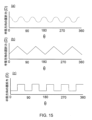
半径方向の曲率屈折力は、環状領域の周りの子午線に関して、最小値X1と最大値X2との間で変化し得て、当該X1及びX2は、両方とも、ベースの半径方向の曲率屈折力よりも大きい。当該X1及びX2は、両方とも、ベースの曲率屈折力よりも大きくてよい。半径方向の曲率屈折力は、環状領域の周りで周期的に変化し得る。当該変化は、正弦波状波形、三角形状波形、四角形(方形)状波形、または、鋸歯状波形、によって定義され得る。半径方向の曲率屈折力は、X1とX2との間で連続的に変化し得る。環状領域の周に沿った(周方向の)位置を角度θによって定義すると、θは0°~360°の間で変化し、90°ごと、45°ごと、20°ごと、または、10°ごとに、半径方向の曲率屈折力に最大値が存在し得る。X1は、+0.5D~+10.0Dの間であり得る。X2は、+2.0D~+20.0Dの間であり得る。 The radial curvature power may vary with respect to a meridian around the annular region between a minimum value X1 and a maximum value X2, both of which are greater than the radial curvature power of the base. Both of which may be greater than the radial curvature power of the base. The radial curvature power may vary periodically around the annular region. The variation may be defined by a sinusoidal waveform, a triangular waveform, a square waveform, or a sawtooth waveform. The radial curvature power may vary continuously between X1 and X2. If the position around the circumference of the annular region is defined by an angle θ, θ may vary between 0° and 360°, and there may be a maximum value in the radial curvature power every 90°, 45°, 20°, or 10°. X1 may be between +0.5D and +10.0D. X2 can be between +2.0D and +20.0D.
代替的及び/または付加的に、環状領域の半径方向のサジタル屈折力は、環状領域の周りの子午線に関して、最小値Y1と最大値Y2との間で変化し得て、当該Y1及びY2は、両方とも、ベースの半径方向のサジタル屈折力よりも大きい。当該Y1及びY2は、両方とも、ベースの半径方向のサジタル屈折力よりも大きくてよい。半径方向のサジタル屈折力は、環状領域の周りで周期的に変化し得る。半径方向のサジタル屈折力の当該周期的変化は、環状領域の全体周りで変改し得るし、あるいは、環状領域の一部周りで変化し得る。当該変化は、正弦波状波形、三角形状波形、または、鋸歯状波形、によって定義され得る。半径方向の曲率屈折力は、Y1とY2との間で連続的に変化し得る。環状領域の周に沿った(周方向の)位置を角度θによって定義すると、θは0°~360°の間で変化し、90°ごと、45°ごと、20°ごと、または、10°ごとに、半径方向のサジタル屈折力に最大値が存在し得る。Y1は、+0.5D~+9.0Dの間であり得る。Y2は、+2.0D~+19.0Dの間であり得る。 Alternatively and/or additionally, the radial sagittal power of the annular region may vary with respect to a meridian around the annular region between a minimum value Y1 and a maximum value Y2, both of which are greater than the radial sagittal power of the base. Both of which may be greater than the radial sagittal power of the base. The radial sagittal power may vary periodically around the annular region. The periodic variation of the radial sagittal power may vary around the entire annular region or around a portion of the annular region. The variation may be defined by a sinusoidal, triangular, or sawtooth waveform. The radial curvature power may vary continuously between Y1 and Y2. The position along the circumference of the annular region is defined by the angle θ, which varies between 0° and 360°, and there may be a maximum in radial sagittal power every 90°, 45°, 20°, or 10°. Y1 may be between +0.5D and +9.0D. Y2 may be between +2.0D and +19.0D.
環状領域の半径方向の曲率屈折力が最小値X1と最大値X2との間で変化する本開示の実施形態では、当該X1及びX2は、両方とも、Yより大きい場合がある。環状領域の半径方向のサジタル屈折力が最小値Y1と最大値Y2との間で変化する本開示の実施形態では、当該Y1及びY2は、両方とも、Xより小さい場合がある。環状領域の半径方向の曲率屈折力が最小値X1と最大値X2との間で変化して環状領域の半径方向のサジタル屈折力が最小値Y1と最大値Y2との間で変化する本開示の実施形態では、半径方向の曲率屈折力及び半径方向のサジタル屈折力の変化は、同位相または異位相であり得る。環状領域の周りの任意の子午線において、半径方向の曲率屈折力は、半径方向のサジタル屈折力よりも大きい場合がある。レンズの半径方向の曲率屈折力が環状領域の周りで一定または略一定を維持するように、環状領域の半径方向のサジタル屈折力と曲率半径との両方が、環状領域の周りの子午線に関して変化し得る。例えば、レンズが+3.0Dの一定の半径方向の曲率屈折力を有する場合、環状領域の周りの子午線に関して、半径方向のサジタル屈折力は、+2.0D~+3.0Dの間で変化し得る。+3.0Dの半径方向のサジタル屈折力を有する領域の場合、環状領域の曲率半径は第1光軸上に中心合わせされるであろう。+2.0Dの半径方向のサジタル屈折力を有する領域の場合、環状領域の曲率中心は第1光軸から離れるようにシフトされ、環状領域の曲率半径は変化し得る。 In embodiments of the present disclosure in which the radial curvature of the annular region varies between a minimum value X1 and a maximum value X2, both X1 and X2 may be greater than Y. In embodiments of the present disclosure in which the radial sagittal power of the annular region varies between a minimum value Y1 and a maximum value Y2, both Y1 and Y2 may be less than X. In embodiments of the present disclosure in which the radial curvature of the annular region varies between a minimum value X1 and a maximum value X2 and the radial sagittal power of the annular region varies between a minimum value Y1 and a maximum value Y2, the changes in the radial curvature power and the radial sagittal power may be in phase or out of phase. At any meridian around the annular region, the radial curvature power may be greater than the radial sagittal power. Both the radial sagittal power and the radius of curvature of the annular region may vary with respect to a meridian around the annular region such that the radial curvature power of the lens remains constant or nearly constant around the annular region. For example, if the lens has a constant radial curvature power of +3.0D, then with respect to the meridian around the annular region, the radial sagittal power may vary between +2.0D and +3.0D. For a region with a radial sagittal power of +3.0D, the radius of curvature of the annular region would be centered on the first optical axis. For a region with a radial sagittal power of +2.0D, the center of curvature of the annular region is shifted away from the first optical axis and the radius of curvature of the annular region may vary.
コンタクトレンズは、少なくとも2つの同心の環状領域を含み得る。少なくとも2つの環状領域の各々について、環状領域の幅の中間の点において、環状領域は、Xの半径方向の曲率屈折力を有し、当該Xは、ベースの半径方向の曲率屈折力よりも大きい。少なくとも2つの環状領域の各々は、光軸から第1距離にある軸外曲率中心を有し得て、その幅の中間の点において、環状領域は、Yの半径方向のサジタル屈折力を有し、当該Yは、ベースの半径方向のサジタル屈折力よりも大きく、当該Yは前記Xよりも小さい。各環状領域は、前述の環状領域の特徴のいずれかを含み得る。少なくとも2つの同心の環状領域を有する実施形態では、各環状領域は、同一の半径方向の曲率屈折力プロファイルと、同一の半径方向のサジタル屈折力プロファイルと、を有し得る、あるいは、各同心環状領域は、異なる半径方向の曲率屈折力プロファイル及び/または半径方向のサジタル屈折力プロファイルを有し得る。少なくとも2つの同心の環状領域を有する実施形態では、環状領域は、ベースの屈折力(すなわち、中央領域と同一の屈折力)を有する領域によって分離され得る。 The contact lens may include at least two concentric annular regions. For each of the at least two annular regions, at a midpoint of the width of the annular region, the annular region has a radial curvature power of X, which is greater than the radial curvature power of the base. Each of the at least two annular regions may have an off-axis center of curvature at a first distance from the optical axis, and at a midpoint of its width, the annular region has a radial sagittal power of Y, which is greater than the radial sagittal power of the base and which is less than X. Each annular region may include any of the features of the annular regions described above. In an embodiment having at least two concentric annular regions, each annular region may have the same radial curvature power profile and the same radial sagittal power profile, or each concentric annular region may have a different radial curvature power profile and/or radial sagittal power profile. In embodiments having at least two concentric annular regions, the annular regions may be separated by a region having the base optical power (i.e., the same optical power as the central region).
コンタクトレンズは、エラストマー材料、シリコーンエラストマー材料、ヒドロゲル材料、または、シリコーンヒドロゲル材料、あるいは、それらの組み合わせ、を含み得る。コンタクトレンズの分野で理解されているように、ヒドロゲルは、水を平衡状態に保持し、シリコーン含有化合物を含まない材料である。シリコーンヒドロゲルは、シリコーン含有化合物を含むヒドロゲルである。本開示の文脈で説明されるように、ヒドロゲル材料及びシリコーンヒドロゲル材料は、少なくとも10%~約90%(wt/wt)の平衡含水率(EWC)を有する。幾つかの実施形態では、ヒドロゲル材料またはシリコーンヒドロゲル材料は、約30%~約70%(wt/wt)のEWCを有する。比較すると、本開示の文脈で説明されるように、シリコーンエラストマー材料は、約0%~10%未満(wt/wt)の含水率を有する。典型的には、本方法または本装置で使用されるシリコーンエラストマー材料は、0.1%~3%(wt/wt)の含水率を有する。好適なレンズ製剤(組成)の例は、以下の米国一般名(USAN)を有するものを含む:メタフィルコン(methafilcon)A、オキュフィルコン(ocufilcon)A、オキュフィルコン(ocufilcon)B、オキュフィルコン(ocufilcon)C、オキュフィルコン(ocufilcon)D、オマフィルコン(omafilcon)A、オマフィルコン(omafilcon)B、コムフィルコン(comfilcon)A、エンフィルコン(enfilcon)A、ステンフィルコン(stenfilcon)A、ファンフィルコン(fanfilcon)A、エタフィルコン(etafilcon)A、セノフィルコン(senofilcon)A、セノフィルコン(senofilcon)B、セノフィルコン(senofilcon)C、ナラフィルコン(narafilcon)A、ナラフィルコン(narafilcon)B、バラフィルコン(balafilcon)A、サムフィルコン(samfilcon)A、ロトラフィルコン(lotrafilcon)A、ロトラフィルコン(lotrafilcon)B、ソモフィルコン(somofilcon)A、リオフィルコン(riofilcon)A、デレフィルコン(delefilcon)A、ベロフィルコン(verofilcon)A、カリフィルコン(kalifilcon)A、等。 The contact lenses may include elastomer materials, silicone elastomer materials, hydrogel materials, or silicone hydrogel materials, or combinations thereof. As understood in the contact lens art, a hydrogel is a material that holds water in equilibrium and does not contain silicone-containing compounds. A silicone hydrogel is a hydrogel that includes silicone-containing compounds. As described in the context of this disclosure, hydrogel and silicone hydrogel materials have an equilibrium water content (EWC) of at least 10% to about 90% (wt/wt). In some embodiments, hydrogel or silicone hydrogel materials have an EWC of about 30% to about 70% (wt/wt). In comparison, as described in the context of this disclosure, silicone elastomer materials have a water content of about 0% to less than 10% (wt/wt). Typically, the silicone elastomer materials used in the present method or device have a water content of 0.1% to 3% (wt/wt). Examples of suitable lens formulations (compositions) include those having the following United States Adequate Names (USAN): methafilcon A, ocufilcon A, ocufilcon B, ocufilcon C, ocufilcon D, omafilcon A, omafilcon B, comfilcon A, enfilcon A, stenfilcon A, fanfilcon A, etafilcon A, senofilcon A, senofilcon B, senofilcon C, senofilcon D ... Senofilcon A, Senofilcon B, Senofilcon C, Narafilcon A, Narafilcon B, Balafilcon A, Samfilcon A, Lotrafilcon A, Lotrafilcon B, Somofilcon A, Riofilcon A, Delefilcon A, Verofilcon A, Kalifilcon A, etc.
代替的に、レンズは、シリコーンエラストマー材料を、含み得る、本質的にそれからなり得る、または、それからなり得る。例えば、レンズは、3~50のショアA硬度を有するシリコーンエラストマー材料を、含み得る、本質的にそれからなり得る、または、それからなり得る。ショアA硬度は、当業者によって理解されているように、従来方法を使用して(例えば、方法DIN53505を使用して)決定され得る。他のシリコーンエラストマー材料が、例えば、NuSil Technology、または、Dow Chemical Company、から取得され得る。 Alternatively, the lens may include, consist essentially of, or consist of a silicone elastomer material. For example, the lens may include, consist essentially of, or consist of a silicone elastomer material having a Shore A hardness of 3 to 50. Shore A hardness may be determined using conventional methods (e.g., using method DIN 53505) as understood by those skilled in the art. Other silicone elastomer materials may be obtained, for example, from NuSil Technology or Dow Chemical Company.
第2の態様によって、本開示は、レンズを製造する方法を提供する。当該方法は、中央領域を備えたコンタクトレンズを形成する工程を備え得て、当該中央領域は、第1光軸と、ベース曲率屈折力と、ベースサジタル屈折力と、を有しており、第1光軸上にある曲率中心に中心合わせされている。当該レンズは、環状領域をも備える。環状領域は、Xの半径方向の曲率屈折力を有する。当該Xは、ベースの半径方向の曲率屈折力よりも大きい。環状領域は、光軸から第1距離である軸外曲率中心を有しており、その幅の中間の点において、環状領域は、Yの半径方向のサジタル屈折力を有しており、当該Yは、ベースの半径方向のサジタル屈折力よりも大きく、当該Yは前記Xよりも小さい。 According to a second aspect, the present disclosure provides a method of manufacturing a lens. The method may include forming a contact lens with a central region having a first optical axis, a base curvature power, and a base sagittal power, the central region being centered on the first optical axis. The lens also includes an annular region. The annular region has a radial curvature power of X, which is greater than the radial curvature power of the base. The annular region has an off-axis center of curvature that is a first distance from the optical axis, and at a point midway through its width, the annular region has a radial sagittal power of Y, which is greater than the radial sagittal power of the base and which is less than X.
レンズは、前述の特徴のいずれかを含み得る。 The lens may include any of the features described above.
当該製造方法は、凹レンズ形成面を有する雌型部材と、凸レンズ形成面を有する雄型部材と、を形成する工程を含み得る。当該方法は、雌型部材と雄型部材との間のギャップをバルクレンズ材料で充填する工程を含み得る。当該方法は、バルクレンズ材料を硬化させてレンズを形成する工程を更に含み得る。 The manufacturing method may include forming a female member having a concave lens-forming surface and a male member having a convex lens-forming surface. The method may include filling a gap between the female member and the male member with bulk lens material. The method may further include curing the bulk lens material to form a lens.
コンタクトレンズは、旋盤加工を用いて形成され得る。レンズは、キャスト成形プロセス、スピンキャスト成形プロセス、または、旋盤加工プロセス、あるいは、それらの組み合わせ、によって形成され得る。当業者によって理解されているように、キャスト成形とは、凹レンズ部材形成面を有する雌型成形部材と凸レンズ部材形成面を有する雄型成形部材との間にレンズ成形材料を入れることでレンズを成形する工程を指す。 Contact lenses may be formed using a lathe process. Lenses may be formed by a cast molding process, a spin cast molding process, or a lathe process, or a combination thereof. As understood by those skilled in the art, cast molding refers to the process of forming a lens by placing a lens molding material between a female mold member having a concave lens member forming surface and a male mold member having a convex lens member forming surface.
レンズを製造する方法は、コンタクトレンズを設計する工程を備え得て、設計されるレンズは、本開示の一実施形態に従ったレンズであり、前述の特徴のいずれかを含む。当該レンズは、モデリング(モデル化)を使用して設計され得て、当該モデリングは、コンピュータで実装されるモデリングであり得る。 The method of manufacturing a lens may include designing a contact lens, the designed lens being a lens according to an embodiment of the present disclosure and including any of the features described above. The lens may be designed using modeling, which may be computer-implemented modeling.
当該方法は、第1コンタクトレンズをモデリングする工程を備え得る。第1コンタクトレンズは、中央領域を有し得て、当該中央領域は、第1光軸を有する。当該中央領域は、ベース屈折力を有し得て、第1光軸上にある曲率中心上に中心合わせされ得る。第1コンタクトレンズは、中央領域を取り囲む環状領域を有し得る。環状領域は、第1光軸上に中心合わせされた曲率半径を有し得て、環状領域の当該曲率が追加屈折力を生じさせ、環状領域の正味の屈折力は、ベース屈折力と追加屈折力との合計である。当該方法は、第2コンタクトレンズをモデリングする工程を備え得る。第2コンタクトレンズは、第1コンタクトレンズと同一の中央領域を有し得る。第2レンズの中央領域は、第1レンズと同一のベース屈折力を有し得て、第1光軸上にある曲率中心上に中心合わせされ得る。第2コンタクトレンズは、中央領域を取り囲む環状領域を有し得る。第2レンズの環状領域は、第1光軸上に中心合わせされた曲率半径を有し得て、第2レンズの第2環状領域の当該曲率が、第1コンタクトレンズの追加屈折力よりも大きい追加屈折力を生じさせ得る。第2レンズの正味の屈折力は、第2レンズのベース屈折力と追加屈折力との合計である。第2レンズの正味の屈折力は、第1レンズの正味の屈折力よりも大きい場合がある。レンズを設計する方法は、モデル内で、当該環状領域の内側の縁が固定された状態を維持しながら、当該環状領域の外周または外縁が第1レンズの環状領域の外縁に一致するように、第2レンズの環状領域を傾斜させる工程を含み得る。第2レンズの環状領域を傾けると、当該環状領域の曲率中心は第1光軸から離れる。第2レンズの環状領域を傾けると、第3のモデル化されたレンズ、すなわち、傾斜された第2レンズが生じるであろう。第3レンズ、すなわち、傾斜された第2レンズは、傾斜されていない第2コンタクトレンズと同一の正味の屈折力を生じさせる環状領域を有するが、軸外の曲率中心を伴う。 The method may include modeling a first contact lens. The first contact lens may have a central region, the central region having a first optical axis. The central region may have a base refractive power and may be centered on a center of curvature that is on the first optical axis. The first contact lens may have an annular region surrounding the central region. The annular region may have a radius of curvature centered on the first optical axis, the curvature of the annular region producing an add refractive power, and the net refractive power of the annular region is the sum of the base refractive power and the add refractive power. The method may include modeling a second contact lens. The second contact lens may have the same central region as the first contact lens. The central region of the second lens may have the same base refractive power as the first lens and may be centered on a center of curvature that is on the first optical axis. The second contact lens may have an annular region surrounding the central region. The annular region of the second lens may have a radius of curvature centered on the first optical axis, and the curvature of the second annular region of the second lens may produce an add power greater than the add power of the first contact lens. The net power of the second lens is the sum of the base power and the add power of the second lens. The net power of the second lens may be greater than the net power of the first lens. The method of designing a lens may include tilting the annular region of the second lens in the model such that the periphery or outer edge of the annular region coincides with the outer edge of the annular region of the first lens, while keeping the inner edge of the annular region fixed. Tilting the annular region of the second lens moves the center of curvature of the annular region away from the first optical axis. Tilting the annular region of the second lens will result in a third modeled lens, i.e., a tilted second lens. The third lens, i.e. the tilted second lens, has an annular area that produces the same net optical power as the non-tilted second contact lens, but with an off-axis center of curvature.
レンズを製造する方法は、モデル化された第3コンタクトレンズ(すなわち、傾斜された第2レンズ)に基づいてレンズを製造する工程を備え得る。第3のモデル化されたレンズに基づくレンズは、第1のモデル化されたレンズに基づくレンズよりも高い曲率を有するため、当該レンズはより高い正の球面収差を有し得る。第3のコンタクトレンズ設計に基づいて製造されるレンズは、また、第1または第2のモデル化されたレンズに基づくレンズと比較して、拡張された焦点深度を有し得る。 The method of manufacturing a lens may include manufacturing a lens based on a modeled third contact lens (i.e., the tilted second lens). The lens based on the third modeled lens may have a higher curvature than the lens based on the first modeled lens, such that the lens has a higher positive spherical aberration. The lens manufactured based on the third contact lens design may also have an extended depth of focus compared to the lenses based on the first or second modeled lenses.
図1Aは、近視の進行を低減するために近視性デフォーカス像を提供する治療ゾーンを用いるコンタクトレンズの概略平面図を示す。図1Bは、図1Aのレンズの概略側面図である。レンズ1は、概ね瞳孔を覆う光学ゾーン2と、虹彩の上方に位置する周辺ゾーン4と、を備える。周辺ゾーン4は、レンズのサイズを増大して当該レンズ1をより扱いやすくし、当該レンズ1の回転を防止するためのバラストを提供し、及び、レンズ1の着用者の快適性を改善する形状領域を提供する、といったことを含む機械的機能を提供する。光学ゾーン2は、レンズ1の光学機能を提供し、当該光学ゾーン2は、環状領域3及び中央領域5を含む。レンズ1は、ベースの半径方向の曲率屈折力を有し、それは、ベースの半径方向のサジタル屈折力と等しい。ベースの屈折力は、レンズ1の表面の曲率半径から帰結する。中央領域5の曲率中心は、(図2Aに示される)第1光軸19上にある。環状領域3は、ベースの半径方向の曲率屈折力よりも大きい半径方向の曲率屈折力を有する。環状領域3の半径方向の曲率屈折力は、環状領域3の曲率半径6によって提供され、当該曲率半径6は、図3に示されるように、中央領域5の曲率半径7よりも小さい。環状領域3の曲率中心は、第1光軸19上にある。環状領域3は、中央領域5よりも大きい屈折力を有する。図2Aに示されるように、環状領域3の焦点11及び中央領域5の焦点15は、共通の光軸19を共有する。環状領域3の焦点11は、近位焦点面13上にあり、中央領域5の焦点は、遠位焦点面17上にあり、当該遠位焦点面17は、レンズの後面から更に離れている。図2Cに示されるように、無限遠の点源の場合、中央領域5によって焦点合わせされる光線は、遠位焦点面17において焦点画像(焦点合わせされた像)23を形成する。中央領域5によって焦点合わせされる光線は、また、近位焦点面13において焦点が合っていない(焦点合わせされていない)ぼやけ(blur)スポット27を生成する。
1A shows a schematic plan view of a contact lens using a treatment zone that provides a myopic defocused image to reduce the progression of myopia. FIG. 1B shows a schematic side view of the lens of FIG. 1A. The
図2Bに示されるように、環状領域3によって焦点合わせされる光線は、近位焦点面13において焦点画像21を形成する。環状領域3によって焦点合わせされる光線は、近位焦点面13の後で発散し、当該発散光線は、遠位焦点面17において焦点が合っていない(焦点合わせされていない)環状(輪状)画像25を生成する。前述のように、焦点が合っていない環状画像25は、レンズ1の着用者が焦点の合った遠方画像の周りに「ハロー」を見る結果となり得る。
2B, the light rays focused by the
図4Aは、図1A及び図1Bに示されるレンズ1の半径方向のサジタル屈折力の変化を示すプロット(グラフ)31であり、図4Bは、図1A及び図1Bに示されるレンズ1の半径方向の曲率屈折力の変化を示すプロット(グラフ)33である。図4A及び図4Bは、レンズ1の半径方向の直径に沿った屈折力変化を示す。このレンズ1の場合、環状領域3が中央領域5よりも大きい屈折力を有するため、及び、環状領域3が軸上曲率中心を有するため、半径方向のサジタル屈折力(曲線35によって示される)は、中央領域5に亘るよりも環状領域3に亘る方が大きい。半径方向の曲率屈折力(曲線37によって示される)も、中央領域5に亘るよりも環状領域3に亘る方が大きい。
4A is a
図5Aは、非共軸光学系を有する別のコンタクトレンズ101の概略平面図を示す。図5Bは、図5Aのレンズ101の概略側面図である。図1Aのレンズ1と同様に、レンズ101は、概ね瞳孔を覆う光学ゾーン102と、虹彩の上方に位置する周辺ゾーン104と、を備える。レンズ101は、概ね瞳孔を覆う光学ゾーン102と、虹彩の上方に位置する周辺ゾーン104と、を備える。周辺ゾーン104は、レンズのサイズを増大して当該レンズ101をより扱いやすくし、当該レンズ101の回転を防止するためのバラストを提供し、及び、レンズ101の着用者の快適性を改善する形状領域を提供する、といったことを含む機械的機能を提供する。光学ゾーン102は、レンズ101の光学機能を提供し、当該光学ゾーン102は、環状領域103及び中央領域105を含む。レンズ101は、ベースの半径方向の曲率屈折力を有し、それは、ベースの半径方向のサジタル屈折力と等しい。ベースの屈折力は、レンズ101の表面の曲率半径から帰結する。中央領域105の曲率中心は、(図6Aに示される)第1光軸119上にある。環状領域103は、ベースの半径方向の曲率屈折力よりも大きい半径方向の曲率屈折力を有する。環状領域103の半径方向の曲率屈折力は、環状領域103の曲率半径によって提供され、当該曲率半径は、中央領域105の曲率半径よりも小さい。しかしながら、図1Aのレンズ1とは対照的に、図5A及び図5Bに示されるレンズ101の場合、環状領域103の曲率は、単一の球面によって規定されることができず、環状領域103の曲率中心は、第1光軸119上にない。これは、図6Dに示されている。環状領域103は、中央領域105に対して傾斜されており、環状領域103の外縁は、その内縁に対して、図1A及び図1Bのレンズ1の場合におけるよりも高い(図5B参照)。このことが、環状領域103の半径方向のサジタル屈折力を変化させるが、環状領域103の半径方向の曲率屈折力は変化させない。図6Dに示されるように、中央領域105の前面は、より大きな半径の球体107の表面の一部を規定する。環状領域103の前面は、より小さい半径を有する湾曲した環状面106を規定する。
FIG. 5A shows a schematic plan view of another
遠位焦点面117で、中央領域105を通過する光線が焦点合わせ(集束)される。環状領域103は、光学的ビームストップとして作用し、これは、図6Cに示されるように、遠位焦点面117において光124の小さなスポットサイズ133をもたらす。
At the distal
近位焦点面113には、単一の像は形成されない。図6Bに示されるように、近位焦点面113では、無限遠の点源に対して、中央領域105を通過する光線は、図1A及び図1B並びに図2A及び図2Bのレンズと同様、ぼやけ(blur)円128を生成する。一方、環状領域103を通過する遠方の点源からの光線は、焦点合わせされた環122を生成し、これは、図6Bに示されるように、ぼやけ円128を取り囲んでいる。図6Bは、遠方の点源に対して生成される光パターンを示している。図1A及び図1Bのレンズ1とは対照的に、図5A及び図5Bのレンズ101は、近位物体に目が順応する必要性を回避するために使用され得るであろう、近位焦点面113における単一画像または軸上画像を生成することがない。遠方にある拡張物体の場合、近位焦点面113において形成される焦点画像は、(i)環状領域103の屈折力を有する従来のレンズで得られるであろう当該拡張物体の焦点画像と、(ii)環状領域103の光学効果を表す光学伝達関数と、の畳み込みである。
No single image is formed in the near
図1A及び図1Bのレンズとは対照的に、環状または「ハロー」効果は、遠位焦点面117において発生しない。
In contrast to the lenses of Figures 1A and 1B, no annular or "halo" effect occurs at the distal
図7Aは、図5A及び図5Bに示されたレンズ101の半径方向のサジタル屈折力の変化を示すプロット(グラフ)131である。図7Bは、図5A及び図5Bに示されたレンズ101の半径方向の曲率屈折力の変化を示すプロット(グラフ)133である。図7A及び図7Bは、レンズ101の半径方向の直径に沿った屈折力変化を示す。このレンズ101の場合、環状領域103が中央領域105よりも大きい屈折力を有するため、これは、半径方向の曲率屈折力(曲線137によって示される)が、中央領域105に亘るよりも環状領域103に亘る方が大きい、ということを意味する。しかしながら、環状領域103は中央領域105に対して傾斜されて、環状領域103は軸外曲率中心を有している。中央領域105に対する環状領域103の傾斜は、曲線135によって示されるように、中央領域105と環状領域103との間の境界において、半径方向のサジタル屈折力が中央領域の半径方向のサジタル屈折力よりも更に負であることを意味する。半径方向のサジタル屈折力は、環状領域103の外縁に向かう半径方向距離の増大に応じて増大し得る。
7A is a
図8Aは、本開示の一実施形態に係るコンタクトレンズ201の概略平面図である。図1A及び図1Bのレンズ1並びに図5A及び図5Bのレンズ101と同様に、レンズ201は、概ね瞳孔を覆う光学ゾーン202と、虹彩の上方に位置する周辺ゾーン204と、を備える。周辺ゾーン204は、レンズのサイズを増大して当該レンズ201をより扱いやすくし、当該レンズ201の回転を防止するためのバラストを提供し、及び、レンズ201の着用者の快適性を改善する形状領域を提供する、といったことを含む機械的機能を提供する。光学ゾーン202は、レンズ201の光学機能を提供し、当該光学ゾーン202は、環状領域203及び中央領域205を含む。レンズ201の中央領域205は、ベースの半径方向の曲率屈折力を有し、それは、ベースの半径方向のサジタル屈折力と等しい。本開示のこの例示的な実施形態では、中央領域のベースの半径方向の曲率屈折力は、0.0Dであり、これは、中央領域205のベースの半径方向のサジタル屈折力に等しい。このベースの屈折力は、レンズ201の表面の曲率半径から帰結する。中央領域205の曲率中心244は、(図9に示される)第1光軸219上にある。環状領域203は、ベースの半径方向の曲率屈折力よりも大きい半径方向の曲率屈折力を有する。環状領域203の半径方向の曲率屈折力は、環状領域203の曲率半径によって提供され、当該曲率半径は、中央領域205の曲率半径よりも小さい。
8A is a schematic plan view of a
環状領域の幅の中間の点A(図8A及び図8Bに示されている)において、環状領域の半径方向の曲率屈折力は、約+3.5Dの値を有する。図8A及び図8Bに示されている例示的なレンズ201の場合、半径方向の曲率屈折力は、所与の半径方向位置において、環状領域203の周りの全ての子午線で一定である。これは、図8A及び図8Bに示される破線曲線241に沿って、半径方向の曲率屈折力が、環状領域203の幅の中間の点において、同一値を有することを意味する。破線曲線241は、環状領域203の周りに延びる曲線である。本開示のこの例示的な実施形態では、Xは約+3.5Dである。図5A及び図5Bに示されるレンズと同様に、レンズ201の環状領域203は、中央領域205に対して傾斜されており、環状領域203の曲率中心243は、第1光軸219からオフセットされている。これは、図9に示されている。環状領域203を中央領域205に対して傾斜させることは、中央領域205と環状領域203との間の境界における半径方向のサジタル屈折力を減少させる。環状領域203の幅の中間の点Aにおいて、半径方向のサジタル屈折力は値Yを有しており、これは、ベースの半径方向のサジタル屈折力よりも大きいが、Xよりも小さい。この例示的な実施形態の場合、Yは約+2.25Dであり、半径方向のサジタル屈折力は、所与の半径方向位置において、環状領域203の周りの全ての子午線で一定である。これは、図8A及び図8Bに示される破線曲線241に沿って、半径方向のサジタル屈折力が同一値を有することを意味する。破線曲線241は、環状領域203の周りに延びる曲線である。
At point A (shown in FIGS. 8A and 8B) midway through the width of the annular region, the radial curvature of the annular region has a value of about +3.5D. For the
遠位焦点面217では、中央領域205を通過する光線が焦点を合わせられる。環状領域203を通過する光線は、サジタル追加焦点面218に向けて案内される。
At the distal
図10Aは、図8A及び図8Bに示されるレンズ201の半径方向の(ラジアル)直径に亘る曲率屈折力の変化を示すプロット(グラフ)231である。このプロット231は、半径方向及び周方向の曲率屈折力の平均を示す。中央領域205の全体に亘って、レンズ201の曲率屈折力は一定であり、概ねゼロである。中心領域205と環状領域203との間の境界では、曲線235によって示されるように、曲率屈折力が急激な増大を示す。これは、半径方向の曲率屈折力が増大するためである。中央領域205と環状領域203との間の境界では、周方向の曲率屈折力は大きく変化しないが、半径方向の曲率屈折力は増大するため、中央領域205との間の当該境界で、平均の曲率屈折力(曲線235によって示される)は、周方向の曲率屈折力と半径方向の曲率屈折力との平均まで増大する。
10A is a
図10Bは、図8A及び図8Bに示されるレンズ201の半径方向の(ラジアル)直径に亘るサジタル屈折力の変化を示すプロット(グラフ)233である。このプロット233は、半径方向及び周方向のサジタル屈折力の平均を示す。レンズ201の中央領域205の全体に亘って、サジタル屈折力は一定であり、0.0Dの値を有する。中心領域205と環状領域203との間の境界では、曲線237によって示されるように、半径方向のサジタル屈折力の増大のために、環状領域203のサジタル屈折力は急激に増大する。半径方向のサジタル屈折力は、環状領域203の幅に亘って半径方向外側に、概ね直線的に増大する。軸外追加屈折力環状領域203を有するレンズの図7Aに示されるサジタル屈折力曲線とは対照的に、中央領域205と環状領域203との間の境界でサジタル屈折力にディップ(へこみ)は存在しない。これは、中央領域205と環状領域203との間の境界において半径方向のサジタル屈折力を増大するように、環状領域203が中央領域に対して傾斜されているためである。中央領域205と環状領域205との間の境界におけるサジタル屈折力の増大は、(例えば、図1A及び図1Bに示されるような)軸上追加屈折力環状領域を有するレンズの場合ほど大きくない。
10B is a
図11Aに示されるように、図8A及び図8Bに示されるレンズ201の場合、遠位焦点面217において、中央領域205を通過する光線が、図11Bに示されるように、焦点の合った(焦点合わせされた)画像223を形成する。環状領域203を通過する光線は、遠位焦点面217において、焦点の合っていない環225を生成する。図11Cに示されるように、無限遠の点光源について、第1近位焦点面218において、中心領域205を通過する光線が第1ぼやけ円227を生成し、環状領域203を通過する光線が第2ぼやけ円229を生成する。図11Dに示されるように、第2近位焦点面220において、中心領域205を通過する光線が第3ぼやけ円231を生成し、環状領域203を通過する光線が第3ぼやけ円231内に焦点の合った環233を生成する。
図12Aは、本開示の一実施形態によるコンタクトレンズ301の概略平面図を示している。図8A及び図8Bのレンズ201と同様に、レンズ301は、概ね瞳孔を覆う光学ゾーン302と、虹彩の上方に位置する周辺ゾーン304と、を備える。周辺ゾーン304は、レンズのサイズを増大して当該レンズ301をより扱いやすくし、当該レンズ301の回転を防止するためのバラストを提供し、及び、レンズ301の着用者の快適性を改善する形状領域を提供する、といったことを含む機械的機能を提供する。光学ゾーン302は、レンズ301の光学機能を提供し、当該光学ゾーン302は、環状領域303及び中央領域305を含む。レンズ301は、ベースの半径方向の曲率屈折力を有し、それは、ベースの半径方向のサジタル屈折力と等しい。本開示のこの例示的な実施形態では、中央領域のベースの半径方向の曲率屈折力は、-2.0Dであり、中央領域205のベースの半径方向のサジタル屈折力も、-2.0Dである。ベースの屈折力は、レンズ301の表面の曲率半径から帰結する。中央領域305の曲率中心は、第1光軸上にある。環状領域303は、ベースの半径方向の曲率屈折力よりも大きい半径方向の曲率屈折力を有する。環状領域303の半径方向の曲率屈折力は、環状領域303の周りの子午線によって変化する。この例示的な実施形態では、半径方向の曲率屈折力は、任意の子午線に沿って半径方向外側に概ね一定である。図12A及び図12Bの破線341によって示される、環状領域303の幅の中間で環状領域3030を周回する曲線に沿って、半径方向の曲率屈折力は、最小値X1と最大値X2との間で変化する。当該X1及びX2は、両方とも、中央領域305のベースの曲率屈折力よりも大きい。XIは、+2.0Dであり、X2は、+10.0Dである。半径方向の曲率屈折力は、環状領域の周りで正弦波状に変化し、そのプロファイルが図14に示されている。環状領域303の周に沿った(周方向の)位置を角度θを用いて定義すると、θは0°~360°の間で変化し、この例示的な実施形態では、180°ごとに、半径方向の曲率屈折力が、環状領域303の幅の中間の点において、最大値X2を有し、すなわち、点A及び点Cにおいて半径方向の曲率がX2である。半径方向の曲率屈折力は、180°ごとに、環状領域303の幅の中間の点において、最小値X1を有し、すなわち、点B及び点Dにおいて半径方向の曲率がX1である。
8A and 8B, at the distal
FIG. 12A shows a schematic plan view of a
環状領域303の半径方向の曲率屈折力は、環状領域303の表面の曲率から帰結する。環状領域303の周りの全ての点において、環状領域303の曲率半径は、中央領域305の曲率半径307よりも小さい。環状領域303の周りの全ての点において、環状領域303は軸外曲率中心を有する。この例示的な実施形態では、環状領域303の曲率半径は子午線によって変化し、これが、変化する半径方向の曲率屈折力を生じさせる。図13Aに示されるように、半径方向の曲率が最大値を有する半径方向直径(図12Aの線E-E)に沿って、環状領域303の曲率半径306eは最小となる(図13A)。図13Bに示されるように、半径方向の曲率が最小値を有する半径方向直径(図12Aの線F-F)に沿って、環状領域303の曲率半径306fは最大となる。
The radial curvature power of the
このレンズ301の場合、環状領域303の幅の中間の点において、環状領域303の周りで半径方向のサジタル屈折力は一定値Yである。図14に模式的に示されるように、YはXより小さいが、Yはレンズ301の中央領域305のベース屈折力より大きい。
For this
本開示の他の実施形態(不図示)では、レンズは、図8A乃至図11Dに示されて説明されたレンズと同様であるが、環状領域の幅の中間の点A(図8A及び図8Bに示される)において、環状領域の半径方向の曲率屈折力は、中央領域のベースの半径方向の曲率屈折力よりも約+10.0D大きく(すなわち、半径方向の曲率追加屈折力は約+10.0Dである)、環状領域の半径方向のサジタル屈折力は、中央領域のベースの半径方向のサジタル屈折力よりも約+2.0D大きい(すなわち、半径方向のサジタル追加屈折力は約+2.0Dである)。 In another embodiment (not shown) of the present disclosure, the lens is similar to the lens shown and described in Figures 8A-11D, except that at point A (shown in Figures 8A and 8B) midway through the width of the annular region, the radial curvature power of the annular region is about +10.0D greater than the radial curvature power of the base of the central region (i.e., the radial curvature add power is about +10.0D) and the radial sagittal power of the annular region is about +2.0D greater than the radial sagittal power of the base of the central region (i.e., the radial sagittal add power is about +2.0D).
本開示の他の実施形態(不図示)では、レンズは、図8A乃至図11Dに示されて説明されたレンズと同様であるが、環状領域の幅の中間の点Aにおいて、環状領域の半径方向の曲率屈折力は、中央領域のベースの半径方向の曲率屈折力よりも約+12.0D大きく(すなわち、半径方向の曲率追加屈折力は約+12.0Dである)、環状領域の半径方向のサジタル屈折力は、中央領域のベースの半径方向のサジタル屈折力よりも約+4.0D大きい(すなわち、半径方向のサジタル追加屈折力は約+4.0Dである)。有利なことに、このようなレンズは、中央領域と環状領域との間の境界において半径方向のサジタル屈折力に急激な増大を示す。半径方向のサジタル屈折力の増大は、+2.0Dを超える場合がある。比較的小さい瞳孔径を有するレンズ着用者(例えば、若いレンズ着用者)の場合、中央領域と環状領域との間の境界での半径方向のサジタル屈折力のこの急激な増大が、環状領域の治療効果を改善させ得る。 In another embodiment of the present disclosure (not shown), the lens is similar to the lens shown and described in Figures 8A-11D, but at point A midway through the width of the annular region, the radial curvature power of the annular region is about +12.0D greater than the radial curvature power of the base of the central region (i.e., the radial curvature add power is about +12.0D), and the radial sagittal power of the annular region is about +4.0D greater than the radial sagittal power of the base of the central region (i.e., the radial sagittal add power is about +4.0D). Advantageously, such a lens exhibits an abrupt increase in radial sagittal power at the boundary between the central region and the annular region. The increase in radial sagittal power may be greater than +2.0D. For lens wearers with relatively small pupil diameters (e.g., young lens wearers), this sudden increase in radial sagittal power at the boundary between the central and annular regions may improve the therapeutic effect of the annular region.
本開示の他の実施形態(不図示)では、レンズは、図8A乃至図11Dに示されて説明されたレンズと同様であるが、環状領域の幅の中間の点A(図8A及び図8Bに示される)において、環状領域の半径方向の曲率屈折力は、中央領域のベースの半径方向の曲率屈折力よりも約+11.0D大きく(すなわち、半径方向の曲率追加屈折力は約+11.0Dである)、環状領域の半径方向のサジタル屈折力は、中央領域のベースの半径方向のサジタル屈折力よりも約+3.0D大きい(すなわち、半径方向のサジタル追加屈折力は約+3.0Dである)。 In another embodiment (not shown) of the present disclosure, the lens is similar to the lens shown and described in Figures 8A-11D, except that at point A (shown in Figures 8A and 8B) midway through the width of the annular region, the radial curvature power of the annular region is about +11.0D greater than the radial curvature power of the base of the central region (i.e., the radial curvature add power is about +11.0D) and the radial sagittal power of the annular region is about +3.0D greater than the radial sagittal power of the base of the central region (i.e., the radial sagittal add power is about +3.0D).
本開示の他の実施形態(不図示)では、レンズは、図8A乃至図11Dに示されて説明されたレンズと同様であるが、環状領域の幅の中間の点A(図8A及び図8Bに示される)において、環状領域の半径方向の曲率屈折力は、中央領域のベースの半径方向の曲率屈折力よりも約+12.0D大きく(すなわち、半径方向の曲率追加屈折力は約+12.0Dである)、環状領域の半径方向のサジタル屈折力は、中央領域のベースの半径方向のサジタル屈折力よりも約+3.0D大きい(すなわち、半径方向のサジタル追加屈折力は約+3.0Dである)。 In another embodiment (not shown) of the present disclosure, the lens is similar to the lens shown and described in Figures 8A-11D, except that at point A (shown in Figures 8A and 8B) midway through the width of the annular region, the radial curvature power of the annular region is about +12.0D greater than the radial curvature power of the base of the central region (i.e., the radial curvature add power is about +12.0D) and the radial sagittal power of the annular region is about +3.0D greater than the radial sagittal power of the base of the central region (i.e., the radial sagittal add power is about +3.0D).
本開示の他の実施形態(不図示)では、レンズは、図8A乃至図11Dに示されて説明されたレンズと同様であるが、環状領域の幅の中間の点A(図8A及び図8Bに示される)において、環状領域の半径方向の曲率屈折力は、中央領域のベースの半径方向の曲率屈折力よりも約+10.0D大きく(すなわち、半径方向の曲率追加屈折力は約+10.0Dである)、環状領域の半径方向のサジタル屈折力は、中央領域のベースの半径方向のサジタル屈折力よりも約+3.0D大きい(すなわち、半径方向のサジタル追加屈折力は約+3.0Dである)。本開示の他の実施形態では、レンズは、子午線に沿って段階的(ステップワイズ)にまたは鋸歯状に変化する半径方向の曲率屈折力を有する環状領域を備え得る。当該変化は、周期的であっても非周期的であってもよい。半径方向の曲率屈折力のピークは、180°ごと、90°ごと、20°ごと、10°ごと、または、5°ごと、に存在し得る。例として、半径方向の屈折力の周期的な変化(半径方向のサジタル屈折力または曲率屈折力の変化であり得る)が、図15A乃至図15Cに示されている。 In another embodiment of the present disclosure (not shown), the lens is similar to the lens shown and described in FIGS. 8A-11D, except that at point A (shown in FIGS. 8A and 8B) midway through the width of the annular region, the radial curvature power of the annular region is about +10.0 D greater than the radial curvature power of the base of the central region (i.e., the radial curvature add power is about +10.0 D) and the radial sagittal power of the annular region is about +3.0 D greater than the radial sagittal power of the base of the central region (i.e., the radial sagittal add power is about +3.0 D). In another embodiment of the present disclosure, the lens may include an annular region having a radial curvature power that varies stepwise or sawtooth-like along the meridian. The variation may be periodic or aperiodic. The radial curvature power peaks may occur every 180°, 90°, 20°, 10°, or 5°. By way of example, a periodic change in radial power (which may be a change in radial sagittal power or curvature power) is shown in Figures 15A-15C.
本開示の他の実施形態では、半径方向の曲率屈折力と半径方向のサジタル屈折力との両方が、環状領域の周りの子午線によって変化し得る。半径方向のサジタル屈折力の変化は、半径方向の曲率屈折力の変化と同位相であってもよいし、異位相であってもよい。環状領域の周の全ての点において、半径方向のサジタル屈折力は半径方向の曲率屈折力よりも小さくてよいが、中央領域のベースの屈折力よりも大きくてよい。 In other embodiments of the present disclosure, both the radial curvature power and the radial sagittal power may vary with meridian around the annular region. The change in radial sagittal power may be in phase or out of phase with the change in radial curvature power. At all points around the circumference of the annular region, the radial sagittal power may be less than the radial curvature power but greater than the base power of the central region.
本開示の他の実施形態では、レンズは、2以上の同心の環状領域を含み得る。当該環状領域の各々について、環状領域の幅の中間の点において、環状領域は、Xの半径方向の曲率屈折力を有し、当該Xは、ベースの半径方向の曲率屈折力よりも大きい。少なくとも2つの環状領域の各々が、光軸から第1距離にある軸外曲率中心を有し得て、その幅の中間の点において、環状領域は、半径方向のサジタル屈折力Yを有し、当該Yは、ベースの半径方向のサジタル屈折力よりも大きく、当該Yは前記Xよりも小さい。各同心環状領域は、ベース屈折力(すなわち、中央領域と同一の屈折力)を有する領域によって分離され得る。 In other embodiments of the present disclosure, the lens may include two or more concentric annular regions. For each of the annular regions, at a midpoint of the width of the annular region, the annular region has a radial curvature power of X, where X is greater than the radial curvature power of the base. Each of the at least two annular regions may have an off-axis center of curvature at a first distance from the optical axis, where at a midpoint of the width, the annular region has a radial sagittal power Y, where Y is greater than the radial sagittal power of the base, where Y is less than X. Each concentric annular region may be separated by a region having a base power (i.e., the same power as the central region).
本開示の他の実施形態では、レンズは、2以上の同心の環状領域を含み得る。当該環状領域の少なくとも1つが、図5A及び図6Aに示されるような環状領域であり、残りの環状領域の少なくとも1つが、環状領域の幅の中間の点において、Xの半径方向の曲率屈折力を有し、当該Xは、ベースの半径方向の曲率屈折力よりも大きい。当該少なくとも2つの環状領域の各々が、光軸から第1距離にある軸外曲率中心を有し得て、その幅の中間の点において、環状領域は、半径方向のサジタル屈折力Yを有し、当該Yは、ベースの半径方向のサジタル屈折力よりも大きく、当該Yは前記Xよりも小さい。 In other embodiments of the present disclosure, the lens may include two or more concentric annular regions, at least one of which is an annular region as shown in FIG. 5A and FIG. 6A, and at least one of the remaining annular regions has a radial curvature power of X at a midpoint of the width of the annular region, where X is greater than the radial curvature power of the base. Each of the at least two annular regions may have an off-axis center of curvature at a first distance from the optical axis, and at a midpoint of its width, the annular region has a radial sagittal power Y, where Y is greater than the radial sagittal power of the base, where Y is less than X.
図16は、コンタクトレンズを設計する方法501を示しており、当該レンズは、本開示の一実施形態に従ったレンズである。最初の工程503において、当該方法は、第1コンタクトレンズをモデリングする(モデル化する)工程を含む。第1コンタクトレンズは、中央領域を有し、当該中央領域は、第1光軸を有する。中央領域は、ベース屈折力を有しており、第1光軸上にある曲率中心に中心合わせされている。この例では、第1コンタクトレンズの中央領域は、-3.0Dのベース屈折力を有している。第1コンタクトレンズは、中央領域を取り囲む環状領域を有している。当該環状領域は、第1光軸上に中心合わせされた曲率半径を有する。当該環状領域の曲率が、追加屈折力を生じさせる。この例では、環状領域は、+2.0Dの追加屈折力を生じさせる曲率を有する。環状領域の正味の屈折力は、ベース屈折力と追加屈折力との合計であり、この例では、環状領域の正味の屈折力は、-1.0Dである。
2番目の工程505において、当該方法は、第2コンタクトレンズをモデリングする工程を含む。第2コンタクトレンズは、第1コンタクトレンズと同一の中央領域を有しており、従って、この例では、第2コンタクトレンズは、-3.0Dのベース屈折力を有している。第2コンタクトレンズも、第1光軸上にある曲率中心に中心合わせされている。第2コンタクトレンズも、中央領域を取り囲む環状領域を有している。第2レンズの環状領域は、第1光軸上に中心合わせされた曲率半径を有するが、当該環状領域の曲率は、第1レンズの追加屈折力よりも大きな追加屈折力を生じさせる。この例では、第2環状領域の曲率は、+4.0Dの追加屈折力を生じさせる。第2レンズの正味の屈折力は、ベース屈折力と追加屈折力との合計であり、この例では、第2レンズの正味の屈折力は、+1.0Dである。3番目の工程507において、当該方法は、モデル内で、第2環状領域の内縁を固定したまま、第2環状領域の外縁が第1レンズの環状領域の外縁と一致するように第2レンズの環状領域を傾斜させる工程を含む。これは、傾斜されていない第2レンズと同一の正味の屈折力を伴う環状領域を備えた第3レンズ(傾斜された第2レンズに対応)を生成する。この例では、第3レンズ、すなわち、傾斜された第2レンズが、+1.0Dの正味の屈折力を有する環状領域を備えるが、曲率中心は第1光軸上にはない。
FIG. 16 illustrates a
In a
図17は、前述のレンズを設計する方法の一部としてモデル化された3つのモデル化レンズ601、603、605の概略図である。当該3つのレンズは、第1光軸上に中心合わせされた、-3.0Dのベース屈折力を提供する曲率を有する、共通の中央領域607を共有する。第1レンズ601は、+2.0Dの追加屈折力を生じさせる曲率を有する環状領域601aを備え、当該環状領域の正味の屈折力は、-1.0Dである。第1レンズ601の環状領域601aの曲率中心は、第1光軸上に中心合わせされている。第2レンズ603は、+4.0Dの追加屈折力を生じさせる曲率を有する環状領域603aを備え、当該環状領域の正味の屈折力は、+1.0Dである。第2レンズ603の環状領域603aの曲率中心も、第1光軸上に中心合わせされている。第1レンズ601の環状領域601aの内縁と、第2レンズ603の環状領域603aの内縁とは、点607において一致する。第3レンズ605は、第2レンズ603の傾斜バージョンである。第3レンズ605の環状領域605aは、+4.0Dの追加屈折力を生じさせる曲率を有し、第2レンズ603と同一の追加屈折力及び同一の正味の屈折力を有する。第3レンズの環状領域605aの内縁は、第1レンズ601及び第2レンズ603と同一の点607で一致するが、第3レンズ605の環状領域605aの外縁は、点611において第1レンズ601の環状領域601aの外縁と一致するように傾斜されている。第3レンズ605の環状領域605aは、+1.0Dの正味の屈折力を有するが、曲率中心は第1光軸上にない。
17 is a schematic diagram of three modeled
これらの例示的な実施形態の特徴は、本開示の範囲内にある他の実施形態において組み合わされ得ることが、当業者には理解されるであろう。 Those skilled in the art will appreciate that features of these exemplary embodiments may be combined in other embodiments within the scope of the present disclosure.
前述の説明では、既知の自明または予測可能な等価物を有する完全体(integer)または要素が言及されているが、そのような等価物は、本明細書に個別に記載されているかの如く、本明細書に組み込まれているものである。本開示の真の範囲を決定するためには、特許請求の範囲への参照がなされるべきである。特許請求の範囲は、あらゆるそのような等価物を包含するものと解釈されるべきである。また、有利であったり便利であったり等と説明されている本開示の完全体または特徴が、選択的なものであって、独立請求項の範囲を限定するものではないことも、読者には理解されるであろう。更に、そのような選択的な完全体または特徴は、本開示の幾つかの実施形態では有益である可能性があるが、他の実施形態では望ましくない場合があり得て、従って、他の実施形態では存在しない場合がある、ことが理解されるべきである。 In the foregoing description, integers or elements having known obvious or foreseeable equivalents are referred to, and such equivalents are incorporated herein as if set forth individually herein. Reference should be made to the claims to determine the true scope of the present disclosure. The claims should be construed to encompass all such equivalents. The reader will also understand that integers or features of the present disclosure described as advantageous, convenient, or the like are optional and do not limit the scope of the independent claims. It should further be understood that such optional integers or features may be beneficial in some embodiments of the present disclosure, but may be undesirable in other embodiments, and therefore may not be present in other embodiments.
Claims (19)
中央領域と、
環状領域と、
を備えた光学ゾーンを備え、
前記中央領域は、第1光軸と、ベースの半径方向の曲率屈折力と、ベースの半径方向のサジタル屈折力と、前記第1光軸上にある曲率中心と、を有しており、
前記環状領域の幅の中間の点において、当該環状領域は、Xの半径方向の曲率屈折力を有しており、当該Xは、ベースの半径方向の曲率屈折力よりも大きく、
前記環状領域は、前記光軸から第1距離である軸外曲率中心を有しており、その幅の中間の点において、当該環状領域は、Yの半径方向のサジタル屈折力を有しており、当該Yは、ベースの半径方向のサジタル屈折力よりも大きく、
前記Yは、前記Xよりも小さい
ことを特徴とするコンタクトレンズ。 A contact lens,
A central region;
an annular region;
an optical zone comprising
the central region has a first optical axis, a base radial curvature power, a base radial sagittal power, and a center of curvature lying on the first optical axis;
at a midpoint of the width of the annular region, the annular region has a radial curvature power of X, where X is greater than the radial curvature power of the base;
the annular region has an off-axis center of curvature that is a first distance from the optical axis, and at a midpoint across its width, the annular region has a radial sagittal power of Y, which is greater than a radial sagittal power of a base;
A contact lens, wherein Y is smaller than X.
ことを特徴とする請求項1に記載のコンタクトレンズ。 2. The contact lens of claim 1, wherein the radial sagittal power of the annular region is greater than the radial sagittal power of the central region across the width of the annular region.
ことを特徴とする請求項1または2に記載のコンタクトレンズ。 3. A contact lens as claimed in claim 1 or 2, wherein the radial sagittal power of the annular region increases radially outward across the width of the annular region.
ことを特徴とする請求項1乃至3のいずれかに記載のコンタクトレンズ。 4. The contact lens according to claim 1, wherein X is between +0.5D and +20.0D.
ことを特徴とする請求項1乃至4のいずれかに記載のコンタクトレンズ。 5. The contact lens according to claim 1, wherein Y is between +0.5D and +10.0D.
ことを特徴とする請求項1乃至5のいずれかに記載のコンタクトレンズ。 6. A contact lens according to any one of claims 1 to 5, wherein the radial curvature power varies along a meridian around the annular region between a minimum value X1 and a maximum value X2.
ことを特徴とする請求項6に記載のコンタクトレンズ。 7. The contact lens of claim 6, wherein both X1 and X2 are greater than the radial curvature power of the base.
ことを特徴とする請求項6または7に記載のコンタクトレンズ。 8. A contact lens as claimed in claim 6 or 7, characterized in that the radial curvature power varies periodically around the annular region.
ことを特徴とする請求項8に記載のコンタクトレンズ。 9. The contact lens of claim 8, wherein the periodic variation is defined by a sinusoidal waveform, a triangular waveform, or a sawtooth waveform.
ことを特徴とする請求項1乃至9のいずれかに記載のコンタクトレンズ。 10. A contact lens according to any preceding claim, wherein the radial sagittal power of the annular region varies along a meridian around the annular region between a maximum value Y1 and a minimum value Y2.
ことを特徴とする請求項6に記載のコンタクトレンズ。 7. The contact lens of claim 6, wherein both Y1 and Y2 are greater than the radial sagittal power of the base.
ことを特徴とする請求項10または11に記載のコンタクトレンズ。 12. A contact lens as claimed in claim 10 or 11, characterized in that the radial sagittal power varies periodically around the annular region.
ことを特徴とする請求項12に記載のコンタクトレンズ。 13. The contact lens of claim 12, wherein the variation is defined by a sinusoidal waveform, a triangular waveform, or a sawtooth waveform.
ことを特徴とする請求項1乃至4のいずれかに記載のコンタクトレンズ。 5. A contact lens according to any one of claims 1 to 4, characterized in that the base power of the lens is between 0.5D and -15.0D.
ことを特徴とする請求項1乃至14のいずれかに記載のコンタクトレンズ。 15. A contact lens according to any preceding claim, wherein the base power of the central region results from the curvature of the anterior and/or posterior surfaces of the lens.
ことを特徴とする請求項1乃至14のいずれかに記載のコンタクトレンズ。 15. A contact lens according to any preceding claim, wherein the radial curvature power of the annular region results from the curvature of the anterior and/or posterior surface of the lens.
ことを特徴とする請求項1乃至16のいずれかに記載のコンタクトレンズ。 17. A contact lens according to any preceding claim, wherein the lens comprises an elastomeric material, a silicone elastomeric material, a hydrogel material, or a silicone hydrogel material, or a mixture thereof.
ことを特徴とする請求項1乃至17のいずれかに記載のコンタクトレンズ。 18. A contact lens as claimed in any preceding claim, wherein the lens is formed using a lathing or casting process.
請求項1乃至18のいずれかに記載のコンタクトレンズを形成する工程
を備えたことを特徴とする方法。 A method for manufacturing a contact lens, comprising the steps of:
20. A method comprising the step of forming a contact lens according to any one of claims 1 to 18.
Applications Claiming Priority (3)
| Application Number | Priority Date | Filing Date | Title |
|---|---|---|---|
| US202163291993P | 2021-12-21 | 2021-12-21 | |
| US63/291,993 | 2021-12-21 | ||
| PCT/GB2022/053241 WO2023118813A1 (en) | 2021-12-21 | 2022-12-15 | Contact lenses and methods relating thereto |
Publications (2)
| Publication Number | Publication Date |
|---|---|
| JP2025500748A true JP2025500748A (en) | 2025-01-15 |
| JP2025500748A5 JP2025500748A5 (en) | 2025-02-21 |
Family
ID=84688374
Family Applications (1)
| Application Number | Title | Priority Date | Filing Date |
|---|---|---|---|
| JP2024529974A Pending JP2025500748A (en) | 2021-12-21 | 2022-12-15 | Contact lenses and related methods |
Country Status (15)
| Country | Link |
|---|---|
| US (3) | US20250035959A1 (en) |
| EP (1) | EP4409355A1 (en) |
| JP (1) | JP2025500748A (en) |
| KR (1) | KR102891972B1 (en) |
| CN (2) | CN119200257A (en) |
| AU (2) | AU2022422739B2 (en) |
| CA (1) | CA3237107A1 (en) |
| DE (1) | DE112022006190B4 (en) |
| ES (1) | ES2978127R1 (en) |
| GB (3) | GB2615863B (en) |
| HU (1) | HUP2400360A1 (en) |
| IE (1) | IE87623B1 (en) |
| MX (1) | MX2024006351A (en) |
| TW (2) | TWI898721B (en) |
| WO (1) | WO2023118813A1 (en) |
Families Citing this family (4)
| Publication number | Priority date | Publication date | Assignee | Title |
|---|---|---|---|---|
| US12607876B2 (en) | 2022-06-21 | 2026-04-21 | Coopervision International Limited | Contact lenses and methods relating thereto |
| GB2640009A (en) * | 2023-03-31 | 2025-10-08 | Coopervision Int Ltd | Opthalmic lenses and methods relating thereto |
| GB2631460A (en) * | 2023-06-30 | 2025-01-08 | Coopervision Int Ltd | Stabilized formulations for contact lenses |
| US20250035960A1 (en) * | 2023-07-25 | 2025-01-30 | Coopervision International Limited | Contact lenses and methods relating thereto |
Citations (7)
| Publication number | Priority date | Publication date | Assignee | Title |
|---|---|---|---|---|
| US20110153012A1 (en) * | 2009-12-17 | 2011-06-23 | Legerton Jerome A | Systems and methods for the regulation of emerging myopia |
| JP2012526301A (en) * | 2009-05-04 | 2012-10-25 | クーパーヴィジョン インターナショナル ホウルディング カンパニー リミテッド パートナーシップ | Reduction of ophthalmic lenses and accommodation errors |
| JP2013511072A (en) * | 2009-11-13 | 2013-03-28 | ジョンソン・アンド・ジョンソン・ビジョン・ケア・インコーポレイテッド | Ophthalmic lens for preventing myopia progression |
| JP2015132827A (en) * | 2005-10-12 | 2015-07-23 | カール ツァイス ビジョン オーストラリア ホールディングス リミテッド | Ophthalmic lens element for myopia correction and method for designing the same |
| JP2018045232A (en) * | 2016-09-02 | 2018-03-22 | 星歐光學股▲ふん▼有限公司 | Contact lens product |
| JP2019128599A (en) * | 2018-01-22 | 2019-08-01 | ジョンソン・アンド・ジョンソン・ビジョン・ケア・インコーポレイテッドJohnson & Johnson Vision Care, Inc. | Ophthalmic lens with optically non-coaxial zone for myopia control |
| JP2021119392A (en) * | 2012-12-10 | 2021-08-12 | ブリエン ホールデン ビジョン インスティテュートBrien Holden Vision Institute | Ophthalmic optical lens for vision correction having one or more areas of more positive power |
Family Cites Families (30)
| Publication number | Priority date | Publication date | Assignee | Title |
|---|---|---|---|---|
| CA2233062C (en) * | 1995-09-29 | 2002-11-12 | Polyvue Bahamas, Ltd. | Contact lens and process for fitting |
| DE69825027T2 (en) * | 1997-07-14 | 2004-11-11 | Seiko Epson Corp. | CONTACT LENSES |
| US6116735A (en) * | 1997-07-14 | 2000-09-12 | Seiko Epson Corporation | Contact lens |
| US6260966B1 (en) * | 1998-03-11 | 2001-07-17 | Menicon Co. Ltd. | Multifocal ocular lens |
| CN1177243C (en) * | 2000-06-27 | 2004-11-24 | 佳视科学公司 | Contact lens, its mfg. and prepn. method and computer programmed products |
| WO2007146673A2 (en) * | 2006-06-08 | 2007-12-21 | Vision Crc Limited | Means for controlling the progression of myopia |
| CN101675372B (en) * | 2007-03-09 | 2012-12-26 | 奥克兰联合服务有限公司 | Contact lens and method |
| WO2009093286A1 (en) * | 2008-01-24 | 2009-07-30 | Menicon Co., Ltd. | Tilt-wearing type contact lens |
| US8439498B2 (en) | 2008-02-21 | 2013-05-14 | Abbott Medical Optics Inc. | Toric intraocular lens with modified power characteristics |
| CN102472899B (en) * | 2009-10-22 | 2013-11-06 | 库柏维景国际控股公司 | Contact lens sets and methods to prevent or slow progression of myopia or hyperopia |
| JP5984263B2 (en) * | 2010-03-03 | 2016-09-06 | ブライアン・ホールデン・ビジョン・インスティチュートBrien Holden Vision Institute | Contact lenses for myopic eyes and methods of treating myopia |
| DE102010018436B4 (en) * | 2010-04-27 | 2017-02-09 | Carl Zeiss Meditec Ag | Multifocal eye lens |
| US8950859B2 (en) * | 2011-12-25 | 2015-02-10 | Global-Ok Vision, Inc. | Multi-focal optical lenses |
| US9417463B2 (en) * | 2014-08-20 | 2016-08-16 | Johnson & Johnson Vision Care, Inc. | Lens design and method for minimizing visual acuity variation experienced by myopia progressors |
| US10379381B2 (en) | 2015-06-08 | 2019-08-13 | Johnson & Johnson Vision Care, Inc. | Contact lens with optimized performance and method of design |
| US10877294B2 (en) * | 2015-06-23 | 2020-12-29 | Johnson & Johnson Vision Care, Inc. | Contact lens comprising non-coaxial lenslets for preventing and/or slowing myopia progression |
| US10845622B2 (en) | 2015-09-15 | 2020-11-24 | Largan Medical Co., Ltd. | Multifocal contact lens and contact lens product |
| TWM533235U (en) * | 2016-07-21 | 2016-12-01 | Univ Nat Taiwan Science Tech | Progressive multifocal contact lens |
| US10274750B2 (en) * | 2016-07-21 | 2019-04-30 | National Taiwan University Of Science And Technology | Progressive multifocal contact lens and producing method thereof |
| WO2018112558A1 (en) * | 2016-12-23 | 2018-06-28 | Capricornia Contact Lens Pty Ltd | Contact lens |
| US11768386B2 (en) * | 2018-01-22 | 2023-09-26 | Johnson & Johnson Vision Care, Inc. | Ophthalmic lens with an optically non-coaxial zone for myopia control |
| US11789292B2 (en) * | 2018-01-22 | 2023-10-17 | Johnson & Johnson Vision Care, Inc. | Ophthalmic lens with an optically non-coaxial zone for myopia control |
| CN119916591A (en) * | 2019-08-23 | 2025-05-02 | 华柏恩视觉研究中心有限公司 | Ophthalmic lenses for reducing, minimizing and/or eliminating interference of out-of-focus light with a focused image |
| EP4104008A4 (en) * | 2020-02-14 | 2024-04-03 | Nthalmic Holding Pty Ltd | Freeform contact lenses for myopia management |
| US11762220B2 (en) * | 2020-04-30 | 2023-09-19 | Coopervision International Limited | Multifocal ophthalmic lenses and related methods |
| CN115697249A (en) * | 2020-06-01 | 2023-02-03 | 应用奈米医材科技股份有限公司 | Bifacial aspheric diffractive multifocal lenses and their manufacture and use |
| KR20230051541A (en) * | 2020-08-21 | 2023-04-18 | 브리엔 홀덴 비전 인스티튜트 리미티드 | Ophthalmic devices, systems and/or methods for managing ocular conditions and/or reducing disturbances in night vision |
| US12105361B2 (en) * | 2020-12-18 | 2024-10-01 | Coopervision International Limited | Myopia-control contact lenses and methods relating thereto |
| ES2998813T3 (en) * | 2021-04-29 | 2025-02-21 | Coopervision Int Ltd | Lens sets for use in preventing or slowing the development or progression of myopia and related methods |
| US20230032140A1 (en) | 2021-07-28 | 2023-02-02 | Coopervision International Limited | Methods of increased contact lens rotation and related contact lenses |
-
2022
- 2022-12-15 GB GB2218938.5A patent/GB2615863B/en active Active
- 2022-12-15 ES ES202490034A patent/ES2978127R1/en active Pending
- 2022-12-15 GB GB2416647.2A patent/GB2632381B/en active Active
- 2022-12-15 CN CN202411614704.8A patent/CN119200257A/en active Pending
- 2022-12-15 EP EP22830921.7A patent/EP4409355A1/en active Pending
- 2022-12-15 IE IE20220230A patent/IE87623B1/en unknown
- 2022-12-15 MX MX2024006351A patent/MX2024006351A/en unknown
- 2022-12-15 CN CN202280080627.5A patent/CN118401881B/en active Active
- 2022-12-15 US US18/716,173 patent/US20250035959A1/en active Pending
- 2022-12-15 WO PCT/GB2022/053241 patent/WO2023118813A1/en not_active Ceased
- 2022-12-15 GB GB2403785.5A patent/GB2625943B/en active Active
- 2022-12-15 US US18/081,718 patent/US12228804B2/en active Active
- 2022-12-15 AU AU2022422739A patent/AU2022422739B2/en active Active
- 2022-12-15 DE DE112022006190.1T patent/DE112022006190B4/en active Active
- 2022-12-15 KR KR1020247016355A patent/KR102891972B1/en active Active
- 2022-12-15 JP JP2024529974A patent/JP2025500748A/en active Pending
- 2022-12-15 HU HU2400360A patent/HUP2400360A1/en unknown
- 2022-12-15 CA CA3237107A patent/CA3237107A1/en active Pending
- 2022-12-21 TW TW113126117A patent/TWI898721B/en active
- 2022-12-21 TW TW111149105A patent/TWI845079B/en active
-
2025
- 2025-01-10 US US19/015,720 patent/US20250147342A1/en active Pending
- 2025-01-31 AU AU2025200693A patent/AU2025200693B2/en active Active
Patent Citations (7)
| Publication number | Priority date | Publication date | Assignee | Title |
|---|---|---|---|---|
| JP2015132827A (en) * | 2005-10-12 | 2015-07-23 | カール ツァイス ビジョン オーストラリア ホールディングス リミテッド | Ophthalmic lens element for myopia correction and method for designing the same |
| JP2012526301A (en) * | 2009-05-04 | 2012-10-25 | クーパーヴィジョン インターナショナル ホウルディング カンパニー リミテッド パートナーシップ | Reduction of ophthalmic lenses and accommodation errors |
| JP2013511072A (en) * | 2009-11-13 | 2013-03-28 | ジョンソン・アンド・ジョンソン・ビジョン・ケア・インコーポレイテッド | Ophthalmic lens for preventing myopia progression |
| US20110153012A1 (en) * | 2009-12-17 | 2011-06-23 | Legerton Jerome A | Systems and methods for the regulation of emerging myopia |
| JP2021119392A (en) * | 2012-12-10 | 2021-08-12 | ブリエン ホールデン ビジョン インスティテュートBrien Holden Vision Institute | Ophthalmic optical lens for vision correction having one or more areas of more positive power |
| JP2018045232A (en) * | 2016-09-02 | 2018-03-22 | 星歐光學股▲ふん▼有限公司 | Contact lens product |
| JP2019128599A (en) * | 2018-01-22 | 2019-08-01 | ジョンソン・アンド・ジョンソン・ビジョン・ケア・インコーポレイテッドJohnson & Johnson Vision Care, Inc. | Ophthalmic lens with optically non-coaxial zone for myopia control |
Also Published As
Similar Documents
| Publication | Publication Date | Title |
|---|---|---|
| JP7649846B2 (en) | Myopia control contact lenses and related methods | |
| TWI901448B (en) | Contact lenses, method of manufacturing a contact lens, and methods of using a contact lens | |
| KR102891972B1 (en) | Contact lenses and related methods | |
| TWI871569B (en) | Contact lenses and methods relating thereto | |
| JP2025500706A5 (en) | ||
| HK40107115A (en) | Contact lenses and methods relating thereto | |
| HK40113955A (en) | Contact lenses and methods relating thereto | |
| KR20260016941A (en) | Contact lenses and related methods | |
| HK40111587A (en) | Contact lenses and methods relating thereto |
Legal Events
| Date | Code | Title | Description |
|---|---|---|---|
| A521 | Request for written amendment filed |
Free format text: JAPANESE INTERMEDIATE CODE: A523 Effective date: 20240717 |
|
| A621 | Written request for application examination |
Free format text: JAPANESE INTERMEDIATE CODE: A621 Effective date: 20240717 |
|
| A521 | Request for written amendment filed |
Free format text: JAPANESE INTERMEDIATE CODE: A523 Effective date: 20250213 |
|
| A871 | Explanation of circumstances concerning accelerated examination |
Free format text: JAPANESE INTERMEDIATE CODE: A871 Effective date: 20250213 |
|
| A977 | Report on retrieval |
Free format text: JAPANESE INTERMEDIATE CODE: A971007 Effective date: 20250415 |
|
| A131 | Notification of reasons for refusal |
Free format text: JAPANESE INTERMEDIATE CODE: A131 Effective date: 20250428 |
|
| A601 | Written request for extension of time |
Free format text: JAPANESE INTERMEDIATE CODE: A601 Effective date: 20250728 |
|
| A521 | Request for written amendment filed |
Free format text: JAPANESE INTERMEDIATE CODE: A523 Effective date: 20251024 |
|
| A131 | Notification of reasons for refusal |
Free format text: JAPANESE INTERMEDIATE CODE: A131 Effective date: 20251218 |
|
| A601 | Written request for extension of time |
Free format text: JAPANESE INTERMEDIATE CODE: A601 Effective date: 20260316 |