JP2025066520A - Cross reality device, processing device, generation method, processing method, program, and storage medium - Google Patents
Cross reality device, processing device, generation method, processing method, program, and storage medium Download PDFInfo
- Publication number
- JP2025066520A JP2025066520A JP2023176189A JP2023176189A JP2025066520A JP 2025066520 A JP2025066520 A JP 2025066520A JP 2023176189 A JP2023176189 A JP 2023176189A JP 2023176189 A JP2023176189 A JP 2023176189A JP 2025066520 A JP2025066520 A JP 2025066520A
- Authority
- JP
- Japan
- Prior art keywords
- processing device
- hand
- command
- work
- processing
- Prior art date
- Legal status (The legal status is an assumption and is not a legal conclusion. Google has not performed a legal analysis and makes no representation as to the accuracy of the status listed.)
- Pending
Links
Images


Classifications
-
- G—PHYSICS
- G06—COMPUTING OR CALCULATING; COUNTING
- G06V—IMAGE OR VIDEO RECOGNITION OR UNDERSTANDING
- G06V40/00—Recognition of biometric, human-related or animal-related patterns in image or video data
- G06V40/20—Movements or behaviour, e.g. gesture recognition
- G06V40/28—Recognition of hand or arm movements, e.g. recognition of deaf sign language
-
- G—PHYSICS
- G06—COMPUTING OR CALCULATING; COUNTING
- G06F—ELECTRIC DIGITAL DATA PROCESSING
- G06F3/00—Input arrangements for transferring data to be processed into a form capable of being handled by the computer; Output arrangements for transferring data from processing unit to output unit, e.g. interface arrangements
- G06F3/01—Input arrangements or combined input and output arrangements for interaction between user and computer
- G06F3/011—Arrangements for interaction with the human body, e.g. for user immersion in virtual reality
-
- G—PHYSICS
- G06—COMPUTING OR CALCULATING; COUNTING
- G06F—ELECTRIC DIGITAL DATA PROCESSING
- G06F3/00—Input arrangements for transferring data to be processed into a form capable of being handled by the computer; Output arrangements for transferring data from processing unit to output unit, e.g. interface arrangements
- G06F3/01—Input arrangements or combined input and output arrangements for interaction between user and computer
- G06F3/017—Gesture based interaction, e.g. based on a set of recognized hand gestures
-
- G—PHYSICS
- G06—COMPUTING OR CALCULATING; COUNTING
- G06F—ELECTRIC DIGITAL DATA PROCESSING
- G06F3/00—Input arrangements for transferring data to be processed into a form capable of being handled by the computer; Output arrangements for transferring data from processing unit to output unit, e.g. interface arrangements
- G06F3/01—Input arrangements or combined input and output arrangements for interaction between user and computer
- G06F3/03—Arrangements for converting the position or the displacement of a member into a coded form
- G06F3/0304—Detection arrangements using opto-electronic means
-
- G—PHYSICS
- G06—COMPUTING OR CALCULATING; COUNTING
- G06V—IMAGE OR VIDEO RECOGNITION OR UNDERSTANDING
- G06V20/00—Scenes; Scene-specific elements
- G06V20/20—Scenes; Scene-specific elements in augmented reality scenes
-
- G—PHYSICS
- G10—MUSICAL INSTRUMENTS; ACOUSTICS
- G10L—SPEECH ANALYSIS TECHNIQUES OR SPEECH SYNTHESIS; SPEECH RECOGNITION; SPEECH OR VOICE PROCESSING TECHNIQUES; SPEECH OR AUDIO CODING OR DECODING
- G10L15/00—Speech recognition
- G10L15/22—Procedures used during a speech recognition process, e.g. man-machine dialogue
- G10L2015/223—Execution procedure of a spoken command
Landscapes
- Engineering & Computer Science (AREA)
- Theoretical Computer Science (AREA)
- General Engineering & Computer Science (AREA)
- Physics & Mathematics (AREA)
- Human Computer Interaction (AREA)
- General Physics & Mathematics (AREA)
- Multimedia (AREA)
- Health & Medical Sciences (AREA)
- Computer Vision & Pattern Recognition (AREA)
- General Health & Medical Sciences (AREA)
- Psychiatry (AREA)
- Social Psychology (AREA)
- Computational Linguistics (AREA)
- Audiology, Speech & Language Pathology (AREA)
- Acoustics & Sound (AREA)
- User Interface Of Digital Computer (AREA)
- Processing Or Creating Images (AREA)
Abstract
Description
本発明の実施形態は、クロスリアリティデバイス、処理装置、生成方法、処理方法、プログラム、及び記憶媒体に関する。 Embodiments of the present invention relate to a cross reality device, a processing device, a generation method, a processing method, a program, and a storage medium.
近年、より円滑な作業のために、クロスリアリティ(XR)デバイスが使用されることがある。XRデバイスは、複合現実(MR)デバイス、仮想現実(VR)デバイス、拡張現実(AR)デバイス、代替現実(SR)デバイスなどの総称である。XRデバイスに仮想のオブジェクトが表示されることで、様々な方法で作業を支援することができる。XRデバイスに関して、この仮想のオブジェクトをより容易に準備できる技術が求められている。 In recent years, cross reality (XR) devices are sometimes used to make work smoother. XR devices are a general term for mixed reality (MR) devices, virtual reality (VR) devices, augmented reality (AR) devices, and substitute reality (SR) devices. By displaying virtual objects on XR devices, work can be supported in a variety of ways. There is a demand for technology that can more easily prepare these virtual objects for XR devices.
本発明が解決しようとする課題は、仮想のオブジェクトをより容易に準備可能な、クロスリアリティデバイス、処理装置、生成方法、処理方法、プログラム、及び記憶媒体を提供することである。 The problem that this invention aims to solve is to provide a cross-reality device, a processing device, a generation method, a processing method, a program, and a storage medium that can more easily prepare virtual objects.
実施形態に係るクロスリアリティデバイスは、撮影装置と、表示装置と、処理装置と、を備える。前記撮影装置は、画像を取得する。前記表示装置は、仮想空間を表示する。前記処理装置は、前記画像から人の手を検出する。前記処理装置は、前記人によるコマンドの入力に応じて前記仮想空間にオブジェクトを生成し、前記手の動きに応じて、生成された前記オブジェクトの位置及びサイズを変更する。 A cross reality device according to an embodiment includes a camera, a display device, and a processing device. The camera captures an image. The display device displays a virtual space. The processing device detects a person's hand from the image. The processing device generates an object in the virtual space in response to a command input by the person, and changes the position and size of the generated object in response to the movement of the hand.
以下に、本発明の各実施形態について図面を参照しつつ説明する。図面は模式的または概念的なものであり、各部分の厚みと幅との関係、部分間の大きさの比率などは、必ずしも現実のものと同一とは限らない。また、同じ部分を表す場合であっても、図面により互いの寸法や比率が異なって表される場合もある。本願明細書と各図において、既に説明したものと同様の要素には同一の符号を付して詳細な説明は適宜省略する。 Each embodiment of the present invention will be described below with reference to the drawings. The drawings are schematic or conceptual, and the relationship between the thickness and width of each part, the size ratio between parts, etc. are not necessarily the same as in reality. Furthermore, even when the same part is shown, the dimensions and ratios may be shown differently depending on the drawing. In this specification and each drawing, elements similar to those already explained are given the same reference numerals, and detailed explanations will be omitted as appropriate.
本発明の実施形態は、仮想空間に表示されるオブジェクトをユーザが生成する際に用いられる。実施形態を用いることで、ユーザは、より容易に、仮想的なオブジェクトを生成できる。 Embodiments of the present invention are used when a user generates an object to be displayed in a virtual space. By using the embodiments, a user can more easily generate virtual objects.
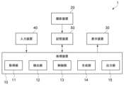
図1は、実施形態に係る処理システムの構成を示す模式図である。
実施形態に係る処理システム1は、処理装置10、撮影装置20、表示装置30、入力装置40、及び記憶装置50を含む。
FIG. 1 is a schematic diagram showing the configuration of a processing system according to an embodiment.
The
処理装置10は、仮想オブジェクトの生成に関する各種処理を実行する。例えば、処理装置10は、画像に写る人の手の検出、コマンドの検出、オブジェクトの生成、オブジェクトの保存などを実行する。処理装置10は、中央演算処理装置(CPU)、プログラムを保存又は実行するためのメモリ、各種インタフェースなどを含む。
The
撮影装置20は、人(ユーザ)の身体の一部や周囲の様子などを撮影する。撮影装置20は、画像を連続的に取得し、記憶装置50に保存する。撮影装置20は、例えば、RGB画像を取得可能なカメラを含む。カメラは、RGB画像に加えて、深度情報を取得できることがより好ましい。表示装置30は、ユーザに向けて、現実世界とは異なる仮想空間を表示する。表示装置30は、モニタ又はプロジェクタを含む。
The
入力装置40は、ユーザが処理装置10にデータを入力するために用いられる。入力装置40は、マイクを含む。マウス、キーボード、タッチパッドなどが入力装置40として用いられても良い。入力装置40の他に、ハンドジェスチャー、仮想の入力デバイスなどを用いて、処理装置10にデータが入力されても良い。
The
記憶装置50は、処理装置10の処理に必要なデータ、処理装置10の処理によって得られたデータなどを記憶する。記憶装置50は、例えば、Hard Disk Drive(HDD)及びSolid State Drive(SSD)から選択される1つ以上を含む。
The
処理装置10は、撮影装置20、表示装置30、入力装置40、及び記憶装置50と電気的に接続される。処理装置10は、撮影装置20、表示装置30、入力装置40、及び記憶装置50と、有線通信又は無線通信で接続されても良い。記憶装置50としてネットワークHDD(NAS)などが用いられ、処理装置10と記憶装置50がネットワークを介して接続されても良い。
The
処理装置10は、具体的には、図1に示すように、取得部11、検出部12、制御部13、生成部14、及び出力部15としての機能を備える。取得部11は、撮影装置20によって取得された画像、入力装置40によって入力されたデータなどをリアルタイムで取得する。
Specifically, as shown in FIG. 1, the
検出部12は、画像に写るユーザの手を検出する。検出部12は、検出した手の各点の三次元的な位置を計測する。具体的には、手は、DIP関節、PIP関節、MP関節、CM関節など、複数の関節を含む。これらのいずれかの関節の位置が、手の位置として用いられる。複数の関節の重心位置が、手の位置として用いられても良い。又は、手の全体の中心位置が、手の位置として用いられても良い。
The
検出部12は、連続的に取得された画像に対して手の検出を繰り返し、ハンドトラッキングを実行する。また、検出部12は、検出された手の位置の時系列的な変化から、ハンドジェスチャーを検出する。例えば、検出部12は、手の位置の変化と、予め定義されたそれぞれのハンドジェスチャーの手の動きと、の間の類似度を算出する。いずれかのハンドジェスチャーについて、類似度が予め設定された閾値を超えた場合、検出部12は、ユーザの手の動きがそのハンドジェスチャーを示していると判断する。
The
取得部11によって音声のデータが取得される場合、検出部12は、音声から音声コマンドを検出する。例えば、検出部12は、音声認識を実行し、ユーザの発話内容を文字列に変換する。検出部12は、発話内容が予め定義されたいずれかの音声コマンドの文字列を含むか判断する。発話内容がいずれかの音声コマンドの文字列を含む場合、検出部12は、ユーザがその音声コマンドを発話していると判断する。
When voice data is acquired by the
ハンドジェスチャー及び音声コマンドは、それぞれコマンドの一種である。複数のコマンドと、各コマンドの機能と、が定義された定義ファイルが予め準備される。制御部13は、検出されたコマンド(ハンドジェスチャー又は音声コマンド)に対応する機能を実行させるように、生成部14に指示を送信する。
Hand gestures and voice commands are each a type of command. A definition file is prepared in advance in which multiple commands and the functions of each command are defined. The
生成部14は、指示に応じて、仮想的なオブジェクトを生成したり、オブジェクトの位置、サイズ、形状などを変更したりする。出力部15は、生成又は変更されたオブジェクトを含む仮想空間の映像信号を、表示装置30へ出力する。表示装置30は、入力された映像信号に基づいて、仮想空間を表示する。
The
以下で、具体例を参照して、本発明の実施形態の詳細を説明する。ここでは、処理システム1が、MRデバイスとして実施される例を説明する。MRデバイスでは、仮想空間が現実空間と重ねて表示される。ユーザは、仮想空間に表示されたオブジェクトに干渉することができる。
Below, the details of an embodiment of the present invention will be described with reference to a specific example. Here, an example will be described in which the
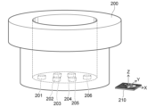
図2は、実施形態に係る複合現実デバイスを例示する模式図である。
図1に示す処理システム1は、例えば図2に示すMRデバイス100として実施される。MRデバイス100は、フレーム101、レンズ111、レンズ112、投影装置121、投影装置122、画像カメラ131、深度カメラ132、センサ140、マイク141、処理装置150、バッテリ160、及び記憶装置170を含む。
FIG. 2 is a schematic diagram illustrating a mixed reality device according to an embodiment.
The
処理装置150は、処理装置10の一例である。投影装置121及び投影装置122は、表示装置30の一例である。画像カメラ131及び深度カメラ132は、撮影装置20の一例である。マイク141は、入力装置40の一例である。記憶装置170は、記憶装置50の一例である。
The
図示した例では、MRデバイス100は、2眼式の頭部装着ディスプレイである。フレーム101には、2つのレンズ111及びレンズ112が嵌め込まれている。投影装置121及び投影装置122は、それぞれ、レンズ111及びレンズ112に情報を投影する。
In the illustrated example, the
投影装置121及び投影装置122は、レンズ111及びレンズ112に、ユーザの身体の検出結果、仮想のオブジェクトなどを表示する。ユーザは、MRデバイス100の装着者である。投影装置121及び投影装置122の一方のみが設けられ、レンズ111及びレンズ112の一方にのみ情報が表示されても良い。
レンズ111及びレンズ112は、光透過性を有する。ユーザは、レンズ111及びレンズ112を通して、現実の様子を視認できる。また、ユーザは、投影装置121及び投影装置122によってレンズ111及びレンズ112に投影された情報も視認できる。投影装置121及び投影装置122による投影により、情報が現実空間に重ねて表示される。
画像カメラ131は、可視光を検出し、二次元の画像を得る。深度カメラ132は、赤外光を照射し、反射された赤外光に基づいて深度画像を得る。センサ140は、6軸検出センサであり、3軸の角速度及び3軸の加速度を検出可能である。マイク141は、音声入力を受け付ける。
The
処理装置150は、MRデバイス100の各要素を制御する。例えば、処理装置150は、投影装置121及び投影装置122による表示を制御する。処理装置150は、センサ140による検出結果に基づいて、視界の移動を検出する。処理装置150は、視界の移動に応じて、投影装置121及び投影装置122による表示を変化させる。その他、処理装置150は、画像カメラ131及び深度カメラ132から得られたデータ、記憶装置170のデータなどを用いて、各種処理を実行可能である。
The
バッテリ160は、動作に必要な電力をMRデバイス100の各要素に供給する。記憶装置170は、処理装置150の処理に必要なデータ、処理装置150の処理によって得られたデータなどを保存する。記憶装置170は、MRデバイス100の外部に設けられ、処理装置150と通信しても良い。
The
図示した例に限らず、実施形態に係るMRデバイスは、一眼式の頭部装着ディスプレイであっても良い。MRデバイスは、図示したようなメガネ型であっても良いし、ヘルメット型であっても良い。 The MR device according to the embodiment is not limited to the illustrated example, and may be a single-lens head-mounted display. The MR device may be of the glasses type as illustrated, or of the helmet type.
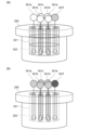
図3は、現実空間の様子を示す模式図である。
現実空間に、図3に示す物品200が存在する。物品200は、筒状の部材である。物品200の内側は空洞であり、空洞の底に締結箇所201~206が存在する。この例では、物品200に対して、ねじの締結作業が行われる。締結作業では、レンチ及びエクステンションバーを用いて、締結箇所201~206のそれぞれにねじが締結される。締結作業時に、MRデバイスは、この作業を支援するために用いられる。例えば、仮想的なオブジェクトによって、工具の適切な姿勢、締結位置、締結の際の手が配される位置、などが示される。
FIG. 3 is a schematic diagram showing the state of real space.
An
作業対象である物品200の近くには、マーカ210が設けられる。図示した例では、マーカ210は、ARマーカである。後述するように、マーカ210は、三次元座標系の基点を設定するために設けられる。ARマーカの代わりに、一次元コード(バーコード)、二次元コード(QRコード(登録商標))などがマーカ210として用いられても良い。又は、マーカの代わりに、基点がハンドジェスチャーによって示されても良い。処理装置150は、ハンドジェスチャーによって示された複数の点を基準に、仮想空間の三次元座標系を設定する。
A
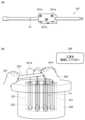
図4は、作業時の様子を示す模式図である。
物品200にねじが締結される際、作業者は、いずれかの締結箇所にねじを配置する。作業者は、エクステンションバー251の一端をねじに嵌める。作業者は、エクステンションバー251の他端に、レンチ252を嵌める。図4に示すように、作業者は、両手で、レンチ252の両端をそれぞれ握る。この状態で、作業者は、レンチ252を回してエクステンションバー251を回転させることで、締結箇所にねじを締める。
FIG. 4 is a schematic diagram showing a state during work.
When a screw is fastened to the
ねじを用いた作業が実行される際、工具は、適切な姿勢で使用されることが好ましい。工具が不適切な姿勢で使用されると、物品を損傷させる可能性がある。作業者が怪我をする可能性もある。ここでは、作業者が工具を適切な姿勢で使用するように、仮想的な治具が設けられる例を説明する。 When performing work using screws, it is preferable that the tool is used in a proper posture. If the tool is used in an inappropriate posture, it may damage the item. There is also a possibility that the worker may be injured. Here, an example is described in which a virtual jig is provided to ensure that the worker uses the tool in a proper posture.
まず、オブジェクトを準備する際、マーカ210に対する物品200の位置が調整される。オブジェクトを準備するときの物品200とマーカ210との位置関係は、作業が実行されるときの物品200とマーカ210との位置関係と同じに調整される。これにより、作業の際に、準備したオブジェクトを、適切な位置で物品200と重ねて表示させることができる。
First, when preparing an object, the position of the
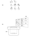
図5(a)~図5(c)、図6(a)~図6(c)、図7(a)~図7(c)、図8(a)~図8(c)、図9(a)~図9(c)、図10(a)、図10(b)、図11(a)~図11(c)、図12(a)、及び図12(b)は、本発明の実施形態を説明するための模式図である。
図を参照しながら、実施形態の具体例を説明する。まず、処理装置10は、ハンドトラッキングにより、ユーザの左手301及び右手302を検出する。ユーザは、MRデバイスの装着者である。図5(a)に示すように、ユーザは、オブジェクトを生成する位置を指で差す。このとき、指先の位置が、処理装置10によって計測される。次に、図5(b)に示すように、ユーザは、生成したいオブジェクトの形状を発話する。記憶装置50には、予め、形状が音声コマンドとして登録される。処理装置10は、発話311に含まれる音声コマンドを検出する。処理装置10は、図5(c)に示すように、音声コマンドに対応する形状のオブジェクト321を生成して表示する。
Figures 5(a) to 5(c), 6(a) to 6(c), 7(a) to 7(c), 8(a) to 8(c), 9(a) to 9(c), 10(a), 10(b), 11(a) to 11(c), 12(a), and 12(b) are schematic diagrams for explaining embodiments of the present invention.
A specific example of the embodiment will be described with reference to the drawings. First, the
次に、ユーザは、生成されたオブジェクト321の位置を調整する。まず、図6(a)に示すように、ユーザは、一方の手の指で、オブジェクト321の一部に触れる。ユーザは、もう一方の手の指で、オブジェクト321の当該一部の移動先を差す。ユーザの両手の指により、オブジェクト321の移動量及び移動方向が指定される。この状態で、図6(b)に示すように、ユーザは、オブジェクトを移動させるための音声コマンドを発話する。処理装置10は、指先の検出結果及び発話312に含まれる音声コマンドの検出結果に基づき、図6(c)に示すように、オブジェクト321を移動させる。なお、生成された位置からオブジェクト321を移動させる必要が無い場合、移動の処理は省略可能である。
Next, the user adjusts the position of the generated
次に、ユーザは、オブジェクト321のサイズを調整する。まず、図7(a)に示すように、ユーザは、両方の手の指で、オブジェクト321の幅を示す。図7(b)に示すように、ユーザは、調整したい寸法を発話313によって指定する。処理装置10は、図7(c)に示すように、指先の検出結果及び発話313に含まれる音声コマンドの検出結果に基づき、オブジェクト321の幅を変更する。図示した例では、円柱のオブジェクト321は、幅の変化に合わせて、奥行も変化するように設定されている。幅と奥行が、それぞれ個別に調整可能であっても良い。
Next, the user adjusts the size of the
幅が調整された後、図8(a)に示すように、ユーザは、両方の手の指で、オブジェクト321の高さを示す。ユーザは、図8(b)に示すように、調整したい寸法を発話314によって指定する。図8(c)に示すように、処理装置10は、指先の検出結果及び発話314に含まれる音声コマンドの検出結果に基づき、オブジェクト321の高さを変更する。
After the width has been adjusted, the user indicates the height of the
生成されたオブジェクトには、属性を付与することもできる。ユーザは、図9(a)に示すように、オブジェクトのうち属性を付与する範囲を、両手の指で示す。図示した例では、高さ方向において、左手301の指と右手302の指との間の範囲が示されている。ユーザは、図9(b)に示すように、付与する属性に対応した音声コマンドを発話する。処理装置10は、発話315に含まれる音声コマンドを検出する。図9(c)に示すように、処理装置10は、オブジェクト321のうち、両手の指で示された範囲321aに、「治具1段目」の属性を付与する。
Attributes can also be assigned to the generated object. As shown in FIG. 9(a), the user indicates the range of the object to which the attribute is to be assigned with the fingers of both hands. In the illustrated example, the range between the fingers of the
ユーザは、図9(a)~図9(c)に示す方法と同様の方法により、オブジェクト321にさらに属性を付与できる。例えば図10(a)に示すように、ユーザは、範囲321aの下方に位置する範囲321bを指で差す。ユーザは、発話316により、範囲321bに「治具2段目」の属性を付与する。図10(b)に示すように、ユーザは、範囲321bの下方に位置する範囲321cを指で差す。ユーザは、発話317により、範囲321cに「治具3段目」の属性を付与する。
The user can further assign attributes to object 321 in a manner similar to that shown in Figures 9(a) to 9(c). For example, as shown in Figure 10(a), the user points with his finger at
この例では、仮想的な「治具」は、作業時に、工具が進入してはいけない領域を表す。工具が誤った姿勢で使用されている場合に、工具と治具が接触するように、治具が配置される。実際の作業時に、処理装置10は、「治具」の属性が付与されたオブジェクトと、工具と、の間の距離を算出する。当該距離が所定の閾値を下回り、工具が治具に接触していると判断されると、処理装置10はアラートを発する。
In this example, the virtual "jig" represents an area where the tool must not enter during work. The jig is positioned so that the tool and jig will come into contact if the tool is used in an incorrect position. During actual work, the
また、工具が、誤った姿勢で物品200の空洞のより深くに挿入されるほど、処理装置10は、より強いアラートを発する。すなわち、治具1段目に工具が接触したときのアラートと、治具2段目に工具が接触したときのアラートと、治具3段目に工具が接触したときのアラートと、が互いに異なる。治具2段目に工具が接触したときのアラートは、治具1段目に工具が接触したときのアラートよりも強く、治具3段目に工具が接触したときのアラートよりも弱い。例えば、処理装置10は、工具が誤った姿勢でより深く挿入されるほど、より大きなメッセージ、より大きな警告音、又はより色の濃い警告色を発する。
In addition, the deeper the tool is inserted into the cavity of the
オブジェクト321の形状が加工されても良い。例えば、ユーザは、エクステンションバー251を通すための孔をオブジェクト321に形成する。まず、図11(a)に示すように、ユーザは、孔を形成する位置を指で差す。図11(b)に示すように、ユーザは、孔を形成するための音声コマンドを発話する。処理装置10は、発話318に含まれる音声コマンドを検出する。図11(c)に示すように、処理装置10は、音声コマンドに応じて孔322をオブジェクト321に形成する。
The shape of the
孔322のサイズを調整する場合、ユーザは、指又は音声コマンドによって孔322を選択する。図6(a)~図8(c)に示す方法と同様の方法により、ユーザは、孔322の位置、幅、奥行、高さを調整できる。
To adjust the size of
オブジェクトの形状、位置、サイズ、属性が設定されると、ユーザは、生成したオブジェクトを保存する。例えば、ユーザは、オブジェクトを指で差し、保存のための音声コマンドを発話する。処理装置10は、その発話に含まれる音声コマンドを検出し、指で差されたオブジェクトのデータを保存する。
Once the object's shape, position, size, and attributes have been set, the user saves the generated object. For example, the user points at the object with his or her finger and speaks a voice command to save it. The
オブジェクトを生成又は変更するためのコマンドとして、音声以外に、図12(a)に示すように、種々のハンドジェスチャーが用いられても良い。又は、図12(b)に示すように、仮想の入力デバイスであるパネル325が表示されても良い。ユーザは、パネル325に表示されたコマンドを選択(タッチ)する。処理装置10は、ハンドトラッキングにより、選択されたコマンドを検出する。処理装置10は、そのコマンドに応じた処理を実行する。
In addition to voice, various hand gestures may be used as commands for generating or modifying an object, as shown in FIG. 12(a). Alternatively, as shown in FIG. 12(b), a
オブジェクトの位置、サイズ、属性の設定の順序は、適宜変更可能である。位置又はサイズの調整が不要である場合、又は属性の設定が不要である場合は、それらのステップが省略されても良い。 The order in which the object's position, size, and attributes are set can be changed as appropriate. If adjustment of the position or size is not required, or if attribute setting is not required, those steps may be omitted.
上述したように、処理装置10は、ユーザによるコマンドの入力に応じて、仮想空間にオブジェクトを生成することができる。また、コマンド及び手の動きに応じて、オブジェクトの位置及びサイズを適宜調整可能である。さらに、処理装置10は、オブジェクトへの属性の設定を受け付け可能である。処理装置10は、各オブジェクトを特定するためのIDに、位置、サイズ、及び属性を紐付けて保存する。
As described above, the
図13(a)~図13(c)、図14(a)~図14(c)、図15(a)、図15(b)、図16(a)~図16(c)、図17(a)~図17(c)、図18、図19(a)、及び図19(b)は、本発明の実施形態を説明するための模式図である。
図5(a)~図11(c)では、工具が進入してはいけない領域を示すためのオブジェクトが生成される例を説明した。図13(a)以降では、作業時に、手が配される位置を示すためのオブジェクトが生成される例を説明する。
Figures 13(a) to 13(c), 14(a) to 14(c), 15(a), 15(b), 16(a) to 16(c), 17(a) to 17(c), 18, 19(a), and 19(b) are schematic diagrams for explaining embodiments of the present invention.
5(a) to 11(c) have been described as examples in which an object is generated to indicate an area where a tool must not enter. From Fig. 13(a) onwards, an example is described in which an object is generated to indicate a position where a hand is placed during work.
まず、図13(a)に示すように、ユーザは、オブジェクトを生成する位置を、一方の手の指で差す。ユーザは、オブジェクトの一部の位置を設定するための音声コマンドを発話する。処理装置10は、発話331に含まれる音声コマンドを検出する。処理装置10は、指先の位置を計測し、その位置を取得する。次に、図13(b)に示すように、ユーザは、他方の手の指で、オブジェクトの別の一部の位置を差し、オブジェクトを生成するための音声コマンドを発話する。処理装置10は、発話332に含まれる音声コマンドを検出し、図13(c)に示すように、オブジェクト341aを生成する。
First, as shown in FIG. 13(a), the user points with a finger of one hand to the position where an object is to be generated. The user utters a voice command to set the position of a part of the object. The
図示した例では、前記一方の手は、左手301である。前記他方の手は、右手302である。この例では、左手301の指の位置がベクトルの始点として認識され、右手302の指の位置がベクトルの終点として認識されるように、予め設定されている。ベクトルの始点と終点に、予め設定された形状のオブジェクトがそれぞれ生成される。
In the illustrated example, the one hand is a
ユーザは、オブジェクト321と同様に、オブジェクト341aの位置及びサイズを調整できる。図14(a)に示すように、ユーザは、発話333及び指の動きにより、オブジェクト341aを平行に移動できても良い。又は、図14(b)に示すように、ユーザは、発話334及び指差しにより、移動のための回転軸AXを設定できても良い。図14(c)に示すように、ユーザは、発話335及び指の動きにより、回転軸AXまわりにオブジェクト341aを移動できる。
The user can adjust the position and size of
次に、ユーザは、図15(a)に示すように、オブジェクト341aに指で触れる。図15(b)に示すように、発話336により、オブジェクト341aへ属性を付与する。この例では、オブジェクト341aは、作業時に手が配されるべき位置に設けられている。従って、作業が適切に実行されていると、オブジェクト341aに手が接触する。ユーザは、発話336の「ガイドボール」により、オブジェクト341aに手が触れたことを検出する機能を、オブジェクト341aに付与している。実際の作業時に、処理装置10は、手とオブジェクト341aとの間の距離を算出する。当該距離が所定の閾値を下回ると、処理装置10は、手がオブジェクト341aに接触していると判断する。手の代わりに、工具がオブジェクト341aに接触したことを検出する機能が、オブジェクト341aに付与されても良い。
Next, the user touches
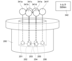
次に、図16(a)に示すように、ユーザは、別のオブジェクトを生成する位置を、一方の手の指で示す。ユーザは、オブジェクトの向きを、他方の手の指で示す。図16(b)に示すように、ユーザは、オブジェクトを生成するための音声コマンドを発話する。処理装置10は、発話337に含まれる音声コマンドを検出し、図16(c)に示すように、オブジェクト342を生成する。オブジェクト342は、作業時に、その作業に関するデータを表示する。左手301及び右手302により、データを表示するオブジェクト342の向きを指定できる。
Next, as shown in FIG. 16(a), the user indicates with the fingers of one hand the position at which another object should be generated. The user indicates with the fingers of the other hand the orientation of the object. As shown in FIG. 16(b), the user speaks a voice command to generate an object. The
ユーザは、図17(a)に示すように、オブジェクト342に指で触れる。ユーザは、図17(b)に示すように、オブジェクト342に表示させたいデータを発話338で示す。処理装置10は、発話338に含まれる音声コマンド及び内容を検出し、図17(c)に示すように、オブジェクト342にデータを表示させる。
The user touches
その後、オブジェクト341aと同様のオブジェクトの生成を繰り返すことで、図18に示すように、物品200の複数の締結箇所201~206にそれぞれ対応して、オブジェクト341a~341fが設定される。又は、オブジェクト341aをコピーするためのコマンドが準備されても良い。例えば、ユーザは、コピーのコマンドにより、既に生成されたオブジェクトと同一のオブジェクトを複製できる。
After that, by repeatedly generating objects similar to
オブジェクトの始点から終点、又はオブジェクトの向きは、両手の指の他、図19(a)に例示したように、手の平の向きなどで示されても良い。図示した例では、オブジェクトの向きが、手の甲から手の平の向きに設定される。 The start point to end point of an object, or the orientation of an object, may be indicated by the fingers of both hands, or by the orientation of the palm of the hand, as shown in FIG. 19(a). In the illustrated example, the orientation of the object is set to the orientation from the back of the hand to the palm.
図19(b)に示すように、複数のオブジェクトの配置を揃えるためのコマンドが準備されても良い。図示した例では、発話339により、複数のオブジェクトの上端が、指で差されたオブジェクト341aの上端の位置に揃えられている。図示した例の他、下端、左端、右端、手前側端部、又は奥側端部で、複数のオブジェクトを揃えることも可能である。上下方向における中央揃え、左右方向における中央揃え、又は奥行方向における中央揃えなどが実行されても良い。
As shown in FIG. 19(b), a command for aligning multiple objects may be prepared. In the illustrated example,
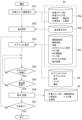
図20及び図21は、実施形態に係る処理方法を例示するフローチャートである。
図20は、オブジェクトの生成方法を示す。まず、処理装置10は、ハンドトラッキングを実行し、指先の三次元位置を取得する(ステップS11)。処理装置10は、記憶装置50に保存されたコマンドマスタ51を参照する。コマンドマスタ51には、各コマンドのID、各コマンドの名称、及び各コマンドの機能が登録されている。処理装置10は、コマンドマスタ51に登録されたコマンドと、ユーザからの入力(手の動き又は音声)と、を対比することで、コマンドを検出する。処理装置10は、オブジェクトを生成するためのコマンドを検出すると、オブジェクトを生成する(ステップS12)。
20 and 21 are flow charts illustrating a processing method according to an embodiment.
20 shows a method for generating an object. First, the
処理装置10は、オブジェクトのサイズを変更するためのコマンドを検出すると、オブジェクトのサイズを変更する(ステップS13)。処理装置10は、オブジェクトに属性を付与するためのコマンドを検出すると、オブジェクトに属性を付与する(ステップS14)。処理装置10は、オブジェクトを加工するためのコマンドを検出すると、オブジェクトを加工する(ステップS15)。
When the
オブジェクトの生成、サイズの変更、及び属性の付与が完了すると、ユーザは、オブジェクトを保存するためのコマンドを発話する。処理装置10は、そのコマンドを検出すると、生成されたオブジェクトを保存する(ステップS16)。オブジェクトは、記憶装置50のオブジェクトマスタ52に保存される。オブジェクトマスタ52には、各オブジェクトのID、各オブジェクトの形状、サイズ、属性などが登録される。
When the object has been created, its size changed, and its attributes added, the user speaks a command to save the object. When the
処理装置10は、オブジェクトの生成が継続されるか判断する(ステップS17)。例えば、オブジェクトの生成の終了を示すコマンドを受け付けるまで、処理装置10は、オブジェクトの生成を継続する。生成されるオブジェクトの数などの終了条件が予め定められていても良い。処理装置10は、終了条件が満たされると、オブジェクトの生成を終了する。オブジェクトの生成が継続される場合、ステップS12が再度実行される。
The
ステップS12~S15の順序は、適宜変更可能である。ステップS11とステップS16との間で、オブジェクトの位置が調整されても良い。この例では、オブジェクトの最終的な表示位置は、後述するオブジェクトと作業ステップとの紐付において決定される。 The order of steps S12 to S15 can be changed as appropriate. The position of the object may be adjusted between steps S11 and S16. In this example, the final display position of the object is determined by linking the object to the task step, which will be described later.
図21は、オブジェクトの配置方法及び作業との紐付方法を示す。オブジェクトが生成されると、実際の作業時にオブジェクトが物品に合わせて表示されるように、各オブジェクトが配置され、作業と紐付けられる。 Figure 21 shows how to arrange objects and link them to tasks. Once the objects are generated, they are arranged and linked to tasks so that they are displayed in line with the items during the actual tasks.
まず、処理装置10は、ハンドトラッキングを実行し、指先の三次元位置を取得する(ステップS21)。次に、処理装置10は、画像に写るマーカを検出し、マーカを基準に三次元座標系の基点を設定する(ステップS22)。処理装置10は、オブジェクトと紐付される作業ステップの選択を受け付け、作業マスタ53から選択された作業ステップを読み込む(ステップS23)。
First, the
例えば、物品を作製する際、複数の工程が実行される。1つの工程は、1つ以上の作業ステップからなる。1つの作業ステップにおいて、締結作業が実行されうる。作業マスタ53は、作業ステップに関するデータを含み、記憶装置50に保存される。作業マスタ53は、各作業ステップのID、各作業ステップの名称、各作業ステップで作業される対象のID、作業される対象の物品名などを含む。ある作業ステップでねじが締結される場合、各締結箇所のID、各締結箇所の位置、使用される工具のデータ、目標のトルク値なども、作業マスタ53に保存される。
For example, when manufacturing an item, multiple processes are performed. One process consists of one or more work steps. In one work step, fastening work can be performed. The
作業ステップは、ユーザによって選択される。基点を設定するためのマーカに、作業ステップが紐付けられていても良い。その場合、処理装置10は、マーカと紐付けられた作業ステップを読み込む。
The work step is selected by the user. A work step may be linked to a marker for setting a base point. In that case, the
処理装置10は、紐付けられるオブジェクトの選択を受け付け、オブジェクトマスタ52から選択されたオブジェクトを読み込む(ステップS24)。処理装置10は、読み込んだオブジェクトを表示する(ステップS25)。処理装置10は、ユーザからのコマンドの入力を受け付け、コマンドに応じてオブジェクトを移動させる(ステップS26)。このとき、オブジェクトのサイズ、向きなどが調整されても良い。処理装置10は、移動後のオブジェクトの位置をオブジェクトマスタ52に保存する。また、処理装置10は、そのオブジェクトのデータを、オブジェクトマスタ52に保存するとともに、読み込んだ作業ステップのデータと紐付ける(ステップS27)。
The
配置されるオブジェクトが締結箇所と紐付けられる場合、ステップS23において、締結箇所がさらに選択される。処理装置10は、選択された締結箇所のIDに、配置されたオブジェクトのデータを紐付け、作業マスタ53に保存する。
If the object to be placed is linked to a fastening point, the fastening point is further selected in step S23. The
処理装置10は、オブジェクトの配置が継続されるか判断する(ステップS28)。例えば、オブジェクトの配置の終了を示すコマンドを受け付けるまで、処理装置10は、オブジェクトの配置を継続する。終了条件が予め定められていても良い。処理装置10は、終了条件が満たされると、オブジェクトの配置を終了する。オブジェクトの配置が継続される場合、ステップS24が再度実行される。
The
以上の処理により、オブジェクトの生成、オブジェクトの配置、オブジェクトの作業ステップとの紐付が完了する。準備されたオブジェクトは、実際の作業時、作業者に向けて表示される。作業者は、オブジェクトが表示されることで、より円滑に作業を実行できる。 Through the above process, the creation of objects, their placement, and their association with work steps are completed. The prepared objects are displayed to the worker when actually working. The worker can carry out the work more smoothly by seeing the objects displayed.
実施形態の利点を説明する。
XRデバイスに仮想のオブジェクトが表示されることで、様々な方法で作業を支援することができる。仮想空間におけるオブジェクトは、通常、PC上で専用のソフトウェアを用いて生成される。このため、ソフトウェアに関する専門的な知識の乏しい人には、オブジェクトの設定が困難である。例えば、どの位置にどのようなオブジェクトが表示されると作業し易いか、作業者であれば容易に推察できる。しかし、一般の作業者は、仮想空間に関するソフトウェアの扱いに慣れておらず、オブジェクトを設定することが困難である。
Advantages of the embodiment will be described.
Displaying virtual objects on an XR device can assist with work in various ways. Objects in a virtual space are usually generated using dedicated software on a PC. For this reason, it is difficult for people with little specialized knowledge of software to set objects. For example, a worker can easily guess what kind of object should be displayed at what position to make work easier. However, general workers are not familiar with handling software related to virtual spaces and have difficulty setting objects.
この課題について、本発明の実施形態によれば、XRデバイスを用いて、仮想のオブジェクトを生成することができる。具体的には、処理装置10は、撮影装置20によって取得された画像から、人の手を検出する。処理装置10は、ハンドジェスチャー又は音声コマンドなどに基づいて、仮想空間に仮想のオブジェクトを生成する。換言すると、XRデバイスを装着した人は、ハンドジェスチャー又は音声コマンドを入力するだけで、処理装置10にオブジェクトを生成させることができる。また、処理装置10は、ハンドトラッキングによって人の手の動きを検出し、手の動きに応じてオブジェクトの位置及びサイズを変更する。人は、位置及びサイズを変更するためのコマンドを入力しながら手を動かすことで、オブジェクトの位置及びサイズを調整できる。
Regarding this problem, according to an embodiment of the present invention, a virtual object can be generated using an XR device. Specifically, the
実施形態によれば、予め準備されたコマンドと手の動きによって、オブジェクトの生成、位置の調整、及びサイズの調整を実行できる。このため、専門的な知識の乏しい人でも、容易に仮想のオブジェクトを準備できる。 According to the embodiment, object generation, position adjustment, and size adjustment can be performed using pre-prepared commands and hand movements. This allows even people with little specialized knowledge to easily prepare virtual objects.
具体的な一例として、作業については、一般的に、作業の手順が定義された作業マスタ53が予め準備される。ハンドジェスチャー、音声コマンドなどが定義されたコマンドマスタを準備すれば、作業マスタ53を利用して本発明の実施形態を実施できる。例えば、作業に係る作業者又はその管理者が、作業を支援するためのオブジェクトを準備する。準備されたオブジェクトを、作業マスタ53のデータと適宜紐付けることで、実際の作業時に準備されたオブジェクトを表示させることができる。
As a specific example, for work, a
現実空間における作業を支援するためにオブジェクトが準備される場合、オブジェクトの位置、向きなどを、現実空間の物品に合わせる必要がある。すなわち、オブジェクトが準備されるときの仮想空間の三次元座標系は、作業が実行されるときの仮想空間の三次元座標系と同じに設定される。また、オブジェクトが準備されるときの三次元座標系の基点と作業対象との位置関係は、作業が実行されるときの三次元座標系の基点と作業対象との位置関係と同じに設定される。 When an object is prepared to assist with work in real space, the position, orientation, etc. of the object must be aligned with the item in real space. In other words, the three-dimensional coordinate system of the virtual space when the object is prepared is set to be the same as the three-dimensional coordinate system of the virtual space when the work is performed. In addition, the positional relationship between the base point of the three-dimensional coordinate system when the object is prepared and the work target is set to be the same as the positional relationship between the base point of the three-dimensional coordinate system and the work target when the work is performed.
これらの設定を容易にするために、図3に示すように、基点を設定するためのマーカ210が現実空間に準備されることが好ましい。オブジェクトが準備される際、処理装置10は、画像からマーカ210を検出すると、マーカ210を基点として三次元座標系を設定する。作業が実行される際も、処理装置10は、画像からマーカ210を検出し、マーカ210を基点として三次元座標系を設定する。マーカ210と作業される物品との位置関係が変化しなければ、作業時に、準備されたオブジェクトを、物品に合わせて表示することができる。
To facilitate these settings, it is preferable that a
オブジェクトには、そのオブジェクトの機能を示す属性を設定することもできる。上述した例では、所定の物体がオブジェクトへ接触したことを検出する機能が、属性として付与されている。「治具」の属性がオブジェクトに付与される場合、オブジェクトに工具が接触すると、処理装置10は、アラートを出力する。「ガイドボール」の属性がオブジェクトに付与される場合、オブジェクトに手又は工具が接触すると、処理装置10は、対応する締結箇所に対してねじが回されていると推定する。
An object can also be set with an attribute that indicates the function of the object. In the above example, the attribute is given the function of detecting when a specific object comes into contact with the object. If the attribute of "jig" is given to an object, the
オブジェクトは、特に、締結箇所に対応して表示されることが好ましい。大型の物品が作製される場合、締結箇所の数が多く、全ての締結箇所を作業者が把握することが困難となりうる。また、図3に示すように、一部の締結箇所が視認し難い位置に存在する場合、ねじの締め忘れが生じうる。 It is particularly preferable that the objects are displayed corresponding to the fastening points. When a large item is produced, there are a large number of fastening points, and it may be difficult for the worker to identify all of the fastening points. In addition, as shown in Figure 3, if some fastening points are located in places that are difficult to see, it may happen that screws are left untightened.
締結箇所に対応してオブジェクトが表示される場合、締結箇所に関するデータとオブジェクトとが紐付けられることが好ましい。また、オブジェクトには、手又は工具が接触したことを検出する機能(属性)が付与されることが好ましい。この方法によれば、オブジェクトに手又は工具が接触している場合に、そのオブジェクトに対応する締結箇所に対してねじが回されていると推定できる。この推定結果に基づき、処理装置10は、どの締結箇所にねじが回されたかを示す作業記録を自動的に作成しても良い。
When an object is displayed corresponding to a fastening point, it is preferable that data regarding the fastening point is linked to the object. It is also preferable that the object is given a function (attribute) for detecting contact with a hand or a tool. According to this method, when a hand or a tool is in contact with an object, it can be estimated that a screw is being turned into the fastening point corresponding to the object. Based on the result of this estimation, the
図22(a)、図22(b)、図23、図24(a)、図24(b)、図25(a)、及び図25(b)は、作業時の様子を示す模式図である。
締結作業が実行される際、作業ステップが選択され、処理装置10に入力される。処理装置10は、入力された作業ステップのデータを作業マスタ53から読み込む。処理装置10は、その作業ステップに紐付けられたオブジェクトを読み込む。
22(a), 22(b), 23, 24(a), 24(b), 25(a) and 25(b) are schematic diagrams showing the state during work.
When a fastening operation is to be performed, a work step is selected and input to the
図3に示す物品200にねじが締結される際、図22(a)に示すように、オブジェクト321、オブジェクト341a~341f、及びオブジェクト342が読み込まれる。処理装置10は、図22(b)に示すように、仮想空間のオブジェクト321、オブジェクト341a~341f、及びオブジェクト342を、現実空間の物品200と重ねて表示する。
When a screw is fastened to the
図22(b)では不図示の締結箇所201~206は、物品200の空洞の底に位置する。作業者は、締結箇所201~206を視認し難い。オブジェクト341a~341fは、締結箇所201~206にそれぞれねじが締結される際、手が配されるべき位置に表示される。オブジェクト341a~341fが表示されることで、作業者は、作業時に、どこに手を位置させれば良いか、容易に把握できる。
The fastening points 201-206, not shown in FIG. 22(b), are located at the bottom of the cavity of the
また、オブジェクト341a~341fのそれぞれは、締結箇所から離れた球状の部分と、当該球状部分と締結箇所とを結ぶ線状の部分と、を含む。線状の部分は、球状の部分に手が位置する場合の工具の適切な位置及び姿勢を示している。図示したように、手が配されるべき位置、工具の位置、及び工具の姿勢が示されることで、作業者が、より円滑に作業を実行できる。
Each of the
オブジェクト341a~341fのいずれかに手が接触すると、処理装置10は、その接触を検出する。図23に示す例では、オブジェクト341fに手が接触している。処理装置10は、オブジェクト341fに対応する締結箇所にねじが締結されていると推定できる。ここでは、オブジェクトへの接触によってねじが締結されていると推定された締結箇所を、「推定箇所」と呼ぶ。
When a hand comes into contact with any of
好ましくは、作業では、デジタル工具が用いられる。処理装置10は、デジタル工具から検出値を受信する。処理装置10は、検出値を用いて、推定箇所へのねじ締めが完了したか判断できる。ねじ締めが完了したと判断されると、処理装置10は、作業記録に作業結果を入力する。この方法によれば、より正確な作業記録を自動的に作成することが可能となる。
Preferably, a digital tool is used in the work. The
例えば、デジタル工具はデジタルトルクレンチ又はデジタルトルクドライバであり、検出値は、デジタルトルクレンチ又はデジタルトルクドライバによって検出されたトルク値である。デジタルトルクレンチ又はデジタルトルクドライバは、トルク値を検出し、処理装置10へ送信する。処理装置10は、トルク値が所定の閾値を超えている場合、ねじ締めが完了したと判断する。デジタルトルクレンチ又はデジタルトルクドライバが、所定の閾値を超えるトルクが検出されたか否かを判定しても良い。その場合、デジタルトルクレンチ又はデジタルトルクドライバは、トルク値の代わりに、その判定結果を検出値として出力しても良い。デジタルトルクレンチ又はデジタルトルクドライバは、判定結果とトルク値の両方を出力しても良い。処理装置10は、推定箇所に関するデータに、受信した検出値を紐付けても良い。
For example, the digital tool is a digital torque wrench or digital torque driver, and the detection value is a torque value detected by the digital torque wrench or digital torque driver. The digital torque wrench or digital torque driver detects the torque value and transmits it to the
所定の物体の接触に応じて、オブジェクトの表示態様の変化、メッセージの出力、又は音声の出力が実行されるように、オブジェクトに属性が付与されても良い。例えば、処理装置10は、オブジェクト341fの表示態様を変化させる。手が接触したオブジェクト341fの表示態様は、手が接触していないオブジェクト341fの表示態様と異なる。図示した例では、オブジェクト341fの色が変化している。オブジェクト341fの大きさ又は形状が変化しても良い。オブジェクト341fへの手の接触が、メッセージ又は音声で通知されても良い。これにより、ユーザは、仮想オブジェクトに所定の物体が接触しているか否か、容易に判断できる。
Attributes may be assigned to the object so that the display mode of the object is changed, a message is output, or sound is output in response to contact with a specific object. For example, the
1つの箇所にねじが締結され、別の箇所に別のねじが締結された後に、その1つの箇所のねじが締め直される場合がある。この場合、処理装置10は、ねじ締めの回数に応じて、オブジェクト341a~341fの表示態様を変化させても良い。図24(a)に示す例では、オブジェクト341fに対応する締結箇所にねじが締結されている。他のオブジェクト341a~341eに対応する締結箇所には、ねじが締結されていない。図24(b)に示す例では、オブジェクト341fに対応する締結箇所のねじが、締め直されている。他のオブジェクト341a~341eに対応する締結箇所のねじは、未だ締め直されていない。オブジェクト341fに対応する締結箇所へのねじ締め回数が、オブジェクト341a~341eに対応する締結箇所へのねじ締め回数と異なる。このため、オブジェクト341fの表示態様が、オブジェクト341a~341eの表示態様と異なっている。
There are cases where a screw is fastened at one location, another screw is fastened at another location, and then the screw at that one location is retightened. In this case, the
オブジェクト321には、治具の属性が付与されている。例えば図25(a)に示すように、エクステンションバー251に、複数のマーカ251aが取り付けられる。処理装置10は、画像から複数のマーカ251aを検出する。処理装置10は、各マーカ251aの位置を計測する。複数のマーカ251aと、エクステンションバー251と、の間の位置関係が予め登録される。この位置関係に基づき、処理装置10は、各マーカ251aの位置から、エクステンションバー251の位置P1を算出する。処理装置10は、エクステンションバー251の位置P1が、オブジェクト321の孔322以外の部分と重なると、エクステンションバー251がオブジェクト321に接触していると判断する。
The
オブジェクト341fと同様に、オブジェクト321にも、接触をユーザに示すための属性を付与できる。図25(b)に示す例では、処理装置10が、アラートとして、メッセージ326を表示する。処理装置10は、オブジェクト321の色、大きさ、形状などを変化させても良い。
As with
オブジェクトに属性が付与されることで、様々な方法で締結作業を支援することが可能となる。属性の具体的な機能については、コマンドマスタ51に登録される。1つの属性に、上述した種々の機能が登録されても良い。1つの属性に単一の機能のみが登録され、1つのオブジェクトに複数の属性が付与されても良い。
By assigning attributes to objects, it becomes possible to assist the fastening work in various ways. The specific functions of the attributes are registered in the
図26は、実施形態に係る処理方法を示すフローチャートである。
図26は、実際の作業時における処理の流れを示す。例えば、第1処理装置が、図20及び図21に示す処理を実行し、オブジェクトが準備される。その後、第2処理装置が、図26に示す処理を実行する。第2処理装置は、第1処理装置と同じでも良いし、第1処理装置とは異なっていても良い。すなわち、作業で使用されるMRデバイスは、オブジェクトを準備するときに使用されるMRデバイスと同じでも良いし、異なっていても良い。
FIG. 26 is a flowchart illustrating a processing method according to an embodiment.
Fig. 26 shows a flow of processing during actual work. For example, the first processing device executes the processing shown in Fig. 20 and Fig. 21 to prepare an object. Thereafter, the second processing device executes the processing shown in Fig. 26. The second processing device may be the same as the first processing device, or may be different from the first processing device. That is, the MR device used in the work may be the same as the MR device used when preparing the object, or may be different.
まず、処理装置10は、作業ステップの選択を受け付ける(ステップS31)。作業ステップは、作業者によって選択される。実行される作業ステップが上位のシステムによって指示され、処理装置10は指示による選択を受け付けても良い。撮影装置20又は他のセンサから得られたデータに基づき、処理装置10がこれから実行される作業ステップを判断し、処理装置10は判断結果に基づく選択を受け付けても良い。
First, the
処理装置10は、作業マスタ53を参照し、選択された作業ステップのデータを取得する。作業マスタ53は、作業ステップデータ53a、基点データ53b、及び締結箇所データ53cを含む。
The
作業ステップデータ53aには、作業ステップID、作業ステップ名、作業対象である物品のID、物品名、使用される工具型式、工具IDなどが保存されている。工具型式は、構造、外形、又は性能などによる工具の分類を示す。処理装置10は、作業ステップID、作業ステップ名、物品ID、又は物品名のいずれかを作業の選択として受け付け可能である。作業ステップの選択において候補が複数存在する場合、処理装置10は、いずれの候補を選択するか問い合わせを出力しても良い。
The
処理装置10は、基点データ53bを参照する。基点データ53bには、作業ごとの基点の設定方法が保存されている。処理装置10は、選択された作業での基点の設定方法を取得し、作業者による入力に基づいて基点を設定する(ステップS32)。基点の設定には、上述したように、マーカが用いられることが好ましい。
The
処理装置10は、締結箇所データ53cを参照する。締結箇所データ53cには、締結箇所IDが保存され、締結箇所IDごとに締結位置、角度、エクステンションバー型式、トルク値、ねじ締め回数、マーク色、オブジェクト形状、及び表示態様が保存されている。締結位置は、各締結箇所の位置を示す。角度は、各締結箇所にねじを締める際の工具又はエクステンションバーの角度を示す。エクステンションバー型式は、構造、外形、又は性能などによるエクステンションバーの分類を示す。トルク値は、各締結箇所をねじ締めする際に必要なトルクの大きさを示す。ねじ締め回数は、各締結箇所におけるねじ締め回数を示す。マーク色は、ねじ締めの完了を示すマークの色である。オブジェクト形状は、各締結箇所に対応して表示されるオブジェクトの形状を示す。表示態様は、表示される各オブジェクトの態様を示す。表示態様は、ねじ締め回数ごとに設定される。ねじ締め回数、オブジェクト形状、表示態様などは、オブジェクトを生成した際、コマンドにより、オブジェクトに対して属性として付与できる。
The
処理装置10は、設定された基点とオブジェクトマスタ52のデータに基づき、準備されたオブジェクトを表示させる(ステップS33)。処理装置10は、仮想オブジェクトに所定の物体が接触したか、判断を繰り返す(ステップS34)。これにより、「治具」のオブジェクトに対する工具の接触、「ガイドボール」のオブジェクトに対する手の接触などが検出される。
The
「ガイドボール」のオブジェクトへの手の接触が検出されると、処理装置10は、デジタル工具から検出値を受信したか判断する(ステップS35)。検出値が受信されない場合、処理装置10は、ステップS34を再び実行する。
When hand contact with the "guide ball" object is detected, the
「ガイドボール」のオブジェクトへ手が接触し、且つ検出値が受信された場合、処理装置10は、締結箇所に関するデータを検出値と紐付け、それらのデータを履歴データ54(作業記録)に記録する(ステップS36)。例えば、締結箇所IDにトルク値が紐付けられ、記録される。図示した例では、その他に、作業ステップID、工具ID、及び工具型式などが紐付けられている。
When a hand comes into contact with the "guide ball" object and a detection value is received, the
処理装置10は、ステップS31で選択された作業ステップが完了したか判断する(ステップS37)。作業が完了していない場合、ステップS33によるオブジェクトの表示が継続される。
The
以上では、実施形態に係る処理システム1が、MRデバイスとして実施される例を説明した。この例に限らず、実施形態に係る処理システム1は、VRデバイスとして実施されても良い。
The above describes an example in which the
一例として、仮想空間に、作業対象である物品のオブジェクトが生成される。そのオブジェクトに対して、上述した例のように、作業を支援するためのオブジェクトが生成される。VRデバイスのユーザは、これらのオブジェクトを含む仮想空間で、締結作業を体験することができる。 As one example, an object of the item to be worked on is generated in a virtual space. For that object, an object to assist in the work is generated, as in the example described above. A user of a VR device can experience fastening work in a virtual space that includes these objects.
例えば、図2に示すデバイスにおいて、光を透過しないレンズ111及びレンズ112が用いられる。レンズ111及びレンズ112には、仮想空間のみが写る。より没入感を高めるために、ゴーグル型又はヘルメット型のVRデバイスが用いられても良い。
For example, in the device shown in FIG. 2,
図27、図28(a)、図28(b)、及び図29は、本発明の実施形態を説明するための模式図である。
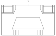
図27は、表示装置30に表示された仮想空間Vを示す。図示した例では、仮想の机や棚などが、仮想空間Vに表示されている。処理装置10は、ユーザの手を検出し、検出した手を仮想空間Vに表示させる。
27, 28(a), 28(b), and 29 are schematic diagrams for explaining an embodiment of the present invention.
27 shows a virtual space V displayed on the
図28(a)に示すように、ユーザは、仮想空間Vにおいてオブジェクトを生成する位置を指で差し、作業対象ID及び音声コマンドを発話する。この例では、作業対象IDが、音声コマンドとして予め登録されている。ユーザは、発話401によって、作業対象IDを指定している。 As shown in FIG. 28(a), the user points with his/her finger at the position in the virtual space V where an object is to be generated, and speaks the work object ID and a voice command. In this example, the work object ID is preregistered as a voice command. The user specifies the work object ID by speaking 401.
処理装置10は、発話401を検出し、作業マスタに保存された作業対象IDを参照する。図28(b)に示すように、処理装置10は、その作業対象IDを有する物品と同じサイズのオブジェクト411を仮想空間Vに生成する。その後、ユーザは、図6(a)~図8(c)に示す方法と同様の方法により、オブジェクト411の位置又はサイズを調整できる。さらに、オブジェクト411に属性が付与されても良い。
The
以降は、図5(a)~図11(c)に示す方法及び図13(a)~図17(c)に示す方法により、オブジェクト321、オブジェクト341a~341f、及びオブジェクト342を生成する。これにより、図29に示すように、締結作業をシミュレートするためのオブジェクトが仮想空間Vに準備される。
After that,
なお、VRデバイスが用いられる場合、作業対象のオブジェクトと作業を支援するためのオブジェクトが、同じ仮想空間上に生成される。このため、作業を支援するためのオブジェクトの位置やサイズなどを、現実空間の物品に合わせる必要が無い。このため、基点は任意に設定可能である。図3に示すように、マーカ210を用いる必要は無い。
When a VR device is used, the object to be worked on and the object to assist in the work are generated in the same virtual space. Therefore, there is no need to match the position or size of the object to assist in the work to an item in the real space. Therefore, the base point can be set arbitrarily. As shown in Figure 3, there is no need to use a
上述した例では、作業を支援するためにXRデバイスが用いられる例を説明した。本発明の実施形態は、作業以外の目的で仮想的なオブジェクトを生成する場合にも有効である。本発明の実施形態によれば、仮想空間に関する専門的な知識が乏しい人でも、仮想空間にオブジェクトを容易に生成することができる。 In the above example, an XR device is used to assist with work. The embodiment of the present invention is also effective in generating virtual objects for purposes other than work. According to the embodiment of the present invention, even people with little specialized knowledge of virtual spaces can easily generate objects in virtual spaces.
以上で説明した例では、締結箇所に対してねじが締められる例を主に説明した。本発明の実施形態は、締結箇所にねじが締められる場合だけでなく、締結箇所のねじを緩める場合にも適用可能である。例えば、製品の保守、点検、又は修理を行う場合に、締結箇所のねじが緩められる。例えば、ねじを緩める際に仮想のオブジェクトが表示されることで、作業者が、より円滑に作業を実行できる。 In the above examples, the description has been focused on examples in which a screw is tightened at a fastening point. The embodiments of the present invention are applicable not only to cases in which a screw is tightened at a fastening point, but also to cases in which a screw at a fastening point is loosened. For example, a screw at a fastening point is loosened when performing maintenance, inspection, or repair of a product. For example, by displaying a virtual object when loosening a screw, a worker can perform the work more smoothly.
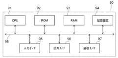
図30は、ハードウェア構成を示す模式図である。
処理装置10又は処理装置150として、例えば図30に示すコンピュータ90が用いられる。コンピュータ90は、CPU91、ROM92、RAM93、記憶装置94、入力インタフェース95、出力インタフェース96、及び通信インタフェース97を含む。
FIG. 30 is a schematic diagram showing a hardware configuration.
30 is used as the
ROM92は、コンピュータ90の動作を制御するプログラムを格納している。ROM92には、上述した各処理をコンピュータ90に実現させるために必要なプログラムが格納されている。RAM93は、ROM92に格納されたプログラムが展開される記憶領域として機能する。
The
CPU91は、処理回路を含む。CPU91は、RAM93をワークメモリとして、ROM92又は記憶装置94の少なくともいずれかに記憶されたプログラムを実行する。プログラムの実行中、CPU91は、システムバス98を介して各構成を制御し、種々の処理を実行する。
The
記憶装置94は、プログラムの実行に必要なデータや、プログラムの実行によって得られたデータを記憶する。記憶装置94は、Solid State Drive(SSD)などを含む。記憶装置94は、記憶装置50又は記憶装置170として用いられても良い。
The
入力インタフェース(I/F)95は、コンピュータ90を入力装置40と接続可能である。CPU91は、入力I/F95を介して、入力装置40から各種データを読み込むことができる。
The input interface (I/F) 95 can connect the
出力インタフェース(I/F)96は、コンピュータ90と出力装置とを接続可能である。CPU91は、出力I/F96を介して表示装置30にデータを送信し、表示装置30に情報を表示させることができる。
The output interface (I/F) 96 can connect the
通信インタフェース(I/F)97は、コンピュータ90外部の機器と、コンピュータ90と、を接続可能である。通信I/F97は、例えば、デジタル工具とコンピュータ90とをBluetooth(登録商標)通信により接続する。
The communication interface (I/F) 97 can connect the
処理装置10又は処理装置150によるデータ処理は、1つのコンピュータ90のみによって実行されても良い。データ処理の一部が、通信I/F97を介してサーバなどで実行されても良い。
Data processing by the
上記の種々のデータの処理は、コンピュータに実行させることのできるプログラムとして、磁気ディスク(フレキシブルディスク及びハードディスクなど)、光ディスク(CD-ROM、CD-R、CD-RW、DVD-ROM、DVD±R、DVD±RWなど)、半導体メモリ、又は、他の非一時的なコンピュータで読取可能な記録媒体(non-transitory computer-readable storage medium)に記録されても良い。 The above various data processing may be recorded as a program that can be executed by a computer on a magnetic disk (such as a flexible disk or hard disk), an optical disk (such as a CD-ROM, CD-R, CD-RW, DVD-ROM, DVD±R, DVD±RW), a semiconductor memory, or other non-transitory computer-readable storage medium.
例えば、記録媒体に記録された情報は、コンピュータ(または組み込みシステム)により読み出されることが可能である。記録媒体において、記録形式(記憶形式)は任意である。例えば、コンピュータは、記録媒体からプログラムを読み出し、このプログラムに基づいてプログラムに記述されている指示をCPUで実行させる。コンピュータにおいて、プログラムの取得(または読み出し)は、ネットワークを通じて行われても良い。 For example, information recorded on a recording medium can be read by a computer (or an embedded system). The recording medium may have any recording format (storage format). For example, the computer reads a program from the recording medium and causes the CPU to execute instructions described in the program based on the program. In the computer, the program may be acquired (or read) via a network.
また、処理システム1は、XRデバイス以外で実施されても良い。例えば、汎用のPCを用いて、処理システム1が実施される。その場合、表示装置30として、モニタが用いられる。入力装置40として、キーボード、マイク、タッチパッド、マイクなどが用いられる。撮影装置20は、ユーザから離れた位置で、ユーザを撮影する。ユーザは、表示装置30を確認しながら、入力装置40を用いて、処理装置10へコマンドを入力する。
The
本発明の実施形態は、以下の特徴を含む。
(特徴1)
画像を取得する撮影装置と、
仮想空間を表示する表示装置と、
前記画像から人の手を検出する処理装置と、を備え、
前記処理装置は、
前記人によるコマンドの入力に応じて前記仮想空間にオブジェクトを生成し、
前記手の動きに応じて、生成された前記オブジェクトの位置及びサイズを変更する、
クロスリアリティデバイス。
(特徴2)
前記処理装置は、前記撮影装置によって現実空間に存在するマーカが撮影されると、前記マーカを基準として前記仮想空間の三次元座標系を設定し、前記三次元座標系において前記オブジェクトの前記位置及び前記サイズを変更する、特徴1に記載のクロスリアリティデバイス。
(特徴3)
前記処理装置は、前記オブジェクトの機能を示す属性の設定を受け付け可能であり、
前記機能は、所定の物体の前記オブジェクトへの接触の検出である、特徴1又は2に記載のクロスリアリティデバイス。
(特徴4)
前記オブジェクトは、現実空間の物品の締結箇所に関するデータと紐付けて保存される、特徴1~3のいずれか1つに記載のクロスリアリティデバイス。
(特徴5)
前記コマンドは、音声又はハンドジェスチャーによって入力される、特徴1~4のいずれか1つに記載のクロスリアリティデバイス。
(特徴6)
前記処理装置は、複数のコマンドが表示されたオブジェクトを前記表示装置に表示させ、
前記人によって選択された前記コマンドの入力を受け付ける、特徴1~4のいずれか1つに記載のクロスリアリティデバイス。
(特徴7)
前記表示装置は、現実空間に前記仮想空間を重ねて表示する、特徴1~6のいずれか1つに記載のクロスリアリティデバイス。
(特徴8)
画像から人の手を検出し、
前記人によるコマンドの入力に応じて仮想空間にオブジェクトを生成し、
前記手の動きに応じて、生成された前記オブジェクトの位置及びサイズを変更する、処理装置。
(特徴9)
第1処理装置が、
画像から人の手を検出し、
前記人によるコマンドの入力に応じて仮想空間にオブジェクトを生成し、
前記手の動きに応じて、前記オブジェクトの位置及びサイズを変更する、
オブジェクトの生成方法。
(特徴10)
前記第1処理装置は、
画像からマーカを検出し、
前記マーカを基準として三次元座標系を設定し、
前記三次元座標系において前記オブジェクトの前記位置及び前記サイズを変更する、
特徴9に記載の生成方法。
(特徴11)
第2処理装置が、
特徴9又は10に記載の生成方法によって生成された前記オブジェクトを表示装置に表示させ、
所定の物体が写った画像から、前記所定の物体と前記オブジェクトとの接触を検出する、
処理方法。
(特徴12)
コンピュータに、
画像から人の手を検出させ、
前記人によって入力されたコマンドを検出させ、
検出された前記コマンドに応じて仮想空間にオブジェクトを生成させ、
前記手の動きに応じて、生成された前記オブジェクトの位置及びサイズを変更させる、
プログラム。
(特徴13)
特徴12に記載のプログラムを記憶した記憶媒体。
Embodiments of the invention include the following features.
(Feature 1)
An imaging device for acquiring an image;
A display device that displays a virtual space;
a processing device for detecting a human hand from the image;
The processing device includes:
generating an object in the virtual space in response to a command input by the person;
Changing the position and size of the generated object in response to the hand movement.
Cross reality devices.
(Feature 2)
The cross reality device described in
(Feature 3)
the processing device is capable of accepting a setting of an attribute indicating a function of the object;
3. The cross reality device of
(Feature 4)
A cross reality device according to any one of
(Feature 5)
5. A cross reality device according to any one of
(Feature 6)
The processing device causes the display device to display an object on which a plurality of commands are displayed;
A cross reality device according to any one of
(Feature 7)
The cross reality device according to any one of
(Feature 8)
Detects human hands from images,
generating an object in a virtual space in response to a command input by said person;
A processing device that changes the position and size of the generated object in response to the hand movement.
(Feature 9)
A first processing device,
Detects human hands from images,
generating an object in a virtual space in response to a command input by said person;
Changing the position and size of the object in response to the hand movement.
How to create an object.
(Feature 10)
The first processing device is
Detecting markers from the image,
A three-dimensional coordinate system is set based on the marker;
modifying the position and the size of the object in the three-dimensional coordinate system;
10. The method of producing according to feature 9.
(Feature 11)
The second processing device,
Displaying the object generated by the generation method according to
Detecting contact between a predetermined object and the object from an image showing the predetermined object;
Processing methods.
(Feature 12)
On the computer,
Detecting human hands from images,
detecting a command entered by said person;
generating an object in a virtual space in response to the detected command;
changing a position and a size of the generated object in response to the movement of the hand;
program.
(Feature 13)
A storage medium storing the program according to
以上で説明した実施形態によれば、仮想のオブジェクトをより容易に準備可能な、クロスリアリティデバイス、処理装置、生成方法、処理方法、プログラム、及び記憶媒体を提供することができる。 The embodiments described above provide a cross-reality device, a processing device, a generation method, a processing method, a program, and a storage medium that can more easily prepare virtual objects.
本明細書において、「又は」は、文章中に列挙されている事項の「少なくとも1つ以上」を採用できることを示す。 In this specification, "or" indicates that "at least one or more" of the items listed in the sentence can be adopted.
以上、本発明のいくつかの実施形態を例示したが、これらの実施形態は、例として提示したものであり、発明の範囲を限定することは意図していない。これら新規な実施形態は、その他の様々な形態で実施されることが可能であり、発明の要旨を逸脱しない範囲で、種々の省略、置き換え、変更などを行うことができる。これら実施形態やその変形例は、発明の範囲や要旨に含まれるとともに、特許請求の範囲に記載された発明とその均等の範囲に含まれる。また、前述の各実施形態は、相互に組み合わせて実施することができる。 Although several embodiments of the present invention have been illustrated above, these embodiments are presented as examples and are not intended to limit the scope of the invention. These novel embodiments can be implemented in various other forms, and various omissions, substitutions, modifications, etc. can be made without departing from the gist of the invention. These embodiments and their variations are included within the scope and gist of the invention, as well as within the scope of the invention and its equivalents described in the claims. Furthermore, the above-mentioned embodiments can be implemented in combination with each other.
1:処理システム、 10:処理装置、 11:取得部、 12:検出部、 13:制御部、 14:生成部、 15:出力部、 20:撮影装置、 30:表示装置、 40:入力装置、 50:記憶装置、 51:コマンドマスタ、 52:オブジェクトマスタ、 53:作業マスタ、 53a:作業ステップデータ、 53b:基点データ、 53c:締結箇所データ、 54:履歴データ、 90:コンピュータ、 91:CPU、 92:ROM、 93:RAM、 94:記憶装置、 95:入力インタフェース、 96:出力インタフェース、 97:通信インタフェース、 98:システムバス、 100:MRデバイス、 101:フレーム、 111,112:レンズ、 121,122:投影装置、 131:画像カメラ、 132:深度カメラ、 140:センサ、 141:マイク、 150:処理装置、 160:バッテリ、 170:記憶装置、 200:物品、 201~206:締結箇所、 210:マーカ、 251:エクステンションバー、 251a:マーカ、 252:レンチ、 301:左手、 302:右手、 311~318:発話、 321:オブジェクト、 321a~321c:範囲、 322:孔、 325:パネル、 326:メッセージ、 331~339:発話、 341a~341f,342:オブジェクト、 401:発話、 411:オブジェクト、 AX:回転軸、 V:仮想空間
1: Processing system, 10: Processing device, 11: Acquisition unit, 12: Detection unit, 13: Control unit, 14: Generation unit, 15: Output unit, 20: Imaging device, 30: Display device, 40: Input device, 50: Storage device, 51: Command master, 52: Object master, 53: Work master, 53a: Work step data, 53b: Base point data, 53c: Fastening point data, 54: History data, 90: Computer, 91: CPU, 92: ROM, 93: RAM, 94: Storage device, 95: Input interface, 96: Output interface, 97: Communication interface, 98: System bus, 100: MR device, 101: Frame, 111, 112: Lens, 121, 122: Projection device, 131: Image camera, 132: Depth camera, 140: sensor, 141: microphone, 150: processing device, 160: battery, 170: storage device, 200: item, 201-206: fastening point, 210: marker, 251: extension bar, 251a: marker, 252: wrench, 301: left hand, 302: right hand, 311-318: speech, 321: object, 321a-321c: range, 322: hole, 325: panel, 326: message, 331-339: speech, 341a-341f, 342: object, 401: speech, 411: object, AX: rotation axis, V: virtual space
Claims (13)
仮想空間を表示する表示装置と、
前記画像から人の手を検出する処理装置と、を備え、
前記処理装置は、
前記人によるコマンドの入力に応じて前記仮想空間にオブジェクトを生成し、
前記手の動きに応じて、生成された前記オブジェクトの位置及びサイズを変更する、
クロスリアリティデバイス。 An imaging device for acquiring an image;
A display device that displays a virtual space;
a processing device for detecting a human hand from the image;
The processing device includes:
generating an object in the virtual space in response to a command input by the person;
Changing the position and size of the generated object in response to the hand movement.
Cross reality devices.
前記機能は、所定の物体の前記オブジェクトへの接触の検出である、請求項1に記載のクロスリアリティデバイス。 the processing device is capable of accepting a setting of an attribute indicating a function of the object;
The cross reality device of claim 1 , wherein the function is detection of contact of a predetermined object with the object.
前記人によって選択された前記コマンドの入力を受け付ける、請求項1に記載のクロスリアリティデバイス。 The processing device causes the display device to display an object on which a plurality of commands are displayed;
The cross reality device of claim 1 , which accepts input of the command selected by the person.
前記人によるコマンドの入力に応じて仮想空間にオブジェクトを生成し、
前記手の動きに応じて、生成された前記オブジェクトの位置及びサイズを変更する、処理装置。 Detects human hands from images,
generating an object in a virtual space in response to a command input by said person;
A processing device that changes the position and size of the generated object in response to the hand movement.
画像から人の手を検出し、
前記人によるコマンドの入力に応じて仮想空間にオブジェクトを生成し、
前記手の動きに応じて、前記オブジェクトの位置及びサイズを変更する、
オブジェクトの生成方法。 A first processing device,
Detects human hands from images,
generating an object in a virtual space in response to a command input by said person;
Changing the position and size of the object in response to the hand movement.
How to create an object.
画像からマーカを検出し、
前記マーカを基準として三次元座標系を設定し、
前記三次元座標系において前記オブジェクトの前記位置及び前記サイズを変更する、
請求項9に記載の生成方法。 The first processing device is
Detecting markers from the image,
A three-dimensional coordinate system is set based on the marker;
modifying the position and the size of the object in the three-dimensional coordinate system;
The method of claim 9.
請求項9又は10に記載の生成方法によって生成された前記オブジェクトを表示装置に表示させ、
所定の物体が写った画像から、前記所定の物体と前記オブジェクトとの接触を検出する、
処理方法。 The second processing device,
Displaying the object generated by the generation method according to claim 9 or 10 on a display device;
Detecting contact between a predetermined object and the object from an image showing the predetermined object;
Processing methods.
画像から人の手を検出させ、
前記人によって入力されたコマンドを検出させ、
検出された前記コマンドに応じて仮想空間にオブジェクトを生成させ、
前記手の動きに応じて、生成された前記オブジェクトの位置及びサイズを変更させる、
プログラム。 On the computer,
Detecting human hands from images,
detecting a command entered by said person;
generating an object in a virtual space in response to the detected command;
changing a position and a size of the generated object in response to the movement of the hand;
program.
A storage medium storing the program according to claim 12.
Priority Applications (2)
| Application Number | Priority Date | Filing Date | Title |
|---|---|---|---|
| JP2023176189A JP2025066520A (en) | 2023-10-11 | 2023-10-11 | Cross reality device, processing device, generation method, processing method, program, and storage medium |
| US18/910,631 US20250123678A1 (en) | 2023-10-11 | 2024-10-09 | Cross-reality device, storage medium, processing device, generation method, and processing method |
Applications Claiming Priority (1)
| Application Number | Priority Date | Filing Date | Title |
|---|---|---|---|
| JP2023176189A JP2025066520A (en) | 2023-10-11 | 2023-10-11 | Cross reality device, processing device, generation method, processing method, program, and storage medium |
Publications (1)
| Publication Number | Publication Date |
|---|---|
| JP2025066520A true JP2025066520A (en) | 2025-04-23 |
Family
ID=95340318
Family Applications (1)
| Application Number | Title | Priority Date | Filing Date |
|---|---|---|---|
| JP2023176189A Pending JP2025066520A (en) | 2023-10-11 | 2023-10-11 | Cross reality device, processing device, generation method, processing method, program, and storage medium |
Country Status (2)
| Country | Link |
|---|---|
| US (1) | US20250123678A1 (en) |
| JP (1) | JP2025066520A (en) |
Family Cites Families (14)
| Publication number | Priority date | Publication date | Assignee | Title |
|---|---|---|---|---|
| US9135503B2 (en) * | 2010-11-09 | 2015-09-15 | Qualcomm Incorporated | Fingertip tracking for touchless user interface |
| US9874977B1 (en) * | 2012-08-07 | 2018-01-23 | Amazon Technologies, Inc. | Gesture based virtual devices |
| US20160231818A1 (en) * | 2015-02-11 | 2016-08-11 | Multimedia Image Solution Limited | Method for controlling an electronic device using a gesture command and a voice command |
| US9972133B2 (en) * | 2015-04-24 | 2018-05-15 | Jpw Industries Inc. | Wearable display for use with tool |
| US20190034733A1 (en) * | 2016-01-12 | 2019-01-31 | Suncorporation | Image display device |
| US10373381B2 (en) * | 2016-03-30 | 2019-08-06 | Microsoft Technology Licensing, Llc | Virtual object manipulation within physical environment |
| US20180143693A1 (en) * | 2016-11-21 | 2018-05-24 | David J. Calabrese | Virtual object manipulation |
| WO2019204395A1 (en) * | 2018-04-17 | 2019-10-24 | Marchand Stacey Leighton | Augmented reality spatial guidance and procedure control system |
| US11270473B2 (en) * | 2018-10-10 | 2022-03-08 | Hitachi, Ltd. | Mechanical fastening unit management method using augmented reality |
| WO2022056036A2 (en) * | 2020-09-11 | 2022-03-17 | Apple Inc. | Methods for manipulating objects in an environment |
| US11546505B2 (en) * | 2020-09-28 | 2023-01-03 | Snap Inc. | Touchless photo capture in response to detected hand gestures |
| JP7686516B2 (en) * | 2021-09-21 | 2025-06-02 | 株式会社東芝 | Analytical device, analytical system, analytical method, program, and storage medium |
| US12423882B2 (en) * | 2022-04-12 | 2025-09-23 | Kabushiki Kaisha Toshiba | Processing device, processing system, head mounted display, processing method, and storage medium |
| JP2025066572A (en) * | 2023-10-11 | 2025-04-23 | 株式会社東芝 | Mixed reality device, processing device, processing method, program, and storage medium |
-
2023
- 2023-10-11 JP JP2023176189A patent/JP2025066520A/en active Pending
-
2024
- 2024-10-09 US US18/910,631 patent/US20250123678A1/en active Pending
Also Published As
| Publication number | Publication date |
|---|---|
| US20250123678A1 (en) | 2025-04-17 |
Similar Documents
| Publication | Publication Date | Title |
|---|---|---|
| CN107004279B (en) | Natural User Interface Camera Calibration | |
| JP5378374B2 (en) | Method and system for grasping camera position and direction relative to real object | |
| JP6594129B2 (en) | Information processing apparatus, information processing method, and program | |
| CN116097209A (en) | Integration of Artificial Reality Interaction Modes | |
| Puthenveetil et al. | Computer-automated ergonomic analysis based on motion capture and assembly simulation | |
| EP4261636A1 (en) | Processing device, processing system, head mounted display, processing method, program, and storage medium | |
| CN106030457A (en) | Track objects during the process | |
| US12390936B2 (en) | Robot image display method, recording medium, and robot image display system | |
| JP2009258884A (en) | User interface | |
| JP2019079481A (en) | Biological information analyzer and method for simulating face pattern | |
| JP2009087161A (en) | Image processing apparatus and image processing method | |
| US12524067B2 (en) | Mixed reality device, processing device, processing method, and storage medium | |
| JP2025188268A (en) | Computer, method, and program | |
| JP7533265B2 (en) | Support system, image processing device, support method and program | |
| JP2025066520A (en) | Cross reality device, processing device, generation method, processing method, program, and storage medium | |
| JP2023156237A (en) | Processing device, processing system, head-mounted display, processing method, program, and storage medium | |
| JP7509534B2 (en) | IMAGE PROCESSING APPARATUS, ROBOT SYSTEM, AND IMAGE PROCESSING METHOD | |
| US20250124665A1 (en) | Mixed reality device, display control method, and storage medium | |
| US20250124595A1 (en) | Processing device, processing system, mixed reality device, processing method, and storage medium | |
| US20250124742A1 (en) | Mixed reality device, processing method, processing device and storage medium | |
| Hald et al. | Augmented reality technology for displaying close-proximity sub-surface positions | |
| JP4595042B2 (en) | Three-dimensional measurement method and system, and manipulator control method and apparatus | |
| US20250124673A1 (en) | Processing system, mixed reality device, processing method, storage medium | |
| JP2025145165A (en) | Display device, acquisition system, processing method, program, and storage medium | |
| JP2025066578A (en) | Processing device, mixed reality device, processing method, program, and storage medium |