JP2025031360A - Seal washer and its mounting structure - Google Patents
Seal washer and its mounting structure Download PDFInfo
- Publication number
- JP2025031360A JP2025031360A JP2023137535A JP2023137535A JP2025031360A JP 2025031360 A JP2025031360 A JP 2025031360A JP 2023137535 A JP2023137535 A JP 2023137535A JP 2023137535 A JP2023137535 A JP 2023137535A JP 2025031360 A JP2025031360 A JP 2025031360A
- Authority
- JP
- Japan
- Prior art keywords
- seal
- core material
- diameter
- seal washer
- seal portion
- Prior art date
- Legal status (The legal status is an assumption and is not a legal conclusion. Google has not performed a legal analysis and makes no representation as to the accuracy of the status listed.)
- Pending
Links
Images


Classifications
-
- F—MECHANICAL ENGINEERING; LIGHTING; HEATING; WEAPONS; BLASTING
- F16—ENGINEERING ELEMENTS AND UNITS; GENERAL MEASURES FOR PRODUCING AND MAINTAINING EFFECTIVE FUNCTIONING OF MACHINES OR INSTALLATIONS; THERMAL INSULATION IN GENERAL
- F16B—DEVICES FOR FASTENING OR SECURING CONSTRUCTIONAL ELEMENTS OR MACHINE PARTS TOGETHER, e.g. NAILS, BOLTS, CIRCLIPS, CLAMPS, CLIPS OR WEDGES; JOINTS OR JOINTING
- F16B43/00—Washers or equivalent devices; Other devices for supporting bolt-heads or nuts
- F16B43/001—Washers or equivalent devices; Other devices for supporting bolt-heads or nuts for sealing or insulation
-
- F—MECHANICAL ENGINEERING; LIGHTING; HEATING; WEAPONS; BLASTING
- F16—ENGINEERING ELEMENTS AND UNITS; GENERAL MEASURES FOR PRODUCING AND MAINTAINING EFFECTIVE FUNCTIONING OF MACHINES OR INSTALLATIONS; THERMAL INSULATION IN GENERAL
- F16J—PISTONS; CYLINDERS; SEALINGS
- F16J15/00—Sealings
- F16J15/02—Sealings between relatively-stationary surfaces
- F16J15/06—Sealings between relatively-stationary surfaces with solid packing compressed between sealing surfaces
- F16J15/061—Sealings between relatively-stationary surfaces with solid packing compressed between sealing surfaces with positioning means
-
- F—MECHANICAL ENGINEERING; LIGHTING; HEATING; WEAPONS; BLASTING
- F16—ENGINEERING ELEMENTS AND UNITS; GENERAL MEASURES FOR PRODUCING AND MAINTAINING EFFECTIVE FUNCTIONING OF MACHINES OR INSTALLATIONS; THERMAL INSULATION IN GENERAL
- F16B—DEVICES FOR FASTENING OR SECURING CONSTRUCTIONAL ELEMENTS OR MACHINE PARTS TOGETHER, e.g. NAILS, BOLTS, CIRCLIPS, CLAMPS, CLIPS OR WEDGES; JOINTS OR JOINTING
- F16B33/00—Features common to bolt and nut
- F16B33/004—Sealing; Insulation
-
- F—MECHANICAL ENGINEERING; LIGHTING; HEATING; WEAPONS; BLASTING
- F16—ENGINEERING ELEMENTS AND UNITS; GENERAL MEASURES FOR PRODUCING AND MAINTAINING EFFECTIVE FUNCTIONING OF MACHINES OR INSTALLATIONS; THERMAL INSULATION IN GENERAL
- F16B—DEVICES FOR FASTENING OR SECURING CONSTRUCTIONAL ELEMENTS OR MACHINE PARTS TOGETHER, e.g. NAILS, BOLTS, CIRCLIPS, CLAMPS, CLIPS OR WEDGES; JOINTS OR JOINTING
- F16B43/00—Washers or equivalent devices; Other devices for supporting bolt-heads or nuts
-
- F—MECHANICAL ENGINEERING; LIGHTING; HEATING; WEAPONS; BLASTING
- F16—ENGINEERING ELEMENTS AND UNITS; GENERAL MEASURES FOR PRODUCING AND MAINTAINING EFFECTIVE FUNCTIONING OF MACHINES OR INSTALLATIONS; THERMAL INSULATION IN GENERAL
- F16J—PISTONS; CYLINDERS; SEALINGS
- F16J15/00—Sealings
- F16J15/16—Sealings between relatively-moving surfaces
- F16J15/32—Sealings between relatively-moving surfaces with elastic sealings, e.g. O-rings
- F16J15/3204—Sealings between relatively-moving surfaces with elastic sealings, e.g. O-rings with at least one lip
Landscapes
- Engineering & Computer Science (AREA)
- General Engineering & Computer Science (AREA)
- Mechanical Engineering (AREA)
- Bolts, Nuts, And Washers (AREA)
- Gasket Seals (AREA)
Abstract
Description
本発明はシールワッシャ及びその取付構造に関する。 The present invention relates to a seal washer and its mounting structure.
従来のシールワッシャには、環状の芯材と、芯材の外周側の端部に固着された、弾性材よりなる外側シール部と、芯材の内周側の端部に固着された、弾性材よりなる内側シール部とを備えたものがある(例えば、特許文献1参照)。 Conventional seal washers include those that include an annular core, an outer seal portion made of an elastic material and attached to the outer end of the core, and an inner seal portion made of an elastic material and attached to the inner end of the core (see, for example, Patent Document 1).
この種のシールワッシャは、外側シール部が相手部材に対する弾接によりシールワッシャと相手部材との間をシールする一方、内側シール部が固定具の締結部(特許文献1では、リングワッシャ)に対する弾接によりシールワッシャと締結部との間をシールすることで、相手部材の挿通孔に水分が浸入することを防止する構成となっている。 This type of seal washer is configured such that the outer seal portion elastically contacts the mating member to seal between the seal washer and the mating member, while the inner seal portion elastically contacts the fastening portion of the fastener (a ring washer in Patent Document 1) to seal between the seal washer and the fastening portion, thereby preventing moisture from entering the insertion hole of the mating member.
しかしながら、前記文献技術では、固定具による対象部材の固定作業において、回転操作が進み、外側シール部による相手部材に対する弾接と、内側シール部による締結部に対する弾接とが進んでいくと、シールワッシャは相手部材、固定具のそれぞれに対し弾接による押圧力が作用した状態となり、その後の固定具の回転操作はしにくくなる。 However, in the technology described in the above document, when the fixing device is used to fix the target member, as the rotation operation progresses and the elastic contact of the outer seal portion with the mating member and the elastic contact of the inner seal portion with the fastening portion progresses, the seal washer is subjected to a pressing force due to the elastic contact against both the mating member and the fixing device, making it difficult to rotate the fixing device thereafter.
本発明は、このような問題を解決すべく提案されたもので、その目的は、固定具の締結操作をスムースにできるシール性の高いシールワッシャ及びその取付構造を提供することにある。 The present invention was proposed to solve these problems, and its purpose is to provide a highly sealing seal washer and its mounting structure that allows for smooth fastening of the fastener.
前記目的を達成するために、本発明のシールワッシャは、締結部及び軸部を有する固定具の該締結部と、該軸部が挿通する挿通孔を有する相手部材との間に配されるシールワッシャにおいて、環状の芯材と、該芯材の外周側の端部に固着された弾性材よりなる外側シール部と、該芯材の内周側の端部に固着された弾性材よりなる内側シール部と、を備え、前記芯材は、芯材本体と、該芯材本体より外周側に延出したシール基部と、を備え、前記外側シール部は、前記シール基部の厚さ方向の2面のうちの前記相手部材側を向く面に、前記芯材本体の表面よりも突出するように配されており、前記内側シール部は、前記芯材本体の内周側の端面に、さらに内側に突出するように、かつ前記締結部側に向け前記芯材本体の表面よりも突出するように配されており、前記外側シール部の内径が前記挿通孔の径よりも大とされ、前記挿通孔の径が前記芯材の内径よりも大とされ、かつ、前記締結部の外径が前記芯材の内径よりも大とされることを特徴とする。 In order to achieve the above object, the seal washer of the present invention is a seal washer arranged between a fastening portion of a fixture having a fastening portion and a shaft portion, and a mating member having an insertion hole through which the shaft portion is inserted, the seal washer comprising an annular core material, an outer seal portion made of an elastic material fixed to an end portion on the outer periphery side of the core material, and an inner seal portion made of an elastic material fixed to an end portion on the inner periphery side of the core material, the core material comprising a core material main body and a seal base portion extending outward from the core material main body, the outer seal portion being ... The inner seal portion is arranged on the surface facing the mating member out of the two surfaces in the thickness direction of the core body so as to protrude from the surface of the core body, and the inner seal portion is arranged on the end face on the inner periphery side of the core body so as to protrude further inward and from the surface of the core body toward the fastening portion, the inner diameter of the outer seal portion is larger than the diameter of the insertion hole, the diameter of the insertion hole is larger than the inner diameter of the core body, and the outer diameter of the fastening portion is larger than the inner diameter of the core body.
また本発明のシールワッシャの取付構造は、締結部及び軸部を有する固定具の該締結部と、該軸部が挿通する挿通孔を有する相手部材との間に配されるシールワッシャの取付構造において、本発明のシールワッシャを用いることを特徴とする。 The mounting structure for the seal washer of the present invention is characterized in that the seal washer of the present invention is used in a mounting structure for the seal washer that is arranged between a fastening portion of a fixture having a fastening portion and a shaft portion, and a mating member having an insertion hole through which the shaft portion is inserted.
本発明に係るシールワッシャ及びシールワッシャの取付構造においては、以下の構成(1)~(3)のうちから組み合わせ可能に選択される2以上の構成をさらに備えていてもよい。
構成(1):前記内側シール部の内周側の端面より内側に突出した係合片をさらに備え、前記係合片は、前記内側シール部よりも薄厚の板状片とされ、少なくとも前記内側シール部が弾性変形していない状態においては、先端が前記軸部の周面に係合する。
構成(2):前記係合片は、周方向に沿って断続的に形成されている。
構成(3):前記軸部にはねじ溝が形成されており、該ねじ溝に前記係合片の先端が係合し得る。
The seal washer and the mounting structure for the seal washer according to the present invention may further include two or more configurations selected from the following configurations (1) to (3) in a combinable manner.
Configuration (1): The inner seal portion further includes an engaging piece protruding inward from the inner peripheral end face thereof, the engaging piece being a plate-like piece thinner than the inner seal portion, and the tip of the engaging piece engaging with the peripheral surface of the shaft portion at least when the inner seal portion is not elastically deformed.
Configuration (2): The engagement pieces are formed discontinuously along the circumferential direction.
Configuration (3): A screw groove is formed in the shaft portion, and the tip of the engagement piece can engage with the screw groove.
本発明のシールワッシャ及びその取付構造は前述した構成とされているため、固定具による相手部材の取り付けにおいて、シール性を高くでき、かつ固定具の締結操作をスムースに行うことができる。 The seal washer and its mounting structure of the present invention are configured as described above, so when mounting a mating member using a fastener, it is possible to improve the sealing performance and smoothly perform the fastener tightening operation.
以下に、本発明の実施形態について、添付図面を参照しながら説明する。まず、図1~図6に例示した複数の実施形態に係るシールワッシャ10、10A~10Gの共通の基本構成を記述する。
Embodiments of the present invention will be described below with reference to the accompanying drawings. First, the basic configuration common to the
シールワッシャ10、10A~10Gは、締結部31及び軸部32を有する固定具30の締結部31と、軸部32が挿通する挿通孔2を有する相手部材1との間に配されるものである。
The
シールワッシャ10、10A~10Gは、環状の芯材11と、芯材11の外周側の端部に固着された弾性材よりなる外側シール部13と、芯材11の内周側の端部に固着された弾性材よりなる内側シール部14と、を備えている。芯材11は、芯材本体11aと、芯材本体11aより外周側に延出したシール基部11bと、を備えている。
The
外側シール部13は、シール基部11bの厚さ方向の2面のうちの相手部材1側を向く面に、芯材本体11aの表面(相手側表面)11abよりも突出するように配されており、内側シール部14は、芯材本体11aの内周側の端面14dに、さらに内側に突出するように、かつ締結部31側に向け芯材本体11aの表面(固定側表面)11aaよりも突出するように配されている。外側シール部13の内径r1が挿通孔2の径r3よりも大とされ、挿通孔2の径r3が芯材11の内径r4よりも大とされ、かつ、締結部31の外径r2が芯材11の内径r4よりも大とされる。
The
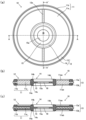
つぎに、図1に示した一実施形態に係るシールワッシャ10及びその取付構造について、図1~図3を参照しながら説明する。図1(a)は同シールワッシャ10の平面図であり、図1(b)は同A-A線矢視縦断面図であり、図1(c)は同A´-A´線矢視縦断面図である。図2及び図3はシールワッシャ10の取付構造を示した図であり、図2はシールワッシャ10の使用形態(時系列、1/2)を示す切断部端面図及び一部拡大図であり、図3はシールワッシャ10の使用形態(時系列、2/2)を示す切断部端面図及び一部拡大図である。
Next, the seal washer 10 and its mounting structure according to the embodiment shown in FIG. 1 will be described with reference to FIGS. 1 to 3. FIG. 1(a) is a plan view of the
以下では、シールワッシャ10について、シールワッシャ10の固定具30の締結部31側を「固定側」と記述し、シールワッシャ10の相手部材1側を「相手側」と記述して説明する。なお、他の実施形態の説明図である図4~図6に図示したシールワッシャ10A~10Gについても同様である。
In the following description of the
図1のシールワッシャ10は、図1(a)に示すように環状体とされ、金属よりなる環状の芯材11と、弾性材よりなる弾性シール部12と、弾性材よりなる係合片15とを一体に備えてなる。芯材11の材料としては鉄、銅、アルミなどの金属材料のほか、硬質の合成樹脂材料が挙げられる。弾性材としては、ゴムや、弾性を有する軟質の合成樹脂が挙げられる。
The
芯材11は、芯材本体11aと、芯材本体11aの外周側に設けられたシール基部11bとを備えている。芯材本体11aは略均一な厚さとされ、断面視略長方形とされる。シール基部11bは、芯材本体11aの約1/3程度の厚さの環状板片であり、芯材本体11aの外周端の厚さ方向の略中央より外側に芯材本体11aと略平行に延びるように形成されている。
The
弾性シール部12は、シールワッシャ10の外周部に配される外側シール部13と、シールワッシャ10の内周部に配される内側シール部14とを備えている。内側シール部14の内周側の端面14dには、その端面14dの厚さ方向の略中央より内側に芯材本体11aと略平行に突出した環状の板状片よりなる係合片15が設けられている。なお、本図例では係合片15は、弾性シール部12と同一素材の弾性材で一体成形にて製されている。
The
係合片15は、シールワッシャ10の使用において係合片15の内側の空間(円形の開口部18)を貫通するように配される、固定具(ボルト)30の軸部32に係合するものであればよい。すなわち、係合片15が軸部32を周囲より軽く押圧するか、係合片15の先端15aが雄ねじ部33のねじ溝33aに入り込むか、あるいは係合片15の先端15aが雄ねじ部33のねじ山33bに引っ掛かることにより、係合片15が軸部32を抱持してシールワッシャ10/ボルト30間が相互に仮固定されればよい。なお、図1の例の係合片15は、先端15aがねじ溝33aに入り込みやすくするために略半円形状とされている。
The
したがって、係合片15により囲まれた開口部18の径は、本シールワッシャ10が取り付けられるボルト30の軸部32の径と略合致するか、軸部32の径よりもやや小さめとされる。なお、係合片15による係合は、軸部32のネック部34(非ねじ部)に対するものであってもよい。
Therefore, the diameter of the
この係合片15は、相手部材1の固定作業における、少なくとも内側シール部14の弾性変形の発生以前において、先端15aがボルト30の軸部32の周面に係合するものであればよい。なお、シールワッシャ10(の係合片15)と、ボルト30(の軸部32)との係合は後述するように、ボルト30で相手部材1の取付部材20への固定が進行していくうちに係合が解除されるものであってもよい。
The
ようするに係合片15は、少なくとも相手部材1の取付部材20に対する固定作業の前段階において、ボルト30とシールワッシャ10とを仮一体化できるものであればよい。つまり、この仮一体化によれば、ボルト30とシールワッシャ10とよりなる一組の両部材を仮一体化状態で一体として取り扱うことができ、その結果、一組の両部材の作業前の保管や運搬などにおいて、両部材が分離されて一方の部材を紛失することを防止することができる。
In other words, the
また、本図例におけるシールワッシャ10の芯材11、外側シール部13、内側シール部14及び係合片15の各部は、表裏において対称形状とされ、シールワッシャ10全体としても、表裏において対称形状とされる。
In addition, the
外側シール部13は、シール基部11bの厚さ方向の両面(固定側の面、相手側の面)のそれぞれに分離されて状態で固着され、図1(b)(c)に示すように、外側シール(固定側)13aは芯材本体11aの固定側表面11aaよりも突出し、外側シール(相手側)13bは芯材本体11aの相手側表面11abよりも突出している。
The
また、内側シール部14は内側シール本体14aを備えるとともに、内側シール本体14aの固定側には芯材本体11aの固定側表面11aaよりも突出した固定側凸部14bを有し、内側シール本体14aの相手側には芯材本体11aの相手側表面11abよりも突出した相手側凸部14cを有している。
The
なお、外側シール部13及び内側シール部14の厚さ方向への突出の程度は、図例では内側シール部14の突出程度が外側シール部13の突出程度よりもやや大きいが、これには限られない。
In addition, the degree to which the
シールワッシャ10は、芯材11と弾性シール部12と係合片15とを射出成形型による2色成形で一体に製されればよいが、芯材11に対し、別成形された弾性シール部12と係合片15とを後付けするものであってもよい。なお、本図例のものは2色成形によるものであるため、内側シール部14と外側シール部13とは表裏面に表れる繋ぎ部12aでつながっている(図1(a)(c)参照)。
The
ボルト30及びシールワッシャ10は、図2に示すように、ボルト30の軸部32を挿通させる挿通孔2を有する板状の相手部材1を、雌ねじ部(埋め込みナット部)21を有する取付部材20に固定するために用いられる。
As shown in FIG. 2, the
つまり、ボルト30の軸部32の雄ねじ部33(図1の拡大図参照)は取付部材20の雌ねじ部21と螺合関係にあり、相手部材1はボルト30の締結部(ボルト頭)31と取付部材20との間に挟まれるように固定される。シールワッシャ10は、ボルト頭31の裏面と相手部材1の表面との間に配されるようにして用いられる。
In other words, the male threaded portion 33 (see the enlarged view in FIG. 1) of the
図2は、ボルト30の雄ねじ部33と取付部材20の雌ねじ部21とが螺合状態にあり、シールワッシャ10がボルト頭31と相手部材1との間に挟まれた状態にあり、固定作業の中途状態を示した図である。図3は、図2の状態からボルト30を螺進させ、相手部材1が取付部材20に固定された状態を示した図である。
Figure 2 shows the male threaded
このシールワッシャ10の取付構造において、シールワッシャ10、相手部材1及びボルト30の3者間における寸法関係は、つぎの関係式とされる。なお、各関係式における径、内径、外径は半径であり、つまり中心軸Lからの寸法とされる(図2(a)参照)。
In this mounting structure for the
外側シール部13の内径r1 > ボルト頭31の外径r2
外側シール部13の内径r1 > 相手部材1の挿通孔2の径r3
相手部材1の挿通孔2の径r3 > 芯材11の内径r4(内側シール部14の外径)
ボルト頭31の外径r2 > 芯材11の内径r4
なお、ボルト頭31の外径r2と、挿通孔2の径r3との関係は定められていないが、本図例では、r2>r3となっている。
Inner diameter r1 of
Inner diameter r1 of the
Diameter r3 of the
Outer diameter r2 of
The relationship between the outer diameter r2 of the
前記関係式は、外側シール部13が表面側においてボルト頭31とは相対せず(つまり外側シール部13の表面側は空間である)、外側シール部13が裏面側において相手部材1の表面と相対し、内側シール部14が表面側においてボルト頭31の裏面と相対し、内側シール部14が裏面側において挿通孔2による空間と相対していることを表現している。
The above relational expression expresses that the
ボルト30と取付部材20との螺合による図2の状態では、外側シール部13の外側シール(相手側)13bが相手部材1の表面1aに接触している一方、内側シール部14の固定側凸部14bがボルト頭31の裏面に接触している。そして、螺合をさらに進めることで、それ以上螺進させることができない、全部材が相互に固定された図3の状態となる。
In the state shown in FIG. 2, where the
図3の状態では、外側シール部13の外側シール(相手側)13bは相手部材1の表面1aに弾接し圧縮される。このとき外側シール(固定側)13aは図2の状態と比べて形状の変動はない。
In the state shown in FIG. 3, the outer seal (mating side) 13b of the
この弾接状態では、外側シール部13の外側シール(相手側)13bはシールワッシャ10の厚さ方向においてシール基部11bにより固定側よりバックアップされているので、反力(弾接力、弾性復帰力)が大きくなり、その結果、シールワッシャ10の外側シール部13は相手部材1の表面にしっかりと密接する。
In this elastic contact state, the outer seal (mating side) 13b of the
このようにして、シールワッシャ10は挿通孔2の周囲の環状部全周において挿通孔2への水分の浸入を抑制して、シールの役割を果たす。
In this way, the
一方、内側シール部14の固定側凸部14bがボルト頭31の裏面に弾接し、それとともに内側シール部14の全体が挿通孔2の空間側にボルト30に押圧されて弾性変形し、一部が挿通孔2に入り込んでいく。
Meanwhile, the fixed
ようするに、内側シール部14は、外側シール部13の外側シール(相手側)13bのように芯(シール基部11b)でバックアップされている構造ではないため、押圧による弾性復帰力は少ししか発生せず、よって反力は小さく、外側シール部13の外側シール(相手側)13bよりも大きく変形し、挿通孔2の空間へ倒れ込んでいく。このように挿通孔2は内側シール部14の逃げ空間として位置付けられる。
In other words, since the
そして、内側シール部14の挿通孔2への倒れ込みとともに、ボルト頭31の裏面による押圧により内側シール部14の固定側凸部14bが弾性変形し、その表面は芯材本体11aの固定側表面11aaと略面一になってボルト頭31が芯材11に対して略均一に接触する(図3参照)。
As the
このようにして、図2の状態においてボルト頭31とシールワッシャ10との間にできていた隙間S(図2参照)は、ほぼ消滅する。このように隙間Sがほぼ消滅するため、シールワッシャ10の表面側からの水浸入も抑制することができる。
In this way, the gap S (see FIG. 2) that was formed between the
なお、外側シール部13はボルト頭31よりも外側に配され、ボルト30とは直接接触せず弾接関係が形成されないため、外側シール部13がシールワッシャ10の表面側からの水浸入を抑止することはないが、代わりに内側シール部14が前記のように作用するため表面側からの水浸入を抑制できる。
The
また、図2の状態のように、シールワッシャ10が相手部材1(取付部材20)とボルト頭31との間に接触するように挟まれて、外側シール部13による大きな反力が継続発生しても、内側シール部14が逃げ空間である挿通孔2へ倒れ込んでいくので、ボルト30の螺合はスムースに進行する。
In addition, as shown in Figure 2, even if the
ようするに、内側シール部14を相手部材1の挿通孔2の径方向の内方に配することで、ボルト30の締結の終盤タイミングにおいて大きな力を必要とせず操作がしやすくなり、その結果、ボルト30の締結をスムースに完了させることができる。
In other words, by arranging the
本実施形態では内側シール部14をスムースに挿通孔2へ倒れさせるために、前述したように外側シール部13がボルト頭31よりも外側に配されるようにして、外側シール部13がボルト頭31との関係において内側シール部14の動作の邪魔をしないように構成されているが、この関係(外側シール部13の内径r1>ボルト頭31の外径r2)には限られない。
In this embodiment, in order to allow the
内側シール部14のスムースな挿通孔2への倒れ込みを実現するためには、少なくとも外側シール部13がボルト頭31に対し弾接関係とならないような相互の関係があればよい。なお、この関係については図5(b)(c)の説明とともに後述する。
In order to achieve smooth collapse of the
また、内側シール部14が挿通孔2へ倒れることで、図2、図3の拡大図に示すように、係合片15の軸部32に対する係合が解除される。その結果、係合片15と軸部32との係合による反力はなくなり、それによってもボルト30の螺進はしやすくなるし、ボルト30の回転によりシールワッシャが供回りすることも回避できる。
In addition, by the
なお、係合片15の本来の機能(ボルト30とシールワッシャ10の仮一体化)を発揮させるためには、係合片15と軸部32との係合による反力が外側シール部13の反力よりも十分に小さな係合であってもよく、そのような弱い係合力の係合であれば、ボルト30の螺進が進んでも係合が解除されないものであっても問題はない。
In order for the
また、図1に示した本シールワッシャ10は、厚さ方向において対称形状であり、つまり固定側の面であるか、相手側の面であるかの区別がほとんどない。そのため、シールワッシャ10を、表裏を気にすることなく使用することができる。
In addition, the
以上のように、シール性を高く保持でき、かつボルト30の螺着による相手部材1の固定をスムースに行うためには、前述したように、シールワッシャ10、相手部材1及びボルト30の3者間における寸法関係が成立していればよい。
As described above, in order to maintain high sealing performance and smoothly fasten the
すなわち、
外側シール部13の内径r1 > ボルト頭31の外径r2
外側シール部13の内径r1 > 相手部材1の挿通孔2の径r3
相手部材1の挿通孔2の径r3 > 芯材11の内径r4(内側シール部14の外径)
ボルト頭31の外径r2 > 芯材11の内径r4
であればよい。
That is,
Inner diameter r1 of
Inner diameter r1 of the
Diameter r3 of the
Outer diameter r2 of
That's fine.
図4に示したシールワッシャ10Aの取付構造も、前記関係式を満たしている。この図例のものは、相手部材1の挿通孔2の径r3が図1のものよりも大きいが、前記関係式を満たしているため、図1のものと同様の効果が奏せられる。
The mounting structure of the
この図例に示すように、ボルト頭31の外径r2と挿通孔2の径r3とは、r2≦r3の関係であってもよく、つまりボルト頭31の外径r3よりも挿通孔2の径r3が大きな相手部材1を取付固定する場合でも、前記関係式を満たす限りは図1のものと同様の効果が奏せられる。
As shown in this example, the outer diameter r2 of the
また、図4に示したシールワッシャ10Aは図1に示したものとは異なり、外側シール部13として外側シール(相手側)13bのみよりなる(外側シール(固定側)13aが存在しない)ものが採用され、内側シール部14として相手側凸部14cが存在しないものが採用されている。
The
このようなシールワッシャ10Aであっても、外側シール部13の相手部材1への弾接ならびに内側シール部14の挿通孔2への倒れ込み及び固定側凸部14bと芯材本体11aとの面一化には特段の問題はなく、図1のシールワッシャ10と同様の効果が奏せられる。
Even with this type of
シールワッシャ10、10Aの形状としては、図1や図4のものには限られず、他の実施形態に係る、図5(a)~(e)に示したシールワッシャ10B~10Fであってもよい。
The shape of the
図5(a)のシールワッシャ10Bは、外側シール部13が外側シール(固定側)13aと外側シール(相手側)13bとを備え、さらに外側シール(固定側)13aと外側シール(相手側)13bとを連結した連結部13cを備えている。この連結部13cはシール基部11bの外周側の端面を覆うように配設されている。
The
なお、外側シール(相手側)13bは芯材本体11aの相手側表面11abよりも突出し、外側シール(固定側)13aは芯材本体11aの固定側表面11aaよりも突出している。また、内側シール部14は図1(a)のものと同様のものとされる。
The outer seal (mating side) 13b protrudes beyond the mating surface 11ab of the
外側シール部13が連結部13cを備えて表裏一体とされているため、芯材11とは別成形した外側シール部13を芯材11に対して後付けすることがしやすい。例えば、外側シール部13を内側シール部14とは別の弾性材にする場合や、外側シール部13の相手部材1側への突出度合いを相手部材1の種類などに対応させて種々異ならせて取り替え可能に複数の外側シール部13を準備する場合に、使い勝手がよい。
Since the
図5(b)のシールワッシャ10Cは、外側シール部13が外側シール(固定側)13aと外側シール(相手側)13bとを備えているが、外側シール(固定側)13aの表面は芯材本体11aの固定側表面11aaと略面一の面とされる。なお、外側シール(相手側)13bは芯材本体11aの相手側表面11abよりも突出している。
In the
外側シール部13がこのような形状であるため、弾性材の省材料化を図れる。また、内側シール部14よりも外側の表面が略面一となっているため、ボルト頭31が外側シール部13を上方より覆うようなボルト30を用いた場合でも、相手部材1の固定作業において外側シール(固定側)13aがボルト頭31に対し弾接するおそれはほとんどなく、内側シール部14の挿通孔2への倒れ込みをスムースに実現できる。なお、内側シール部14は図1(a)のものと同様のものとされる。
The shape of the
図5(c)のシールワッシャ10Dは、外側シール部13が外側シール(固定側)13aを備えておらず、芯材本体11aの相手側表面11abよりも突出した外側シール(相手側)13bのみを備えている。そして、シール基部11bの固定側の表面が芯材本体11aの固定側表面11aaと略面一に形成されている。
In the
このように外側シール(相手側)13bのみによる外側シール部13であるため、弾性材の省材料化を図れる。また、外側シール(固定側)13aが存在せず、かつ内側シール部14よりも外側の表面が略面一となっているため、ボルト頭31が外側シール部13を上方より覆うようなボルト30を用いた場合でも、相手部材1の固定作業において外側シール部13がボルト頭31に対し弾接するおそれはほとんどなく、内側シール部14の挿通孔2への倒れ込みをスムースに実現できる。なお、内側シール部14は図1(a)のものと同様のものとされる。
As the
このように、図5(b)(c)に示したシールワッシャ10C、10Dは、シールワッシャ10とボルト30との関係において、図2等で示したような、外側シール部13の内径r1>ボルト頭31の外径r2の寸法関係は成立しなくてもよい。
In this way, in the
ようするに、これらのシールワッシャ10C、10Dを、ボルト頭31が外側シール部13を上方より覆うようなボルト30に使用した場合でも、内側シール部14の挿通孔2への倒れ込みはスムースになされ得る。
In other words, even when these
図5(d)のシールワッシャ10Eは、外側シール部13が図1のものと同様とされ、外側シール(固定側)13aと外側シール(相手側)13bとを備えている。
The
また、芯材11の芯材本体11aは、内周側の端部に内側シール部14を連結するための被挟持部11acを備えている。この被挟持部11acは、芯材本体11aの約1/3程度の厚さであって、シール基部11bと同様の環状板片であり、芯材本体11aの内周端の厚さ方向の略中央より内側に延びるように設けられている。内側シール本体14a、固定側凸部14b及び相手側凸部14cは、被挟持部11acよりも内周側に設けられている。
The
内側シール部14は、内側シール本体14aと固定側凸部14bと相手側凸部14cとに加え、固定側挟持片14eと相手側挟持片14fとを備えており、固定側挟持片14eと相手側挟持片14fとで芯材本体11aの被挟持部11acを挟持するように芯材本体11aに固着されている。
The
内側シール部14が表裏側に一対の挟持片を備えているため、内側シール部14を別成形した場合には芯材11に対して後付けがしやすくなる。例えば、内側シール部14を外側シール部13とは別の弾性材を材料とする場合や、内側シール部14の固定具30側への突出度合いを固定具30の種類などに対応させて種々異ならせる場合に、使いやすい。
Since the
なお、芯材本体11aの被挟持部11acはシール基部11bとは機能が異なり、シール基部11bのような弾性材の後方に控えて弾接をバックアップするものではない。ただし、挟持片の厚みの調整などで挟持態様を種々異ならせることで、内側シール部14(内側シール本体14a、固定側凸部14b、相手側凸部14c)の倒れ込みの程度を異ならせることは可能である。
The clamped portion 11ac of the
図5(e)のシールワッシャ10Fは、全体のシルエットとしては図1のものと略同一であるが、係合片15が別成形されている点、及びその素材が内側シール部14を構成する弾性材ではない点で、図1のものとは相違する。
The
この係合片15は、内側シール部14の材料よりも剛性が高い、例えば硬質のPETなどの合成樹脂材料よりなる環状板片とされる。この環状板片は、内側シール部14の内側シール本体14aの内周側の端面14dに設けた差し込み溝14gに差し込まれて係合片15として作用する。
The
この係合片15は図1などに採用された係合片15よりも弾性が低く、内側シール部14の弾性変形の際の係合片15自体の弾性変形は内側シール部14に比べ小さいが、内側シール部14の全体が挿通孔2の空間へ倒れ込むように撓むため、その動作に伴って、図3(b)と同様に係合が解除され傾いていく。
This
このように係合片15が別成形されているため、係合片15の寸法を種々異ならせて、ボルト30の軸部32の径に合わせるように、係合片15を取り替えることができる。
Since the
なお、図5に示した5例に関するシールワッシャ10B~10Fの取付構造、つまりボルト30及び相手部材1に対する取付構造については説明及び図示を省略する。これらのシールワッシャ10B~10Fについても、各部の径r1、r4と、相手部材1の挿通孔2の径r3、ボルト頭31の径r2との関係において、前述した関係式が成立すればよい。なお前述したように、図5(b)(c)に示したシールワッシャ10B、10Cについては、外側シール部13の内径r1>ボルト頭31の外径r2の関係は成立しなくてもよい。
The mounting structure of the
また、図6に示すように、係合片15が周方向に沿って断続的に形成された、つまり係合片15が複数の分離片16で構成されたシールワッシャ10Gを使用することもできる。
Also, as shown in FIG. 6, a
このように係合片15が周方向に沿って断続的に形成されていれば、ボルト30の螺進の進行とともに、ボルト30の軸部32への係合が解除されやすくなるので、係合片15による反力が軽減され、使いやすくなる。特に、別成形されたの硬質の分離片16を用いれば、分離されたことにより係合の解除がされやすくなり都合がよい。また、別成形されたの係合片15の場合には、分離片16とすることで装着もしやすくなるため利便性がよい。
If the
なお、図6のシールワッシャ10Gの構成は、係合片15の形状、構成以外は図1のものとおおむね同様であるため、図6では同一の構成部について同一の符号を付して、その説明は割愛する。
The configuration of the
以上の実施形態としては固定具30の締結部31をボルト頭31とした例を示したが、締結部31がナットやリングワッシャであってもよい。つまり、ナットやリングワッシャと相手部材1との間に本シールワッシャ10、10A~10Gを配する使用形態であってもよい。
In the above embodiment, the
また、取付部材20の雌ねじ部21としては、埋め込みナット部に代えて、バーリング加工で形成された雌ねじ部21であってもよい。なお、以上に説明した複数の実施形態に係るシールワッシャ10、10A~10G及びシールワッシャ10、10A~10Gの取付構造は一例にすぎず、各図例以外の構成、形状に適宜変更が可能であることは言うまでもない。
In addition, the
1 相手部材
1a 表面
2 挿通孔
10、10A~10G シールワッシャ
11 芯材
11a 芯材本体
11aa 固定側表面
11ab 相手側表面
11b シール基部
12 弾性シール部
12a 繋ぎ部
13 外側シール部
13a 外側シール(固定側)
13b 外側シール(相手側)
14 内側シール部
14a 内側シール本体
14b 固定側凸部
14c 相手側凸部
14d 内周側の端面
15 係合片
15a 先端
16 分離片
20 取付部材
21 雌ねじ部(埋め込みナット部)
30 固定具(ボルト)
31 締結部(ボルト頭)
32 軸部
r1 外側シール部の内径
r2 締結部(ボルト頭)の外径
r3 相手部材の挿通孔の径
r4 芯材の内径
REFERENCE SIGNS
13b Outer seal (counterpart)
14
30 Fixtures (bolts)
31 Fastening part (bolt head)
32 Shaft portion r1 Inner diameter of outer seal portion r2 Outer diameter of fastening portion (bolt head) r3 Diameter of insertion hole of mating member r4 Inner diameter of core material
Claims (5)
環状の芯材と、該芯材の外周側の端部に固着された弾性材よりなる外側シール部と、該芯材の内周側の端部に固着された弾性材よりなる内側シール部と、を備え、
前記芯材は、芯材本体と、該芯材本体より外周側に延出したシール基部と、を備え、
前記外側シール部は、前記シール基部の厚さ方向の2面のうちの前記相手部材側を向く面に、前記芯材本体の表面よりも突出するように配されており、
前記内側シール部は、前記芯材本体の内周側の端面に、さらに内側に突出するように、かつ前記締結部側に向け前記芯材本体の表面よりも突出するように配されており、
前記外側シール部の内径が前記挿通孔の径よりも大とされ、前記挿通孔の径が前記芯材の内径よりも大とされ、かつ、前記締結部の外径が前記芯材の内径よりも大とされることを特徴とするシールワッシャ。 A seal washer is disposed between a fastening portion of a fixture having a fastening portion and a shaft portion and a mating member having an insertion hole through which the shaft portion is inserted,
The seal member includes an annular core material, an outer seal portion made of an elastic material and attached to an outer peripheral end portion of the core material, and an inner seal portion made of an elastic material and attached to an inner peripheral end portion of the core material,
The core material includes a core material body and a seal base portion extending from the core material body toward an outer periphery thereof,
The outer seal portion is disposed on one of two surfaces of the seal base in a thickness direction, the surface facing the mating member, so as to protrude from a surface of the core body,
the inner seal portion is disposed on an end surface on an inner circumferential side of the core body so as to protrude further inward and protrude beyond a surface of the core body toward the fastening portion,
A seal washer characterized in that the inner diameter of the outer seal portion is larger than the diameter of the insertion hole, the diameter of the insertion hole is larger than the inner diameter of the core material, and the outer diameter of the fastening portion is larger than the inner diameter of the core material.
前記内側シール部の内周側の端面より内側に突出した係合片をさらに備え、
前記係合片は、前記内側シール部よりも薄厚の板状片とされ、少なくとも前記内側シール部が弾性変形していない状態においては、先端が前記軸部の周面に係合することを特徴とするシールワッシャ。 In claim 1,
The inner seal portion further includes an engagement piece protruding inward from an end surface on an inner circumferential side thereof,
A seal washer characterized in that the engaging piece is a plate-shaped piece thinner than the inner seal portion, and its tip engages with the circumferential surface of the shaft portion at least when the inner seal portion is not elastically deformed.
前記係合片は、周方向に沿って断続的に形成されていることを特徴とするシールワッシャ。 In claim 2,
The seal washer is characterized in that the engagement pieces are formed intermittently along a circumferential direction.
前記軸部にはねじ溝が形成されており、該ねじ溝に前記係合片の先端が係合し得ることを特徴とするシールワッシャ。 In claim 2,
A seal washer characterized in that a screw groove is formed on the shaft portion, and a tip of the engagement piece can engage with the screw groove.
請求項1~4のいずれか1項に記載のシールワッシャを用いることを特徴とするシールワッシャの取付構造。
A mounting structure for a seal washer is provided between a fastening portion of a fastener having a fastening portion and a shaft portion, and a mating member having an insertion hole through which the shaft portion is inserted,
A mounting structure for a seal washer, comprising the seal washer according to any one of claims 1 to 4.
Priority Applications (4)
| Application Number | Priority Date | Filing Date | Title |
|---|---|---|---|
| JP2023137535A JP2025031360A (en) | 2023-08-25 | 2023-08-25 | Seal washer and its mounting structure |
| CN202410580210.6A CN119508483A (en) | 2023-08-25 | 2024-05-11 | Sealing gasket and its installation structure |
| US18/787,612 US20250067300A1 (en) | 2023-08-25 | 2024-07-29 | Seal washer and mounting structure of the same |
| DE102024121539.9A DE102024121539A1 (en) | 2023-08-25 | 2024-07-29 | sealing disc and its installation structure |
Applications Claiming Priority (1)
| Application Number | Priority Date | Filing Date | Title |
|---|---|---|---|
| JP2023137535A JP2025031360A (en) | 2023-08-25 | 2023-08-25 | Seal washer and its mounting structure |
Publications (1)
| Publication Number | Publication Date |
|---|---|
| JP2025031360A true JP2025031360A (en) | 2025-03-07 |
Family
ID=94484361
Family Applications (1)
| Application Number | Title | Priority Date | Filing Date |
|---|---|---|---|
| JP2023137535A Pending JP2025031360A (en) | 2023-08-25 | 2023-08-25 | Seal washer and its mounting structure |
Country Status (4)
| Country | Link |
|---|---|
| US (1) | US20250067300A1 (en) |
| JP (1) | JP2025031360A (en) |
| CN (1) | CN119508483A (en) |
| DE (1) | DE102024121539A1 (en) |
Family Cites Families (28)
| Publication number | Priority date | Publication date | Assignee | Title |
|---|---|---|---|---|
| US3170701A (en) * | 1961-05-15 | 1965-02-23 | Prec Rubber Products Corp | Sealing washer |
| US3500712A (en) * | 1968-07-11 | 1970-03-17 | Illinois Tool Works | Sealing washer unit |
| US3726178A (en) * | 1971-06-25 | 1973-04-10 | Apm Corp | Multiple purpose sealing washer for threaded and cylindrical shanks |
| US4026183A (en) * | 1976-05-17 | 1977-05-31 | Illinois Tool Works Inc. | Sealing washer |
| US4270759A (en) * | 1977-02-14 | 1981-06-02 | Garlock Inc. | Combination thrust washer and seal article, apparatus and method |
| US4191389A (en) * | 1977-10-26 | 1980-03-04 | Parker-Hannifin Corporation | Sealing washer |
| US4702657A (en) * | 1986-06-27 | 1987-10-27 | Parker Hannifin Corporation | Self centering seal |
| US5183267A (en) * | 1987-12-10 | 1993-02-02 | Chicago Rawhide Manufacturing Co. | Seal for sending unit |
| US5011162A (en) * | 1989-07-20 | 1991-04-30 | Parker Hannifin Corporation | Bi-lobed sealing element and retainer |
| US5201625A (en) * | 1990-04-23 | 1993-04-13 | Yazaki Corporation | Connector housing of threaded connection type having sealing member and bolt for securing the housing |
| US5188495A (en) * | 1992-02-28 | 1993-02-23 | Illinois Tool Works Inc. | Fastener assembly useful as drain plug |
| JP2000249132A (en) * | 1999-02-26 | 2000-09-12 | Sumitomo Heavy Ind Ltd | Seal washer |
| JP2005098378A (en) * | 2003-09-24 | 2005-04-14 | Smc Corp | gasket |
| NZ537537A (en) * | 2004-12-24 | 2008-03-28 | Dale Michael Mcintyre | Sanitary washer having peripheral annular rebate on upper and lower faces filled with flexible medium |
| US8186691B2 (en) * | 2006-02-17 | 2012-05-29 | Parker-Hannifin Corporation | Composite seal and coupling |
| US8955851B2 (en) * | 2006-11-27 | 2015-02-17 | Kenji Matsumoto | Metalannular gasket |
| JP2008255975A (en) * | 2007-03-12 | 2008-10-23 | Uchiyama Mfg Corp | Vibration damping washer |
| US7854434B2 (en) * | 2007-04-12 | 2010-12-21 | Ti Group Automotive Systems, L.L.C. | Ring seal with axially-opposed radially-offset seal beads |
| DE102011120724A1 (en) * | 2011-12-12 | 2013-06-13 | Carl Freudenberg Kg | Sealing, screwing with the seal and their respective use |
| US9441664B2 (en) * | 2012-11-26 | 2016-09-13 | Aoyama Seisakusho Co., Ltd. | Seal washer |
| DE102014118342A1 (en) * | 2013-12-17 | 2015-06-18 | Richard Bergner Verbindungstechnik Gmbh & Co. Kg | Method for captive application of a washer to the shank of a screw |
| EP3211720A1 (en) * | 2016-02-29 | 2017-08-30 | Dubuis et Cie | Earthing bond seal |
| US10184503B2 (en) * | 2016-03-18 | 2019-01-22 | Toyota Jidosha Kabushiki Kaisha | Fastening structure |
| JP7144836B2 (en) * | 2018-08-02 | 2022-09-30 | 内山工業株式会社 | Resin molded product and its manufacturing method |
| JP6987214B2 (en) * | 2019-09-27 | 2021-12-22 | 東芝三菱電機産業システム株式会社 | Fastening structure |
| JP6797323B1 (en) * | 2020-03-31 | 2020-12-09 | 株式会社トープラ | Screw fastener |
| FR3114854B1 (en) * | 2020-10-07 | 2022-10-14 | Airbus Operations Sas | GASKET WITH SKIRT |
| JP2024128171A (en) * | 2023-03-10 | 2024-09-24 | 株式会社青山製作所 | Seal Washer |
-
2023
- 2023-08-25 JP JP2023137535A patent/JP2025031360A/en active Pending
-
2024
- 2024-05-11 CN CN202410580210.6A patent/CN119508483A/en active Pending
- 2024-07-29 DE DE102024121539.9A patent/DE102024121539A1/en active Pending
- 2024-07-29 US US18/787,612 patent/US20250067300A1/en active Pending
Also Published As
| Publication number | Publication date |
|---|---|
| CN119508483A (en) | 2025-02-25 |
| US20250067300A1 (en) | 2025-02-27 |
| DE102024121539A1 (en) | 2025-02-27 |
Similar Documents
| Publication | Publication Date | Title |
|---|---|---|
| US3170701A (en) | Sealing washer | |
| JP6797323B1 (en) | Screw fastener | |
| TWI721764B (en) | Lock nut set | |
| US4266591A (en) | Locking connector | |
| US20130064624A1 (en) | Lock nut and a fastening unit comprising the same | |
| JP7556744B2 (en) | Connection structure | |
| JPWO2014061122A1 (en) | Nut with seal washer | |
| JP2025031360A (en) | Seal washer and its mounting structure | |
| CN117145851A (en) | Wedge clamp lock nut | |
| JP2006118582A (en) | Female screw part | |
| JP2020092515A (en) | Cable gland | |
| KR200322158Y1 (en) | soil pipe connect structure with Pressure ring | |
| JP2024147919A (en) | bolt | |
| CN111102410B (en) | Joint for flexible pipe and locking member for the joint | |
| JP6491773B1 (en) | Fastening structure | |
| CN223136686U (en) | Self-locking nut | |
| CN222363249U (en) | Pressure-bearing connection structure and shell | |
| JP7645528B2 (en) | Tube connection structure | |
| TWM594651U (en) | Anti-loose nut set | |
| CN218882716U (en) | Plastic fastener | |
| CN223089757U (en) | Connecting sleeve set and fastening mechanism | |
| KR101561839B1 (en) | anti-loose nut | |
| CN223105007U (en) | A nut assembly | |
| CN211901246U (en) | Anti-loose nut | |
| JP2007327535A (en) | Screw anti-loosening structure |