JP2025007244A - Information processing device, control method thereof, and program - Google Patents
Information processing device, control method thereof, and program Download PDFInfo
- Publication number
- JP2025007244A JP2025007244A JP2023108517A JP2023108517A JP2025007244A JP 2025007244 A JP2025007244 A JP 2025007244A JP 2023108517 A JP2023108517 A JP 2023108517A JP 2023108517 A JP2023108517 A JP 2023108517A JP 2025007244 A JP2025007244 A JP 2025007244A
- Authority
- JP
- Japan
- Prior art keywords
- information processing
- processing device
- token
- power saving
- access
- Prior art date
- Legal status (The legal status is an assumption and is not a legal conclusion. Google has not performed a legal analysis and makes no representation as to the accuracy of the status listed.)
- Pending
Links
Images






Classifications
-
- H—ELECTRICITY
- H04—ELECTRIC COMMUNICATION TECHNIQUE
- H04L—TRANSMISSION OF DIGITAL INFORMATION, e.g. TELEGRAPHIC COMMUNICATION
- H04L9/00—Cryptographic mechanisms or cryptographic arrangements for secret or secure communications; Network security protocols
- H04L9/32—Cryptographic mechanisms or cryptographic arrangements for secret or secure communications; Network security protocols including means for verifying the identity or authority of a user of the system or for message authentication, e.g. authorization, entity authentication, data integrity or data verification, non-repudiation, key authentication or verification of credentials
- H04L9/321—Cryptographic mechanisms or cryptographic arrangements for secret or secure communications; Network security protocols including means for verifying the identity or authority of a user of the system or for message authentication, e.g. authorization, entity authentication, data integrity or data verification, non-repudiation, key authentication or verification of credentials involving a third party or a trusted authority
- H04L9/3213—Cryptographic mechanisms or cryptographic arrangements for secret or secure communications; Network security protocols including means for verifying the identity or authority of a user of the system or for message authentication, e.g. authorization, entity authentication, data integrity or data verification, non-repudiation, key authentication or verification of credentials involving a third party or a trusted authority using tickets or tokens, e.g. Kerberos
-
- G—PHYSICS
- G06—COMPUTING OR CALCULATING; COUNTING
- G06F—ELECTRIC DIGITAL DATA PROCESSING
- G06F21/00—Security arrangements for protecting computers, components thereof, programs or data against unauthorised activity
- G06F21/60—Protecting data
- G06F21/62—Protecting access to data via a platform, e.g. using keys or access control rules
-
- G—PHYSICS
- G06—COMPUTING OR CALCULATING; COUNTING
- G06F—ELECTRIC DIGITAL DATA PROCESSING
- G06F2221/00—Indexing scheme relating to security arrangements for protecting computers, components thereof, programs or data against unauthorised activity
- G06F2221/21—Indexing scheme relating to G06F21/00 and subgroups addressing additional information or applications relating to security arrangements for protecting computers, components thereof, programs or data against unauthorised activity
- G06F2221/2141—Access rights, e.g. capability lists, access control lists, access tables, access matrices
Landscapes
- Engineering & Computer Science (AREA)
- Computer Security & Cryptography (AREA)
- Theoretical Computer Science (AREA)
- Software Systems (AREA)
- Computer Hardware Design (AREA)
- General Health & Medical Sciences (AREA)
- Health & Medical Sciences (AREA)
- Physics & Mathematics (AREA)
- General Engineering & Computer Science (AREA)
- General Physics & Mathematics (AREA)
- Bioethics (AREA)
- Computer Networks & Wireless Communication (AREA)
- Signal Processing (AREA)
- Facsimiles In General (AREA)
Abstract
Description
本発明は、情報処理装置およびその制御方法とプログラムに関し、特に、複数の認可サービスに対応した機能を備える画像処理装置の省電力動作時間の向上に関する。 The present invention relates to an information processing device and a control method and program thereof, and in particular to improving the power-saving operation time of an image processing device that has functions corresponding to multiple authorization services.
近年、画像処理装置でスキャンした画像の送付先として、クラウドなどのストレージサーバやメールサーバを利用するケースが増えてきている。そのような送付先ヘのアクセスは、ユーザ名、パスワードによる認証でなく、例えば、RFC(Request For Comments) 6749で規定されたOAuth2.0など権限の認可によって発行されたアクセストークンを用いてアクセスを行う。 In recent years, there has been an increase in the use of cloud storage servers and mail servers as destinations for images scanned with image processing devices. Access to such destinations is not authenticated by a user name and password, but is instead performed using an access token issued based on authorization, such as OAuth 2.0 as specified in RFC (Request For Comments) 6749.
アクセストークンには有効期限があり、リフレッシュトークンを用いて認可サーバに要求することにより、新規のアクセストークンを取得することができる。リフレッシュトークンを用いた権限移譲システムとして、クライアントIDや、シークレットを変更することなしに、漏えいしたリフレッシュトークンを無効にすることで、より安全性を高めた権限委譲システムが知られている(特許文献1)。 Access tokens have an expiration date, and a new access token can be obtained by making a request to the authorization server using a refresh token. One authority delegation system using a refresh token is known that provides increased security by invalidating leaked refresh tokens without changing the client ID or secret (Patent Document 1).
複数の機能でそれぞれ認可サービスに対応した場合、有効期限が切れる前に複数の機能それぞれが利用するアクセストークンを更新する必要がある。更新のタイミングが省電力モードで動作中の場合は、一旦、通常モードに戻って更新処理を実施することになる。そのため、複数のアクセストークンを利用している装置において、それぞれのアクセストークンをそれぞれの有効期限の切れるタイミングで更新すると、その都度通常モードに復帰するために省電力モードでの動作時間が短くなる。 When multiple functions each support an authorization service, the access tokens used by each of the multiple functions must be updated before they expire. If the update occurs while the device is operating in power-saving mode, the device will have to return to normal mode first to perform the update process. Therefore, in a device that uses multiple access tokens, if each access token is updated when it expires, the device will have to return to normal mode each time, shortening the operating time in power-saving mode.
本発明は上記従来例に鑑みて成されたもので、複数のアクセストークンを用いても、その更新によって省電力モードでの動作期間が短縮されることの抑制を目的とする。 The present invention has been made in consideration of the above-mentioned conventional examples, and aims to prevent the operating period in power saving mode from being shortened due to updates to multiple access tokens, even when multiple access tokens are used.
上記目的を達成するために本発明は以下のような構成を有する。すなわち本発明の一側面は、所定の条件が満たされると通常モードから電力消費量がより少ない省電力モードに遷移する省電力機能を有する情報処理装置であって、
認可サーバと通信するための通信手段と、
制御手段とを有し、
前記制御手段は、
前記認可サーバから、アクセストークンとその有効期限とを取得し、
取得済みのアクセストークンの有効期限を前記アクセストークンと関連付けて保存し、
保存されている前記取得済みのアクセストークンのうちの少なくとも1つのアクセストークンの有効期限に達した場合には、前記省電力モードであれば前記通常モードに復帰して前記取得済みのアクセストークンの少なくとも一部を更新する
ことを特徴とする情報処理装置を提供する。
In order to achieve the above object, the present invention has the following configuration. That is, one aspect of the present invention is an information processing apparatus having a power saving function that transitions from a normal mode to a power saving mode in which power consumption is reduced when a predetermined condition is satisfied,
A communication means for communicating with the authorization server;
and a control means,
The control means
Obtaining an access token and its expiration date from the authorization server;
The expiration date of the obtained access token is stored in association with the access token;
An information processing device is provided, characterized in that when the expiration date of at least one of the stored acquired access tokens is reached, if in the power saving mode, it returns to the normal mode and updates at least a portion of the acquired access tokens.
本発明によれば、省電力モードでの動作時間の短縮を抑制でき、省電力効果を低下させることがない。 According to the present invention, it is possible to suppress the shortening of the operating time in power saving mode, without reducing the power saving effect.
[実施形態1]
以下、添付図面を参照して実施形態を詳しく説明する。なお、以下の実施形態は特許請求の範囲に係る発明を限定するものではない。実施形態には複数の特徴が記載されているが、これらの複数の特徴の全てが発明に必須のものとは限らず、また、複数の特徴は任意に組み合わせられてもよい。さらに、添付図面においては、同一若しくは同様の構成に同一の参照番号を付し、重複した説明は省略する。
[Embodiment 1]
Hereinafter, the embodiments will be described in detail with reference to the attached drawings. Note that the following embodiments do not limit the invention according to the claims. Although the embodiments describe a number of features, not all of these features are essential to the invention, and the features may be combined in any manner. Furthermore, in the attached drawings, the same reference numbers are used for the same or similar configurations, and duplicated descriptions are omitted.
本発明の実施形態では、画像処理装置とパーソナルコンピュータ(PC)やスマートフォンなどのクライアント端末、認可サーバ、ストレージサーバが連携するサービスの例について説明する。 In an embodiment of the present invention, an example of a service in which an image processing device cooperates with a client terminal such as a personal computer (PC) or smartphone, an authorization server, and a storage server will be described.
●システム構成
図1は、本実施形態のシステム構成の一例を示す。本実施形態におけるシステムは、多機能周辺装置(MFP)100、認可サーバ110、電子メールサーバ120、認可サーバ130、ストレージサーバ140、クライアント端末150を含む。MFP100は画像を扱う機能に着目して画像処理装置あるいは画像形成装置とも呼ばれる。また情報処理能力を持つことから情報処理装置とも呼ばれる。MFP100、認可サーバ110、電子メールサーバ120、認可サーバ130、ストレージサーバ140、クライアント端末150は、ネットワーク160を介して接続されている。ネットワーク160は、有線接続、無線接続どちらでもよく、また、インターネット、イントラネットのどちらでも構わない。例えば、無線接続、Wi-Fiであっても、データ通信回線であっても、データのやり取りが可能であればどのような形態であってもよい。MFP100、認可サーバ110、電子メールサーバ120、認可サーバ130、ストレージサーバ140、クライアント端末150は、全て同じネットワーク種別に対応していなくても構わない。例えば、MFP100、認可サーバ110、電子メールサーバ120、認可サーバ130、ストレージサーバ140は、有線でインターネットで接続されており、クライアント端末150はデータ通信回線で接続されているような形態があり得る。
System Configuration FIG. 1 shows an example of a system configuration of this embodiment. The system in this embodiment includes a multi-function peripheral (MFP) 100, an
MFP100は、画像処理装置であり、スキャナで画像を読み取ったり、プリンタで画像を印刷したりする。MFP100はユーザとの入出力を行う操作部102を有する。MFP100は電子データを紙媒体に出力するプリンタ部103を有する。MFP100は紙媒体を読み込み電子データに変換するスキヤナ部104を有する。操作部102とプリンタ部103とスキャナ部104はコントローラ部101に接続され、コントローラ部101の制御に従い複合機としての機能を実現する。MFP100の利用に際して認証を行うためのMFPユーザの情報が格納されているMFPユーザDB105がある。画像ストレージ106は、プリンタ部103で使用するデータや、スキャナ部104で変換されたデータなどの一時的な画像データが保存される一時領域と、それらより長い期間保管する必要のある画像データが保存される長期保存領域を含む。またMFP100は、通常の動作状態(通常モード)から無操作のまま予め設定された所定の時間が経過するなどの所定の条件が満たされると省電力モードに移行する省電力機能を有する。
MFP100 is an image processing device that reads images with a scanner and prints images with a printer. MFP100 has an
認可サーバ110は、認可サービス111を含んで構成される。認可サービス111が、例えば、RFC6749で規定されているOAuth2.0の仕組みに従い動作する。認可サーバ130は、認可サービス131を含んで構成される。認可サービス131が、例えば、RFC6749で規定されているOAuth2.0の仕組みに従い動作する。認可サーバ110、認可サーバ130は、公知の技術で構成されているため詳細な説明は割愛する。
The
電子メールサーバ120は、電子メールサービス121とメールボックス122を含んで構成される。電子メールサービス121は、MFP100からの指示を受けて、RFC5321で規定されたSMTP(Simple Mail Transfer Protcol)に従った電子メールの送信を行う。また、MFP100からの指示を受けて、メールボックス122に保存されたメールの取得を行う。メールの送信及び取得は、RFC5034で規定されたPOP(Post Office Protocol)やRFC3501で規定されたIMAP(Internet Message Access Protocol)に従ってよい。
The
電子メールサーバ120は、MFP100からアクセストークンを渡され、認可サーバ110へ有効なアクセストークンであるか問い合わせ、有効でない場合は、アクセスを拒絶する。電子メールサーバ120は、公知の技術で構成されているため詳細な説明は割愛する。
The
ストレージサーバ140は、ストレージサービス141とストレージ142を含んで構成される。ストレージサーバ140は、MFP100からの指示を受けて、ストレージ142に格納されたファイルの取得やディレクトリの一覧の返却、ストレージ142へのファイルの保存などを行う。
The
ストレージサーバ140は、MFP100からアクセストークンを渡され、認可サーバ130へ有効なアクセストークンであるか問い合わせ、有効でない場合は、アクセスを拒絶する。ストレージサーバ140は、公知の技術で構成されているため詳細な説明は割愛する。
The
認可サーバ110は電子メールサーバ120に関する認可を行い、認可サーバ130はストレージサーバ140に関する認可を行う。
The
クライアント端末150は、Webブラウザ151を含んで構成される。図1では、クライアント端末150は1つであるが、複数存在して構わない。クライアント端末の例として、スマートフォンやタブレット、PCなどがある。なお、図1では、本実施形態を説明するための構成だけについて述べているため、これら以外の構成を含んで構わないし、各構成要素間の接続形態もこの限りでないことは言うまでもない。
The
●MFPのコントローラ部の構成
図2はMFPのコントローラ部101の詳細を示すブロック図である。CPU201はコントローラ部101内の主な演算処理を行う。CPU201はバスを介してDRAM202と接続される。DRAM202はCPU201が演算する過程で演算命令を表すプログラムや、処理対象のデータを一時的に配置するための作業メモリとしてCPU201によって使用される。CPU201はバスを介してI/Oコントローラ203と接続される。I/Oコントローラ203はCPU201の指示に従い各種デバイスに対する入出力を行う。I/Oコントローラ203にはSATA(Serial Advanced Technology Attachment)I/F205が接続され、その先にFlashROM210が接続される。CPU201はFlashROM210をMFPの機能を実現するためのプログラム、およびドキュメントファイルを永続的に記憶するために使用する。FlashROMでなく、HDDなどの大容量記憶装置が接続されてもよい。
Configuration of the MFP Controller Unit FIG. 2 is a block diagram showing the details of the
I/Oコントローラ203にはネットワークI/F204が接続される。ネットワークI/F204には、有線LANデバイスや無線LANデバイスが接続される。CPU201は、ネットワークI/F204を介して有線LANデバイスや無線LANデバイスを制御することで、ネットワーク150上の通信を実現する。I/Oコントローラ203にはパネルI/F206が接続され、CPU201はパネルI/F206を介して操作部102に対するユーザ向けの入出力を実現する。I/Oコントローラ203にはプリンタI/F207が接続され、CPU201はプリンタI/F207を介してプリンタ部103を利用した紙媒体の出力処理を実現する。
A network I/
CPU201は、タイマ211,電源部212と電気的に接続されている。電源部212は電源スイッチを備えており、電源スイッチがONの場合はコントローラへの給電を行い、電源スイッチがOFFの場合はコントローラへの給電を停止する。ただし、電源スイッチがONの場合でも省電力モードで動作中は特定のデバイスのみに給電し、MFP100の消費電力量を低下させる。タイマ211は設定された時間を計測する時間計測を行い、設定された時間が経過したときにCPU201にタイムアップを通知する。
The
MFP100には、MFPの機能を利用するための各種アプリが存在する。一例として、コピー機能、送信機能、ファクス機能、ボックス機能などがある。例えば、コピー機能を実施する場合は、CPU201がSATA I/F205を介してFlashROM210からプログラムデータをDRAM202に読み込む。CPU201がDRAM202に読み込まれたプログラムに従い、パネルI/F206を介して操作部102に対するユーザからのコピー指示を検出する。CPU201はコピー指示を検出するとスキャナI/F208を介してスキャナ部104から原稿を電子データ(画像データ)として受け取りDRAM202に格納する。CPU201はDRAM202に格納した画像データに対して出力に適した色変換処理などを実施する。CPU201はDRAM202に格納した画像データをプリンタI/F207を介してプリンタ部103に転送し、紙媒体への出力処理を実施する。
The
送信機能は、CPU201がユーザから当該機能の指示を検出する処理については、前述のコピー機能と同じである。送信指示には、ユーザからの送信プロトコル、送信先指定、画像フォーマットなどが含まれている。送信プロトコルは、SMTP、SMB、WebDAVやFTPなどである。送信先指定は、例えば、電子メールアドレスやUniversal Naming Convention(UNC),Unified Resource Identifier(URI)などで指定される。画像フォーマットは、JPEGやPDFなどである。
The process by which the
CPU201は送信指示を検出するとスキャナI/F208を介してスキヤナ部104から原稿を電子データとして受け取りDRAM202に格納する。CPU201はDRAM202に格納した画像データに対して、ユーザから指定された画像フォーマット変換などを行う。CPU201はDRAM202に格納した画像データをネットワークI/F204を介して、ユーザが指定したプロトコルで送信先に転送を行う。送信プロトコルが電子メールの場合はSMTPサーバとして電子メールサーバ120を指定して、アクセストークンを用いた認可の仕組みを用いて送信を行ってもよい。また送信プロトコルがSMBの場合は、送信先として、ストレージサーバ140を指定して、アクセストークンを用いた認可の仕組みを用いて送信を行ってもよい。
When the
ファクス機能は、CPU201がユーザから当該機能の指示を検出する処理については、前述のコピー機能と同じである。CPU201はフアクス指示を検出するとスキャナI/F208を介してスキャナ部104から原稿を電子データとして受け取りDRAM202に格納する。CPU201はDRAM202に格納した画像データに対して、ファクス用の画像フォーマット変換などを行う。CPU201はDRAM202に格納した画像データをファクスI/F209が接続される不図示の電話回線網など介して、ファクス指示で指定されたフアクスの電話番号などに転送を行う。電話回線によるフアクスは一例であり、インターネットファクスであることもある。
The fax function is the same as the copy function described above in terms of the process in which the
ボックス機能は、スキヤンした画像をMFP100内部の記憶領域やMFP100に接続されるメモリメディアに保存する機能である。さらにBOX機能には、MFP100がファイルサーバになることで、MFP100に保存された画像を不図示の外部PCや他のMFPに公開したりする機能も含まれる。ボックス機能は、CPU201がユーザからの当該機能の指示を検出する処理については、前述のコピー機能と同じである。ボックス保存指示には、ユーザからの保存先指定、画像フォーマットなどが含まれている。保存先は、MFP100の内部のストレージやMFP100に接続されたメモリメディアのパスである。画像フォーマットは、JPEGやPDFなどである。CPU201はボックス保存指示を検出するとスキャナI/F208を介してスキャナ部104から原稿を電子データとして受け取りDRAM202に格納する。CPU201はDRAM202に格納した画像データに対して、ユーザから指定された画像フォーマット変換などを行う。CPU201はDRAM202に格納した画像データをSATA I/F205を介して、MFP100の内部のFlashROM 211や不図示のメモリメディアなどユーザが指定した保存先に転送を行う。
The box function is a function for saving scanned images in a storage area inside the
ファクス機能において、受信した画像を印刷するのでなく、PCなどで閲覧可能な形式に変換して、ボックスに保存してもよい。また、ボックス機能として、MFP100がSMBサーバなどのファイルサーバとなり、FlashROM211の内容を公開する。ボックス機能は、CPU201がネットワークI/F204を介して外部からのボックスアクセス指示を検出する。ボックスアクセス指示には、アクセス先の画像ファイルパスなどが含まれている。CPU201は、指定された画像ファイルパスに対応するFlashROM210に格納されている画像データをネットワークI/F204を介して、ボックスアクセス指示の要望元に転送を行う。
In the fax function, received images may not be printed, but may be converted into a format viewable on a PC or the like and saved in a box. In addition, as a box function, the
なお、上記は、MFP100の機能の一例であり、これ以外の機能があっても構わない。
Note that the above is just an example of the functions of the
●サーバのハードウェア
図3は、本実施形態に係る認可サーバ110、電子メールサーバ120、認可サーバ130、ストレージサーバ140の詳細を示すブロック図である。本実施形態では、説明を簡単にするために認可サーバ110、電子メールサーバ120、認可サーバ130、ストレージサーバ140を同一のブロック図としているが、異なる構成であっても構わない。CPU301はバスを介してDRAM302と接続されている。DRAM302はCPU301が演算する過程で演算命令を表すプログラムデータや処理対象のデータを一時的に配置するための作業メモリとしてCPU301に利用される。
● Server Hardware Fig. 3 is a block diagram showing details of the
CPU301はバスを介してI/Oコントローラ303と接続される。I/Oコントローラ303にはネットワークI/F304が接続される。ネットワークI/F304には、有線LANデバイスや無線LANデバイスが接続される。CPU301は、ネットワークI/F304を介して有線LANデバイスや無線LANデバイスを制御することで、ネットワーク150上の通信を実現する。I/Oコントローラ303はCPU301の指示に従い各種デバイスに対する入出力を行う。I/Oコントローラ303にはSerial Advanced Technology Attachment(SATA)I/F305が接続され、その先にHDD306が接続される。
The
CPU301はHDD306を認可サーバ110であれば、認可サービス111、電子メールサーバ120であれば電子メールサービス121やメールボックス122のようなプログラムや設定値などを永続的に記憶するために利用される。このようにCPU301、DRAM302、HDD306等のハードウェアは、いわゆるコンピュータを構成している。本実施形態では、説明のため1つのCPU301が1つのメモリ(DRAM302)を用いて後述するフローチャートに示す各処理を事項する場合を例示するが、他の様態であっても構わない。例えば複数のプロセッサ、RAM、ROM、ストレージを協働させて後述するフローチャートに示す各処理を実行することもできる。また複数のサーバコンピュータを用いて各処理を実行することもできる。
The
●クライアント端末のハードウェア
図4は、本実施形態に係るクライアント端末150の詳細を示すブロック図である。CPU401はバスを介してDRAM402と接続されている。DRAM402はCUP401が演算する過程で演算命令を表すプログラムデータや処理対象のデータを一時的に配置するための作業メモリとしてCPU401に利用される。CPU401はバスを介してI/Oコントローラ403と接続される。I/Oコントローラ403にはネットワークI/F404が接続される。ネットワークI/F404には、有線LANデバイスや無線LANデバイス、あるいはデータ通信デバイスが接続される。CPU401は、ネットワークI/F404を介して有線LANデバイスや無線LANデバイス、データ通信デバイスを制御することで、ネットワーク150上の通信を実現する。I/Oコントローラ403はCPU401の指示に従い各種デバイスに対する入出力を行う。1/0コントローラ403にはSATA I/F405が接続され、その先にFlashROM410が接続される。FlashROMでなく、HDDなどの大容量記憶装置が接続されてもよい。
●Hardware of the client terminal Fig. 4 is a block diagram showing details of the
CPU401はHDD410を留置スキャンアプリ131などのプログラムなどの設定値を永続的に記憶するために利用される。I/Oコントローラ403にはパネルI/F406が接続され、CPU401はパネルI/F406を介して接続されたクライアント端末130の操作部102に対するユーザ向けの入出力を実現する。操作部102の一例として、タッチパネルがある。表示を行うディスプレイなどの表示デバイスと、入力を行うキーボードなどの入カデバイスがパネルI/F406に接続されてもよい。
The
●MFPのソフトウェア
図5はMFP100のコントローラ部101で実行されるソフトウェア構成を表すブロック図である。コントローラ部101で実行されるソフトウェアは全て、CPU201がFlashROM211に記憶されたプログラムをDRAM202に読み込んだ後に実行する。
5 is a block diagram showing the configuration of software executed by the
操作制御部501は操作部102にユーザ向けの画面イメージを表示し、およびユーザ操作の検知と画面上に表示したボタン等の画面部品に紐付けられた処理を実行する。操作制御部501はまた、ネットワーク制御部507に備えられたWebサーバ部を経由して、クライアント端末150からの設定画面、アクセス要求を受信する。操作制御部501は受信した設定画面やアクセス要求に応じ、MFP100が動作するための設定値を設定するためのHTMLページを出力し、HTMLページへの入力に紐付けられた処理を実行する。
The
データ記憶部502は他の制御部からの要求をFlashROM211に記憶、および読み出しを行う。ジョブ制御部503は他の制御部からの指示に従って、ジョブの実行の制御を行う。画像処理部504はジョブ制御部503からの指示に従って、画像データを用途に適した形式に加工する。印刷処理部505はジョブ制御部503からの指示に従い、プリンタI/F207を介して、紙媒体に画像を印刷し出力する。読み取り制御部506はジョブ制御部503からの指示に従い、スキャナI/F208を介して、設定された原稿を読み込む。
The
ネットワーク制御部507は、各制御部からの指示に従って、ネットワークI/F204を介して、LANや公衆回線網からのデータの入出力を行う。また、ネットワーク制御部507を介して、データ記憶部502が、FlashROM210に格納されたデータを外部デバイスからアクセスできるようにする。FlashROM210に格納されるデータの一例として、PDFやJPEGなどの画像がある。
The
ログイン制御部509は、操作制御部501やネットワーク制御部507から入力されたユーザ情報とMFPユーザDB105に格納されているユーザ情報とを照合し、一致したならユーザ情報を入力したユーザにMFP100の使用を許可する。
The
省電力制御部510は、通常モードでの動作時に省電力モードへの遷移条件を満たした場合、省電力モードへ遷移し、省電力モードでの動作時に通常モードへの遷移条件を満たした場合に通常モードに遷移する制御を行う。通常モードとは、電源がオンされてMFP100の各部に電力が供給されているモードである。省電力モードとは、電源はオンとなっているが、特定のユニットへの電力供給を行わないモードである。電力供給がされないユニットには、例えばプリンタI/F207及びプリンタ部103、スキャナI/F208及びスキャナ部104等がある。これに加えて、パネルI/F206及び操作部102、ネットワークI/F204やそれらの一部への電力供給を停止してもよい。
The power
トークン処理部511は認可サーバ110、認可サーバ130にアクセスし、アクセストークン、リフレッシュトークンを取得したり、リフレッシュトークンを用いてアクセストークンの更新をしたりする制御を行う。
The
タイマ制御部512はタイマ211を制御してタイマ211の制御し、指定された時刻に指定された処理を実行するようになっている。
The
●アクセストークン取得手順
図6は、クライアント端末150がMFP100のOAuth設定画面にアクセスしてMFP100が認可サーバ110からアクセストークンを取得するときのシーケンス図である。図6のシーケンスは例えば電子メールサーバ120にアクセスするためのアクセストークンを取得する例を示す。ストレージサーバ140についても図6と同様の手順でアクセストークンを取得する。また一つのサーバに対してMFP100にインストールされた複数のアプリケーションがアクセスする場合にはそれぞれのアプリケーションがクライアントとなる。そこで、そのような場合にはそれぞれのアプリケーションが図6の要領でアクセストークンを取得してよい。
Access Token Acquisition Procedure Fig. 6 is a sequence diagram when the
ステップ601で、クライアント端末150のWebブラウザでMFP100にアクセスし、OAuth認可設定画面を表示し、MFP100にOAuth認可の設定を行う。OAuth認可設定画面の一例を図16に示す。なおステップ601の操作はクライアント端末150ではなく、MFP100の操作部102伝操作に応じてOAuth認可の設定を行ってもよい。
In
図16において、選択部1601は、利用サービスの選択部である。選択肢としてMFP100が対応している認可サービスの中からひとつを選べるようになっている。ここではAAA社電子メールを選択しているものとする。
In FIG. 16,
デバイス認可エンドポイント1602は、選択したサービスのデバイス認可エンドポイントのURLを入力可能になっている。デバイス認可エンドポイントのURLは、選択部1601の利用サービスの選択部で一意に決まる場合もあるが、同じサービスでもサービス提供地域やテナントの違いなどによりURLが異なる場合もある。そのため、編集可能なテキスト入力領域としている。ここでは"https://AAA.com/device"を入力しているものとする。また、認可サーバ1のアドレスが"AAA.com"であるものとする。
The
閉じるボタン1603は、画面を閉じるためのボタンでありこのボタンを押すことにより、画面を閉じる。OKボタン1604を押すと、利用サービスの選択部1601,デバイス認可エンドポイント1602に入力された情報に基づき、認可処理の実行を指示する。
The
ステップ602で、デバイス認可エンドポイント1602で指定された認可サーバ110のデバイス認可エンドポイントに、MFP100からデバイス認可要求を送信する。
In
ステップ603で、認可サーバ110からMFP100にデバイス認可応答を送信する。ここでユーザコード承認を行うエンドポイントのURLとユーザコードが送信される。
In step 603, the
ステップ604で、MFP100がステップ603で受信した、デバイス認可応答に基づきデバイス認可結果画面を作成し、クライアント端末150に601の応答として送信する。デバイス認可結果画面の一例を図17に示す。承認ページジャンプボタン1701は、ステップ603で受信したユーザコード承認を行うエンドポイントのURLへのリンクされており、これを押すことによりリンク先のURLにジャンプするようになっている。ユーザコード表示部1702は、ステップ603で受信したユーザコードを表示する。ここでは例として、"1234567"を表示しているものとする。閉じるボタン1703を押すと図17の画面を閉じる。ステップ607で、ユーザがボタン1701を押したのに応じて、クライアント端末150から認可サーバ110にユーザコード入力画面要求を送信する。
In step 604, the
ステップ608で、認可サーバ110がクライアント端末150にユーザコード入力画面要求への応答として、ユーザコード入力画面を送信する。図20にユーザコード入力画面の一例を示す。ユーザコード入力部2001は、ユーザコード表示部1702に表示されたユーザコードを入力するための入力欄である。次へボタン2002を押すと次の工程に進む。ユーザコード入力欄2001にユーザコード文字列を入力し、次へボタン2002を押すと、ステップ609で、クライアント端末150は認可サーバ110に、入力したユーザコードを送信する。
In
受信したユーザコードがユーザコード表示部1702に表示されたユーザコードと一致すると、ステップ610で、認可サーバ110から、クライアント端末150に認証画面を送信する。図21に認証画面の一例を図示する。図21において、ユーザ名入力部2101には、認可するサービスのアカウントを入力するようになっている。ここでは、user_a@AAA.com が入力された例を示している。次へボタン2102を押すと、次の工程であるユーザ情報、例えばパスワードの入力を求める画面を表示する。ここで画面例は図示しないがパスワードを入力し、次へ処理をすすめる操作ができる画面であればよい。或いは一つ画面にユーザ情報とパスワードとを入力できてもよい。ステップ611でユーザ情報、例えば入力されたアカウント文字列とパスワード文字列を、クライアント端末150から認可サーバ110に送信する。
If the received user code matches the user code displayed in the user
ステップ612で、認可サーバ110がクライアント端末150に認可画面を送信する。図8に認可画面の一例を図示する。チェックボックス2201は、認可要求された項目へのアクセスを許可するかどうかを示すチェックボックスである。ここをチェックすると許可することを表す。ここではチェックした例を示している。
In
要求一覧表示部2202は、認可要求された項目の一覧の表示部である。ここでは、「メールの読み取りおよび書き込みアクセス」、「あなたのメールボックスからメールを送信するためのアクセス」、「アクセスを与えたデータへのアクセス管理」、「プロフィールの読み取り」に関する権限を要求していることを示している。 The request list display section 2202 is a display section for a list of items for which authorization has been requested. Here, it shows that the rights requested are related to "access to read and write email," "access to send email from your mailbox," "access management for data to which access has been granted," and "read profile."
拒否ボタン2203を押すことで要求を許可しないことを表す。これを押すと、クライアント端末150から、認可サーバ110に拒否応答を送信する。拒否応答の送信については図示していない。
Pressing the reject button 2203 indicates that the request is not permitted. Pressing this button causes the
許可ボタン2204をおすことで要求を許可することを表す。すなわちユーザが、許可ボタン2204を押すことでクライアントであるMFP1000(或いはそのアプリケーション)対するユーザ権限の移譲を認可する。許可ボタン2204を押すと、ステップ613で、クライアント端末150から認可サーバ110に許可応答を送信する。
Pressing the Allow button 2204 indicates that the request is permitted. In other words, by pressing the Allow button 2204, the user authorizes the transfer of user authority to the client MFP 1000 (or its application). When the Allow button 2204 is pressed, in
一方、ステップ604でデバイス認可結果画面をクライアント端末150に送信した後、MFP100は認可サーバ110のトークンエンドポイントに対してトークンを取得するためのポーリングを行う。具体的には、ステップ605で、MFP100から、認可サーバ110にトークン要求を送信する。
On the other hand, after sending the device authorization result screen to the
該当するトークンが未発行であれば、ステップ606で、認可サーバ110からMFP100にトークン応答(ペンディング)を送信する。トークン応答(ペンディング)は、要求されたトークンがない場合の応答である。認可サーバ110はステップ613の許可応答を受信するまでは、トークン要求に対し、トークン応答(ペンディング)を送信する。
If the corresponding token has not been issued, in step 606, the
要求されたトークンが発行済みであれば、ステップ614で、認可サーバ110からMFP100にトークン応答(成功)を送信する。認可サーバ110はステップ613の許可応答を受信したあとにトークン要求を受信すると、トークン応答(成功)を送信する。トークン応答(成功)にはアクセストーク、アクセストークンの有効期限、リフレッシュトークン、リフレッシュトークンの有効期限を含んでいる。
If the requested token has already been issued, in
アクセストークンを取得したMFP100(或いはそこにインストールされたアプリケーション)は、そのアクセストークンを用いて認証が必要なアクセス先へとアクセスできる。図6の例では、MFP100は、電子メールサーバ120に対してアクセスし、電子メールの送受信等を行うことが出来る。
The MFP 100 (or an application installed thereon) that has acquired the access token can use the access token to access a destination that requires authentication. In the example of FIG. 6, the
●MFPによるトークン取得処理
図10は図6のシーケンス中、MFP100が実行するトークン取得処理を説明するフローチャートである。本フローチャートにおける処理はすべてMFP100のトークン処理部511のプログラムをCPU201が実行することで実現される。本フローチャートはMFP100がクライアント端末150からMFP100にOAuth認可設定要求を受信すると開始する。
Token Acquisition Processing by MFP Fig. 10 is a flowchart for explaining the token acquisition processing executed by the
S1001で、認可サーバ110にデバイス認可要求を送信する。この工程は図6のステップ602と同様のため詳細な説明を割愛する。S1002で、認可サーバ110からデバイス認可応答を受信する。この工程は図6のステップ603と同様のため詳細な説明を割愛する。S1003で、クライアント端末150にデバイス認可結果画面を送信する。この工程は図6のステップ604と同様のため詳細な説明を割愛する。
At S1001, a device authorization request is sent to the
S1004で、認可サーバ110にトークン要求を送信する。この工程は図6のステップ605と同様のため詳細な説明を割愛する。S1005で、認可サーバ110からトークン応答を受信する。
At S1004, a token request is sent to the
S1006で、受信したトークン応答の結果が成功か否かを判定し、成功の場合はS1007に進み、そうでなければS1008に進む。トークン応答の結果が成功した場合とは、ステップ614で「トークン応答(成功)」を受信した場合である。
In S1006, it is determined whether the result of the received token response is successful or not. If it is successful, proceed to S1007, otherwise proceed to S1008. The result of the token response is successful when a "token response (successful)" is received in
S1007では、トークン保存処理を行う。ここで、認可サーバ110から取得したアクセストークン、アクセストークンの有効期限、リフレッシュトークン、リフレッシュトークンの有効期限などを、FlashROM210にトークン管理情報の1レコードとして保存する。トークン管理情報900は図9で説明されるような構造を持つ情報である。図中1行が1レコードの情報である。
In S1007, a token storage process is performed. Here, the access token, the expiration date of the access token, the refresh token, the expiration date of the refresh token, etc. acquired from the
図9において、各レコードは、アクセストークン901、アクセストークンの有効期限902、リフレッシュトークン903、リフレッシュトークンの有効期限904、クライアントID905、利用サービス906を含んでいる。
In FIG. 9, each record includes an
クライアントID905は、サービス提供者からクライアント、例えばMFP100のアプリケーションに発行された識別子或いは識別情報である。有効期限902はアクセストークンとともに受信していればそれを保存すればよい。アクセストークンとともに有効期間を受信する場合には、現在の日時から有効期間が経過した日時を有効期限として保存してもよい。
The
利用サービス906は、図16の利用サービス1601で選択した利用サービスである。ここでは利用サービス906がAAA社電子メールサービスであるレコードと、BBB社ストレージサービスであるレコードとが保持されている例を示している。トークン登録時には、利用サービスが同じトークンがあれば上書きし、同じトークンがなければ新規に保存する。
The service in
S1008で、トークン更新タイマ設定処理を実施するが、これについては図11を用いて説明する。 In S1008, the token update timer setting process is performed, which is explained using FIG. 11.
トークンの取得が不首尾であった場合には、S1009で、トークン応答の結果がペンディングかどうかを判定し、ペンディングであればS1004に進み、そうでなければS1010に進む。 If the token acquisition is unsuccessful, in S1009, it is determined whether the token response result is pending, and if so, proceeds to S1004, otherwise proceeds to S1010.
S1010では、エラーにより認可に失敗したことを知らせる画面を作成し、クライアント端末150に送信する。
In S1010, a screen is created to inform the user that authorization has failed due to an error, and is sent to the
図10の手順は、デバイスコードフローに基づいて、MFP100が認可サーバ110からアクセストークンを取得する例を示したが、他の認可フローに基づいてアクセストークンを取得しても構わない。
The procedure in FIG. 10 shows an example in which the
また、認可サーバが認可サーバ110である例について説明したが、OAuth設定画面の利用サービス選択部1601でBBB社ストレージサービスを選択した場合は、ストレージサーバ140に関する認可を担う認可サーバ120を相手に同様の処理を行う。
In addition, although an example in which the authorization server is
●MFPによるトークン更新タイマ設定処理
図11は、S1008のトークン更新タイマ設定処理を説明するフローチャートである。本フローチャートにおける処理はすべてMFP100のトークン処理部511のプログラムをCPU201が実行することで実現される。
11 is a flowchart for explaining the token update timer setting process in step S1008. All the processes in this flowchart are realized by the
S1101で、トークン管理情報900に保持されているレコードのなかでアクセストークンの有効期限が最も早いものを検索する。図9の例では、アクセストークン1111aaaaの"2022/12/15 13:20:00"が最も早いである。有効期限が最も早ければ残りの有効期間が最短なので、ここでは有効期限が最も早いものを最短と呼ぶこともある。
In S1101, the record stored in the
S1102で、トークン更新処理開始タイマ設定を行う。タイマ制御部512に、トークン管理情報900に保存されたレコードのうち最も早い有効期限例えば"2022/12/15 13:20:00"にトークン更新処理を実施するように設定する。また、現在時刻から次回トークン更新処理開始時刻までの時間を実行タイマ間隔としてFlashROM210に保存する。
例えば現在時刻が"2022/12/15 13:00:00"だとすると、実行タイマ間隔は20分となる。
In S1102, a timer for starting the token update process is set. The
For example, if the current time is "2022/12/15 13:00:00", the execution timer interval is 20 minutes.
以上のように、トークンを取得する都度、トークン更新タイマを設定し直す。これによって、取得した有効なトークンの更新時期のうち、最も早いトークンの更新時期およびそれまでの時間がタイマに設定される。なお設定するタイマはいずれか一方であってもよい。 As described above, the token update timer is reset each time a token is acquired. This sets the timer to the earliest update time of the acquired valid tokens and the time until that point. Note that it is also possible to set only one of the timers.
●トークンの更新
図7は、MFP100と認可サーバ110との間のトークン更新のシーケンスを説明するシーケンス図である。
Token Update FIG. 7 is a sequence diagram illustrating a sequence of a token update between the
ステップ701で、MFP100から認可サーバ110のトークンエンドポイントにトークン更新要求を送信する。トークン更新要求には少なくとも更新対象のアクセストークンに関連付けられたリフレッシュトークン903及びクライアントID905が含まれる。
In
ステップ702で、MFP100が認可サーバ110からトークン更新応答を受信する。トークン更新応答には、アクセストークン、アクセストークンの有効期限、リフレッシュトークン、リフレッシュトークンの有効期限が含まれる。
In step 702, the
図12は、MFP100が実行するトークン更新処理を説明するフローチャートである。本フローチャートにおける処理はすべてMFP100のトークン処理部511のプログラムをCPU201が実行することで実現される。トークン更新タイマがタイムアップ(満了)したときに図12の処理を開始する。S1201で、トークン管理情報900からレコードを取り出すためのレコードのインデックスを初期化する。初期値は例えば0であってよい。
Figure 12 is a flowchart explaining the token update process executed by the
S1202で、トークン管理情報900から、インデックスで示される1レコードを取り出す。
At S1202, one record indicated by the index is extracted from the
S1203で認可サーバにトークン更新要求を送信する。ここで送信先の認可サーバは、利用サービス906がAAA社電子メールサービスの場合は認可サーバ110であり、BBB社ストレージサービスの場合は認可サーバ130である。この処理は図7のステップ701の処理である。トークン更新要求には、更新対象のアクセストークンのためのリフレッシュトークンとクライアントIDとが含まれる。
In S1203, a token update request is sent to the authorization server. The destination authorization server here is
S1204で、認可サーバからトークン更新応答を受信する。これは図7のステップ702の処理に相当する。S1205で、トークン受信応答の結果が成功か否かを判定し、成功の場合はS1206へ進み、そうでなければ、S1210に進む。 In S1204, a token update response is received from the authorization server. This corresponds to the processing in step 702 in FIG. 7. In S1205, it is determined whether the result of the token reception response is successful or not, and if successful, the process proceeds to S1206, and if not, the process proceeds to S1210.
S1206で、S1204で受信した応答に含まれたアクセストークン、アクセストークンの有効期限、リフレッシュトークン、リフレッシュトークンの有効期限をトークン管理情報900に保存する。ここでは、受信したこれらの情報で、S1202で取り出したレコードを上書き保存する。
In S1206, the access token, the access token expiration date, the refresh token, and the refresh token expiration date included in the response received in S1204 are saved in the
S1207で、トークン管理情報900からレコードを取り出すためのインデックスを更新し、次のレコードを取り出せるようにする。インデックスは保存済みのレコードにもれなくかつ1回ずつ着目できればよいので、例えば1の加算により更新してよい。S1208で、処理したレコードが最後のレコードであるかどうかを判定し、最後のレコードであればS1209へ進み、そうでなければ、S1202に進む。
In S1207, the index for retrieving records from the
S1209は、トークン更新タイマ設定処理であり、図11のフローチャートで説明した処理である。処理を終えるとこのフローチャートを終了する。 S1209 is the token update timer setting process, which is the process described in the flowchart of FIG. 11. When the process is completed, this flowchart ends.
一方S1205で成功でないと判定した場合には、S1210で、エラーが発生したことを処理記録としてFlashROM210に保存する。この記録に基づいてオペレータに対してエラーを報知する出力を行ってもよい。
On the other hand, if it is determined in S1205 that the process was not successful, in S1210, the occurrence of an error is stored as a processing record in
以上のように、トークン更新タイマが満了したなら、その時点で有効なアクセストークンをすべて更新する。換言すれば、取得済みの有効なアクセストークンのうちの少なくとも1つの有効期限に達したなら、取得済みの全ての有効なアクセストークンを更新する。これによって、トークンの更新を一時期にまとめて(一括して)行うことができる。それによりアクセストークンを失効させることなく更新しつつ、更新処理の雨だれ式の発生を抑制(あるいは防止)できる。このため、省電力モードの動作がトークンの更新のために停止する機会を減らし、省電力モードでの運転時間の短縮を防止できる。 As described above, when the token update timer expires, all access tokens that are valid at that time are updated. In other words, when the expiration date of at least one of the acquired valid access tokens is reached, all acquired valid access tokens are updated. This allows tokens to be updated at one time (all at once). This makes it possible to update access tokens without causing them to expire, while suppressing (or preventing) the occurrence of a cascade of update processes. This reduces the opportunities for operation in power saving mode to stop due to token updates, and prevents shortening of operating time in power saving mode.
なお、トークンを更新する際にも、その都度、トークン更新タイマを設定し直す。これによって、取得済みの有効なトークンの更新時期のうち、最も早いトークンの更新時期およびそれまでの時間がタイマに設定される。 When updating a token, the token update timer is reset each time. This sets the timer to the earliest update time of the valid tokens that have already been obtained and the time until that point.
●省電力制御
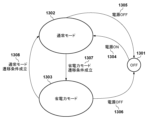
ここで、省電力制御について説明する。図13は、MFP100の運転状態を説明する状態遷移図である。MFP100は電源OFF状態(電源オフ状態)1301、通常モード1302、省電力モード1303を持っており、どれか1つの状態をとる。電源が入っていない状態では、電源OFF状態1301となる。通常モード1302はMFP100が備えるデバイスに通電されている状態である。省電力モード1303では、プリンタ部103、スキャナ部104への給電を止め、操作部102や、コントローラ部101の一部にのみ給電している状態である。省電力モードではMFP100内の限られた部分にのみ給電するため通常モードに比べて大幅に消費電力量を削減できる。
Power saving control Here, power saving control will be described. Fig. 13 is a state transition diagram explaining the operating state of the
電源OFF状態1301で、電源部212に備えられた電源スイッチ(SW)をON(オン)にすると、通常モード1302に遷移する(1304)。
When the power switch (SW) provided on the
通常モード1302で、電源部212に備えられた電源SWをOFF(オフ)にすると電源OFF状態1301に遷移する(1305)。
In
通常モード1302で、省電力モード遷移条件が成立すると省電力モード1303に遷移する(1307)。ここで、省電力モード遷移条件は、操作部102を最後に操作してから一定時間経過したこと、プリンタ部103で印刷を終えてから一定期間経過したことなどがある。このほか、スキャナ部104でスキャンを終えてから一定時間経過したこと、トークン更新処理を終えてから一定時間経過したこと、ネットワークI/F204を介した通信を終えてから一定時間経過したことなどもある。また操作部102により省電力モードへの移行が指示されたことも含まれてよい。
In
省電力モード1303で、電源部212に備えられた電源SWをOFFにすると電源OFF状態1301に遷移する(1306)。省電力モード1303で、通常モード遷移条件が成立すると、通常モードへ遷移する(1308)。
In the
ここで、通常モードへの遷移条件は、操作部102を操作したこと、ネットワークI/F204を経由してクライアント端末150から印刷要求などMFP100がネットワーク経由で公開している機能へのアクセスがあったことを含む。さらに、タイマ制御部512に設定された処理の実行時刻になったことなどを含む。タイマ制御部512に設定された時間に開始される処理には、図12のトークン更新処理が含まれる。
The conditions for transitioning to the normal mode include operating the
また、省電力モードから通常モードに遷移したときに実行する処理の登録を受け付ける。この処理が登録されている場合は、省電力モード1303から通常モード1302に遷移したときに(1308)、この登録された処理を実行する。以上、省電力制御についての概要を説明した。
The system also accepts registration of processes to be executed when the system transitions from power saving mode to normal mode. If such processes are registered, the system executes the registered processes when the system transitions from
●効果
次に本実施形態の発明による消費電力削減効果について説明する。図14は、各アクセストークンの有効期限切れのタイミングでトークン更新処理を実施した、従来の場合についての60分間のシミュレーションを説明するタイムチャート図である。
Effects Next, the power consumption reduction effect of the present embodiment will be described. Fig. 14 is a time chart illustrating a simulation of a 60-minute period for a conventional case in which a token update process is performed when each access token expires.
ここで、省電力モードへの遷移条件がトークン更新処理を終えてから1分後、AAA社電子メールサービスのアクセストークンの有効期間が20分間、BBB社ストレージサービスのアクセストークンの有効期間が30分間とする。図中白抜きの長方形部が通常モードで動作している期間、網掛けの長方形部が省電力モードで動作している期間を表している。 Here, the conditions for transitioning to power saving mode are one minute after the token update process is completed, the validity period of the access token for AAA Company's email service is 20 minutes, and the validity period of the access token for BBB Company's storage service is 30 minutes. In the figure, the open rectangular area represents the period during which the device is operating in normal mode, and the shaded rectangular area represents the period during which the device is operating in power saving mode.
まず。通常モード期間1401の最初にAAA社電子メールサービスとBBB社電子メールサービスのアクセストークンを更新したとする。アクセストークンの更新処理は短時間で終了するため、分オーダでのシミュレーションをする場合は無視しても構わない。従って、2つのアクセストークンを更新してから1分間通常モードで動作する。その後、省電力モード遷移条件が満たされると省電力モードに移行して省電力モード期間1402である19分間省電力モード(スリープモードとも呼ぶ)で動作する。
First, assume that the access tokens for the AAA company email service and the BBB company email service are updated at the beginning of the
次に、AAA社電子メールサービスの有効期限である前回更新から20分後に通常モードに遷移し、AAA社電子メールサービスのアクセストークンの更新を実施し、通常モード期間1403では1分間通常モードで動作する。その後、省電力モードに遷移して省電力モード期間1404では9分間省電力モードで動作する。
Next, 20 minutes after the last update, which is the expiration date of the AAA Company's email service, the device transitions to normal mode, updates the access token for the AAA Company's email service, and operates in normal mode for one minute during
次に、BBB社サービスの有効期限である前回更新から30分後に通常モードに遷移し、AAA社電子メールサービスのアクセストークンの更新を実施し、通常モード期間1405では1分間通常モードで動作する。その後、省電力モードに遷移して省電力モード期間1406では9分間省電力モードで動作する。
Next, 30 minutes after the last update, which is the expiration date for the BBB company service, the device transitions to normal mode, updates the access token for the AAA company email service, and operates in normal mode for one minute during
次に、AAA社電子メールサービスの有効期限である前回更新から20分後に通常モードに遷移し、AAA社電子メールサービスのアクセストークンの更新を実施し、通常モード期間1407では1分間通常モードで動作する。その後、省電力モードに遷移して省電力モード期間1408では19分間省電力モードで動作する。ここまでで開始から60分間となる。
Next, 20 minutes after the last update, which is the expiration date for the AAA Company email service, the device transitions to normal mode, updates the access token for the AAA Company email service, and operates in normal mode for one minute during
このシミュレーションでは、60分間のうち4分間通常モードで動作することになる。 In this simulation, the system will operate in normal mode for 4 minutes out of every 60 minutes.
図15は本実施形態に係る発明に従い、アクセストークンの有効期限のうち最短の期間のタイミングですべてのトークン更新処理を実施した場合についての60分間のシミュレーションを説明するタイムチャート図である。 Figure 15 is a time chart diagram illustrating a 60-minute simulation in which all token update processes are performed at the shortest period of validity of the access token according to the present embodiment of the invention.
ここで、図14と同様、省電力モードへの遷移条件がトークン更新処理を終えてから1分後、AAA社電子メールサービスのアクセストークンの有効期間が20分間、BBB社ストレージサービスのアクセストークンの有効期間が30分間とする。図中白抜きの長方形部が通常モードで動作している期間、網掛けの長方形部が省電力モードで動作している期間を表している。 As in FIG. 14, the conditions for transitioning to power saving mode are one minute after the completion of the token update process, the validity period of the access token for AAA Company's email service is 20 minutes, and the validity period of the access token for BBB Company's storage service is 30 minutes. In the figure, the open rectangular area represents the period during which the device is operating in normal mode, and the shaded rectangular area represents the period during which the device is operating in power saving mode.
まず、通常モード期間1501の最初にAAA社電子メールサービスとBBB社電子メールサービスのアクセストークンを更新したとする。その後、約1分間通常モードで動作する。その後、省電力モード遷移条件が満たされると省電力モードに移行して省電力モード期間1502である19分間、省電力モードで動作する。
First, assume that the access tokens for the AAA company email service and the BBB company email service are updated at the beginning of the
次に、AAA社電子メールサービスの有効期限である前回更新から20分後に通常モードに遷移し、AAA社電子メールサービスのアクセストークンとBBB社ストレージサービスのアクセストークン更新を実施する。その後通常モード期間1503では1分間通常モードで動作する。その後、省電力モードに遷移して省電力モード期間1504では19分間、省電力モードで動作する。
Next, 20 minutes after the last update, which is the expiration date for the AAA Company email service, the device transitions to normal mode, and updates the access token for the AAA Company email service and the access token for the BBB Company storage service. After that, the device operates in normal mode for one minute during
次に、AAA社電子メールサービスの有効期限である前回更新から20分後に通常モードに遷移し、AAA社電子メールサービスのアクセストークンとBBB社ストレージサービスのアクセストークン更新を実施する。その後通常モード期間1505では1分間通常モードで動作する。その後、省電力モードに遷移して省電力モード期間1506では19分間、省電力モードで動作する。ここまでで開始から60分間となる。
Next, 20 minutes after the last update, which is the expiration date for the AAA Company email service, the device transitions to normal mode, and updates the access token for the AAA Company email service and the access token for the BBB Company storage service. After that, the device operates in normal mode for one minute during
このシミュレーションでは、60分間のうち3分間通常モードで動作することになる。図14の従来のタイミングでトークンを更新するシミュレーションに比べて、本実施形態に係る発明のシミュレーションでは通常モードでの動作時間が1分間短くなった。このシミュレーションによれば、60分のうちの1分間の効果であるが、省電力モードへの遷移時間が長い場合や、保持しているアクセストークンが多い場合は効果が拡大する。従って、本実施形態によれば複数のアクセストークンのうち有効期限が最短のものの間隔ですべてのアクセストークンを更新することで省電力モードでの運転時間を延ばすことができる。 In this simulation, the device operates in normal mode for 3 minutes out of 60 minutes. Compared to the simulation in FIG. 14 in which the token is updated at the conventional timing, the simulation of the invention according to this embodiment shortens the operating time in normal mode by 1 minute. According to this simulation, the effect is 1 minute out of 60 minutes, but the effect is greater when the transition time to power saving mode is long or when many access tokens are held. Therefore, according to this embodiment, the operating time in power saving mode can be extended by updating all access tokens at the interval of the one with the shortest expiration date among multiple access tokens.
[変形例]
図6のシーケンス中、ステップ603でデバイス認可応答を受信したMFP100は、例えばユーザコード承認を行うエンドユーザ検証エンドポイントのURLをコード化した二次元バーコードとユーザコードとを含む画面を操作部102に表示してもよい。その場合には、ステップ604でデバイス認可結果画面をクライアント端末150に送信する代わりに、クライアント端末150がMFP100に表示された二次元バーコードを読み取る。そして二次元バーコードをデコードしてエンドユーザ検証エンドポイントのURLを取得し、ステップ607でそこにアクセスしてよい。
[Modification]
6, the
また図6ではユーザコードとユーザ認証とを独立した工程及び画面で行っているが、ステップ608でユーザコードと認証情報の両方の入力画面を認可サーバ110がクライアント端末150に送信してもよい。その場合には、クライアント端末ではその両方を1画面で入力して認可サーバ110に送信してユーザ認証を行ってよい。
In addition, in FIG. 6, the user code and user authentication are performed in separate steps and on separate screens, but in
なお例えば認可サーバ110がMFP100を特定するデバイスコードをユーザコードと紐づけて発行し、MFP1100を介してクライアント端末150に送信しておく。そしてデバイスコードを入力されたユーザコードとともにステップ609でクライアント端末150が認可サーバ110に送信することなどにより、よりユーザの信頼性を高めることができる。
For example, the
[実施形態2]
実施形態1では、図12のトークン更新処理を、トークン更新タイマがタイムアップしたときに開始する例を示した。トークン更新処理の実施タイミングを、トークン更新時間だけでなく、省電力モードから通常モードに遷移したときにも実行する例を説明する。
[Embodiment 2]
In the first embodiment, an example has been shown in which the token update process in Fig. 12 is started when the token update timer times out. An example will be described in which the token update process is executed not only at the token update time but also when the mode is transitioned from the power saving mode to the normal mode.
本実施形態では実施形態1の図10のフローチャートに変わり、図22のフローチャートで説明する処理を実行する。本フローチャートにおける処理はすべてMFP100のトークン処理部511のプログラムをCPU201が実行することで実現される。S1001からS1009の処理は図10と同じである。
In this embodiment, instead of the flowchart in FIG. 10 of the first embodiment, the process described in the flowchart in FIG. 22 is executed. All the processes in this flowchart are realized by the
S1008の後、およびS1010の後でS2201が実行される。S2201で、省電力制御部510に、省電力モードから通常モードに遷移したとき(1308)に実行される処理として、トークン更新処理(図12)を登録する。
After S1008 and after S1010, S2201 is executed. In S2201, the token update process (FIG. 12) is registered in the power saving
これにより、省電力制御部510により省電力モードから通常モードに遷移したとき(1308)にトークン更新処理(図12)が実行される。
As a result, the token update process (Figure 12) is executed when the power saving
本実施形態における省電力効果について説明する。 The power saving effect of this embodiment will be explained.
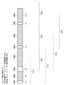
図18は本実施形態に従い、アクセストークンの有効期限のうち最短の期間のタイミング、および、省電力モードから通常モードへの遷移時(1308)に、すべてのトークン更新処理を実施した場合のシミュレーションを説明するタイムチャート図である。シミュレーション時間は60分間である。 Figure 18 is a time chart illustrating a simulation of the present embodiment in which all token update processes are performed at the timing of the shortest period of validity of the access token and at the time of transition from power saving mode to normal mode (1308). The simulation time is 60 minutes.
ここで、図14と同様、省電力モードへの遷移条件がトークン更新処理を終えてから1分後、AAA社電子メールサービスのアクセストークンの有効期間が20分間、BBB社ストレージサービスのアクセストークンの有効期間が30分間とする。図中白抜きの長方形部が通常モードで動作している期間、網掛けの長方形部が省電力モードで動作している期間を表している。 As in FIG. 14, the conditions for transitioning to power saving mode are one minute after the completion of the token update process, the validity period of the access token for AAA Company's email service is 20 minutes, and the validity period of the access token for BBB Company's storage service is 30 minutes. In the figure, the open rectangular area represents the period during which the device is operating in normal mode, and the shaded rectangular area represents the period during which the device is operating in power saving mode.
まず、通常モード期間1801の最初にAAA社電子メールサービスとBBB社電子メールサービスのアクセストークンを更新したとする。その後、約1分間通常モードで動作する。その後、省電力モードに移行し、省電力モード期間間1802で、5分間、省電力モードで動作する。
First, assume that the access tokens for the AAA company email service and the BBB company email service are updated at the beginning of the
ここで、ユーザがMFP100の操作部102を操作してコピー機能を実行し、約2分間で処理を終えたとする。この時ユーザ操作により、省電力モードから通常モードへの遷移するため、トークン更新処理を実行してAAA社電子メールサービスのアクセストークンとBBB社ストレージサービスのアクセストークン更新をする。処理を終えてから1分後に省電力モードに遷移するので、ここでは、通常モード期間1803で、3分間通常モードで動作する。その後、省電力モードに遷移して省電力モード期間1804では19分間、省電力モードで動作する。
Now, assume that the user operates the
次に、AAA社電子メールサービスの有効期限である前回更新から20分後に通常モードに遷移し、AAA社電子メールサービスのアクセストークンとBBB社ストレージサービスのアクセストークン更新を実施する。そしてこのときの通常モード期間1805では1分間通常モードで動作する。その後、省電力モードに遷移して省電力モード期間1806では19分間、省電力モードで動作する。
Next, 20 minutes after the last update, which is the expiration date for the AAA Company email service, the device transitions to normal mode, and updates the access token for the AAA Company email service and the access token for the BBB Company storage service. During this
次に、AAA社電子メールサービスの有効期限である前回更新から20分後に通常モードに遷移し、AAA社電子メールサービスのアクセストークンとBBB社ストレージサービスのアクセストークン更新を実施する。そしてこのときの通常モード期間1807では1分間通常モードで動作する。その後、省電力モードに遷移して省電力モード期間1808では14分間、省電力モードで動作する。ここまでで開始から60分間となる。
Next, 20 minutes after the last update, which is the expiration date for the AAA Company email service, the device transitions to normal mode, and updates the access token for the AAA Company email service and the access token for the BBB Company storage service. During this
このシミュレーションでは、60分間のうち6分間通常モードで動作することになる。ただし、このうちのユーザがコピー機能の利用した期間(通常モード期間1803)が3分間であり、アクセストークン更新だけのために通常モードで動作したのは、実質3分間である。図14のシミュレーションに比べて通常モードでの動作時間が1分間短くなった。このシミュレーションによれば、60分のうちの1分間の効果であるが、省電力モードへの遷移時間が長い場合や、保持しているアクセストークンが多い場合は効果が拡大する。 In this simulation, the device operates in normal mode for 6 minutes out of 60 minutes. However, the user uses the copy function for 3 minutes (normal mode period 1803), so the actual operation time in normal mode for just updating the access token is 3 minutes. The operation time in normal mode is 1 minute shorter than in the simulation in FIG. 14. According to this simulation, the effect is 1 minute out of 60 minutes, but the effect is greater if the transition time to power saving mode is long or if many access tokens are held.
本実施形態によれば複数のアクセストークンのうち有効期限が最短のものの時間間隔で、および、省電力モードから通常モードに遷移したときに、すべてのアクセストークンを更新する。こうすることで省電力モードでの運転時間を延ばすことができる。 According to this embodiment, all access tokens are updated at the time interval of the access token with the shortest validity among the multiple access tokens, and when transitioning from power saving mode to normal mode. This makes it possible to extend the operating time in power saving mode.
[実施形態3]
実施形態1,2ではトークン更新処理(図12)で無条件にすべてのアクセストークンを更新する例を示した。本実施形態では、次回の更新処理実施タイミングまでに有効期限が切れるアクセストークンのみを更新する例を示す。
[Embodiment 3]
In the first and second embodiments, all access tokens are unconditionally updated in the token update process ( FIG. 12 ). In the present embodiment, an example is shown in which only access tokens that will expire by the time the next update process is performed are updated.
本実施形態では実施形態1の図12のフローチャートに変わり、図23のフローチャートで説明する処理を実行する。本フローチャートにおける処理はすべてMFP100のトークン処理部511のプログラムをCPU201が実行することで実現される。
In this embodiment, instead of the flowchart in FIG. 12 of the first embodiment, the process described in the flowchart in FIG. 23 is executed. All the processes in this flowchart are realized by the
S1201からS1210の処理は図12と同じである。 The processing from S1201 to S1210 is the same as in FIG. 12.
S2401では、現在処理対象にしているレコードのアクセストークンの有効期限が、次回トークン更新処理時刻以降かどうかを判定する。次回トークン更新処理時刻とは、現在時刻にS1102でFlashROM210保存した実行タイマ間隔を足した値である。着目トークンの有効期限が次回トークン更新処理時刻以降であれば、トークン更新処理をスキップし、S1207に処理を進め、そうでなければ、S1203に処理を進める。
In S2401, it is determined whether the expiration date of the access token of the record currently being processed is after the next token update processing time. The next token update processing time is the current time plus the execution timer interval saved in
例えば、トークン管理情報が図19に例示したトークン管理情報1900の状態になっており、アクセストークン1111aaaaについて、2022/12/15 13:20:00にトークン更新処理を実行する場合を説明する。ここで、実行タイマ間隔が20分であるので、次回トークン更新処理時刻は2022/12/15 13:40:00となる。
For example, the token management information is in the state of
AAA社電子メールサービスのアクセストークン1111aaaaの有効期限は2022/12/15 13:20:00であるので、S2301で、次回トークン更新処理時刻以降ではないと判定する。また、BBB社ストレージサービスのアクセストークン3333aaaaの有効期限は2022/12/15 13:50:00であるので、S2301で、次回トークン更新処理時刻以降であると判定する。そのため、2022/12/15 13:20:00におけるトークンの更新ではアクセストークン1111aaaaは更新され、アクセストークン3333aaaaは更新されない。 The expiration date of access token 1111aaaa for the AAA Company's email service is 2022/12/15 13:20:00, so in S2301 it is determined that it will not be after the next token update processing time. Also, the expiration date of access token 3333aaaa for the BBB Company's storage service is 2022/12/15 13:50:00, so in S2301 it is determined that it will be after the next token update processing time. Therefore, when the token is updated at 2022/12/15 13:20:00, access token 1111aaaa is updated, but access token 3333aaaa is not updated.
以上説明したように、本実施形態では、トークン更新タイミングで、次回以降のタイミングで更新すればよいトークンの更新を行わないようにすることで、トークン更新時の電力消費量を抑えることができる。また、実施形態1の効果は本実施形態でも損なわれることがない。 As described above, in this embodiment, by not updating the token at the token update timing when it is sufficient to update it at the next or subsequent timing, it is possible to reduce power consumption during token update. Furthermore, the effects of embodiment 1 are not impaired in this embodiment.
さらに実施形態2において、省電力モードから通常モードへ復帰した際に実行されるトークン更新処理を、図12の処理から本実施形態の図23の処理としてもよい。そのようにすることで、実施形態2の効果を損なうことなく、トークン更新時の電力消費量を抑えることができる。 Furthermore, in the second embodiment, the token update process executed when returning from the power saving mode to the normal mode may be changed from the process of FIG. 12 to the process of FIG. 23 of this embodiment. By doing so, it is possible to reduce the amount of power consumption during token update without compromising the effect of the second embodiment.
[その他の実施例]
本発明は、上述の実施形態の1以上の機能を実現するプログラムを、ネットワーク又は記憶媒体を介してシステム又は装置に供給し、そのシステム又は装置のコンピュータにおける1つ以上のプロセッサーがプログラムを読出し実行する処理でも実現可能である。また、1以上の機能を実現する回路(例えば、ASIC)によっても実現可能である。
[Other Examples]
The present invention can also be realized by a process in which a program for implementing one or more of the functions of the above-described embodiments is supplied to a system or device via a network or a storage medium, and one or more processors in a computer of the system or device read and execute the program. The present invention can also be realized by a circuit (e.g., ASIC) that implements one or more of the functions.
●実施形態のまとめ
上記実施形態をまとめると以下のような発明が含まれる。
(項目1)
所定の条件が満たされると通常モードから電力消費量がより少ない省電力モードに遷移する省電力機能を有する情報処理装置であって、
認可サーバと通信するための通信手段と、
制御手段とを有し、
前記制御手段は、
前記認可サーバから、アクセストークンとその有効期限とを取得し、
取得済みのアクセストークンの有効期限を前記アクセストークンと関連付けて保存し、
保存されている前記取得済みのアクセストークンのうちの少なくとも1つのアクセストークンの有効期限に達した場合には、前記省電力モードであれば前記通常モードに復帰して前記取得済みのアクセストークンの少なくとも一部を更新する
ことを特徴とする情報処理装置。
(項目2)
項目1に記載の情報処理装置であって、
前記制御手段は、保存されている前記取得済みのアクセストークンのうちの少なくとも1つのアクセストークンの前記有効期限に達した場合には、前記取得済みのアクセストークンの全てを更新する
ことを特徴とする情報処理装置。
(項目3)
項目1または2に記載の情報処理装置であって、
設定した時間を計測する計測手段を更に有し、
前記制御手段は、
前記アクセストークンを取得または更新した際に、保存された前記取得済みのアクセストークンの有効期限のうち、最も早い有効期限に合わせた時間を前記計測手段に設定し、
前記計測手段により計測された時間が設定した前記時間に達した際に、前記取得済みのアクセストークンの少なくとも一部を更新する
ことを特徴とする情報処理装置。
(項目4)
項目1乃至3のいずれか一項に記載の情報処理装置であって、
前記制御手段はさらに、前記省電力モードから前記通常モードに移行した際にも、前記取得済みのアクセストークンの全てを更新する更新処理を実行する
ことを特徴とする情報処理装置。
(項目5)
項目4に記載の情報処理装置であって、
前記情報処理装置は、前記省電力モードから前記通常モードに移行した際に実行する処理を設定しておく機能を有し、
前記省電力モードから前記通常モードに移行した際に実行する処理として前記更新処理を設定しておくことで、前記省電力モードから前記通常モードに移行した際に、前記取得済みのアクセストークンの全てを更新する
ことを特徴とする情報処理装置。
(項目6)
項目3に記載の情報処理装置であって、
前記制御手段は、保存されている前記取得済みのアクセストークンのうちの少なくとも1つのアクセストークンの前記有効期限に達した場合には、前記取得済みのアクセストークンのうち、次回の更新の時期よりも前記有効期限が早いアクセストークンを更新する
ことを特徴とする情報処理装置。
(項目7)
項目6に記載の情報処理装置であって、
前記次回の更新の時期は、前記有効期限から前記計測手段に設定した前記時間が経過した時期である
ことを特徴とする情報処理装置。
(項目8)
項目1乃至7のいずれか一項に記載の情報処理装置であって、
前記アクセストークンの更新は、前記アクセストークンとともに取得したリフレッシュトークンを前記認可サーバに送信することで行う
ことを特徴とする情報処理装置。
(項目9)
項目1乃至8のいずれか一項に記載の情報処理装置であって、
前記アクセストークンは、ユーザによるユーザ権限の移譲が認可された際に前記認可サーバにより発行される
ことを特徴とする情報処理装置。
Summary of the embodiments The above embodiments can be summarized as follows:
(Item 1)
An information processing device having a power saving function that transitions from a normal mode to a power saving mode in which power consumption is reduced when a predetermined condition is satisfied,
A communication means for communicating with the authorization server;
and a control means,
The control means
Obtaining an access token and its expiration date from the authorization server;
The expiration date of the obtained access token is stored in association with the access token;
An information processing device characterized in that, when the expiration date of at least one of the stored acquired access tokens is reached, if in the power saving mode, the information processing device returns to the normal mode and updates at least some of the acquired access tokens.
(Item 2)
Item 1 is an information processing device according to the present invention,
The information processing device is characterized in that the control means updates all of the acquired access tokens when the expiration date of at least one of the stored access tokens that have been acquired is reached.
(Item 3)
3. The information processing device according to claim 1,
The device further includes a measuring means for measuring a set time,
The control means
When the access token is acquired or updated, a time corresponding to the earliest expiration date among the expiration dates of the acquired and stored access tokens is set in the measurement means;
2. An information processing device comprising: an information processing unit that updates at least a part of the acquired access token when the time measured by the measuring unit reaches the set time.
(Item 4)
4. The information processing device according to any one of claims 1 to 3,
The information processing apparatus is characterized in that the control means further executes an update process for updating all of the acquired access tokens when the information processing apparatus transitions from the power saving mode to the normal mode.
(Item 5)
Item 4. An information processing device according to item 4,
the information processing device has a function of setting a process to be executed when the information processing device transitions from the power saving mode to the normal mode,
An information processing device characterized in that by setting the update process as a process to be executed when transitioning from the power saving mode to the normal mode, all of the acquired access tokens are updated when transitioning from the power saving mode to the normal mode.
(Item 6)
Item 3. The information processing device according to item 3,
The information processing device is characterized in that, when the expiration date of at least one of the acquired access tokens that is stored is reached, the control means updates an access token among the acquired access tokens whose expiration date is earlier than the next renewal date.
(Item 7)
Item 6. An information processing device according to item 6,
The information processing device according to claim 1, wherein the next update time is a time when the time set in the measuring means has elapsed from the expiration date.
(Item 8)
8. The information processing device according to any one of claims 1 to 7,
The information processing device, characterized in that the access token is updated by sending a refresh token acquired together with the access token to the authorization server.
(Item 9)
9. The information processing device according to any one of claims 1 to 8,
The information processing device, wherein the access token is issued by the authorization server when the transfer of user authority by the user is authorized.
本発明は上記実施形態に制限されるものではなく、発明の精神及び範囲から離脱することなく、様々な変更及び変形が可能である。従って、発明の範囲を公にするために請求項を添付する。 The present invention is not limited to the above-described embodiments, and various modifications and variations are possible without departing from the spirit and scope of the invention. Therefore, the following claims are appended to disclose the scope of the invention.
100 MFP、110,130 認可サーバ、120 電子メールサーバ、140 ストレージサーバ、150 クライアント端末 100 MFP, 110, 130 Authorization server, 120 Email server, 140 Storage server, 150 Client terminal
Claims (11)
認可サーバと通信するための通信手段と、
制御手段とを有し、
前記制御手段は、
前記認可サーバから、アクセストークンとその有効期限とを取得し、
取得済みのアクセストークンの有効期限を前記アクセストークンと関連付けて保存し、
保存されている前記取得済みのアクセストークンのうちの少なくとも1つのアクセストークンの有効期限に達した場合には、前記省電力モードであれば前記通常モードに復帰して前記取得済みのアクセストークンの少なくとも一部を更新する
ことを特徴とする情報処理装置。 An information processing device having a power saving function that transitions from a normal mode to a power saving mode in which power consumption is reduced when a predetermined condition is satisfied,
A communication means for communicating with the authorization server;
and a control means,
The control means
Obtaining an access token and its expiration date from the authorization server;
The expiration date of the obtained access token is stored in association with the access token;
An information processing device characterized in that, when the expiration date of at least one of the stored acquired access tokens is reached, if in the power saving mode, the information processing device returns to the normal mode and updates at least some of the acquired access tokens.
前記制御手段は、保存されている前記取得済みのアクセストークンのうちの少なくとも1つのアクセストークンの前記有効期限に達した場合には、前記取得済みのアクセストークンの全てを更新する
ことを特徴とする情報処理装置。 2. The information processing device according to claim 1,
The information processing device is characterized in that the control means updates all of the acquired access tokens when the expiration date of at least one of the stored access tokens that have been acquired is reached.
設定した時間を計測する計測手段を更に有し、
前記制御手段は、
前記アクセストークンを取得または更新した際に、保存された前記取得済みのアクセストークンの有効期限のうち、最も早い有効期限に合わせた時間を前記計測手段に設定し、
前記計測手段により計測された時間が設定した前記時間に達した際に、前記取得済みのアクセストークンの少なくとも一部を更新する
ことを特徴とする情報処理装置。 2. The information processing device according to claim 1,
The device further includes a measuring means for measuring a set time,
The control means
When the access token is acquired or updated, a time corresponding to the earliest expiration date among the expiration dates of the acquired and stored access tokens is set in the measurement means;
2. An information processing device comprising: an information processing unit that updates at least a part of the acquired access token when the time measured by the measuring unit reaches the set time.
前記制御手段はさらに、前記省電力モードから前記通常モードに移行した際にも、前記取得済みのアクセストークンの全てを更新する更新処理を実行する
ことを特徴とする情報処理装置。 2. The information processing device according to claim 1,
The information processing apparatus is characterized in that the control means further executes an update process for updating all of the acquired access tokens when the information processing apparatus transitions from the power saving mode to the normal mode.
前記情報処理装置は、前記省電力モードから前記通常モードに移行した際に実行する処理を設定しておく機能を有し、
前記省電力モードから前記通常モードに移行した際に実行する処理として前記更新処理を設定しておくことで、前記省電力モードから前記通常モードに移行した際に、前記取得済みのアクセストークンの全てを更新する
ことを特徴とする情報処理装置。 5. The information processing device according to claim 4,
the information processing device has a function of setting a process to be executed when the information processing device transitions from the power saving mode to the normal mode,
An information processing device characterized in that by setting the update process as a process to be executed when transitioning from the power saving mode to the normal mode, all of the acquired access tokens are updated when transitioning from the power saving mode to the normal mode.
前記制御手段は、保存されている前記取得済みのアクセストークンのうちの少なくとも1つのアクセストークンの前記有効期限に達した場合には、前記取得済みのアクセストークンのうち、次回の更新の時期よりも前記有効期限が早いアクセストークンを更新する
ことを特徴とする情報処理装置。 4. The information processing device according to claim 3,
The information processing device is characterized in that, when the expiration date of at least one of the acquired access tokens that is stored is reached, the control means updates an access token among the acquired access tokens whose expiration date is earlier than the next renewal date.
前記次回の更新の時期は、前記有効期限から前記計測手段に設定した前記時間が経過した時期である
ことを特徴とする情報処理装置。 7. The information processing device according to claim 6,
The information processing device according to claim 1, wherein the next update time is a time when the time set in the measuring means has elapsed from the expiration date.
前記アクセストークンの更新は、前記アクセストークンとともに取得したリフレッシュトークンを前記認可サーバに送信することで行う
ことを特徴とする情報処理装置。 2. The information processing device according to claim 1,
The information processing device, characterized in that the access token is updated by sending a refresh token acquired together with the access token to the authorization server.
前記アクセストークンは、ユーザによるユーザ権限の移譲が認可された際に前記認可サーバにより発行される
ことを特徴とする情報処理装置。 2. The information processing device according to claim 1,
The information processing device, wherein the access token is issued by the authorization server when the transfer of user authority by the user is authorized.
前記情報処理装置は、認可サーバと通信するための通信手段と、
制御手段とを有し、
前記制御方法は、
前記制御手段が、前記認可サーバから、アクセストークンとその有効期限とを取得し、
前記制御手段が、取得済みのアクセストークンの有効期限を前記アクセストークンと関連付けて保存し、
前記制御手段が、保存されている前記取得済みのアクセストークンのうちの少なくとも1つのアクセストークンの有効期限に達した場合には、前記省電力モードであれば前記通常モードに復帰して前記取得済みのアクセストークンの少なくとも一部を更新する、ことを含む
ことを特徴とする情報処理装置の制御方法。 A method for controlling an information processing device having a power saving function for transitioning from a normal mode to a power saving mode with lower power consumption when a predetermined condition is satisfied, comprising:
The information processing device includes a communication means for communicating with an authorization server;
and a control means,
The control method includes:
The control means acquires an access token and its expiration date from the authorization server,
The control means stores the expiration date of the acquired access token in association with the access token,
A control method for an information processing device, comprising: when the control means receives an expiration date for at least one of the acquired access tokens stored in the information processing device, if the information processing device is in the power saving mode, returning to the normal mode and updating at least a portion of the acquired access tokens.
Priority Applications (2)
| Application Number | Priority Date | Filing Date | Title |
|---|---|---|---|
| JP2023108517A JP2025007244A (en) | 2023-06-30 | 2023-06-30 | Information processing device, control method thereof, and program |
| US18/753,260 US12585802B2 (en) | 2023-06-30 | 2024-06-25 | System and method for updating access tokens in an information processing apparatus |
Applications Claiming Priority (1)
| Application Number | Priority Date | Filing Date | Title |
|---|---|---|---|
| JP2023108517A JP2025007244A (en) | 2023-06-30 | 2023-06-30 | Information processing device, control method thereof, and program |
Publications (1)
| Publication Number | Publication Date |
|---|---|
| JP2025007244A true JP2025007244A (en) | 2025-01-17 |
Family
ID=94126089
Family Applications (1)
| Application Number | Title | Priority Date | Filing Date |
|---|---|---|---|
| JP2023108517A Pending JP2025007244A (en) | 2023-06-30 | 2023-06-30 | Information processing device, control method thereof, and program |
Country Status (2)
| Country | Link |
|---|---|
| US (1) | US12585802B2 (en) |
| JP (1) | JP2025007244A (en) |
Families Citing this family (1)
| Publication number | Priority date | Publication date | Assignee | Title |
|---|---|---|---|---|
| EP4733965A1 (en) * | 2024-10-25 | 2026-04-29 | Sharp Kabushiki Kaisha | Information processing apparatus and method of controlling information processing apparatus |
Family Cites Families (13)
| Publication number | Priority date | Publication date | Assignee | Title |
|---|---|---|---|---|
| JP5209993B2 (en) * | 2008-03-03 | 2013-06-12 | キヤノン株式会社 | Information processing apparatus and control method thereof |
| US8565434B2 (en) * | 2008-05-27 | 2013-10-22 | Qualcomm Incorporated | Methods and systems for maintaining security keys for wireless communication |
| JP5328332B2 (en) * | 2008-12-19 | 2013-10-30 | キヤノン株式会社 | Image processing system, image processing apparatus, and image processing method |
| JP5377009B2 (en) * | 2009-03-13 | 2013-12-25 | キヤノン株式会社 | Information processing apparatus, communication system, information processing apparatus control method, and program |
| JP5748544B2 (en) * | 2011-04-25 | 2015-07-15 | キヤノン株式会社 | Image forming apparatus, control method therefor, and program |
| JP6204786B2 (en) * | 2013-10-11 | 2017-09-27 | キヤノン株式会社 | Printing system, image forming apparatus, control method therefor, and program |
| US9535640B2 (en) * | 2013-12-04 | 2017-01-03 | Fuji Xerox Co., Ltd. | Printing system, information processing apparatus, computer readable medium, and image forming apparatus for providing printing services over a network |
| KR102133755B1 (en) * | 2014-02-19 | 2020-07-15 | 삼성전자주식회사 | A method and apparatus for managing access information for registration of device in a smart home service |
| JP6675163B2 (en) | 2015-07-24 | 2020-04-01 | キヤノン株式会社 | Authority transfer system, control method of authorization server, authorization server and program |
| JP6658628B2 (en) * | 2017-03-13 | 2020-03-04 | 京セラドキュメントソリューションズ株式会社 | Image forming system |
| JP7301669B2 (en) * | 2019-08-07 | 2023-07-03 | キヤノン株式会社 | system, authorization server, control method, program |
| JP7354745B2 (en) * | 2019-10-04 | 2023-10-03 | 富士フイルムビジネスイノベーション株式会社 | Information processing device, information processing system and program |
| GB2609242B (en) * | 2021-07-26 | 2024-07-17 | Dabco Ltd | Waking up a device |
-
2023
- 2023-06-30 JP JP2023108517A patent/JP2025007244A/en active Pending
-
2024
- 2024-06-25 US US18/753,260 patent/US12585802B2/en active Active
Also Published As
| Publication number | Publication date |
|---|---|
| US20250005180A1 (en) | 2025-01-02 |
| US12585802B2 (en) | 2026-03-24 |
Similar Documents
| Publication | Publication Date | Title |
|---|---|---|
| JP4650556B2 (en) | Network equipment | |
| US8805961B2 (en) | Reading device and communication system | |
| US10061931B2 (en) | Image processing apparatus, control method therefor, and computer-readable storage medium storing program for implementing the method | |
| US10205851B2 (en) | Image processing system and image processing apparatus for sending image data | |
| KR102294038B1 (en) | Image forming apparatus using cloud services, image communication method therefor, and storage medium | |
| US10200370B2 (en) | Apparatus, system, and method for authorizing a service | |
| RU2471225C2 (en) | Device for generation of images, system of interaction with device, method of services provision | |
| US10498926B2 (en) | Method and system for a authenticating users in an image processing apparatus and/or image processing system | |
| JP5145254B2 (en) | Image forming system, server apparatus, and image forming apparatus | |
| JP2014073612A (en) | Printing system, printing device and control method thereof, and computer program | |
| JP2010170234A (en) | Image forming system, server device, and image forming device | |
| JP4771298B2 (en) | Image processing apparatus and program | |
| JP4849962B2 (en) | Image processing apparatus, authentication server selection method, and program | |
| US8300255B2 (en) | Printing apparatus, printing system, and method of deleting invalid printing data from storage | |
| JP7143782B2 (en) | Information processing device, data migration system, data migration method, program | |
| JP2025007244A (en) | Information processing device, control method thereof, and program | |
| US12323565B2 (en) | Information processing apparatus, control method, and non-transitory computer-readable storage medium | |
| JP4797925B2 (en) | Information processing program and information processing system | |
| JP2013003933A (en) | Information processor, information management method and information management program | |
| JP2019050529A (en) | Image processing apparatus, processing method thereof, and program | |
| JP2019050530A (en) | Image processing apparatus, processing method thereof, and program | |
| JP2010170232A (en) | Image forming system, server device, and image forming device | |
| US20250247487A1 (en) | Image processing apparatus and control method | |
| US20260030326A1 (en) | Service use application, electronic apparatus, and system | |
| JP2025014560A (en) | Image processing device, control method thereof, and program |