JP2024533893A - Microphone Chip - Google Patents
Microphone Chip Download PDFInfo
- Publication number
- JP2024533893A JP2024533893A JP2022577174A JP2022577174A JP2024533893A JP 2024533893 A JP2024533893 A JP 2024533893A JP 2022577174 A JP2022577174 A JP 2022577174A JP 2022577174 A JP2022577174 A JP 2022577174A JP 2024533893 A JP2024533893 A JP 2024533893A
- Authority
- JP
- Japan
- Prior art keywords
- back plate
- sealing member
- microphone chip
- diaphragm
- inner membrane
- Prior art date
- Legal status (The legal status is an assumption and is not a legal conclusion. Google has not performed a legal analysis and makes no representation as to the accuracy of the status listed.)
- Granted
Links
Images


Classifications
-
- H—ELECTRICITY
- H04—ELECTRIC COMMUNICATION TECHNIQUE
- H04R—LOUDSPEAKERS, MICROPHONES, GRAMOPHONE PICK-UPS OR LIKE ACOUSTIC ELECTROMECHANICAL TRANSDUCERS; ELECTRIC HEARING AIDS; PUBLIC ADDRESS SYSTEMS
- H04R19/00—Electrostatic transducers
- H04R19/005—Electrostatic transducers using semiconductor materials
-
- H—ELECTRICITY
- H04—ELECTRIC COMMUNICATION TECHNIQUE
- H04R—LOUDSPEAKERS, MICROPHONES, GRAMOPHONE PICK-UPS OR LIKE ACOUSTIC ELECTROMECHANICAL TRANSDUCERS; ELECTRIC HEARING AIDS; PUBLIC ADDRESS SYSTEMS
- H04R1/00—Details of transducers, loudspeakers or microphones
- H04R1/02—Casings; Cabinets ; Supports therefor; Mountings therein
- H04R1/04—Structural association of microphone with electric circuitry therefor
-
- H—ELECTRICITY
- H04—ELECTRIC COMMUNICATION TECHNIQUE
- H04R—LOUDSPEAKERS, MICROPHONES, GRAMOPHONE PICK-UPS OR LIKE ACOUSTIC ELECTROMECHANICAL TRANSDUCERS; ELECTRIC HEARING AIDS; PUBLIC ADDRESS SYSTEMS
- H04R1/00—Details of transducers, loudspeakers or microphones
- H04R1/06—Arranging circuit leads; Relieving strain on circuit leads
-
- H—ELECTRICITY
- H04—ELECTRIC COMMUNICATION TECHNIQUE
- H04R—LOUDSPEAKERS, MICROPHONES, GRAMOPHONE PICK-UPS OR LIKE ACOUSTIC ELECTROMECHANICAL TRANSDUCERS; ELECTRIC HEARING AIDS; PUBLIC ADDRESS SYSTEMS
- H04R19/00—Electrostatic transducers
- H04R19/04—Microphones
-
- H—ELECTRICITY
- H04—ELECTRIC COMMUNICATION TECHNIQUE
- H04R—LOUDSPEAKERS, MICROPHONES, GRAMOPHONE PICK-UPS OR LIKE ACOUSTIC ELECTROMECHANICAL TRANSDUCERS; ELECTRIC HEARING AIDS; PUBLIC ADDRESS SYSTEMS
- H04R7/00—Diaphragms for electromechanical transducers; Cones
- H04R7/02—Diaphragms for electromechanical transducers; Cones characterised by the construction
- H04R7/04—Plane diaphragms
- H04R7/06—Plane diaphragms comprising a plurality of sections or layers
-
- H—ELECTRICITY
- H04—ELECTRIC COMMUNICATION TECHNIQUE
- H04R—LOUDSPEAKERS, MICROPHONES, GRAMOPHONE PICK-UPS OR LIKE ACOUSTIC ELECTROMECHANICAL TRANSDUCERS; ELECTRIC HEARING AIDS; PUBLIC ADDRESS SYSTEMS
- H04R7/00—Diaphragms for electromechanical transducers; Cones
- H04R7/16—Mounting or tensioning of diaphragms or cones
- H04R7/18—Mounting or tensioning of diaphragms or cones at the periphery
-
- H—ELECTRICITY
- H04—ELECTRIC COMMUNICATION TECHNIQUE
- H04R—LOUDSPEAKERS, MICROPHONES, GRAMOPHONE PICK-UPS OR LIKE ACOUSTIC ELECTROMECHANICAL TRANSDUCERS; ELECTRIC HEARING AIDS; PUBLIC ADDRESS SYSTEMS
- H04R2201/00—Details of transducers, loudspeakers or microphones covered by H04R1/00 but not provided for in any of its subgroups
- H04R2201/003—Mems transducers or their use
-
- H—ELECTRICITY
- H04—ELECTRIC COMMUNICATION TECHNIQUE
- H04R—LOUDSPEAKERS, MICROPHONES, GRAMOPHONE PICK-UPS OR LIKE ACOUSTIC ELECTROMECHANICAL TRANSDUCERS; ELECTRIC HEARING AIDS; PUBLIC ADDRESS SYSTEMS
- H04R7/00—Diaphragms for electromechanical transducers; Cones
- H04R7/02—Diaphragms for electromechanical transducers; Cones characterised by the construction
- H04R7/04—Plane diaphragms
Landscapes
- Engineering & Computer Science (AREA)
- Physics & Mathematics (AREA)
- Acoustics & Sound (AREA)
- Signal Processing (AREA)
- Multimedia (AREA)
- Electrostatic, Electromagnetic, Magneto- Strictive, And Variable-Resistance Transducers (AREA)
Abstract

【課題】本発明はマイクロフォンチップを提供する。
【解決手段】マイクロフォンチップはフロントチャンバを有するベースと、ベースに設けられてベースに接続されたコンデンサシステムを含み、コンデンサシステムはベースの上部に位置する振動膜と、振動膜と間隔を隔てて設けられたバックプレートを含み、振動膜とバックプレートの間に空気間隔が形成され、振動膜とバックプレートは固定部を介してベースに接続され、振動膜は内膜部、外膜部と支持部を含み、内膜部と外膜部はスリットを介して仕切られ、支持部は固定部に接続され、マイクロフォンチップは、封止部材を更に含み、封止部材はバックプレートに接続され、バックプレートと振動膜の間に位置し、封止部材は内膜部の外周に近接する。振動膜は片持ち状態にある。内膜部は静電気力に誘引して封止部材に吸着され、封止部材は内膜部を支持して動作状態に達し、マイクロフォンの低減衰を低減する。
【選択図】図1
The present invention provides a microphone chip.
[Solution] The microphone chip includes a base having a front chamber, and a capacitor system provided on the base and connected to the base, the capacitor system includes a diaphragm located on the top of the base and a back plate spaced apart from the diaphragm, an air gap is formed between the diaphragm and the back plate, the diaphragm and the back plate are connected to the base through a fixing part, the diaphragm includes an inner membrane part, an outer membrane part and a supporting part, the inner membrane part and the outer membrane part are separated by a slit, the supporting part is connected to the fixing part, the microphone chip further includes a sealing member, the sealing member is connected to the back plate and is located between the back plate and the diaphragm, the sealing member is close to the outer periphery of the inner membrane part. The diaphragm is in a cantilever state. The inner membrane part is attracted to the sealing member by electrostatic force and is adsorbed to the sealing member, and the sealing member supports the inner membrane part to reach an operating state, thereby reducing the low attenuation of the microphone.
[Selected Figure] Figure 1
Description
本発明は、コンデンサ型マイクロフォンの技術分野に関し、特にマイクロフォンチップに関する。 The present invention relates to the technical field of condenser microphones, and in particular to microphone chips.
無線通信の発展に伴い、全世界の携帯電話ユーザーはますます多くなり、携帯電話に対する人々の要求は、通話の実現に留まらず、高品質の通話効果も要求されている。特に現在のモバイルマルチメディア技術の発展に伴い、携帯電話の通話品質は、より重要になる。携帯電話のマイクロフォンは、携帯電話の音声ピックアップ装置として、その設計の良否が通話品質に直接影響を与える。 With the development of wireless communication, the number of mobile phone users around the world is increasing, and people's demands for mobile phones go beyond just being able to make calls; they also demand high-quality call quality. In particular, with the current development of mobile multimedia technology, the quality of mobile phone calls is becoming more and more important. As a voice pickup device for mobile phones, the quality of the design of the mobile phone microphone directly affects the call quality.
現在よく使用されるマイクロフォンとして、主にコンデンサ型マイクロフォン及びMEMS(マイクロモータシステム)マイクロフォンがあり、それらは様々な端末装置に広く応用されている。コンデンサ型マイクロフォンは、振動膜及びバックプレートを含み、両者はMEMS音響センシング容量を構成し、且つMEMS音響センシング容量は、更に接続ディスクを介して処理チップに接続されて音響センシング信号を処理チップに出力して信号処理を行う。従来の技術におけるマイクロフォンのフロントチャンバからバックチャンバまで空気漏れ現象が発生し、マイクロフォンの低減衰を引き起こしやすい。 Currently, the most commonly used microphones are condenser microphones and MEMS (micro-motor system) microphones, which are widely applied to various terminal devices. A condenser microphone includes a diaphragm and a back plate, both of which constitute a MEMS acoustic sensing capacitance, and the MEMS acoustic sensing capacitance is further connected to a processing chip via a connecting disk to output an acoustic sensing signal to the processing chip for signal processing. In the conventional technology, air leakage occurs from the front chamber to the back chamber of the microphone, which is likely to cause low attenuation of the microphone.
本発明は、マイクロフォンの低減衰のリスクを低減するマイクロフォンチップを提供することを目的とする。 The present invention aims to provide a microphone chip that reduces the risk of low microphone attenuation.
本発明は、マイクロフォンチップを提供する。当該マイクロフォンチップは、フロントチャンバを有するベースと、前記ベースに設けられて前記ベースに接続されたコンデンサシステムとを含み、前記コンデンサシステムは、前記ベースの上部に位置する振動膜と、前記振動膜と間隔を隔てて設けられたバックプレートとを含み、前記振動膜と前記バックプレートとの間には、空気間隔が形成され、前記マイクロフォンチップは、固定部を含み、前記振動膜と前記バックプレートとは、前記固定部を介して前記ベースに接続され、
前記振動膜は、内膜部、外膜部及び支持部を含み、前記内膜部と前記外膜部とは、スリットを介して仕切られ、前記支持部は、前記固定部に接続され、
前記マイクロフォンチップは、封止部材を更に含み、前記封止部材は、前記バックプレートに接続され、前記バックプレートと前記振動膜との間に位置し、前記封止部材は、前記内膜部の外周に近接して設けられている。
The present invention provides a microphone chip, the microphone chip including a base having a front chamber, and a capacitor system provided on and connected to the base, the capacitor system including a diaphragm located on the top of the base and a back plate spaced apart from the diaphragm, an air gap being formed between the diaphragm and the back plate, the microphone chip including a fixing part, the diaphragm and the back plate being connected to the base via the fixing part,
The vibration membrane includes an inner membrane portion, an outer membrane portion, and a support portion, the inner membrane portion and the outer membrane portion are partitioned via a slit, and the support portion is connected to the fixed portion,
The microphone chip further includes a sealing member connected to the backplate and positioned between the backplate and the diaphragm, the sealing member being disposed adjacent to an outer periphery of the inner membrane portion.
可能な設計において、前記バックプレートには、排気孔が開設され、前記排気孔は、前記バックプレートにおける、前記封止部材で囲まれた領域内に位置する。 In a possible design, the backplate has exhaust holes formed therein, the exhaust holes being located within the area of the backplate surrounded by the sealing member.
可能な設計において、前記バックプレートには、ガス抜き孔が開設され、前記ガス抜き孔は、前記バックプレートにおける、前記封止部材で囲まれた領域以外の領域に位置する。 In a possible design, the back plate has a gas vent hole that is located in an area of the back plate other than the area surrounded by the sealing member.
可能な設計において、前記支持部は、前記内膜部のエッジに沿って外向き延在し、且つ前記固定部に接続されている。 In a possible design, the support portion extends outward along the edge of the inner membrane portion and is connected to the fixing portion.
可能な設計において、前記支持部は、1つ又は複数設けられている。 In a possible design, one or more of the supports are provided.
可能な設計において、前記マイクロフォンチップは、電極シートを更に含み、前記電極シートは、電極本体及び引き出し部を含み、前記引き出し部は、1つ又は複数ある。 In a possible design, the microphone chip further includes an electrode sheet, the electrode sheet including an electrode body and an extension portion, the extension portion being one or more.
可能な設計において、前記電極シートは、前記バックプレートの前記振動膜に近接する側に設けられ、且つ前記電極本体は、前記封止部材内に位置し、
前記封止部材には、1つ又は複数の切り欠きが設けられ、1つ又は複数の前記引き出し部はそれぞれ、前記切り欠きに沿って外向き延在可能である。
In a possible design, the electrode sheet is provided on a side of the back plate adjacent to the diaphragm, and the electrode body is located within the sealing member;
The sealing member may be provided with one or more cutouts, and the one or more leading portions may each extend outwardly along the cutouts.
可能な設計において、前記マイクロフォンチップの厚さ方向に沿って、前記切り欠きの高さは、前記封止部材の高さに等しい。 In a possible design, the height of the notch along the thickness direction of the microphone chip is equal to the height of the sealing member.
可能な設計において、前記マイクロフォンチップの厚さ方向に沿って、前記切り欠きの高さは、前記封止部材の高さよりも小さく、且つ前記切り欠きは、前記バックプレートに近接して設けられている。 In a possible design, the height of the cutout along the thickness direction of the microphone chip is smaller than the height of the sealing member, and the cutout is located close to the back plate.
可能な設計において、前記電極シートは、前記バックプレートの前記振動膜から離れた側に設けられ、
前記引き出し部は、前記電極本体に沿って外向き延在する。
In a possible design, the electrode sheet is provided on a side of the backplate away from the diaphragm,
The lead portion extends outwardly along the electrode body.
本発明の効果は、以下のとおりである。振動膜を加工することにより、それが内膜部、外膜部と支持部に分けられ、内膜部と外膜部がスリットを介して仕切られ、支持部が固定部に接続されることにより振動膜を固定するため、振動膜が片持ち状態にあり、振動膜材料の応力が十分に放出されることを保証し、振動膜の順応性を向上させる。バックプレートと振動膜との間に封止部材を設けることにより、マイクロフォンが動作する時、内膜部は、静電気力に誘引して封止部材に吸着され、封止部材は、内膜部を支持して動作状態に達するとともに、マイクロフォンの低減衰を低減することができる。 The effects of the present invention are as follows: By processing the diaphragm, it is divided into an inner membrane part, an outer membrane part and a support part, the inner membrane part and the outer membrane part are partitioned through a slit, and the support part is connected to the fixing part to fix the diaphragm, so that the diaphragm is in a cantilever state, which ensures that the stress of the diaphragm material is fully released and improves the adaptability of the diaphragm. By providing a sealing member between the back plate and the diaphragm, when the microphone is operating, the inner membrane part is attracted by electrostatic force and adsorbed to the sealing member, and the sealing member supports the inner membrane part to reach an operating state and can reduce the low attenuation of the microphone.
以下、図面及び実施形態を参照しながら、本発明を更に説明する。 The present invention will be further described below with reference to the drawings and embodiments.
本実施例は、マイクロフォンチップ1を提供し、マイクロフォンの低減衰のリスクを低減することを目的とする。 The present embodiment aims to provide a microphone chip 1 that reduces the risk of low microphone attenuation.
具体的には、図1及び図5に示すように、マイクロフォンチップ1は、フロントチャンバ111を有するベース11と、ベース11に設けられてベース11に接続されたコンデンサシステムとを含み、コンデンサシステムは、ベース11の上部に位置する振動膜12と、振動膜12と間隔を隔てて設けられたバックプレート13とを含み、振動膜12とバックプレート13との間に空気間隔が形成される。外部音声がフロントチャンバ111を介して振動膜12に伝達されると、振動膜12は、外部音圧を感じて振動を発生し、振動膜12とバックプレート13との間の距離を変化させて容量変化を生成し、音声信号から電気信号への変換を実現する。
Specifically, as shown in FIG. 1 and FIG. 5, the microphone chip 1 includes a
マイクロフォンチップ1は、固定部14を含み、振動膜12とバックプレート13は、固定部14を介してベース11に接続されている。振動膜12は、内膜部121、外膜部122及び支持部123を含み、内膜部121と外膜部122とは、スリットを介して仕切られ、支持部123は、固定部14に接続されている。具体的には、振動膜12を加工することにより振動膜12が内膜部121、外膜部122及び支持部123を形成し、外膜部122が内膜部121を囲んで設けられ、内膜部121と外膜部122とは、スリットを介して仕切られ、支持部123は、固定部14に接続されることにより振動膜12を固定し、それにより振動膜12が片持ち状態にあり、振動膜材料の応力が十分に解放されることを保証し、振動膜の順応性を向上させる。
The microphone chip 1 includes a
図1及び図5に示すように、マイクロフォンチップ1は、封止部材15を更に含み、封止部材15は、バックプレート13に接続され、バックプレート13と振動膜12との間に位置し、封止部材15は、内膜部121の外周に近接して設けられ、動作状態にある時、内膜部121は、封止部材15に吸着することができる。バックプレート13には、排気孔131が開設され、排気孔131は、音を伝導し、音圧をバランスさせるために用いられ、排気孔131は、バックプレート13における、封止部材15で囲まれた領域内に位置する。
As shown in FIG. 1 and FIG. 5, the microphone chip 1 further includes a
本実施例において、封止部材15は、一定の高さを有し、マイクロフォンが動作しない時、振動膜12とバックプレート13及び封止部材15は、分離状態にある。マイクロフォンが動作する時、バイアス電圧で、内膜部121は、静電気力に誘引して封止部材15に吸着される。排気孔131をバックプレート13における封止部材15で囲まれた領域内に設けることにより、すなわち、封止部材15を境界にして、バックプレート13は、封止部材15からバックプレート13のエッジ部までの間に排気孔131を完全に設けず、内膜部121を封止部材15に吸着する時、内膜部121とバックプレート13とは、密閉空間を形成し、フロントチャンバ111と内膜部121とバックプレート13との連通を遮断し、封止部材15は、内膜部121を支持して動作状態に達するとともに、マイクロフォンの低減衰のリスクを低減する。
In this embodiment, the sealing
いくつかの実施例において、バックプレート13における、封止部材15で囲まれた領域以外の領域に一定の数のガス抜き孔(図示せず)が設けられてもよい。即ち、封止部材15を境界にして、バックプレート13は、封止部材15からバックプレート13のエッジ部までの間にガス抜き孔を設けることができ、当該範囲内のガス抜き孔の数は、ニーズに応じて設定可能とすることにより、マイクロフォンの低減衰値を調整してもよい。
In some embodiments, a certain number of gas vent holes (not shown) may be provided in the
図2に示すように、支持部123は、内膜部121のエッジに沿って外向き延在し、且つ固定部14に接続されている。支持部123を設けることにより内膜部121を固定し、内膜部121は、片持ち状態にあることにより、振動膜12の応力を解放し、振動膜の順応性を向上させる。
As shown in FIG. 2, the support portion 123 extends outward along the edge of the
ここで、支持部123は、1つ設けられる。すなわち、振動膜12は、単一アームで接続して固定することができ、振動膜12の応力が解放されることを保証し、振動膜の順応性を向上させる。又は、振動膜12は、設置需要に応じて2つ、3つ等の複数の支持部123を設けてもよく、ここで具体的に限定しない。
Here, one support part 123 is provided. That is, the
更に、図3及び図4に示すように、マイクロフォンチップ1は、電極シート16を更に含み、電極シート16は、バックプレート13の振動膜12に接近する側に設けられ、且つ電極シート16は、封止部材15内に位置する。電極シート16は、封止部材15の内側に設けられるため、電極シート16は、封止部材15により遮断され、引き出すことができない。そこで、本実施例において、封止部材15には、切り欠き151が設けられ、電極シート16は、接続された電極本体161及び引き出し部162を含み、引き出し部162は、1つ又は複数あり、引き出し部162は、切り欠き151に沿って外向き延在可能である。このように、電極シート16を切り欠き151に沿って外向きに引き出すことは、実現される。本実施例では、切り欠き151の数について具体的な限定を行わず、引き出し部の数のニーズに応じて1つ、2つ、3つ等設けることができる。
Furthermore, as shown in FIG. 3 and FIG. 4, the microphone chip 1 further includes an
ここで、図4に示すように、マイクロフォンチップ1の厚さ方向に沿って、切り欠き151の高さは、封止部材15の高さに等しいものとすることができる。又は、マイクロフォンチップ1の厚さ方向に沿って、切り欠き151の高さは、封止部材15の高さよりも小さく、すなわち切り欠き151の高さは、電極シート16の高さとマッチングすればよい。且つ、切り欠き151は、バックプレート13に近接して設けられている。このように、振動膜12が封止部材15に吸着された場合に、封止部材15上の切り欠き151によって振動膜12と封止部材15との間に隙間が発生することは、回避される。
Here, as shown in FIG. 4, the height of the
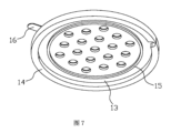
また、図5~図7に示すように、電極シート16は、バックプレート13の振動膜12から離れた側に設けられ、電極シート16は、接続された電極本体161及び引き出し部162を含み、引き出し部162は、電極本体161に沿って外向き延在する。このように、電極シート16を引き出すことは、実現される。
Also, as shown in Figures 5 to 7, the
以上は本発明の実施形態に過ぎず、当業者であれば本発明の思想を逸脱することなく改良を加えることができるが、これらは全て本発明の保護範囲に含まれる。 The above is merely an embodiment of the present invention, and those skilled in the art may make improvements without departing from the spirit of the present invention, all of which are within the scope of protection of the present invention.
1 マイクロフォンチップ
11 ベース
111 フロントチャンバ
12 振動膜
121 内膜部
122 外膜部
123 支持部
13 バックプレート
131 排気孔
14 固定部
15 封止部材
151 切り欠き
16 電極シート
161 電極本体
162 引き出し部
REFERENCE SIGNS LIST 1
Claims (10)
前記マイクロフォンチップは、固定部を含み、前記振動膜と前記バックプレートとは、前記固定部を介して前記ベースに接続され、
前記振動膜は、内膜部、外膜部及び支持部を含み、前記内膜部と前記外膜部とは、スリットを介して仕切られ、前記支持部は、前記固定部に接続され、
前記マイクロフォンチップは、封止部材を更に含み、前記封止部材は、前記バックプレートに接続され、前記バックプレートと前記振動膜との間に位置し、前記封止部材は、前記内膜部の外周に近接して設けられていることを特徴とするマイクロフォンチップ。 A microphone chip including a base having a front chamber, and a capacitor system provided on and connected to the base, the capacitor system including a diaphragm located on an upper portion of the base, and a back plate provided at a distance from the diaphragm, and an air gap is formed between the diaphragm and the back plate,
the microphone chip includes a fixing portion, the diaphragm and the back plate are connected to the base via the fixing portion,
The vibration membrane includes an inner membrane portion, an outer membrane portion, and a support portion, the inner membrane portion and the outer membrane portion are partitioned via a slit, and the support portion is connected to the fixed portion,
The microphone chip further includes a sealing member, the sealing member being connected to the back plate and positioned between the back plate and the diaphragm, the sealing member being provided adjacent to an outer periphery of the inner membrane portion.
前記封止部材には、1つ又は複数の切り欠きが設けられ、1つ又は複数の前記引き出し部はそれぞれ、前記切り欠きに沿って外向き延在可能であることを特徴とする請求項6に記載のマイクロフォンチップ。 the electrode sheet is provided on a side of the back plate that is close to the vibration membrane, and the electrode body is located within the sealing member;
The microphone chip of claim 6, wherein the sealing member is provided with one or more cutouts, and the one or more leading portions are each extendable outwardly along the cutouts.
前記引き出し部は、前記電極本体に沿って外向き延在することを特徴とする請求項6に記載のマイクロフォンチップ。 the electrode sheet is provided on a side of the back plate away from the vibration membrane,
The microphone chip of claim 6 , wherein the lead portion extends outwardly along the electrode body.
Applications Claiming Priority (3)
| Application Number | Priority Date | Filing Date | Title |
|---|---|---|---|
| CN202222257737.4U CN218772429U (en) | 2022-08-25 | 2022-08-25 | microphone chip |
| CN202222257737.4 | 2022-08-25 | ||
| PCT/CN2022/119299 WO2024040649A1 (en) | 2022-08-25 | 2022-09-16 | Microphone chip |
Publications (2)
| Publication Number | Publication Date |
|---|---|
| JP7545496B1 JP7545496B1 (en) | 2024-09-04 |
| JP2024533893A true JP2024533893A (en) | 2024-09-13 |
Family
ID=89996147
Family Applications (1)
| Application Number | Title | Priority Date | Filing Date |
|---|---|---|---|
| JP2022577174A Active JP7545496B1 (en) | 2022-08-25 | 2022-09-16 | Microphone Chip |
Country Status (2)
| Country | Link |
|---|---|
| US (1) | US12267649B2 (en) |
| JP (1) | JP7545496B1 (en) |
Citations (6)
| Publication number | Priority date | Publication date | Assignee | Title |
|---|---|---|---|---|
| US20060280319A1 (en) * | 2005-06-08 | 2006-12-14 | General Mems Corporation | Micromachined Capacitive Microphone |
| US20110216922A1 (en) * | 2010-03-08 | 2011-09-08 | Hai-Feng Li | Silicon condenser microphone |
| JP2013251773A (en) * | 2012-05-31 | 2013-12-12 | Omron Corp | Capacitance type sensor, acoustic sensor, and microphone |
| CN107484051A (en) * | 2017-09-29 | 2017-12-15 | 瑞声声学科技(深圳)有限公司 | MEMS microphone |
| US20190238998A1 (en) * | 2018-01-31 | 2019-08-01 | Aac Acoustic Technologies (Shenzhen) Co., Ltd. | Microphone |
| CN114885264A (en) * | 2022-07-11 | 2022-08-09 | 苏州敏芯微电子技术股份有限公司 | Microphone assembly and electronic equipment |
-
2022
- 2022-09-16 JP JP2022577174A patent/JP7545496B1/en active Active
- 2022-11-30 US US18/072,661 patent/US12267649B2/en active Active
Patent Citations (6)
| Publication number | Priority date | Publication date | Assignee | Title |
|---|---|---|---|---|
| US20060280319A1 (en) * | 2005-06-08 | 2006-12-14 | General Mems Corporation | Micromachined Capacitive Microphone |
| US20110216922A1 (en) * | 2010-03-08 | 2011-09-08 | Hai-Feng Li | Silicon condenser microphone |
| JP2013251773A (en) * | 2012-05-31 | 2013-12-12 | Omron Corp | Capacitance type sensor, acoustic sensor, and microphone |
| CN107484051A (en) * | 2017-09-29 | 2017-12-15 | 瑞声声学科技(深圳)有限公司 | MEMS microphone |
| US20190238998A1 (en) * | 2018-01-31 | 2019-08-01 | Aac Acoustic Technologies (Shenzhen) Co., Ltd. | Microphone |
| CN114885264A (en) * | 2022-07-11 | 2022-08-09 | 苏州敏芯微电子技术股份有限公司 | Microphone assembly and electronic equipment |
Also Published As
| Publication number | Publication date |
|---|---|
| US20240073625A1 (en) | 2024-02-29 |
| JP7545496B1 (en) | 2024-09-04 |
| US12267649B2 (en) | 2025-04-01 |
Similar Documents
| Publication | Publication Date | Title |
|---|---|---|
| CN107409259B (en) | Electronic audio conversion device | |
| WO2010150942A1 (en) | Multifunctional micro speaker | |
| CN114885264B (en) | Microphone assembly and electronic equipment | |
| CN217363312U (en) | MEMS microphone | |
| CN112291691A (en) | MEMS piezoelectric micro-speaker, micro-speaker unit and electronic device | |
| JP7545496B1 (en) | Microphone Chip | |
| TW202147867A (en) | Silicon-based microphone apparatus and electronic device | |
| CN211959548U (en) | Large-amplitude micro loudspeaker | |
| CN218387805U (en) | Microphone chip and microphone | |
| CN218772429U (en) | microphone chip | |
| JP4276108B2 (en) | Microphone unit mounting structure, electronic device including the same, and microphone unit mounting method | |
| JP7627707B1 (en) | Microphone Chip and Microphone | |
| CN112689229B (en) | Silicon-based microphone and manufacturing method thereof | |
| CN214481258U (en) | Micro-electro-mechanical system die | |
| CN114513730B (en) | Microphone assembly and electronic equipment | |
| US11516569B1 (en) | Capacitive microphone | |
| CN112702684B (en) | Silicon-based microphone and manufacturing method thereof | |
| CN207911008U (en) | Mems microphone | |
| CN112118522B (en) | MEMS microphone | |
| CN219659911U (en) | MEMS microphone | |
| JP2023530650A (en) | Silicon-based microphone devices and electronics | |
| CN218959124U (en) | MEMS microphone | |
| CN222366361U (en) | Noise-cancelling microphone | |
| CN223182293U (en) | A speaker module | |
| US12330931B2 (en) | MEMS microphone |
Legal Events
| Date | Code | Title | Description |
|---|---|---|---|
| A621 | Written request for application examination |
Free format text: JAPANESE INTERMEDIATE CODE: A621 Effective date: 20221214 |
|
| A871 | Explanation of circumstances concerning accelerated examination |
Free format text: JAPANESE INTERMEDIATE CODE: A871 Effective date: 20230824 |
|
| TRDD | Decision of grant or rejection written | ||
| A01 | Written decision to grant a patent or to grant a registration (utility model) |
Free format text: JAPANESE INTERMEDIATE CODE: A01 Effective date: 20240820 |
|
| A61 | First payment of annual fees (during grant procedure) |
Free format text: JAPANESE INTERMEDIATE CODE: A61 Effective date: 20240823 |
|
| R150 | Certificate of patent or registration of utility model |
Ref document number: 7545496 Country of ref document: JP Free format text: JAPANESE INTERMEDIATE CODE: R150 |