JP2024137172A - Battery pack - Google Patents
Battery pack Download PDFInfo
- Publication number
- JP2024137172A JP2024137172A JP2023048585A JP2023048585A JP2024137172A JP 2024137172 A JP2024137172 A JP 2024137172A JP 2023048585 A JP2023048585 A JP 2023048585A JP 2023048585 A JP2023048585 A JP 2023048585A JP 2024137172 A JP2024137172 A JP 2024137172A
- Authority
- JP
- Japan
- Prior art keywords
- fixing portion
- battery
- junction box
- battery module
- module
- Prior art date
- Legal status (The legal status is an assumption and is not a legal conclusion. Google has not performed a legal analysis and makes no representation as to the accuracy of the status listed.)
- Granted
Links
Images


Classifications
-
- H—ELECTRICITY
- H01—ELECTRIC ELEMENTS
- H01M—PROCESSES OR MEANS, e.g. BATTERIES, FOR THE DIRECT CONVERSION OF CHEMICAL ENERGY INTO ELECTRICAL ENERGY
- H01M50/00—Constructional details or processes of manufacture of the non-active parts of electrochemical cells other than fuel cells, e.g. hybrid cells
- H01M50/20—Mountings; Secondary casings or frames; Racks, modules or packs; Suspension devices; Shock absorbers; Transport or carrying devices; Holders
- H01M50/244—Secondary casings; Racks; Suspension devices; Carrying devices; Holders characterised by their mounting method
-
- H—ELECTRICITY
- H01—ELECTRIC ELEMENTS
- H01M—PROCESSES OR MEANS, e.g. BATTERIES, FOR THE DIRECT CONVERSION OF CHEMICAL ENERGY INTO ELECTRICAL ENERGY
- H01M10/00—Secondary cells; Manufacture thereof
- H01M10/42—Methods or arrangements for servicing or maintenance of secondary cells or secondary half-cells
- H01M10/425—Structural combination with electronic components, e.g. electronic circuits integrated to the outside of the casing
-
- H—ELECTRICITY
- H01—ELECTRIC ELEMENTS
- H01M—PROCESSES OR MEANS, e.g. BATTERIES, FOR THE DIRECT CONVERSION OF CHEMICAL ENERGY INTO ELECTRICAL ENERGY
- H01M50/00—Constructional details or processes of manufacture of the non-active parts of electrochemical cells other than fuel cells, e.g. hybrid cells
- H01M50/20—Mountings; Secondary casings or frames; Racks, modules or packs; Suspension devices; Shock absorbers; Transport or carrying devices; Holders
- H01M50/204—Racks, modules or packs for multiple batteries or multiple cells
- H01M50/207—Racks, modules or packs for multiple batteries or multiple cells characterised by their shape
- H01M50/209—Racks, modules or packs for multiple batteries or multiple cells characterised by their shape adapted for prismatic or rectangular cells
-
- H—ELECTRICITY
- H01—ELECTRIC ELEMENTS
- H01M—PROCESSES OR MEANS, e.g. BATTERIES, FOR THE DIRECT CONVERSION OF CHEMICAL ENERGY INTO ELECTRICAL ENERGY
- H01M50/00—Constructional details or processes of manufacture of the non-active parts of electrochemical cells other than fuel cells, e.g. hybrid cells
- H01M50/20—Mountings; Secondary casings or frames; Racks, modules or packs; Suspension devices; Shock absorbers; Transport or carrying devices; Holders
- H01M50/204—Racks, modules or packs for multiple batteries or multiple cells
- H01M50/207—Racks, modules or packs for multiple batteries or multiple cells characterised by their shape
- H01M50/211—Racks, modules or packs for multiple batteries or multiple cells characterised by their shape adapted for pouch cells
-
- H—ELECTRICITY
- H01—ELECTRIC ELEMENTS
- H01M—PROCESSES OR MEANS, e.g. BATTERIES, FOR THE DIRECT CONVERSION OF CHEMICAL ENERGY INTO ELECTRICAL ENERGY
- H01M50/00—Constructional details or processes of manufacture of the non-active parts of electrochemical cells other than fuel cells, e.g. hybrid cells
- H01M50/20—Mountings; Secondary casings or frames; Racks, modules or packs; Suspension devices; Shock absorbers; Transport or carrying devices; Holders
- H01M50/233—Mountings; Secondary casings or frames; Racks, modules or packs; Suspension devices; Shock absorbers; Transport or carrying devices; Holders characterised by physical properties of casings or racks, e.g. dimensions
- H01M50/242—Mountings; Secondary casings or frames; Racks, modules or packs; Suspension devices; Shock absorbers; Transport or carrying devices; Holders characterised by physical properties of casings or racks, e.g. dimensions adapted for protecting batteries against vibrations, collision impact or swelling
-
- H—ELECTRICITY
- H01—ELECTRIC ELEMENTS
- H01M—PROCESSES OR MEANS, e.g. BATTERIES, FOR THE DIRECT CONVERSION OF CHEMICAL ENERGY INTO ELECTRICAL ENERGY
- H01M50/00—Constructional details or processes of manufacture of the non-active parts of electrochemical cells other than fuel cells, e.g. hybrid cells
- H01M50/20—Mountings; Secondary casings or frames; Racks, modules or packs; Suspension devices; Shock absorbers; Transport or carrying devices; Holders
- H01M50/249—Mountings; Secondary casings or frames; Racks, modules or packs; Suspension devices; Shock absorbers; Transport or carrying devices; Holders specially adapted for aircraft or vehicles, e.g. cars or trains
-
- H—ELECTRICITY
- H01—ELECTRIC ELEMENTS
- H01M—PROCESSES OR MEANS, e.g. BATTERIES, FOR THE DIRECT CONVERSION OF CHEMICAL ENERGY INTO ELECTRICAL ENERGY
- H01M50/00—Constructional details or processes of manufacture of the non-active parts of electrochemical cells other than fuel cells, e.g. hybrid cells
- H01M50/20—Mountings; Secondary casings or frames; Racks, modules or packs; Suspension devices; Shock absorbers; Transport or carrying devices; Holders
- H01M50/262—Mountings; Secondary casings or frames; Racks, modules or packs; Suspension devices; Shock absorbers; Transport or carrying devices; Holders with fastening means, e.g. locks
-
- H—ELECTRICITY
- H01—ELECTRIC ELEMENTS
- H01M—PROCESSES OR MEANS, e.g. BATTERIES, FOR THE DIRECT CONVERSION OF CHEMICAL ENERGY INTO ELECTRICAL ENERGY
- H01M50/00—Constructional details or processes of manufacture of the non-active parts of electrochemical cells other than fuel cells, e.g. hybrid cells
- H01M50/20—Mountings; Secondary casings or frames; Racks, modules or packs; Suspension devices; Shock absorbers; Transport or carrying devices; Holders
- H01M50/289—Mountings; Secondary casings or frames; Racks, modules or packs; Suspension devices; Shock absorbers; Transport or carrying devices; Holders characterised by spacing elements or positioning means within frames, racks or packs
-
- H—ELECTRICITY
- H01—ELECTRIC ELEMENTS
- H01M—PROCESSES OR MEANS, e.g. BATTERIES, FOR THE DIRECT CONVERSION OF CHEMICAL ENERGY INTO ELECTRICAL ENERGY
- H01M2220/00—Batteries for particular applications
- H01M2220/20—Batteries in motive systems, e.g. vehicle, ship, plane
-
- Y—GENERAL TAGGING OF NEW TECHNOLOGICAL DEVELOPMENTS; GENERAL TAGGING OF CROSS-SECTIONAL TECHNOLOGIES SPANNING OVER SEVERAL SECTIONS OF THE IPC; TECHNICAL SUBJECTS COVERED BY FORMER USPC CROSS-REFERENCE ART COLLECTIONS [XRACs] AND DIGESTS
- Y02—TECHNOLOGIES OR APPLICATIONS FOR MITIGATION OR ADAPTATION AGAINST CLIMATE CHANGE
- Y02E—REDUCTION OF GREENHOUSE GAS [GHG] EMISSIONS, RELATED TO ENERGY GENERATION, TRANSMISSION OR DISTRIBUTION
- Y02E60/00—Enabling technologies; Technologies with a potential or indirect contribution to GHG emissions mitigation
- Y02E60/10—Energy storage using batteries
Landscapes
- Chemical & Material Sciences (AREA)
- Chemical Kinetics & Catalysis (AREA)
- Electrochemistry (AREA)
- General Chemical & Material Sciences (AREA)
- Engineering & Computer Science (AREA)
- Microelectronics & Electronic Packaging (AREA)
- Manufacturing & Machinery (AREA)
- Aviation & Aerospace Engineering (AREA)
- Battery Mounting, Suspending (AREA)
- Arrangement Or Mounting Of Propulsion Units For Vehicles (AREA)
Abstract
Description
本発明は、車両等の移動体に搭載可能なバッテリパックに関する。 The present invention relates to a battery pack that can be mounted on a moving object such as a vehicle.
近年、低炭素社会又は脱炭素社会の実現に向けた取り組みが活発化し、車両においてもCO2排出量の削減やエネルギー効率の改善のために、電動化技術に関する研究開発が行われている。 In recent years, efforts to realize a low-carbon or carbon-free society have become more active, and research and development into electrification technology is being conducted to reduce CO2 emissions and improve energy efficiency in vehicles.
電動化技術ではバッテリが重要な役割を担っている。電動車両には、バッテリを収容したバッテリパックが搭載される。バッテリパックには、バッテリモジュールに加えて、導電部材、ヒューズ、コンタクト等の電子部品が配置されたジャンクションボックスもあわせて収容される。 Batteries play an important role in electrification technology. Electric vehicles are equipped with a battery pack that contains the battery. In addition to the battery module, the battery pack also contains a junction box in which electronic components such as conductive members, fuses, and contacts are arranged.
例えば、特許文献1に記載のバッテリパックでは、バッテリモジュールの上方に架設されるアッパデッキにジャンクションボックスを搭載することが記載されている。 For example, the battery pack described in Patent Document 1 is described as having a junction box mounted on an upper deck that is erected above the battery module.
ところで、近年では、車両の航続距離を延ばすためにより大型のバッテリが搭載される傾向にあり、特定の周波数において、バッテリの振動が大きくなる虞がある。特に、ジャンクションボックスの搭載方法によっては、特定の周波数におけるバッテリの振動が大きくなる虞がある。 In recent years, there has been a trend toward larger batteries being installed in vehicles to increase their driving range, and this can lead to increased battery vibration at certain frequencies. In particular, depending on how the junction box is installed, there is a risk that the vibration of the battery at certain frequencies can become greater.
本発明は、特定の周波数における振動を抑制可能なバッテリパックを提供する。 The present invention provides a battery pack that can suppress vibrations at specific frequencies.
本発明は、
複数のセルが積層されたバッテリモジュールと、
前記バッテリモジュールをモジュール固定部で固定するバッテリケースと、
車両の前後方向に延設され、前記バッテリモジュールの上方に架設されるフレーム部材と、
前記フレーム部材上に配置されるジャンクションボックスと、を備え、前記車両に搭載されるバッテリパックであって、
前記フレーム部材は、前記ジャンクションボックスの前方に位置する第1固定部と、前記ジャンクションボックスの後方に位置する第2固定部とで、前記バッテリケース又は前記バッテリモジュールに固定され、
前記ジャンクションボックスは、前記第1固定部と前記第2固定部との間に位置する中間固定部で、前記バッテリモジュール及び前記バッテリケースには固定されず、前記フレーム部材に固定され、
前記モジュール固定部、前記第1固定部、及び前記第2固定部は、弾性部材を介さない剛結合で固定され、
前記中間固定部は、弾性部材を介して弾性結合で固定されている。
The present invention relates to
A battery module in which a plurality of cells are stacked;
a battery case that fixes the battery module at a module fixing portion;
A frame member extending in the front-rear direction of the vehicle and installed above the battery module;
a junction box disposed on the frame member,
the frame member is fixed to the battery case or the battery module by a first fixing portion located in front of the junction box and a second fixing portion located in the rear of the junction box,
the junction box is an intermediate fixing portion located between the first fixing portion and the second fixing portion, and is not fixed to the battery module or the battery case but is fixed to the frame member;
the module fixing portion, the first fixing portion, and the second fixing portion are rigidly fixed to each other without using an elastic member;
The intermediate fixing portion is fixed by elastic coupling via an elastic member.
本発明によれば、特定の周波数においてバッテリパックの振動を抑えることができる。 The present invention makes it possible to suppress vibrations of the battery pack at specific frequencies.
以下、本発明の一実施形態のバッテリパックについて、添付図面に基づいて説明する。 The battery pack of one embodiment of the present invention will be described below with reference to the attached drawings.
本発明の一実施形態のバッテリパック1は、ハイブリッド車両、電気自動車、燃料電池車等の電動車両に搭載可能に構成される。バッテリパック1は、図1に示すように、4つのバッテリモジュール10と、ジャンクションボックス11と、補器12と、これらを収容するバッテリケース31と、を備える。4つのバッテリモジュール10は、前後方向に2列、左右方向に2列に配置されている。なお、バッテリモジュール10は、2つ以上であればその数は任意に設定することができ、配置も特に限定されるものではない。
The battery pack 1 of one embodiment of the present invention is configured to be mountable on an electric vehicle such as a hybrid vehicle, an electric vehicle, or a fuel cell vehicle. As shown in FIG. 1, the battery pack 1 includes four
バッテリモジュール10は、不図示の電気接続部材を介して互いに電気的に接続されている。バッテリモジュール10が蓄える電力は、車両の駆動源となるモータ等に供給される。なお、以下の説明では、4つのバッテリモジュール10をまとめてバッテリと称することがある。補器12、ジャンクションボックス11、バッテリモジュール10の重量は、この順に大きい。
The
バッテリモジュール10は、図2に示すように、セル21が複数積層されたセル積層体20と、中間プレート30と、一対のエンドプレート37と、一対の拘束部材38と、一対のカバープレート60と、を備える。
As shown in FIG. 2, the
セル積層体20は、複数のセル21が左右方向に積層されて構成される。中間プレート30は、複数のセル21の積層方向(ここでは左右方向)における中間部に設けられている。中間プレート30は、2つ以上設けられてもよい。一対のエンドプレート37は、複数のセル21の積層方向における両端部に設けられている。一対の拘束部材38は、上下方向において互いに対向し、一対のエンドプレート37に連結されて複数のセル21を拘束する。一対のカバープレート60は、前後方向において複数のセル21よりも外側に設けられ、積層方向に延在している。カバープレート60は、前後方向において互いに対向して2つ設けられており、一対のエンドプレート37の前端部又は後端部に固定されてバッテリモジュール10の前面又は後面を形成している。カバープレート60は、前後方向から見たとき、電気絶縁性を有するバスバーカバー23を介して、セル21の電極タブ212同士を接続するバスバー22及びセル21の電極タブ212を覆い、バスバー22及び電極タブ212を保護する。カバープレート60には、電気端子が取り付けられていない。
The cell stack 20 is formed by stacking a plurality of cells 21 in the left-right direction. The
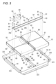
図3も参照して、カバープレート60には、左右に上下方向に貫通する貫通穴61が設けられている。バッテリモジュール10は、この貫通穴61を通るボルトB1が、後述するクロスメンバ333~335に形成されたモジュール固定部N1に締結されることで、バッテリケース31に固定される。弾性部材を介さないボルトとナットによるリジッドな固定を剛結合と呼ぶと、バッテリモジュール10はバッテリケース31に剛結合されている。
Referring also to FIG. 3, the
図1に戻って、バッテリケース31は、複数のバッテリモジュール10が載置されるバッテリトレイ32と、バッテリモジュール10の上方を覆う上部カバー33と、を有する。
Returning to FIG. 1, the
図3に示すように、バッテリトレイ32は、バッテリモジュール10が載置されるボトムプレート321と、ボトムプレート321の左右両側に設けられた一対のサイドフレーム322と、一対のサイドフレーム322を連結する前クロスメンバ333、中央クロスメンバ334、後クロスメンバ335と、を備える。
As shown in FIG. 3, the
前クロスメンバ333はバッテリケース31の前壁を構成し、後クロスメンバ335はバッテリケース31の後壁を構成する。中央クロスメンバ334は、バッテリケース31の内部を前後2つの空間に分割する。前方空間には、2つのバッテリモジュール10が左右に配置され、後方空間には、2つのバッテリモジュール10が左右に配置される。クロスメンバ333~335には、バッテリトレイ32との連結部分にバッテリモジュール10を固定するモジュール固定部N1が設けられ、さらに、中央クロスメンバ334には、中央上部にアッパーフレーム34を固定するフレーム固定部N2が設けられている。
The
図1に示すように、バッテリケース31の左右中央部には、左側に位置する2つのバッテリモジュール10と、右側に位置する2つのバッテリモジュール10の上方に、前後方向に延びるアッパーフレーム34が架け渡されている。アッパーフレーム34上には、前方にジャンクションボックス11が配置され、後方に補器12が配置されている。ジャンクションボックス11には、バッテリケース31の内部の電力系統とバッテリケース31の外部のDC線とを接続する導電部材、ヒューズ、コンタクタ等の電子部品が配置される。補器12は、例えば、バッテリECUである。
As shown in FIG. 1, an
図3に示すように、アッパーフレーム34の前端部34aは、左右に設けられたボルトB1によって、バッテリモジュール10及びバッテリケース31に固定される。より具体的に説明すると、アッパーフレーム34の前端部34aには、左右にボルト穴H1が設けられる。右側のボルト穴H1は、右前のバッテリモジュール10の前方に位置するカバープレート60の左方の貫通穴61を通るボルトB1によって、バッテリケース31の前クロスメンバ333の下部に設けられたモジュール固定部N1に右前のバッテリモジュール10と共締めされる。左側のボルト穴H1は、左前のバッテリモジュール10の前方に位置するカバープレート60の右方の貫通穴61を通るボルトB1によって、バッテリケース31の前クロスメンバ333の下部に設けられたモジュール固定部N1に左前のバッテリモジュール10と共締めされる。
As shown in FIG. 3, the
アッパーフレーム34の前端部34aを、バッテリモジュール10とともにバッテリケース31にボルトB1で共締めすることで、アッパーフレーム34はバッテリモジュール10に剛締結されているとともに、バッテリケース31に剛締結されている。なお、ボルト穴H1は、ジャンクションボックス11の前方に位置している限り、位置や数は適宜変更可能である。
The
アッパーフレーム34の中央部34bは、左右にボルト穴H2が設けられ、ボルト穴H2を通るボルトB1によって、中央クロスメンバ334の中央上部に設けられたフレーム固定部N2に固定される。即ち、アッパーフレーム34の中央部34bは、バッテリケース31の中央クロスメンバ334に剛締結されている。なお、ボルト穴H2は、ジャンクションボックス11の後方に位置している。
The
アッパーフレーム34の後端部34cは、左右に設けられたボルトB1によって、バッテリモジュール10及びバッテリケース31に固定される。より具体的に説明すると、アッパーフレーム34の後端部34cには、左右にボルト穴H3が設けられる。右側のボルト穴H3は、右後のバッテリモジュール10の後方に位置するカバープレート60の左方の貫通穴61を通るボルトB1によって、バッテリケース31の後クロスメンバ335の下部に設けられたモジュール固定部N1に右後のバッテリモジュール10と共締めされる。左側のボルト穴H3は、左後のバッテリモジュール10の後方に位置するカバープレート60の右方の貫通穴61を通るボルトB1によって、バッテリケース31の後クロスメンバ335の下部に設けられたモジュール固定部N1に左後のバッテリモジュール10と共締めされる。
The
アッパーフレーム34の後端部34cを、バッテリモジュール10とともにバッテリケース31にボルトB1で共締めすることで、アッパーフレーム34はバッテリモジュール10に剛締結されているとともに、バッテリケース31に剛締結されている。なお、ボルト穴H3は、ジャンクションボックス11の後方に位置している。
The
即ち、アッパーフレーム34は、バッテリモジュール10と同様に、バッテリケース31に剛結合されている。なお、本実施形態では、アッパーフレーム34の前端部34a及び後端部34cは、バッテリモジュール10とともにバッテリケース31に共締めされていたが、アッパーフレーム34は、バッテリモジュール10が剛締結されたバッテリケース31にのみ剛締結されていてもよく、バッテリモジュール10にのみ剛締結され且つバッテリモジュール10がバッテリケース31に剛締結されていてもよい。
That is, the
このように、バッテリモジュール10及びアッパーフレーム34がバッテリケース31に剛締結されていることで、バッテリモジュール10、アッパーフレーム34、及びバッテリケース31は、車両の上下動にあわせて一緒に振動する。
In this way, because the
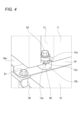
一方で、ジャンクションボックス11は、バッテリモジュール10及びバッテリケース31には固定されず、図4に示すように、アッパーフレーム34にマウントラバー80を介して固定される。より具体的に説明すると、アッパーフレーム34には、図3に示すように、前後方向において、アッパーフレーム34の前端部34aに位置する左右のボルト穴H1と、中央部34bに位置する左右のボルト穴H2との間に、4か所のボルト穴H5が設けられている。ジャンクションボックス11には、アッパーフレーム34のボルト穴H5と対応する位置に、前端部に2か所、後端部に2か所の合計4か所に切欠部13が設けられている。
On the other hand, the
切欠部13には、マウントラバー80が配置されている。マウントラバー80は、弾性材から構成され、全体として円筒形状を有する。より具体的には、マウントラバー80は、上大径部15aと下大径部15bとの間に小径部15cが設けられており、切欠部13に形成された板状の係止片13aに係合する。ジャンクションボックス11は、このマウントラバー80を貫通するボルトB3がアッパーフレーム34のボルト穴H5又はナットに螺合することにより、アッパーフレーム34に固定される。
A
即ち、バッテリモジュール10及びアッパーフレーム34がバッテリケース31に剛締結されているのに対し、ジャンクションボックス11はアッパーフレーム34にマウントラバー80を介して弾性結合で固定されている。
In other words, the
したがって、ジャンクションボックス11はバッテリとは異なる振動をとりやすくなる。即ち、ジャンクションボックス11の配置、ジャンクションボックス11の重さ、マウントラバー80の弾性、アッパーフレーム34の剛性などを調整することで、バッテリの位相とジャンクションボックス11の位相をずらしてバッテリパック1の振動を抑えることができる。
As a result, the
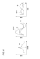
図6を参照して説明すると、ジャンクションボックス11をバッテリモジュール10及びアッパーフレーム34に剛締結すると、特定の周波数fで、バッテリの位相ABとジャンクションボックス11の位相AJが同位相となりバッテリモジュール10の振幅APが増幅してしまう。また、バッテリの位相ABとジャンクションボックス11の位相AJとをずらすことが難しい。これに対し、上記したようにジャンクションボックス11をアッパーフレーム34にマウントラバー80を介して弾性結合で固定し、ジャンクションボックス11の配置等を調整することで、バッテリの位相ABに対しジャンクションボックス11の位相AJを容易にずらすことができる。
Referring to FIG. 6, if the
バッテリの位相ABに対するジャンクションボックス11の位相AJのずらし方は、車両に搭載された際に想定される車両走行時の周波数帯域において、所定値を超えるような振動が発生しないように、振幅の最大値となる周波数が異なるように設定する。最も好ましくは、図6の右図に示すように、バッテリの位相ABとジャンクションボックス11の位相AJが逆位相となるように設定する。
The phase AJ of the
このように、本開示によれば、車両の走行時に想定される特定の周波数におけるバッテリパック1の振幅を抑えることができる。したがって、車両に搭載された際に想定される車両走行時の周波数帯域において、所定値を超えるような振動の発生を抑制できる。また、振動抑制のために特別な部材が必要ないため、重量増加を回避することができる。さらに、振動モードが安定化することによって更なる大型バッテリの搭載が可能となり、航続距離を延ばすことができる。 In this way, according to the present disclosure, it is possible to suppress the amplitude of the battery pack 1 at a specific frequency expected when the vehicle is running. Therefore, it is possible to suppress the occurrence of vibrations that exceed a predetermined value in the frequency band expected when the vehicle is running when installed in the vehicle. In addition, since no special components are required for vibration suppression, an increase in weight can be avoided. Furthermore, stabilizing the vibration mode makes it possible to install a larger battery, thereby extending the driving range.
また、特定の周波数fにおいて逆位相となるように設定すると、ジャンクションボックス11が振動したとき、バッテリモジュール10はジャンクションボックス11に反対方向に引っ張られる。ここで、ジャンクションボックス11が固定されるアッパーフレーム34は、電気端子が取り付けられていないバッテリモジュール10のカバープレート60に固定されている。したがって、逆位相による応力から電気端子を保護する追加的な保護構造を設ける必要がない。
Also, if the phase is set to be opposite at a specific frequency f, the
補器12は、アッパーフレーム34上にジャンクションボックス11の後方に配置されている。補器12は、図示は省略するが、アッパーフレーム34の中央部34bに位置する左右のボルト穴H2とアッパーフレーム34の後端部34cに位置する左右のボルト穴H3との間に剛締結されている。
The
上記実施形態では、マウントラバー80を用いて固定される個所がボルト穴H1とボルト穴H2との間のジャンクションボックス11の周辺に集約される。このようにマウントラバー80の固定部を集約することで、マウントラバー80の固定部をバッテリモジュール10等にも分散させる場合に比べて振動モードの調整が容易となる。
In the above embodiment, the locations where the mounting
続いて、上記実施形態の変形例について図5を参照しながら説明する。
以下で説明する変形例では、上記実施形態との相違点についてのみ説明する。上記実施形態では、アッパーフレーム34の中央部34bは、左右に位置する2つのボルト穴H2を通るボルトB1によって中央クロスメンバ334にのみ固定されていたが、本変形例では、バッテリモジュール10及び中央クロスメンバ334に固定される。
Next, a modification of the above embodiment will be described with reference to FIG.
In the following modified example, only the differences from the above embodiment will be described. In the above embodiment, the
即ち、本変形例のアッパーフレーム34の中央部34bには、前後左右に4つのボルト穴H2が設けられる。右前側のボルト穴H2は、右前のバッテリモジュール10の後方に位置するカバープレート60の左方の貫通穴61を通るボルトB1によって、バッテリケース31の中央クロスメンバ334の下部に設けられたモジュール固定部N1に右前のバッテリモジュール10と共締めされる。左前側のボルト穴H2は、左前のバッテリモジュール10の後方に位置するカバープレート60の右方の貫通穴61を通るボルトB1によって、バッテリケース31の中央クロスメンバ334の下部に設けられたモジュール固定部N1に左前のバッテリモジュール10と共締めされる。
In other words, four bolt holes H2 are provided on the front, rear, left and right sides in the
右後側のボルト穴H2は、右後のバッテリモジュール10の前方に位置するカバープレート60の左方の貫通穴61を通るボルトB1によって、バッテリケース31の中央クロスメンバ334の下部に設けられたモジュール固定部N1に右後のバッテリモジュール10と共締めされる。左後側のボルト穴H2は、左後のバッテリモジュール10の前方に位置するカバープレート60の右方の貫通穴61を通るボルトB1によって、バッテリケース31の中央クロスメンバ334の下部に設けられたモジュール固定部N1に左後のバッテリモジュール10と共締めされる。
The right rear bolt hole H2 is fastened together with the right
本変形例では、アッパーフレーム34の前端部34a及び後端部34cに加えて、中央部34bも、バッテリモジュール10とともにバッテリケース31にバッテリモジュール10と共締めされる。そして、各バッテリモジュール10は、前後方向に位置するカバープレート60の両方がアッパーフレーム34に固定される。したがって、アッパーフレーム34が振動するとき、アッパーフレーム34が全てのバッテリモジュール10の両端を引っ張るので、引張荷重がバッテリモジュール10の前後方向で一方側にのみ作用することが防止される。
In this modified example, in addition to the
以上、図面を参照しながら各種の実施の形態について説明したが、本発明はかかる例に限定されないことは言うまでもない。当業者であれば、特許請求の範囲に記載された範疇内において、各種の変更例又は修正例に想到し得ることは明らかであり、それらについても当然に本発明の技術的範囲に属するものと了解される。また、発明の趣旨を逸脱しない範囲において、上記実施の形態における各構成要素を任意に組み合わせてもよい。 Although various embodiments have been described above with reference to the drawings, it goes without saying that the present invention is not limited to such examples. It is clear that a person skilled in the art can come up with various modified or revised examples within the scope of the claims, and it is understood that these also naturally fall within the technical scope of the present invention. Furthermore, the components in the above embodiments may be combined in any manner as long as it does not deviate from the spirit of the invention.
上記実施形態では、アッパーフレーム34の固定部である、アッパーフレーム34の前端部34aに位置する左右のボルト穴H1とアッパーフレーム34の中央部34bに位置する左右のボルト穴H2との間に、ジャンクションボックス11を配置し、アッパーフレーム34の中央部34bに位置する左右のボルト穴H2とアッパーフレーム34の後端部34cに位置する左右のボルト穴H3との間に補器12を配置したが、これに限らない。
In the above embodiment, the
例えば、アッパーフレーム34の中央部34bに位置する左右のボルト穴H2とアッパーフレーム34の後端部34cに位置する左右のボルト穴H3との間にジャンクションボックス11を配置してもよい。また、アッパーフレーム34の固定部である、アッパーフレーム34の前端部34aに位置する左右のボルト穴H1とアッパーフレーム34の中央部34bに位置する左右のボルト穴H2との間に補器12を配置してもよい。
For example, the
また、マウントラバー80は、弾性的に結合している限り、全てが弾性部材で形成されている場合に限らず、一部に他の部材、例えば金属、樹脂等を含むものでもよい。
In addition, as long as the mounting
本明細書には少なくとも以下の事項が記載されている。なお、括弧内には、上記した実施形態において対応する構成要素等を示しているが、これに限定されるものではない。 This specification describes at least the following items. Note that the corresponding components in the above-mentioned embodiment are shown in parentheses, but are not limited to these.
(1) 複数のセルが積層されたバッテリモジュール(バッテリモジュール10)と、
前記バッテリモジュールをモジュール固定部(モジュール固定部N1)で固定するバッテリケース(バッテリケース31)と、
車両の前後方向に延設され、前記バッテリモジュールの上方に架設されるフレーム部材(アッパーフレーム34)と、
前記フレーム部材上に配置されるジャンクションボックス(ジャンクションボックス11)と、を備え、前記車両に搭載されるバッテリパック(バッテリパック1)であって、
前記フレーム部材は、前記ジャンクションボックスの前方に位置する第1固定部(ボルト穴H1)と、前記ジャンクションボックスの後方に位置する第2固定部(ボルト穴H2、ボルト穴H3)とで、前記バッテリケース又は前記バッテリモジュールに固定され、
前記ジャンクションボックスは、前記第1固定部と前記第2固定部との間に位置する中間固定部(ボルト穴H5)で、前記バッテリモジュール及び前記バッテリケースには固定されず、前記フレーム部材に固定され、
前記モジュール固定部、前記第1固定部、及び前記第2固定部は、弾性部材を介さない剛結合で固定され、
前記中間固定部は、弾性部材(マウントラバー80)を介して弾性結合で固定されている、バッテリパック。
(1) a battery module (battery module 10) in which a plurality of cells are stacked;
a battery case (battery case 31) that fixes the battery module at a module fixing portion (module fixing portion N1);
A frame member (upper frame 34) extending in the front-rear direction of the vehicle and installed above the battery module;
a junction box (junction box 11) disposed on the frame member; and a battery pack (battery pack 1) mounted on the vehicle,
The frame member is fixed to the battery case or the battery module by a first fixing portion (bolt hole H1) located in front of the junction box and a second fixing portion (bolt hole H2, bolt hole H3) located in the rear of the junction box,
the junction box is fixed to the frame member but not to the battery module or the battery case at an intermediate fixing portion (bolt hole H5) located between the first fixing portion and the second fixing portion,
the module fixing portion, the first fixing portion, and the second fixing portion are rigidly fixed to each other without using an elastic member;
The intermediate fixing portion is fixed by elastic coupling via an elastic member (mount rubber 80), in the battery pack.
(1)によれば、ジャンクションボックスがバッテリモジュールやバッテリケースに固定されていないので、ジャンクションボックスはバッテリとは異なる振動をとりやすくなる。即ち、バッテリパックの振幅が大きくなる固有振動数(周波数)に対して、ジャンクションボックスの配置と重さと中間固定部の弾性、フレーム部材の剛性等を調節することで、バッテリの位相とジャンクションボックスの位相をずらしてバッテリパックの振動を抑えることができる。また、剛結合の固定と弾性結合の固定を組み合わせ、中間固定部に弾性結合の場所を集中させているので、弾性結合を用いない場合や弾性結合の固定部をバッテリモジュール等にも分散させる場合に比べて振動モードの調整が容易となる。また、振動抑制のための重量増加を回避することができる。さらに、振動モードが安定化することによって更なる大型バッテリの搭載が可能となり、航続距離を延ばすことができる。 According to (1), since the junction box is not fixed to the battery module or the battery case, the junction box is likely to vibrate differently from the battery. That is, by adjusting the arrangement and weight of the junction box, the elasticity of the intermediate fixing part, the rigidity of the frame member, etc., for the natural frequency (frequency) at which the amplitude of the battery pack increases, the phase of the battery and the phase of the junction box can be shifted to suppress the vibration of the battery pack. In addition, since the rigid fixing and the elastic fixing are combined and the elastic fixing is concentrated in the intermediate fixing part, it is easier to adjust the vibration mode compared to when no elastic fixing is used or when the fixing part of the elastic fixing is distributed to the battery module, etc. Also, it is possible to avoid an increase in weight due to vibration suppression. Furthermore, by stabilizing the vibration mode, it is possible to mount a larger battery, and the driving range can be extended.
(2) (1)に記載のバッテリパックであって、
前記バッテリモジュールは、
セル積層体(セル積層体20)と、
前記セル積層体の積層方向両端で前記前後方向に延びるエンドプレート(エンドプレート37)と、
車幅方向に延びて、セル端子を覆うとともに電気端子が取り付けられていないカバープレート(カバープレート60)と、を有し、
前記フレーム部材は、前記第1固定部と前記第2固定部で前記カバープレートに固定されている、バッテリパック。
(2) The battery pack according to (1),
The battery module includes:
A cell stack (cell stack 20);
End plates (end plates 37) extending in the front-rear direction at both ends in the stacking direction of the cell stack;
a cover plate (cover plate 60) extending in the vehicle width direction, covering the cell terminals, and having no electrical terminals attached thereto;
The frame member is fixed to the cover plate at the first fixing portion and the second fixing portion.
(2)によれば、ジャンクションボックスを固定しているフレーム部材が、バッテリモジュールを直接引っ張ることができる。望ましくない振幅に至る固有振動数においてジャンクションボックスの振動とバッテリモジュールの振動が逆位相になるように調節することができるが、このとき、フレーム部材が電気端子が取り付けられていないカバープレートを引っ張るので、逆位相による応力から端子を保護する追加的な保護構造を設ける必要がない。 According to (2), the frame member that fixes the junction box can directly pull the battery module. The vibration of the junction box and the vibration of the battery module can be adjusted to be in opposite phase at a natural frequency that leads to an undesirable amplitude. In this case, since the frame member pulls the cover plate to which the electrical terminals are not attached, there is no need to provide an additional protective structure to protect the terminals from stress due to the opposite phase.
(3) (2)に記載のバッテリパックであって、
前記フレーム部材は、さらに、前記第2固定部を挟んで前記第1固定部とは反対側に位置する第3固定部(ボルト穴H3)で、前記バッテリモジュールに前記剛結合で固定され、
前記フレーム部材は、前記第1固定部、前記第2固定部、及び前記第3固定部により、前記バッテリケース内の全ての前記バッテリモジュールの両端に固定されている、バッテリパック。
(3) The battery pack according to (2),
The frame member is further rigidly fixed to the battery module at a third fixing portion (bolt hole H3) located on the opposite side of the second fixing portion from the first fixing portion,
The frame member is fixed to both ends of all of the battery modules in the battery case by the first fixing portion, the second fixing portion, and the third fixing portion.
(3)によれば、ジャンクションボックスを固定しているフレーム部材で、全てのバッテリモジュールの両端を直接引っ張るので、引張荷重がバッテリモジュールの前後方向で一方側にのみ作用することが防止され、バッテリケース内の全てのバッテリモジュールの両端に引張荷重が作用する。 According to (3), the frame member that secures the junction box directly pulls both ends of all battery modules, preventing the tensile load from acting on only one side in the front-to-rear direction of the battery module, and the tensile load acts on both ends of all battery modules in the battery case.
(4) (1)に記載のバッテリパックであって、
前記中間固定部の弾性部材はラバーで形成されている、バッテリパック。
(4) The battery pack according to (1),
The elastic member of the intermediate fixing portion is formed of rubber.
(4)によれば、構造設計を変更せずにラバーの材質を変更することで、中間固定部の弾性力が変わり、ジャンクションボックスが揺れる周波数を変化させることができる。これにより、弾性部材としてコイルばね、板ばね、皿バネなど金属製の弾性体を用いる場合に比べて、望ましくない振幅に至る固有振動数における振動モードの調整が容易となる。 According to (4), by changing the rubber material without changing the structural design, the elastic force of the intermediate fixing part changes, and the frequency at which the junction box vibrates can be changed. This makes it easier to adjust the vibration mode at the natural frequency that leads to an undesirable amplitude, compared to when a metallic elastic body such as a coil spring, leaf spring, or disc spring is used as the elastic member.
(5) (1)に記載のバッテリパックであって、
前記フレーム部材には、前記第1固定部の前方、又は、前記第2固定部の後方に補器が設けられ、
前記補器、前記ジャンクションボックス、及び前記バッテリモジュールの重量は、この順に大きい、バッテリパック。
(5) The battery pack according to (1),
An auxiliary device is provided in front of the first fixing portion or behind the second fixing portion of the frame member,
The weights of the auxiliary device, the junction box, and the battery module are largest in this order.
(5)によれば、ある程度重さのあるジャンクションボックスが揺れて逆位相を起こすことで、バッテリパックの振動を抑制しやすくなる。 According to (5), when the junction box, which has a certain amount of weight, vibrates and causes an opposite phase, it becomes easier to suppress the vibration of the battery pack.
1 バッテリパック
10 バッテリモジュール
11 ジャンクションボックス
20 セル積層体
31 バッテリケース
34 アッパーフレーム(フレーム部材)
37 エンドプレート
60 カバープレート
80 マウントラバー(弾性部材)
H1 ボルト穴(第1固定部)
H2 ボルト穴(第2固定部)
H3 ボルト穴(第3固定部)
H5 ボルト穴(中間固定部)
N1 モジュール固定部
REFERENCE SIGNS LIST 1
37
H1 Bolt hole (first fixing part)
H2 Bolt hole (second fixing part)
H3 Bolt hole (third fixing part)
H5 Bolt hole (middle fixing part)
N1 Module fixing part
Claims (5)
前記バッテリモジュールをモジュール固定部で固定するバッテリケースと、
車両の前後方向に延設され、前記バッテリモジュールの上方に架設されるフレーム部材と、
前記フレーム部材上に配置されるジャンクションボックスと、を備え、前記車両に搭載されるバッテリパックであって、
前記フレーム部材は、前記ジャンクションボックスの前方に位置する第1固定部と、前記ジャンクションボックスの後方に位置する第2固定部とで、前記バッテリケース又は前記バッテリモジュールに固定され、
前記ジャンクションボックスは、前記第1固定部と前記第2固定部との間に位置する中間固定部で、前記バッテリモジュール及び前記バッテリケースには固定されず、前記フレーム部材に固定され、
前記モジュール固定部、前記第1固定部、及び前記第2固定部は、弾性部材を介さない剛結合で固定され、
前記中間固定部は、弾性部材を介して弾性結合で固定されている、バッテリパック。 A battery module in which a plurality of cells are stacked;
a battery case that fixes the battery module at a module fixing portion;
A frame member extending in the front-rear direction of the vehicle and installed above the battery module;
a junction box disposed on the frame member,
the frame member is fixed to the battery case or the battery module by a first fixing portion located in front of the junction box and a second fixing portion located in the rear of the junction box,
the junction box is an intermediate fixing portion located between the first fixing portion and the second fixing portion, and is not fixed to the battery module or the battery case but is fixed to the frame member;
the module fixing portion, the first fixing portion, and the second fixing portion are rigidly fixed to each other without using an elastic member;
The intermediate fixing portion is fixed by elastic coupling via an elastic member.
前記バッテリモジュールは、
セル積層体と、
前記セル積層体の積層方向両端で前記前後方向に延びるエンドプレートと、
車幅方向に延びて、セル端子を覆うとともに電気端子が取り付けられていないカバープレートと、を有し、
前記フレーム部材は、前記第1固定部と前記第2固定部で前記カバープレートに固定されている、バッテリパック。 2. The battery pack according to claim 1,
The battery module includes:
A cell stack;
end plates extending in the front-rear direction at both ends in the stacking direction of the cell stack;
a cover plate extending in the vehicle width direction to cover the cell terminals and having no electrical terminals attached thereto;
The frame member is fixed to the cover plate at the first fixing portion and the second fixing portion.
前記フレーム部材は、さらに、前記第2固定部を挟んで前記第1固定部とは反対側に位置する第3固定部で、前記バッテリモジュールに前記剛結合で固定され、
前記フレーム部材は、前記第1固定部、前記第2固定部、及び前記第3固定部により、前記バッテリケース内の全ての前記バッテリモジュールの両端に固定されている、バッテリパック。 3. The battery pack according to claim 2,
The frame member is further rigidly fixed to the battery module at a third fixing portion located on an opposite side of the second fixing portion from the first fixing portion,
The frame member is fixed to both ends of all of the battery modules in the battery case by the first fixing portion, the second fixing portion, and the third fixing portion.
前記中間固定部の弾性部材はラバーで形成されている、バッテリパック。 2. The battery pack according to claim 1,
The elastic member of the intermediate fixing portion is formed of rubber.
前記フレーム部材には、前記第1固定部の前方、又は、前記第2固定部の後方に補器が設けられ、
前記補器、前記ジャンクションボックス、及び前記バッテリモジュールの重量は、この順に大きい、バッテリパック。 2. The battery pack according to claim 1,
An auxiliary device is provided in front of the first fixing portion or behind the second fixing portion of the frame member,
The weights of the auxiliary device, the junction box, and the battery module are largest in this order.
Priority Applications (3)
| Application Number | Priority Date | Filing Date | Title |
|---|---|---|---|
| JP2023048585A JP7641312B2 (en) | 2023-03-24 | 2023-03-24 | Battery pack |
| CN202410199441.2A CN118693430A (en) | 2023-03-24 | 2024-02-22 | Battery Pack |
| US18/588,032 US20240322339A1 (en) | 2023-03-24 | 2024-02-27 | Battery pack |
Applications Claiming Priority (1)
| Application Number | Priority Date | Filing Date | Title |
|---|---|---|---|
| JP2023048585A JP7641312B2 (en) | 2023-03-24 | 2023-03-24 | Battery pack |
Publications (2)
| Publication Number | Publication Date |
|---|---|
| JP2024137172A true JP2024137172A (en) | 2024-10-07 |
| JP7641312B2 JP7641312B2 (en) | 2025-03-06 |
Family
ID=92768804
Family Applications (1)
| Application Number | Title | Priority Date | Filing Date |
|---|---|---|---|
| JP2023048585A Active JP7641312B2 (en) | 2023-03-24 | 2023-03-24 | Battery pack |
Country Status (3)
| Country | Link |
|---|---|
| US (1) | US20240322339A1 (en) |
| JP (1) | JP7641312B2 (en) |
| CN (1) | CN118693430A (en) |
Citations (5)
| Publication number | Priority date | Publication date | Assignee | Title |
|---|---|---|---|---|
| JP2006160211A (en) * | 2004-12-10 | 2006-06-22 | Suzuki Motor Corp | Junction box mounting structure |
| JP2013218957A (en) * | 2012-04-11 | 2013-10-24 | Fuji Heavy Ind Ltd | Battery device for vehicle |
| JP2022077357A (en) * | 2020-11-11 | 2022-05-23 | 本田技研工業株式会社 | On-vehicle battery pack |
| JP2022143365A (en) * | 2021-03-17 | 2022-10-03 | 株式会社Subaru | Automotive battery protection structure |
| CN218228892U (en) * | 2022-08-25 | 2023-01-06 | 安徽华菱汽车有限公司 | Arrangement structure of pure electric vehicle transport vehicle |
-
2023
- 2023-03-24 JP JP2023048585A patent/JP7641312B2/en active Active
-
2024
- 2024-02-22 CN CN202410199441.2A patent/CN118693430A/en active Pending
- 2024-02-27 US US18/588,032 patent/US20240322339A1/en active Pending
Patent Citations (5)
| Publication number | Priority date | Publication date | Assignee | Title |
|---|---|---|---|---|
| JP2006160211A (en) * | 2004-12-10 | 2006-06-22 | Suzuki Motor Corp | Junction box mounting structure |
| JP2013218957A (en) * | 2012-04-11 | 2013-10-24 | Fuji Heavy Ind Ltd | Battery device for vehicle |
| JP2022077357A (en) * | 2020-11-11 | 2022-05-23 | 本田技研工業株式会社 | On-vehicle battery pack |
| JP2022143365A (en) * | 2021-03-17 | 2022-10-03 | 株式会社Subaru | Automotive battery protection structure |
| CN218228892U (en) * | 2022-08-25 | 2023-01-06 | 安徽华菱汽车有限公司 | Arrangement structure of pure electric vehicle transport vehicle |
Also Published As
| Publication number | Publication date |
|---|---|
| CN118693430A (en) | 2024-09-24 |
| JP7641312B2 (en) | 2025-03-06 |
| US20240322339A1 (en) | 2024-09-26 |
Similar Documents
| Publication | Publication Date | Title |
|---|---|---|
| JP6614012B2 (en) | Vehicle battery mounting structure | |
| CN111725450B (en) | Electricity storage device | |
| JP6770997B2 (en) | Battery module | |
| JP2013008524A (en) | Vehicle power supply device | |
| US20180194213A1 (en) | Battery pack | |
| JP2019117688A (en) | Battery pack | |
| JP2021030886A (en) | On-vehicle structure of electronic apparatus | |
| JP4754321B2 (en) | Fuel cell vehicle | |
| JP7641312B2 (en) | Battery pack | |
| US8361669B2 (en) | Fuel-cell-equipped apparatus with a fuel cell unit supported by three points | |
| US10056601B2 (en) | Battery pack | |
| KR20190101263A (en) | Enclosure of battery pack, battery pack and automobileusing the same | |
| US20240030540A1 (en) | Battery pack and electric apparatus | |
| US10618425B2 (en) | High voltage battery pack mounting systems for electrified vehicles | |
| US12142780B2 (en) | Equipment component fixation structure | |
| JP7838691B2 (en) | vehicle | |
| JP6493200B2 (en) | Battery pack for vehicle installation | |
| US20250023175A1 (en) | Power storage device | |
| JP7847068B2 (en) | Rechargeable battery pack | |
| US20260051594A1 (en) | Power storage device | |
| JP7740524B2 (en) | Electric vehicle drive unit | |
| JP7147588B2 (en) | power supply | |
| KR100792872B1 (en) | Body mounting structure of high voltage electric parts case | |
| JP2025127225A (en) | Power storage device and vehicle | |
| KR20250099986A (en) | Battery pack set and electric vehicle including the same |
Legal Events
| Date | Code | Title | Description |
|---|---|---|---|
| A621 | Written request for application examination |
Free format text: JAPANESE INTERMEDIATE CODE: A621 Effective date: 20231124 |
|
| TRDD | Decision of grant or rejection written | ||
| A01 | Written decision to grant a patent or to grant a registration (utility model) |
Free format text: JAPANESE INTERMEDIATE CODE: A01 Effective date: 20250128 |
|
| A61 | First payment of annual fees (during grant procedure) |
Free format text: JAPANESE INTERMEDIATE CODE: A61 Effective date: 20250221 |
|
| R150 | Certificate of patent or registration of utility model |
Ref document number: 7641312 Country of ref document: JP Free format text: JAPANESE INTERMEDIATE CODE: R150 |