JP2024134689A - Vane Pump - Google Patents
Vane Pump Download PDFInfo
- Publication number
- JP2024134689A JP2024134689A JP2023045017A JP2023045017A JP2024134689A JP 2024134689 A JP2024134689 A JP 2024134689A JP 2023045017 A JP2023045017 A JP 2023045017A JP 2023045017 A JP2023045017 A JP 2023045017A JP 2024134689 A JP2024134689 A JP 2024134689A
- Authority
- JP
- Japan
- Prior art keywords
- passage
- insertion hole
- vane pump
- housing
- rotor
- Prior art date
- Legal status (The legal status is an assumption and is not a legal conclusion. Google has not performed a legal analysis and makes no representation as to the accuracy of the status listed.)
- Pending
Links
Images


Classifications
-
- F—MECHANICAL ENGINEERING; LIGHTING; HEATING; WEAPONS; BLASTING
- F04—POSITIVE - DISPLACEMENT MACHINES FOR LIQUIDS; PUMPS FOR LIQUIDS OR ELASTIC FLUIDS
- F04C—ROTARY-PISTON, OR OSCILLATING-PISTON, POSITIVE-DISPLACEMENT MACHINES FOR LIQUIDS; ROTARY-PISTON, OR OSCILLATING-PISTON, POSITIVE-DISPLACEMENT PUMPS
- F04C2/00—Rotary-piston machines or pumps
- F04C2/30—Rotary-piston machines or pumps having the characteristics covered by two or more groups F04C2/02, F04C2/08, F04C2/22, F04C2/24 or having the characteristics covered by one of these groups together with some other type of movement between co-operating members
- F04C2/34—Rotary-piston machines or pumps having the characteristics covered by two or more groups F04C2/02, F04C2/08, F04C2/22, F04C2/24 or having the characteristics covered by one of these groups together with some other type of movement between co-operating members having the movement defined in groups F04C2/08 or F04C2/22 and relative reciprocation between the co-operating members
- F04C2/344—Rotary-piston machines or pumps having the characteristics covered by two or more groups F04C2/02, F04C2/08, F04C2/22, F04C2/24 or having the characteristics covered by one of these groups together with some other type of movement between co-operating members having the movement defined in groups F04C2/08 or F04C2/22 and relative reciprocation between the co-operating members with vanes reciprocating with respect to the inner member
- F04C2/3446—Rotary-piston machines or pumps having the characteristics covered by two or more groups F04C2/02, F04C2/08, F04C2/22, F04C2/24 or having the characteristics covered by one of these groups together with some other type of movement between co-operating members having the movement defined in groups F04C2/08 or F04C2/22 and relative reciprocation between the co-operating members with vanes reciprocating with respect to the inner member the inner and outer member being in contact along more than one line or surface
-
- F—MECHANICAL ENGINEERING; LIGHTING; HEATING; WEAPONS; BLASTING
- F04—POSITIVE - DISPLACEMENT MACHINES FOR LIQUIDS; PUMPS FOR LIQUIDS OR ELASTIC FLUIDS
- F04C—ROTARY-PISTON, OR OSCILLATING-PISTON, POSITIVE-DISPLACEMENT MACHINES FOR LIQUIDS; ROTARY-PISTON, OR OSCILLATING-PISTON, POSITIVE-DISPLACEMENT PUMPS
- F04C15/00—Component parts, details or accessories of machines, pumps or pumping installations, not provided for in groups F04C2/00 - F04C14/00
- F04C15/06—Arrangements for admission or discharge of the working fluid, e.g. constructional features of the inlet or outlet
-
- F—MECHANICAL ENGINEERING; LIGHTING; HEATING; WEAPONS; BLASTING
- F04—POSITIVE - DISPLACEMENT MACHINES FOR LIQUIDS; PUMPS FOR LIQUIDS OR ELASTIC FLUIDS
- F04C—ROTARY-PISTON, OR OSCILLATING-PISTON, POSITIVE-DISPLACEMENT MACHINES FOR LIQUIDS; ROTARY-PISTON, OR OSCILLATING-PISTON, POSITIVE-DISPLACEMENT PUMPS
- F04C2240/00—Components
- F04C2240/30—Casings or housings
Landscapes
- Engineering & Computer Science (AREA)
- Mechanical Engineering (AREA)
- General Engineering & Computer Science (AREA)
- Rotary Pumps (AREA)
- Details And Applications Of Rotary Liquid Pumps (AREA)
Abstract
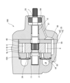
【課題】ベーンポンプの作動を安定させる。【解決手段】ベーンポンプ100は、ハウジング25を貫通しないようにハウジング25に形成されて駆動シャフト1が挿入される挿入孔15と、駆動シャフト1の外周面と挿入孔15の内周面との間に圧縮した状態で設けられるシール部材55と、ロータ2とカムリング4と一対の隣り合うベーン3とによって区画されるポンプ室6に作動流体を導くとともにハウジング25に形成される吸い込み通路50と、吸い込み通路50に連通しカムリング4の外周面とハウジング25の内周面との間に形成される環状通路18と、挿入孔15と環状通路18とを連通し挿入孔15内に漏出した作動流体を環状通路18に導くドレン通路57と、を備える。【選択図】図3[Problem] To stabilize the operation of a vane pump. [Solution] A vane pump 100 includes an insertion hole 15 formed in a housing 25 into which a drive shaft 1 is inserted so as not to penetrate the housing 25, a seal member 55 provided in a compressed state between the outer circumferential surface of the drive shaft 1 and the inner circumferential surface of the insertion hole 15, a suction passage 50 formed in the housing 25 and directing working fluid to a pump chamber 6 defined by a rotor 2, a cam ring 4, and a pair of adjacent vanes 3, an annular passage 18 communicating with the suction passage 50 and formed between the outer circumferential surface of the cam ring 4 and the inner circumferential surface of the housing 25, and a drain passage 57 communicating between the insertion hole 15 and the annular passage 18 and directing working fluid leaked into the insertion hole 15 to the annular passage 18. [Selected Figure] Figure 3
Description
本発明は、ベーンポンプに関するものである。 The present invention relates to a vane pump.
特許文献1には、駆動軸と、駆動軸に回転駆動されるポンプ要素と、ポンプ要素を収容するポンプハウジングと、駆動軸とポンプハウジングとの間をシールするシール部材と、を備えるポンプ装置が開示されている。シール部材は、駆動軸を収容する駆動軸収容穴に設けられて駆動軸とポンプハウジングとの間をシールし、ポンプ要素から作動液がポンプハウジング外に漏出することを防止する。また、駆動軸収容穴には、作動液をポンプ要素に供給する吸入通路と連通する戻し通路が設けられる。ポンプ要素から駆動軸収容穴に漏出した作動液は、シール部材によりポンプハウジング外に漏出することが防止されつつ、戻し通路により吸入通路に導かれて再度ポンプ要素に供給される。
特許文献1に記載のようなベーンポンプでは、例えば、ポンプ要素から吐出された作動液が吸込通路に還流されることにより、吸入通路内の圧力が高くなる場合がある。吸入通路内が高圧になると、戻し通路を通じてシール部材に高い圧力が作用してしまい、不具合が生じることで、ベーンポンプの作動が不安定になるおそれがある。
In a vane pump such as that described in
本発明は、上記の問題点に鑑みてなされたものであり、ベーンポンプの作動を安定させることを目的とする。 The present invention was made in consideration of the above problems, and aims to stabilize the operation of the vane pump.
本発明は、ベーンポンプであって、駆動シャフトに連結され回転駆動されるロータと、ロータに対して径方向に往復動自在に設けられる複数のベーンと、ロータの回転に伴ってベーンの先端部が摺接する内周カム面を有するカムリングと、カムリングが収容されるハウジングと、ハウジングを貫通しないようにハウジングに形成されて駆動シャフトが挿入される挿入孔と、駆動シャフトの外周面と挿入孔の内周面との間に圧縮した状態で設けられるシール部材と、ロータとカムリングと一対の隣り合うベーンとによって区画されるポンプ室に作動流体を導くとともにハウジングに形成される吸い込み通路と、吸い込み通路に連通しカムリングの外周面とハウジングの内周面との間に形成される環状通路と、挿入孔と環状通路とを連通し挿入孔内に漏出した作動流体を環状通路に導くドレン通路と、を備えることを特徴とする。 The present invention is a vane pump that includes a rotor that is connected to a drive shaft and driven to rotate, a plurality of vanes that are provided so as to be capable of reciprocating radially relative to the rotor, a cam ring having an inner cam surface against which the tips of the vanes slide as the rotor rotates, a housing that accommodates the cam ring, an insertion hole formed in the housing and into which the drive shaft is inserted so as not to penetrate the housing, a seal member that is provided in a compressed state between the outer circumferential surface of the drive shaft and the inner circumferential surface of the insertion hole, a suction passage formed in the housing that guides the working fluid to a pump chamber defined by the rotor, the cam ring, and a pair of adjacent vanes, an annular passage that communicates with the suction passage and is formed between the outer circumferential surface of the cam ring and the inner circumferential surface of the housing, and a drain passage that communicates with the insertion hole and the annular passage and guides the working fluid that has leaked into the insertion hole to the annular passage.
この発明では、ドレン通路が、カムリングの外周面とハウジングの内周面との間に形成される環状通路を通じて吸い込み通路と連通する。そのため、吸い込み通路内が高圧になっても、吸い込み通路内の圧力上昇に伴うドレン通路内の圧力上昇が抑制され、シール部材に高い圧力が作用することが防止されるため、ベーンポンプの作動が安定する。 In this invention, the drain passage communicates with the suction passage through an annular passage formed between the outer peripheral surface of the cam ring and the inner peripheral surface of the housing. Therefore, even if the suction passage becomes high pressure, the pressure rise in the drain passage associated with the pressure rise in the suction passage is suppressed, and high pressure is prevented from acting on the sealing member, stabilizing the operation of the vane pump.
また、本発明は、環状通路は、吸い込み通路よりも流路断面積が小さいことを特徴とする。 The present invention is also characterized in that the annular passage has a smaller flow cross-sectional area than the suction passage.
また、本発明は、ベーンポンプであって、環状通路とドレン通路とを連通し駆動シャフトの軸方向に延びて形成される軸方向通路をさらに備え、環状通路は、軸方向通路と吸い込み通路の間に設けられることを特徴とする。 The present invention also provides a vane pump that further includes an axial passage that connects the annular passage and the drain passage and extends in the axial direction of the drive shaft, and the annular passage is disposed between the axial passage and the suction passage.
また、本発明は、環状通路の流路断面積は、ドレン通路の流路断面積よりも小さいことを特徴とする。 The present invention is also characterized in that the flow cross-sectional area of the annular passage is smaller than the flow cross-sectional area of the drain passage.
これらの発明では、吸い込み通路内が高圧になっても、吸い込み通路内の圧力上昇に伴うドレン通路内の圧力上昇がさらに抑制され、シール部材に高い圧力が作用することが防止される。 With these inventions, even if the pressure inside the suction passage becomes high, the pressure increase inside the drain passage that accompanies the pressure increase inside the suction passage is further suppressed, preventing high pressure from acting on the sealing member.
また、本発明は、挿入孔には、駆動シャフトを回転自在に支持するブッシュが設けられ、ドレン通路は、挿入孔におけるシール部材とブッシュとの間に連通することを特徴とする。 The present invention is also characterized in that the insertion hole is provided with a bushing that rotatably supports the drive shaft, and the drain passage communicates between the seal member in the insertion hole and the bushing.
この発明では、挿入孔内に漏出した作動流体がブッシュと駆動シャフトの摺動面を潤滑してドレン通路に導かれるため、ベーンポンプの作動が安定する。 In this invention, the working fluid that leaks into the insertion hole lubricates the sliding surfaces of the bush and drive shaft and is guided to the drain passage, stabilizing the operation of the vane pump.
本発明によれば、ベーンポンプの作動が安定する。 According to the present invention, the operation of the vane pump is stable.
以下、図面を参照して、本発明の実施形態に係るベーンポンプ100について説明する。ベーンポンプ100は、車両に搭載される流体圧機器70(例えば、パワーステアリング装置や変速機等)の流体圧供給源として用いられる。ここでは、作動流体として作動油が用いられる固定容量型のベーンポンプ100について説明するが、作動水等の他の流体を作動流体として用いてもよく、ベーンポンプ100が可変容量型であってもよい。
Below, a
図1はベーンポンプ100の断面図であり、図2はポンプカバー20及びカバー側サイドプレート40を取り外した状態でのロータ2、ベーン3、カムリング4及びポンプボディ10の平面図である。なお、図1は、図2のI-I線に沿った断面である。
Figure 1 is a cross-sectional view of the
図1及び図2に示すように、ベーンポンプ100は、ハウジング25と、ハウジング25に回転自在に支持される駆動シャフト1と、ハウジング25に貫通しないように形成され駆動シャフト1が挿入される挿入孔15と、駆動シャフト1に連結されて回転駆動されるロータ2と、ロータ2の外周面に開口する複数のスリット2sと、ロータ2のスリット2sに摺動自在に挿入されロータ2に対して径方向に往復動自在に設けられる複数のベーン3と、ロータ2の回転に伴ってベーン3の先端部3a(図2参照)が摺接する内周カム面4aを有するカムリング4と、を備える。ハウジング25は、収容凹部10Aを有するポンプボディ10と、収容凹部10Aを覆いポンプボディ10に固定されるポンプカバー20(図1参照)と、を有する。カムリング4はロータ2及びベーン3を収容する。
1 and 2, the
ベーンポンプ100は、例えばエンジンや電動モータ等の駆動装置(図示せず)によって駆動される。図1に示すように、ハウジング25には、挿入孔15がポンプカバー20を貫通するとともにポンプボディ10を貫通しないように延びて形成される。ポンプボディ10には、挿入孔15よりも大径な収容凹部10Aが挿入孔15と連続して形成される。ベーンポンプ100では、ロータ2及びベーン3を収容したカムリング4がポンプボディ10の収容凹部10Aに収容され、駆動シャフト1が挿入孔15に挿入されて、ロータ2が駆動シャフト1に連結される。ベーンポンプ100は、ロータ2が図2の矢印で示すように反時計回りに回転駆動されることにより流体圧を発生させる。駆動シャフト1は、挿入孔15に設けられるブッシュ11,12を介して、ハウジング25に回転自在に支持される。
The
以下において、ロータ2の回転軸(言い換えれば、駆動シャフト1)に沿う方向を「軸方向」と称し、ロータ2の回転軸を中心とする放射方向を「径方向」と称し、ベーンポンプ100の作動時にロータ2が回転する方向を「周方向」と称する。
In the following, the direction along the rotation axis of the rotor 2 (in other words, the drive shaft 1) is referred to as the "axial direction", the radial direction centered on the rotation axis of the
図1に示すように、ベーンポンプ100は、ロータ2の軸方向一端側に設けられ、ロータ2及びカムリング4の一方の側面に接触して設けられるボディ側サイドプレート30と、ロータ2の軸方向他端側に設けられ、ロータ2及びカムリング4の他方の側面に接触して設けられるカバー側サイドプレート40と、をさらに備える。
As shown in FIG. 1, the
ボディ側サイドプレート30は、収容凹部10Aの底面とロータ2との間に設けられる。ボディ側サイドプレート30には、ロータ2の軸方向一端面(図1における下側の端面)が摺接するとともにカムリング4の軸方向一端面(図1における下側の端面)が当接する。カバー側サイドプレート40は、ロータ2とポンプカバー20との間に設けられる。カバー側サイドプレート40には、ロータ2の軸方向他端面(図1における上側の端面)が摺接するとともにカムリング4の軸方向他端面(図1における上側の端面)が当接する。
The body-
このようにして、ボディ側サイドプレート30とカバー側サイドプレート40は、ロータ2及びカムリング4の両側面に対向する状態で配置される。つまり、ボディ側サイドプレート30及びカバー側サイドプレート40は、ロータ2及びカムリング4を軸方向に挟んで配置される。
In this way, the
ボディ側サイドプレート30、ロータ2、カムリング4、及びカバー側サイドプレート40は、ポンプボディ10の収容凹部10Aに収容される。この状態で、ポンプボディ10にポンプカバー20が取付けられることで、収容凹部10Aは封止される。
The
図2に示すように、ロータ2には、複数のスリット2sが放射状に形成される。スリット2sは、ロータ2の外周に開口する。
As shown in FIG. 2,
ベーン3は、矩形平板状に形成される。ベーン3は、スリット2sに摺動自在に挿入され、スリット2sから突出する方向の端部である先端部3aと、先端部3aとは反対側の端部である基端部3bと、を有する。スリット2s内において、ベーン3の基端部3bによって背圧室5が画成される。背圧室5は後述するように高圧室14と連通し、背圧室5には高圧室14から作動油が導かれる。ベーン3は、背圧室5に導かれる作動油の圧力によりスリット2sから突出する方向に押圧される。
The
カムリング4は、略長円形状をした内周面である内周カム面4aを有する環状の部材である。内周カム面4aは、ロータ2の回転に伴って複数のベーン3の先端部3aが摺接する面である。
The
ロータ2が回転すると、ベーン3に遠心力が生じる。この遠心力によって、ベーン3はスリット2sから突出する方向に押圧される。つまり、ベーン3は、基端部3bを押圧する背圧室5の流体圧力と、ロータ2の回転に伴って働く遠心力と、によってスリット2sから突出する方向(径方向外方)に押圧される。ベーン3が径方向外方に押圧されると、ベーン3の先端部3aがカムリング4の内周カム面4aに摺接する。これにより、カムリング4の内部には、ロータ2の外周面、カムリング4の内周カム面4a、及び一対の隣り合うベーン3によって、ポンプ室6が区画される。
When the
内周カム面4aは、略楕円状に形成される。そのため、ロータ2の回転に伴い、ポンプ室6の容積は拡張と収縮とを繰り返す。ポンプ室6が拡張する拡張領域(吸込領域)では作動油が吸入され、ポンプ室6が収縮する収縮領域(吐出領域)では作動油が吐出される。
The
カムリング4は、ポンプボディ10の収容凹部10Aと略同じもしくは収容凹部10Aよりも小径に形成される。カムリング4は、位置決めピン8が挿通されるピン孔4bを有し、位置決めピン8がピン孔4b及びポンプカバー20のピン孔(図示省略)に挿通されることにより、ハウジング25に対して位置決めされる。このように、カムリング4の位置決めは、ポンプボディ10の収容凹部10Aに嵌め込まれることによって行われるものではない。そのため、ベーンポンプ100は、カムリング4の外周面とポンプボディ10の内周面との間に形成されるクリアランスとしての環状通路18を備える。本実施形態のベーンポンプ100では、環状通路18は、周方向の全周にわたって形成される。
The
図1に示すように、ポンプボディ10の収容凹部10Aの底面側には、ポンプボディ10とボディ側サイドプレート30によって環状の高圧室14が画成される。高圧室14は、収容凹部10Aの底面とボディ側サイドプレート30との間に設けられ、ポンプ室6から吐出される高圧の作動油が導かれる。高圧室14は、吐出通路62を介してベーンポンプ100の外部の流体圧機器70(例えば、パワーステアリング装置、変速機等)に接続される。
As shown in FIG. 1, an annular high-
ポンプカバー20には低圧室21が形成され、収容凹部10Aの内周面には低圧室21と連通する迂回通路13が形成される。迂回通路13は、図2にも示すように、カムリング4を挟んで対向する位置に二か所設けられる。低圧室21は、タンク通路61を介してタンク60に接続される。低圧室21と迂回通路13により、後述するようにポンプ室6に作動油を導く吸い込み通路50が形成される。吸い込み通路50は、周方向の一部の領域に形成され、環状通路18に連通する(図2参照)。
A
図1に示すように、吐出通路62には、流体圧機器70に供給される作動油の流量を制御する流量制御弁80が設けられる。流量制御弁80は、公知の構成を採用できるため、詳細な説明は省略する。流量制御弁80は、流体圧機器70に供給される作動油の一部を、還流通路81を通じてタンク通路61に還流させる。言い換えれば、流量制御弁80は、流体圧機器70に供給される作動油の一部を、ベーンポンプ100の吸い込み側に還流させる。
As shown in FIG. 1, the
図1、図2に示すように、ボディ側サイドプレート30は、吐出領域に対応するように形成される吐出ポート31(図2参照)と、駆動シャフト1が挿通する貫通孔(図示省略)と、吸込領域に対応するように形成される吸込ポート33と、ロータ2の周方向に互いに間隔を空けて設けられ背圧室5に連通する背圧溝34と、位置決めピン8が挿通するピン孔(図示省略)と、を有する。
As shown in Figures 1 and 2, the
吐出ポート31は、ボディ側サイドプレート30を貫通して形成され、ポンプ室6から吐出される作動油を高圧室14へと導く。吸込ポート33は、径方向外側に開口する凹形状となるように形成され、吸い込み通路50の迂回通路13からポンプ室6に作動油を導く。背圧溝34は、ロータ2の回転に伴い、複数の背圧室5と重なり連通する。背圧溝34は、ボディ側サイドプレート30を貫通して形成され、高圧室14と連通する。これにより、吐出ポート31からの高圧の作動油は、高圧室14及び背圧溝34を通じて背圧室5に導かれる。背圧室5は、背圧溝34を通じて導かれる作動油によりベーン3を内周カム面4aに向けて押圧し、ベーン3を内周カム面4aに摺接させる。
The
図1に示すように、カバー側サイドプレート40は、駆動シャフト1が挿通する貫通孔(図示省略)と、吸込領域に対応するように形成される吸込ポート43と、位置決めピン8が挿通するピン孔(図示省略)と、を有する。
As shown in FIG. 1, the
吸込ポート43は、カバー側サイドプレート40を貫通して形成され、吸い込み通路50の低圧室21からポンプ室6に作動油を導く。よって、ポンプ室6には、ボディ側サイドプレート30の吸込ポート33及びカバー側サイドプレート40の吸込ポート43を通じて作動油が導かれる。ボディ側サイドプレート30及びカバー側サイドプレート40は、カムリング4と同様に、位置決めピン8によってハウジング25に対して位置決めされる。
The
ここで、ベーンポンプ100では、作動油がロータ2とボディ側サイドプレート30の間やロータ2とカバー側サイドプレート40の間等を通じて、挿入孔15に漏出することがある。そのため、図3に示すように、ベーンポンプ100は、挿入孔15に漏出した作動油がハウジング25外に漏出することを防止するシール部材55を備える。シール部材55は、駆動シャフト1の外周面と挿入孔15の内周面との間に圧縮した状態で設けられる。具体的には、挿入孔15は小径部と大径部を有し、大径部によりシール部材収容空間56が形成される。シール部材収容空間56は、挿入孔15の一部であり、ポンプカバー20に形成される。シール部材55は、シール部材収容空間56に設けられて、作動油がハウジング25外に漏出することを防止する。
Here, in the
図3に示すように、ベーンポンプ100は、ポンプカバー20に形成され挿入孔15内に漏出した作動油を環状通路18に導くドレン通路57と、ドレン通路57に連通し径方向に延びてポンプカバー20に形成される径方向通路58と、環状通路18とドレン通路57とを連通し軸方向に延びてポンプボディ10に形成される軸方向通路59と、を備える。
As shown in FIG. 3, the
ドレン通路57は、シール部材収容空間56から径方向通路58にわたって直線状に延びて形成される。ドレン通路57は、挿入孔15(シール部材収容空間56)におけるシール部材55とブッシュ12との間に連通する。径方向通路58は、ポンプカバー20の端面に開口して形成され、ドレン通路57と軸方向通路59を連通する。軸方向通路59は、ポンプボディ10の端面に開口して形成され、径方向通路58と環状通路18を連通する。軸方向通路59は、収容凹部10Aの内周面に形成され、カムリング4、ボディ側サイドプレート30、及びカバー側サイドプレート40の外周面に臨むように形成される。径方向通路58及び軸方向通路59の流路断面積は、ドレン通路57の流路断面積よりも大きい。径方向通路58及び軸方向通路59は、環状通路18とドレン通路57を接続する機能を有する。
The
本実施形態では、ドレン通路57、径方向通路58、及び軸方向通路59は、吸い込み通路50から周方向に離れて一つずつ形成される(図2参照)。そのため、軸方向通路59は、吸い込み通路50に直接連通せずに、環状通路18を介して吸い込み通路50に連通する。よって、挿入孔15に漏出した作動油は、ドレン通路57、径方向通路58、軸方向通路59、及び環状通路18を通じて、吸い込み通路50に導かれ還流される。言い換えれば、ドレン通路57、径方向通路58、軸方向通路59、及び環状通路18は、挿入孔15と吸い込み通路50を連通するための接続通路として機能する。このようにして、ドレン通路57は挿入孔15と環状通路18とを連通する。
In this embodiment, the
挿入孔15に漏出した作動油が吸い込み通路50に還流されることで、挿入孔15内に作動油が溜まってしまうことが防止される。よって、挿入孔15内の作動油の圧力により駆動シャフト1が押し上げられてロータ2が焼き付いてしまうということが防止される。なお、ドレン通路57、径方向通路58、及び軸方向通路59が形成される位置は、図2で示す位置に限らず、軸方向通路59が吸い込み通路50に直接連通しなければよい。
The hydraulic oil leaking into the
ここで、本実施形態のベーンポンプ100では、上記のように、流体圧機器70に供給される作動油の一部を流量制御弁80がタンク通路61に還流させる。そのため、流量制御弁80からタンク通路61に還流する作動油の流量が多くなると、吸い込み通路50内の圧力が高くなる場合がある。仮にベーンポンプ100が環状通路18を備えず、ドレン通路57が吸い込み通路50に直接連通する構成である場合には、吸い込み通路50内が流量制御弁80から還流する作動油により高圧になり、ドレン通路57を通じてシール部材55に高い圧力が作用する。これにより、シール部材55の損傷や外れ等の不具合が生じることで、ベーンポンプ100の作動が不安定になるおそれがある。
In the
しかしながら、本実施形態のベーンポンプ100では、ドレン通路57が、カムリング4の外周面とハウジング25の内周面との間に形成される環状通路18を通じて吸い込み通路50と連通する。環状通路18は、カムリング4の外周面とハウジング25の内周面との間に形成されるクリアランスであるため、流路断面積が小さい。より具体的には、環状通路18は、吸い込み通路50よりも流路断面積が小さい。そのため、吸い込み通路50内が高圧になっても、環状通路18で大きな圧力損失が生じることにより、吸い込み通路50内の圧力上昇に伴うドレン通路57内の圧力上昇が抑制される。これにより、シール部材55に高い圧力が作用することが防止されるため、ベーンポンプ100の作動が安定する。
However, in the
また、ベーンポンプ100では、環状通路18が軸方向通路59と吸い込み通路50の間に設けられ、環状通路18の流路断面積は、ドレン通路57の流路断面積よりも小さい。これにより、環状通路18で生じる圧力損失が大きくなり、吸い込み通路50内の圧力上昇に伴うドレン通路57内の圧力上昇がさらに抑制される。なお、吸い込み通路50内の圧力上昇に伴うドレン通路57内の圧力上昇が抑制できれば、環状通路18の流路断面積がドレン通路57の流路断面積より大きくてもよい。
In addition, in the
また、ベーンポンプ100では、ドレン通路57は、挿入孔15におけるシール部材55とブッシュ12との間に連通する。よって、挿入孔15内に漏出した作動油がブッシュ12と駆動シャフト1の摺動面を潤滑してドレン通路57に導かれるため、ベーンポンプ100の作動が安定する。
In addition, in the
次に、ベーンポンプ100の動作について説明する。
Next, the operation of the
エンジン等の駆動装置(図示せず)の動力によって駆動シャフト1が回転駆動されると、ロータ2が図2に矢印で示す方向に回転する。ロータ2の回転に伴って、吸込領域に位置するポンプ室6が拡張する。これにより、タンク60内の作動油が、図1に示すように、タンク通路61、吸い込み通路50、ボディ側サイドプレート30の吸込ポート33及びカバー側サイドプレート40の吸込ポート43を通じてポンプ室6に吸い込まれる。また、ロータ2の回転に伴って、吐出領域に位置するポンプ室6が収縮する。これにより、ポンプ室6内の作動油が、吐出ポート31(図2参照)を通じて高圧室14に吐出される。高圧室14に吐出された作動油は、吐出通路62を通じて外部の流体圧機器70へと供給される。本実施形態のベーンポンプ100では、ロータ2が一回転する間に、各ポンプ室6が作動油の吸込、吐出を二回繰り返す。
When the
高圧室14に吐出された作動油の一部は、背圧溝34を通じて背圧室5に供給され、ベーン3の基端部3bを内周カム面4aに向かって押圧する。したがって、ベーン3は、基端部3bを押圧する背圧室5の流体圧力と、ロータ2の回転に伴って働く遠心力と、によってスリット2sから突出する方向に押圧される。これにより、ベーン3の先端部3aがカムリング4の内周カム面4aに摺接しながら回転するので、ポンプ室6内の作動油は、ベーン3の先端部3aとカムリング4の内周カム面4aとの間から漏れることなく吐出ポート31から吐出される。
A portion of the hydraulic oil discharged into the
以上の本実施形態によれば、以下に示す効果を奏する。 This embodiment provides the following advantages:
ベーンポンプ100では、ドレン通路57が、カムリング4の外周面とハウジング25の内周面との間に形成される環状通路18を通じて吸い込み通路50と連通する。そのため、吸い込み通路50内が高圧になっても、吸い込み通路50内の圧力上昇に伴うドレン通路57内の圧力上昇が抑制され、シール部材55に高い圧力が作用することが防止されるため、ベーンポンプ100の作動が安定する。
In the
次に、本実施形態の変形例について説明する。以下のような変形例も本発明の範囲内であり、変形例に示す構成と上述の実施形態で説明した構成を組み合わせたり、以下の異なる変形例で説明する構成同士を組み合わせたりすることも可能である。 Next, modified examples of this embodiment will be described. The following modified examples are also within the scope of the present invention, and it is possible to combine the configuration shown in the modified example with the configuration described in the above embodiment, or to combine the configurations described in the different modified examples below.
<変形例1>
上記実施形態では、ベーンポンプ100は、ボディ側サイドプレート30と、カバー側サイドプレート40と、を備える。しかしながら、ボディ側サイドプレート30及びカバー側サイドプレート40は、ベーンポンプ100に必須の構成ではない。この構成であっても、上記実施形態と同様の効果を奏する。
<
In the above embodiment, the
<変形例2>
上記実施形態では、吐出通路62には流体圧機器70に供給される作動油の流量を制御する流量制御弁80が設けられ、流量制御弁80は流体圧機器70に供給される作動油の一部をタンク通路61に還流させる。しかしながら、吐出通路62には流量制御弁80が設けられなくてもよい。流量制御弁80が設けられない場合であっても、例えば、流体圧機器70が作動油の流量を制御する構成を有し、作動油の一部をタンク通路61に還流させる場合には、吸い込み通路50内の圧力が高くなる可能性がある。ベーンポンプ100では、このような要因により吸い込み通路50内が高圧になっても、吸い込み通路50内の圧力上昇に伴うドレン通路57内の圧力上昇が抑制され、シール部材55に高い圧力が作用することが防止されるため、ベーンポンプ100の作動が安定する。
<
In the above embodiment, the
<変形例3>
上記実施形態では、ベーンポンプ100は、ドレン通路57に連通する径方向通路58と、径方向通路58及び環状通路18に連通する軸方向通路59と、を備える。しかしながら、ドレン通路57と環状通路18を連通する通路の構成は上記に限らない。例えば、ベーンポンプ100が径方向通路58及び軸方向通路59を備えず、ドレン通路57が挿入孔15と環状通路18とを直接連通する構成であってもよい。
<
In the above embodiment, the
さらに、上記実施形態では、ドレン通路57、径方向通路58、及び軸方向通路59は、吸い込み通路50から周方向に離れて一つずつ形成される。これに限らず、ドレン通路57、径方向通路58、及び軸方向通路59は、環状通路18を介して吸い込み通路50に連通する構成であれば、複数形成されてもよい。
Furthermore, in the above embodiment, the
<変形例4>
上記実施形態では、カムリング4の外周面とポンプボディ10の内周面との間に形成されるクリアランスとしての環状通路18が、周方向の全周にわたって形成される。これに限らず、環状通路18は、吸い込み通路50に連通する構成であれば、周方向の一部の領域にのみ形成されてもよい。
<
In the above embodiment, the
以下、本発明の実施形態の構成、作用、及び効果をまとめて説明する。 The configuration, operation, and effects of the embodiment of the present invention are summarized below.
ベーンポンプ100は、駆動シャフト1に連結され回転駆動されるロータ2と、ロータ2に対して径方向に往復動自在に設けられる複数のベーン3と、ロータ2の回転に伴ってベーン3の先端部3aが摺接する内周カム面4aを有するカムリング4と、カムリング4が収容されるハウジング25と、ハウジング25を貫通しないようにハウジング25に形成されて駆動シャフト1が挿入される挿入孔15と、駆動シャフト1の外周面と挿入孔15の内周面との間に圧縮した状態で設けられるシール部材55と、ロータ2とカムリング4と一対の隣り合うベーン3とによって区画されるポンプ室6に作動流体を導くとともにハウジング25に形成される吸い込み通路50と、吸い込み通路50に連通しカムリング4の外周面とハウジング25の内周面との間に形成される環状通路18と、挿入孔15と環状通路18とを連通し挿入孔15内に漏出した作動流体を環状通路18に導くドレン通路57と、を備える。
The
この構成では、ドレン通路57が、カムリング4の外周面とハウジング25の内周面との間に形成される環状通路18を通じて吸い込み通路50と連通する。そのため、吸い込み通路50内が高圧になっても、吸い込み通路50内の圧力上昇に伴うドレン通路57内の圧力上昇が抑制され、シール部材55に高い圧力が作用することが防止されるため、ベーンポンプ100の作動が安定する。
In this configuration, the
また、ベーンポンプ100では、環状通路18は、吸い込み通路50よりも流路断面積が小さい。
In addition, in the
また、ベーンポンプ100は、環状通路18とドレン通路57とを連通し駆動シャフト1の軸方向に延びて形成される軸方向通路59をさらに備え、環状通路18は、軸方向通路59と吸い込み通路50の間に設けられる。
The
また、ベーンポンプ100では、環状通路18の流路断面積は、ドレン通路57の流路断面積よりも小さい。
In addition, in the
これらの構成では、吸い込み通路50内が高圧になっても、吸い込み通路50内の圧力上昇に伴うドレン通路57内の圧力上昇がさらに抑制され、シール部材55に高い圧力が作用することが防止される。
With these configurations, even if the pressure inside the
また、ベーンポンプ100では、挿入孔15には、駆動シャフト1を回転自在に支持するブッシュ12が設けられ、ドレン通路57は、挿入孔15におけるシール部材55とブッシュ12との間に連通する。
In addition, in the
この構成では、挿入孔15内に漏出した作動流体がブッシュ12と駆動シャフト1の摺動面を潤滑してドレン通路57に導かれるため、ベーンポンプ100の作動が安定する。
In this configuration, the working fluid leaking into the
以上、本発明の実施形態について説明したが、上記実施形態は本発明の適用例の一部を示したに過ぎず、本発明の技術的範囲を上記実施形態の具体的構成に限定する趣旨ではない。 Although the embodiments of the present invention have been described above, the above embodiments merely show some of the application examples of the present invention, and are not intended to limit the technical scope of the present invention to the specific configurations of the above embodiments.
1…駆動シャフト、2…ロータ、3…ベーン、3a…先端部、4…カムリング、4a…内周カム面、6…ポンプ室、12…ブッシュ、15…挿入孔、18…環状通路、25…ハウジング、50…吸い込み通路、55…シール部材、57…ドレン通路、59…軸方向通路、100…ベーンポンプ 1... drive shaft, 2... rotor, 3... vane, 3a... tip, 4... cam ring, 4a... inner cam surface, 6... pump chamber, 12... bush, 15... insertion hole, 18... annular passage, 25... housing, 50... suction passage, 55... seal member, 57... drain passage, 59... axial passage, 100... vane pump
Claims (5)
前記ロータに対して径方向に往復動自在に設けられる複数のベーンと、
前記ロータの回転に伴って前記ベーンの先端部が摺接する内周カム面を有するカムリングと、
前記カムリングが収容されるハウジングと、
前記ハウジングを貫通しないように前記ハウジングに形成されて前記駆動シャフトが挿入される挿入孔と、
前記駆動シャフトの外周面と前記挿入孔の内周面との間に圧縮した状態で設けられるシール部材と、
前記ロータと前記カムリングと一対の隣り合う前記ベーンとによって区画されるポンプ室に作動流体を導くとともに前記ハウジングに形成される吸い込み通路と、
前記吸い込み通路に連通し前記カムリングの外周面と前記ハウジングの内周面との間に形成される環状通路と、
前記挿入孔と前記環状通路とを連通し前記挿入孔内に漏出した作動流体を前記環状通路に導くドレン通路と、を備えることを特徴とするベーンポンプ。 a rotor connected to a drive shaft and driven to rotate;
A plurality of vanes provided so as to be capable of reciprocating radially relative to the rotor;
a cam ring having an inner peripheral cam surface against which the tip of the vane slides as the rotor rotates;
a housing in which the cam ring is accommodated;
an insertion hole formed in the housing and into which the drive shaft is inserted so as not to penetrate the housing;
a seal member provided in a compressed state between an outer circumferential surface of the drive shaft and an inner circumferential surface of the insertion hole;
a suction passage formed in the housing for introducing working fluid into a pump chamber defined by the rotor, the cam ring, and a pair of adjacent vanes;
an annular passage formed between an outer peripheral surface of the cam ring and an inner peripheral surface of the housing, the annular passage communicating with the suction passage;
a drain passage that connects the insertion hole and the annular passage and guides working fluid leaked into the insertion hole to the annular passage.
前記環状通路は、前記吸い込み通路よりも流路断面積が小さいことを特徴とするベーンポンプ。 2. The vane pump according to claim 1,
A vane pump, wherein the annular passage has a flow passage cross-sectional area smaller than that of the suction passage.
前記環状通路と前記ドレン通路とを連通し前記駆動シャフトの軸方向に延びて形成される軸方向通路をさらに備え、
前記環状通路は、前記軸方向通路と前記吸い込み通路の間に設けられることを特徴とするベーンポンプ。 2. The vane pump according to claim 1,
an axial passage that communicates with the annular passage and the drain passage and extends in the axial direction of the drive shaft;
The vane pump, wherein the annular passage is provided between the axial passage and the suction passage.
前記環状通路の流路断面積は、前記ドレン通路の流路断面積よりも小さいことを特徴とするベーンポンプ。 2. The vane pump according to claim 1,
A vane pump, wherein a flow passage cross-sectional area of the annular passage is smaller than a flow passage cross-sectional area of the drain passage.
前記挿入孔には、前記駆動シャフトを回転自在に支持するブッシュが設けられ、
前記ドレン通路は、前記挿入孔における前記シール部材と前記ブッシュとの間に連通することを特徴とするベーンポンプ。 2. The vane pump according to claim 1,
A bush is provided in the insertion hole to rotatably support the drive shaft,
The drain passage communicates with a portion of the insertion hole between the seal member and the bush.
Priority Applications (4)
| Application Number | Priority Date | Filing Date | Title |
|---|---|---|---|
| JP2023045017A JP2024134689A (en) | 2023-03-22 | 2023-03-22 | Vane Pump |
| PCT/JP2024/007801 WO2024195481A1 (en) | 2023-03-22 | 2024-03-01 | Vane pump |
| CN202480018972.5A CN120813769A (en) | 2023-03-22 | 2024-03-01 | vane pump |
| DE112024001344.9T DE112024001344T5 (en) | 2023-03-22 | 2024-03-01 | vane pump |
Applications Claiming Priority (1)
| Application Number | Priority Date | Filing Date | Title |
|---|---|---|---|
| JP2023045017A JP2024134689A (en) | 2023-03-22 | 2023-03-22 | Vane Pump |
Publications (1)
| Publication Number | Publication Date |
|---|---|
| JP2024134689A true JP2024134689A (en) | 2024-10-04 |
Family
ID=92841952
Family Applications (1)
| Application Number | Title | Priority Date | Filing Date |
|---|---|---|---|
| JP2023045017A Pending JP2024134689A (en) | 2023-03-22 | 2023-03-22 | Vane Pump |
Country Status (4)
| Country | Link |
|---|---|
| JP (1) | JP2024134689A (en) |
| CN (1) | CN120813769A (en) |
| DE (1) | DE112024001344T5 (en) |
| WO (1) | WO2024195481A1 (en) |
Family Cites Families (5)
| Publication number | Priority date | Publication date | Assignee | Title |
|---|---|---|---|---|
| JPS60105883U (en) * | 1983-12-23 | 1985-07-19 | 豊田工機株式会社 | pump equipment |
| JPS62181U (en) * | 1985-06-18 | 1987-01-06 | ||
| JPH0439431Y2 (en) * | 1987-03-12 | 1992-09-16 | ||
| JPH075263Y2 (en) * | 1988-09-22 | 1995-02-08 | 豊田工機株式会社 | Vane pump |
| KR0130912Y1 (en) * | 1995-12-27 | 1999-01-15 | 조봉현 | Vane Pump |
-
2023
- 2023-03-22 JP JP2023045017A patent/JP2024134689A/en active Pending
-
2024
- 2024-03-01 DE DE112024001344.9T patent/DE112024001344T5/en active Pending
- 2024-03-01 WO PCT/JP2024/007801 patent/WO2024195481A1/en not_active Ceased
- 2024-03-01 CN CN202480018972.5A patent/CN120813769A/en active Pending
Also Published As
| Publication number | Publication date |
|---|---|
| WO2024195481A1 (en) | 2024-09-26 |
| CN120813769A (en) | 2025-10-17 |
| DE112024001344T5 (en) | 2025-12-31 |
Similar Documents
| Publication | Publication Date | Title |
|---|---|---|
| KR101239116B1 (en) | Compressor having capacity modulation system | |
| JP5216397B2 (en) | Variable displacement vane pump | |
| JP6111093B2 (en) | Vane pump | |
| WO2018207611A1 (en) | Cartridge-type vane pump and pump device with same | |
| WO2014050724A1 (en) | Variable-capacity vane pump | |
| JP6023615B2 (en) | Variable displacement vane pump | |
| JP7791778B2 (en) | vane pump | |
| JP2024134689A (en) | Vane Pump | |
| WO2017068901A1 (en) | Vane pump | |
| JP6031311B2 (en) | Variable displacement vane pump | |
| JP5583492B2 (en) | Variable displacement vane pump | |
| WO2020203025A1 (en) | Cartridge-type vane pump and pump device | |
| JP7421601B2 (en) | vane pump | |
| JP2020041466A (en) | Vane pump | |
| JP5412342B2 (en) | Vane pump | |
| JP2010255551A (en) | Variable displacement vane pump | |
| JP2009121350A (en) | Vane pump | |
| JP5555071B2 (en) | Vane pump | |
| JP2025111048A (en) | vane pump | |
| WO2018105415A1 (en) | Variable displacement vane pump | |
| JP2025025597A (en) | Vane Pump | |
| JP3803210B2 (en) | Vane pump | |
| JP5412341B2 (en) | Vane pump | |
| JP2025087228A (en) | Vane Pump | |
| JP2016223394A (en) | Vane pump |
Legal Events
| Date | Code | Title | Description |
|---|---|---|---|
| A621 | Written request for application examination |
Free format text: JAPANESE INTERMEDIATE CODE: A621 Effective date: 20260115 |