JP2024123491A - Sheet packaging - Google Patents
Sheet packaging Download PDFInfo
- Publication number
- JP2024123491A JP2024123491A JP2023030950A JP2023030950A JP2024123491A JP 2024123491 A JP2024123491 A JP 2024123491A JP 2023030950 A JP2023030950 A JP 2023030950A JP 2023030950 A JP2023030950 A JP 2023030950A JP 2024123491 A JP2024123491 A JP 2024123491A
- Authority
- JP
- Japan
- Prior art keywords
- sheet
- packaging
- packaging member
- adhesive portion
- paper
- Prior art date
- Legal status (The legal status is an assumption and is not a legal conclusion. Google has not performed a legal analysis and makes no representation as to the accuracy of the status listed.)
- Pending
Links
Images


Landscapes
- Packaging Of Special Articles (AREA)
- Packages (AREA)
Abstract
Description
本発明は、シート包装体に関する。 The present invention relates to a sheet packaging body.
衛生薄葉紙等のシートは、複数枚のシートが積層されたシート積層体の全幅に紙帯が巻き付けられたシート包装体として製造され、流通するものがある。このようなシート包装体は、使用時に紙帯が取り外され、内包物であるシート積層体がディスペンサー等に補充して使用される(例えば、特許文献1参照)。 Some sheets, such as sanitary tissue paper, are manufactured and distributed as sheet packages in which a paper band is wrapped around the entire width of a sheet stack in which multiple sheets are stacked. When using such sheet packages, the paper band is removed and the sheet stack inside is replenished into a dispenser or the like (see, for example, Patent Document 1).
しかしながら、紙帯等の包装紙が巻き付けられたシート包装体では、ディスペンサーに補充する前に包装紙を破いて内包物を取り出す必要があり、その際に包装紙がきれいに破れず、シートの補充に手間がかかる。 However, with sheet packaging wrapped in wrapping paper such as a paper band, it is necessary to tear the wrapping paper to remove the contents before refilling the dispenser, and the wrapping paper may not tear cleanly, making it time-consuming to refill the sheet.
本発明の課題は、シートの補充が容易なシート包装体を提供することである。 The objective of the present invention is to provide a sheet package that is easy to replenish with sheets.
本発明に係る第1の態様は、複数枚のシートが積層された直方体状のシート積層体と、前記シート積層体の天面、底面、および対向する一対の側面に巻き付けられた包装部材と、を有し、前記包装部材は、前記シート積層体に巻き付けられた状態で前記包装部材の長手方向の両端部が重なる重畳部を有し、前記重畳部は、前記包装部材の前記両端部を接着して、前記包装部材の前記長手方向と直交する幅方向の一方の端縁側から前記重畳部の中央部側に延びる第1接着部と、前記包装部材の前記両端部を接着して、前記重畳部の前記中央部側から前記幅方向の他方の端縁側に延びる第2接着部と、前記第1接着部と前記第2接着部の間に位置して、前記両端部が接着されない非接着部と、を有する、シート包装体を提供する。 The first aspect of the present invention provides a sheet packaging body having a rectangular parallelepiped sheet laminate in which a plurality of sheets are stacked, and a packaging member wrapped around the top, bottom, and a pair of opposing side surfaces of the sheet laminate, the packaging member having an overlapping portion where both longitudinal ends of the packaging member overlap when wrapped around the sheet laminate, the overlapping portion having a first adhesive portion that bonds the both ends of the packaging member and extends from one edge side in a width direction perpendicular to the longitudinal direction of the packaging member to a center side of the overlapping portion, a second adhesive portion that bonds the both ends of the packaging member and extends from the center side of the overlapping portion to the other edge side in the width direction, and a non-adhesive portion that is located between the first adhesive portion and the second adhesive portion and where the both ends are not bonded.
本明細書において、シート積層体は、複数枚のシートが折り畳まれて高さ方向に積層された直方体形状の積層体を示す。直方体形状のシート積層体は、天面、底面、一対の長側面、および一対の短側面を有する。対向する一対の側面は、一対の長側面または一対の短側面を示す。 In this specification, a sheet stack refers to a rectangular parallelepiped-shaped stack in which multiple sheets are folded and stacked in the height direction. The rectangular parallelepiped-shaped sheet stack has a top surface, a bottom surface, a pair of long sides, and a pair of short sides. The pair of opposing sides refers to a pair of long sides or a pair of short sides.
シート積層体は、ディスペンサー等のシートを一枚ずつ取り出せる装置または手段に収容(または補充)して使用する。なお、ディスペンサーは、シート積層体が収容される本体と、シートを収容する収容口と、シート積層体が収容されたシート積層体からシートを取り出す取出口とを有する。 The sheet stack is used by storing (or refilling) it in a device or means, such as a dispenser, that can dispense sheets one by one. The dispenser has a body that stores the sheet stack, a storage opening that stores the sheets, and a removal opening that removes the sheets from the stored sheet stack.
包装部材は、シート積層体に巻き付けられる所定の幅と長さを有する。シート包装体は、シート積層体に包装部材が巻き付けられて該シート積層体が結束された状態を示す。シート積層体の天面、底面、および一対の側面は包装部材で覆われるが、包装部材で覆われる一対の側面が一対の長側面の場合は、シート積層体の一対の短側面は、包装部材で覆われることなく露出する。また、包装部材で覆われる一対の側面が一対の短側面の場合は、シート積層体の一対の長側面は、包装部材で覆われることなく露出する。 The packaging material has a predetermined width and length that is wrapped around the sheet stack. The sheet packaging material refers to the state in which the packaging material is wrapped around the sheet stack and the sheet stack is bound together. The top, bottom, and pair of side surfaces of the sheet stack are covered with the packaging material, but when the pair of side surfaces covered with the packaging material are a pair of long side surfaces, a pair of short side surfaces of the sheet stack are exposed and not covered by the packaging material. Also, when the pair of side surfaces covered with the packaging material are a pair of short side surfaces, a pair of long side surfaces of the sheet stack are exposed and not covered by the packaging material.
包装部材の長手方向は、包装部材がシート積層体に巻き付けられる巻回方向に対応する。包装部材の幅方向は、包装部材がシート積層体に巻き付けられた状態でのシート積層体の長手方向に沿う方向である。重畳部の中央部は、重畳部の中心を含み、包装部材の幅方向における重畳部全体の長さの5~20%の領域を示す。 The longitudinal direction of the packaging member corresponds to the winding direction in which the packaging member is wound around the sheet laminate. The width direction of the packaging member is the direction along the longitudinal direction of the sheet laminate when the packaging member is wound around the sheet laminate. The central portion of the overlapping portion includes the center of the overlapping portion and indicates an area that is 5 to 20% of the total length of the overlapping portion in the width direction of the packaging member.
第1の態様では、包装部材がシート積層体に巻き付けられた状態で、包装部材の長手方向の両端部が重なる重畳部に、第1接着部と第2接着部の間に位置する非接着部が設けられていることで、該非接着部が包装部材の開封部を構成することができる。 In the first aspect, when the packaging material is wrapped around the sheet laminate, a non-adhesive portion is provided between the first adhesive portion and the second adhesive portion in the overlapping portion where both longitudinal ends of the packaging material overlap, and the non-adhesive portion can form the opening portion of the packaging material.
これにより、第1の態様では、非接着部の外側部分(包装部材の一方の端部の一部)と内側部分(包装部材の他方の端部の一部)との間に指を入れ、該外側部分を捲るだけで、包装部材を開封することができる。そして、開封した包装部材を破くことで、シート積層体から包装部材を容易に取り外すことができる。そのため、第1の態様では、シートの補充が容易である。 As a result, in the first embodiment, the packaging member can be opened simply by inserting a finger between the outer portion of the non-adhesive portion (part of one end of the packaging member) and the inner portion (part of the other end of the packaging member) and flipping over the outer portion. The packaging member can then be easily removed from the sheet stack by tearing the opened packaging member. Therefore, in the first embodiment, it is easy to replenish sheets.
また、第1の態様では、シート積層体の天面、底面、および対向する一対の側面のみに包装部材が巻き付けられている(シート積層体の別の対向する一対の側面は露出する)ことで、シート積層体の全体が包装部材で覆われていないため、包装部材の使用量を削減することができる。 In addition, in the first aspect, the packaging material is wrapped around only the top surface, bottom surface, and a pair of opposing side surfaces of the sheet laminate (the other pair of opposing side surfaces of the sheet laminate are exposed), so the entire sheet laminate is not covered with the packaging material, which reduces the amount of packaging material used.
本発明に係る第2の態様は、前記非接着部の外側部分に、前記外側部分の端縁から前記包装部材の前記長手方向に延びる開裂用切目線が形成されている、第1の態様に記載のシート包装体を提供する。非接着部の外側部分は、包装部材の一方の端部の一部で構成される。 A second aspect of the present invention provides the sheet packaging body according to the first aspect, in which an outer portion of the non-adhesive portion is formed with a tearing score line extending from an edge of the outer portion in the longitudinal direction of the packaging member. The outer portion of the non-adhesive portion is formed from a part of one end of the packaging member.
本明細書において、開裂用切目線は、カットとタイ(2つのカット間のカットされていない部分)が交互に配置され、タイが破断すると両隣のカットが連続したカットになるミシン目等の切目線である。 In this specification, a tear-open cut line is a cut line such as a perforation where cuts and ties (the uncut portion between two cuts) are arranged alternately and when a tie is broken, the adjacent cuts become continuous cuts.
第2の態様では、非接着部の外側部分の端縁から包装部材の長手方向に延びる開裂用切目線が非接着部の外側部分に形成されていることで、非接着部を介して包装部材を開封した後、さらに開裂用切目線に沿って包装部材を容易に破ることができる。そのため、第2の態様では、シート積層体からの包装部材の取り外しがさらに容易になる。 In the second aspect, a tearing score line extending from the edge of the outer part of the non-adhesive portion in the longitudinal direction of the packaging member is formed on the outer part of the non-adhesive portion, so that after opening the packaging member through the non-adhesive portion, the packaging member can be easily torn further along the tearing score line. Therefore, in the second aspect, it is even easier to remove the packaging member from the sheet laminate.
本発明に係る第3の態様は、前記非接着部の外側部分に、前記外側部分の端縁から前記包装部材の前記長手方向に末広がりに延びる一対の開裂用切目線が形成されている、第1の態様に記載のシート包装体を提供する。 The third aspect of the present invention provides the sheet packaging body according to the first aspect, in which a pair of tearing score lines are formed on the outer portion of the non-adhesive portion, the tearing score lines extending from the edge of the outer portion in a divergent manner in the longitudinal direction of the packaging member.
本明細書において、外側部分の端縁とは、非接着部の外側部分を構成する包装部材の一方の端部の一部の端縁に対応する。「包装部材の長手方向に末広がりに延びる」とは、一対の開裂用切目線間の包装部材の幅方向における距離が長くなるように、一対の開裂用切目線が包装部材の長手方向に延びることを示す。 In this specification, the edge of the outer portion corresponds to a partial edge of one end of the packaging member that constitutes the outer portion of the non-adhesive portion. "Extending in a widening manner in the longitudinal direction of the packaging member" means that a pair of tear score lines extend in the longitudinal direction of the packaging member so that the distance between the pair of tear score lines in the width direction of the packaging member becomes longer.
第3の態様では、非接着部の外側部分に形成された一対の開裂用切目線が、非接着部の外側部分の端縁から包装部材の長手方向に末広がりに延びることで、開裂用切目線に沿って包装部材を破るときの開裂線が包装部材の幅方向の両端縁に繋がりやすくなる。これにより、包装部材を破った後の破断片が複数になるのを防ぐことができる(破断片を1つにすることができる)。そのため、シート積層体から取り外した包装部材の処理が容易である。 In the third aspect, a pair of tearing score lines formed on the outer parts of the non-adhesive portions extend fan-outward in the longitudinal direction of the packaging material from the edges of the outer parts of the non-adhesive portions, so that when the packaging material is torn along the tearing score lines, the tearing line is more likely to connect to both widthwise edges of the packaging material. This makes it possible to prevent the packaging material from being torn into multiple pieces (the torn pieces can be consolidated into one piece). This makes it easy to dispose of the packaging material removed from the sheet laminate.
本発明に係る第4の態様は、前記開裂用切目線を構成するカットが、直線状に延びる基部と、前記基部の前記外側部分の前記端縁側の一端から前記包装部材の前記幅方向に対向する前記開裂用切目線側に延びる延長部と、を有する、第3の態様に記載のシート包装体を提供する。 The fourth aspect of the present invention provides a sheet packaging body according to the third aspect, in which the cut constituting the tearing score line has a base portion extending linearly and an extension portion extending from one end of the outer portion of the base portion on the edge side toward the tearing score line side that faces the width direction of the packaging material.
本明細書において、直線状の基部は、一方の開裂用切目線を構成するカットの基部と、他方の開裂用切目線を構成するカットの基部とが、外側部分の端縁側から包装部材の長手方向に末広がりに延びるように配置されて構成されている。 In this specification, the linear base is configured such that the base of the cut that constitutes one tearing score line and the base of the cut that constitutes the other tearing score line are arranged to extend divergently from the edge side of the outer portion in the longitudinal direction of the packaging material.
本明細書において、「基部の外側部分の端縁側の一端から包装部材の幅方向に対向する開裂用切目線側に延びる」とは、一方の開裂用切目線を構成するカットの延長部と、他方の開裂用切目線を構成するカットの延長部とが、互いに一対の開裂用切目線の内側に延びることを示す。また、開裂用切目線の各カットは、外側部分の端縁から包装部材の長手方向に末広がりに延びる基部に対して延長部が鈍角に曲がるL字状となる。 In this specification, "extending from one end of the edge side of the outer part of the base to the opposing tear score line in the width direction of the packaging material" means that the extension of the cut constituting one tear score line and the extension of the cut constituting the other tear score line extend to the inside of each pair of tear score lines. Also, each cut of the tear score line forms an L shape with the extension bending at an obtuse angle to the base that extends flared from the edge of the outer part in the longitudinal direction of the packaging material.
第4の態様では、開裂用切目線を構成するカットがこのような基部と延長部を有することで、開裂用切目線に沿って包装部材を破るときの開裂線は、末広がりに延びる一対の開裂用切目線の内側に逸れた場合でも、隣のカットの延長部に繋がり、基部が延びる方向に戻ることができる。そのため、非接着部の外側部分の端縁から包装部材の長手方向に末広がりに延びる開裂用切目線に沿って確実に包装部材を破ることができる。 In the fourth aspect, because the cuts that make up the tearing score lines have such bases and extensions, even if the tearing line deviates to the inside of a pair of tearing score lines that extend divergently when the packaging material is torn along the tearing score lines, it can connect to the extension of the adjacent cut and return to the direction in which the base extends. Therefore, the packaging material can be reliably torn along the tearing score lines that extend divergently from the edge of the outer part of the non-adhesive portion in the longitudinal direction of the packaging material.
本発明に係る第5の態様は、前記重畳部が、前記シート積層体の前記一対の側面のいずれか一方に対面するように配置されている、第1乃至第4のいずれか1つの態様に記載のシート包装体を提供する。 A fifth aspect of the present invention provides a sheet packaging body according to any one of the first to fourth aspects, in which the overlapping portion is arranged to face one of the pair of side surfaces of the sheet laminate.
第5の態様では、シート積層体の一対の側面のいずれか一方に対面するように重畳部が包装部材に設けられていることで、破れやすい非接着部はシート包装体が重なりやすいシート積層体の天面及び底面に対面しない。 In the fifth aspect, the overlapping portion is provided in the packaging member so as to face one of the pair of side surfaces of the sheet laminate, so that the easily torn non-adhesive portion does not face the top and bottom surfaces of the sheet laminate on which the sheet packaging body is likely to overlap.
そのため、第5の態様では、シート包装体の輸送時または保管時に開封部を構成する非接着部の予期せぬ開封を防ぐことができる。また、第5の態様では、開封部を構成する非接着部がシート包装体の見えやすい位置に設けられているため、包装部材の開封が容易である。 Therefore, in the fifth aspect, it is possible to prevent unexpected opening of the non-adhesive portion that constitutes the opening portion during transportation or storage of the sheet packaging body. In addition, in the fifth aspect, since the non-adhesive portion that constitutes the opening portion is provided in a position on the sheet packaging body that is easily visible, it is easy to open the packaging member.
本発明に係る第6の態様は、前記包装部材の幅方向における前記第1接着部の長さと前記第2接着部の長さが異なり、前記非接着部が、前記包装部材の前記幅方向の前記一方の端縁寄りまたは前記他方の端縁寄りに位置する、第1乃至第4のいずれか1つの態様に記載のシート包装体を提供する。 A sixth aspect of the present invention provides a sheet packaging body according to any one of the first to fourth aspects, in which the length of the first adhesive portion and the length of the second adhesive portion in the width direction of the packaging member are different, and the non-adhesive portion is located near one edge or the other edge in the width direction of the packaging member.
本明細書において、「第1接着部の長さと第2接着部の長さが異なる」とは、第1接着部の長さが第2接着部の長さよりも短い場合、または第1接着部の長さが第2接着部の長さよりも長い場合、を意味する。 In this specification, "the length of the first adhesive portion is different from the length of the second adhesive portion" means that the length of the first adhesive portion is shorter than the length of the second adhesive portion, or that the length of the first adhesive portion is longer than the length of the second adhesive portion.
本明細書において、包装部材の幅方向の一方の端縁寄りとは、包装部材の幅方向の一方の端縁と重畳部の中央部との間の領域を示す。包装部材の幅方向の他方の端縁寄りとは、包装部材の幅方向の他方の端縁と重畳部の中央部との間の領域を示す。 In this specification, "near one widthwise edge of the packaging member" refers to the area between one widthwise edge of the packaging member and the center of the overlapping portion. "near the other widthwise edge of the packaging member" refers to the area between the other widthwise edge of the packaging member and the center of the overlapping portion.
第6の態様では、非接着部が包装部材の幅方向の一方の端縁寄りまたは他方の端縁寄りに位置することで、非接着部を介して包装部材を開封し、さらに包装部材を破ったときの開裂線が包装部材の幅方向の一方の端縁または他方の端縁に繋がりやすくなる。そのため、包装部材を破った後の破断片が複数になるのを抑制することができる。また、シート積層体からの包装部材の取り外しが容易であり、シートの補充が容易である。 In the sixth aspect, the non-adhesive portion is located closer to one edge or the other edge in the width direction of the packaging member, so that the packaging member can be opened via the non-adhesive portion, and the tear line when the packaging member is torn is more likely to connect to one edge or the other edge in the width direction of the packaging member. This makes it possible to prevent the packaging member from being torn into multiple pieces. In addition, the packaging member can be easily removed from the sheet stack, and sheets can be easily replenished.
本発明の一態様によれば、シートの補充が容易なシート包装体を提供することができる。 According to one aspect of the present invention, it is possible to provide a sheet package that allows easy refilling of sheets.
本発明の実施の形態について、図面を参照しながら詳細に説明する。なお、各図において、特に説明がない限り、同一の又は対応する構成については、同一の符号を付して説明を省略する場合がある。また、各図では、各部材の縮尺は実際とは異なる場合がある。 The embodiment of the present invention will be described in detail with reference to the drawings. In each drawing, unless otherwise specified, the same or corresponding configurations may be given the same reference numerals and the description may be omitted. In each drawing, the scale of each component may differ from the actual scale.
また、本明細書において、垂直、平行、直交などの方向には、実施形態の作用、効果を損なわない程度のずれが許容される。また、垂直、平行、直交には、略垂直、略平行、略直交が含まれてもよい。角部の形状は、直角に限られず、弓状に丸みを帯びてもよい。 In addition, in this specification, deviations in the directions such as vertical, parallel, and orthogonal are permitted to a degree that does not impair the action and effect of the embodiment. Furthermore, vertical, parallel, and orthogonal may include approximately vertical, approximately parallel, and approximately orthogonal. The shape of the corners is not limited to right angles, and may be rounded in a bow shape.
各図において、3軸方向(X方向、Y方向、Z方向)の3次元直交座標系を用い、シート包装体の左右方向をX方向とし、前後方向をY方向とし、上下方向をZ方向とする。 In each figure, a three-dimensional Cartesian coordinate system is used in three axial directions (X direction, Y direction, and Z direction), with the left-right direction of the sheet packaging body defined as the X direction, the front-back direction defined as the Y direction, and the up-down direction defined as the Z direction.
<第1実施形態>
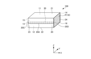
図1は、第1実施形態に係るシート包装体の斜視図であり、図2は、図1のシート包装体の右側面図であり、図3は図1のシート包装体の正面図である。実施形態のシート包装体100は、シート積層体10と包装部材20とを有する。シート包装体100は、本発明に係るシート包装体の一例であり、シート積層体10及び包装部材20は、本発明に係るシート包装体を構成するシート積層体および包装部材の一例である。
First Embodiment
Fig. 1 is a perspective view of a sheet packaging body according to a first embodiment, Fig. 2 is a right side view of the sheet packaging body of Fig. 1, and Fig. 3 is a front view of the sheet packaging body of Fig. 1. The
シート積層体10は、複数枚のシートPが積層されている。シート積層体10は、複数枚のシートPが折り畳まれてシート包装体100の高さ方向(Z方向)に積層された直方体形状の積層体を示す。直方体形状のシート積層体10は、天面11、底面12、一対の長側面13、14および一対の短側面15、16を有する(図1、図2)。
The
シート積層体10の形態は、特に限定されず、例えば、1枚(または1組)のシートPが半分に折り返され、折り返されたシートPの半分が別の折り返されたシートPに挟まれた状態で、各シートPが上下に重なるように積層されたものを用いることができる。
The form of the
このようなシート積層体10では、各シートPが折り込まれた状態で互い違いに積層されるため、シートPを1枚(または1組)引き出すと次の1枚(または1組)のシートPが引き出される。このようにシート積層体からシートが引き出される形式は、ポップアップ式と呼ばれている。なお、シートP(シート積層体10)の形態は、このようなポップアップ式に限定されず、複数枚のシートPが単に積層されたもの、1枚(または1組)のシートPが半分に折り返した後さらに半分に折り返して(4つ折りにして)重ねたものを用いてもよい。
In such a
シート積層体10は、ディスペンサー等のシートPを一枚ずつ取り出せる装置または手段に収容して使用する。ここで、ディスペンサーは、例えば、シート積層体10が収容される本体と、本体を覆う蓋部、シートPを収容する収容口と、シート積層体10が収容されたシート積層体10からシートPを取り出す取出口とを有する(図示せず)。
The
シートP(シート積層体10)の用途は、特に限定されず、ペーパータオル、ワイパー(ウエス)タオル、キッチンペーパー、ティシューペーパー、トイレットペーパー等に用いることができる。また、シートP(シート積層体10)の用途は、産業用、家庭用に限定されない。 The uses of the sheet P (sheet laminate 10) are not particularly limited, and it can be used as paper towels, wiper (rag) towels, kitchen paper, tissue paper, toilet paper, etc. Furthermore, the uses of the sheet P (sheet laminate 10) are not limited to industrial or household use.
シートPの材質は、特に限定されないが、例えば、紙、不織布または布等のシートを用いることができ、好ましくは紙シートである。なお、シートPが紙シートの場合、パルプを主原料とする原紙が用いられる。パルプ組成は、紙シートにおける公知の組成を用いることができる。例えば、パルプの配合割合を50質量%以上、好ましくは90質量%以上、より好ましくは100質量%とすることができる。 The material of the sheet P is not particularly limited, but may be, for example, a sheet of paper, nonwoven fabric, or cloth, and is preferably a paper sheet. When the sheet P is a paper sheet, base paper containing pulp as the main raw material is used. The pulp composition may be a known composition for paper sheets. For example, the pulp content may be 50% by mass or more, preferably 90% by mass or more, and more preferably 100% by mass.
また、シートP(紙シート)におけるパルプ組成は、例えば、NBKP(針葉樹クラフトパルプ)やNUKP(針葉樹未晒しパルプ)などの針葉樹パルプと、LBKP(広葉樹クラフトパルプ)やLUKP(広葉樹未晒しパルプ)などの広葉樹パルプとを任意の比率で使用することができる。特に、広葉樹パルプに対して針葉樹パルプの比率がより多いパルプ組成であることが好ましい。針葉樹パルプと広葉樹パルプの比は、50:50~80:20であるのが好ましい。なお、シートP(紙シート)のパルプ組成に含まれるパルプには、古紙パルプを用いてもよい。 The pulp composition of the sheet P (paper sheet) may be any ratio of softwood pulp such as NBKP (softwood kraft pulp) or NUKP (softwood unbleached pulp) to hardwood pulp such as LBKP (hardwood kraft pulp) or LUKP (hardwood unbleached pulp). In particular, a pulp composition having a higher ratio of softwood pulp to hardwood pulp is preferred. The ratio of softwood pulp to hardwood pulp is preferably 50:50 to 80:20. The pulp contained in the pulp composition of the sheet P (paper sheet) may be recycled paper pulp.
シートPの坪量は、特に限定されないが、プライ数に応じて、紙の場合は12~80g/m2、不織布の場合は20~100g/m2のものが好ましい。なお、坪量は、JIS P 8124の規定に準拠して測定される。 The basis weight of the sheet P is not particularly limited, but is preferably 12 to 80 g/m 2 for paper and 20 to 100 g/m 2 for nonwoven fabric, depending on the number of plies. The basis weight is measured in accordance with the provisions of JIS P 8124.
また、シートP(紙シート)の厚みは、特に限定されるものではないが、例えば、JIS P 8111(1998)の環境下で測定された紙厚を採用することができる。例えば、シートPを構成する紙シートの紙厚は、1プライあたり、好ましくは50~500μmであり、より好ましくは60~330μm程度である。 The thickness of the sheet P (paper sheet) is not particularly limited, but may be, for example, the paper thickness measured under the environment of JIS P 8111 (1998). For example, the thickness of the paper sheet constituting the sheet P is preferably 50 to 500 μm per ply, and more preferably about 60 to 330 μm.
また、シートPを構成する紙シートには、エンボス加工が施されていてもよい。このようなエンボス加工は、加圧エンボス付与方法により紙シートを押圧するもの、ピンエンボス付与方法によりピンを紙シートに刺して紙シートの一方の面上に凹凸または孔を形成するもの、ヒートエンボス付与方法により水溶性の接着剤(デンプン等)を加熱融解して積層された紙シートを接着するもの等がある。 The paper sheets constituting sheet P may also be embossed. Such embossing may be done by pressing the paper sheets using a pressure embossing method, by piercing the paper sheets with pins using a pin embossing method to form irregularities or holes on one side of the paper sheets, or by heat embossing method to heat and melt a water-soluble adhesive (such as starch) to bond the stacked paper sheets.
シートPのプライ数は、特に限定されないが、1プライ以上にすることができ、好ましくは1プライ(シングルタイプ)または2プライ(ダブルタイプまたは2枚重ね)である。なお、2プライ(2枚重ね)以上のシートPにエンボス加工を行う場合は、紙シートを2プライ(2枚重ね)にした状態でエンボスを付与してもよいし、1プライにエンボスを付与してその後2プライにしてもよい。 The number of plies of the sheet P is not particularly limited, but can be one or more, and is preferably one ply (single type) or two plies (double type or two-ply). When embossing a sheet P of two or more plies (two-ply), the embossing may be applied to the paper sheet in a two-ply state, or one ply may be embossed and then made into two plies.
また、シート積層体10の寸法は、シート包装体100の長手方向(X方向)の長さL1を150mm以上350mm以下、短手方向(Y方向)の幅W1を50mm以上150mm以下、高さ方向(Z方向)の高さH1を40mm以上150mm以下とすることができる(図2)。このようなシート積層体10は、例えば、ロータリー式又はマルチスタンド式インターフォルダによって製造することができる。
The dimensions of the
包装部材20は、シート積層体10に巻き付けられる所定の幅と長さを有する。シート包装体100では、包装部材20がシート積層体10の天面11、底面12、および一対の長側面13、14に巻き付けられた状態で、包装部材20の長手方向(シート包装体100の幅方向(Y方向))の端部20A、20Bが接合されている。これにより、シート積層体10が包装部材20によって結束されている。なお、包装部材20の接合態様は、特に限定されず、例えば、ホットメルト、ヒートシール(酢酸ビニル)、接着剤、圧着等を用いることができる。
The
本実施形態では、シート積層体10の天面11、底面12、および一対の長側面13、14は包装部材20で覆われ、シート積層体10の一対の短側面15、16は、包装部材20で覆われることなく露出する。包装部材20は、天面21がシート積層体10の天面11に対面し、底面22がシート積層体10の底面12に対面し、正面23がシート積層体10の一方の長側面13に対面し、背面24がシート積層体10の他方の長側面14に対面する(図1、図2)。
In this embodiment, the
なお、本実施形態のシート包装体100では、シート積層体10の天面11、底面12、および一対の長側面13、14が包装部材20で覆われる(シート積層体10の一対の短側面15、16は包装部材20で覆われずに露出する)が、この包装形態に限定されない。例えば、シート積層体10の天面11、底面12、および一対の短側面15、16が包装部材20で覆われる(シート積層体10の一対の長側面13、14は包装部材20で覆われずに露出する)ものでもよい。
In the
包装部材20の材質は、特に限定されない。包装部材20は、例えば、樹脂製にすることができる。ここで、樹脂製とは、材質がポリエチレン等の樹脂であることを示す。また、プラスチックの使用削減、マイクロプラスチック等の海洋汚染の抑制等の環境負荷を低減する観点から、包装部材20は紙製にするのが好ましい。ここで、紙製とは、材質が紙であることを示す。
The material of the
包装部材20に用いられる紙の材質は、特に限定されないが、例えば、シート積層体10の形態保持性、収容性の観点から、例えば、クラフト紙、フィルムラミ紙(クラフト紙とポリエチレン等の樹脂フィルムを貼合したもの)等の用紙を用いることができる。
The material of the paper used for the
包装部材20は、好ましくはクラフト紙であり、より好ましくは片艶クラフト紙である。ここで、クラフト紙は、クラフトパルプを原料とする紙である。また、片艶クラフト紙は、クラフト紙を白色まで漂白し、片面をヤンキードライヤーにて乾燥し抄紙したものである。
The
なお、片艶クラフト紙では、紙の一方の面(片側の面)は艶面を構成する。ここで、艶面は、光沢を有し、非艶面(艶面でない面)に対して摩擦抵抗が小さい面を示す。このような片艶クラフト紙を包装部材20に用いる場合、艶面がシート積層体10に対面するように包装部材20が巻き付けられていることが好ましい。
In one-sided glossy kraft paper, one side of the paper (one side) constitutes the glossy surface. Here, the glossy surface refers to a surface that has a glossy appearance and has low frictional resistance compared to the non-glossy surface (the surface that is not glossy). When using such one-sided glossy kraft paper for the
包装部材20を構成する用紙のパルプ組成は、限定されないが、例えば、0:100~80:20であり、好ましくは広葉樹パルプに対して針葉樹パルプの比率が低いパルプ組成である。また、包装部材20に含まれるパルプには、古紙パルプを用いてもよい。
The pulp composition of the paper that constitutes the
包装部材20を構成する用紙の坪量は、特に限定されず、例えば、20g/m2以上200g/m2以下である。ここで、坪量は、JIS P 8124の規定に準拠して測定することができる。また、包装部材20を構成する用紙の紙厚は、特に限定されず、例えば、20μm以上200μm以下である。ここで、紙厚は、JIS P 8111(1998)の環境下で測定することができる。
The basis weight of the paper constituting the
包装部材20を構成する用紙の強度は、縦方向の引張強度が1.5kN/m以上10kN/m以下、横方向の引張強度が1kN/m以上8kN/m以下で、縦方向の引裂強度が100mN以上1500mN以下、横方向の引裂強度が120mN以上2100mN以下である。ここで、縦方向は、用紙のMD方向を示し、横方向は、用紙のCD方向を示す。用紙の強度は、JIS P 8113(2006)の環境下で測定することができる。
The strength of the paper constituting the
なお、包装部材20を形成する用紙は、上述したクラフト紙、フィルムラミ紙の他にも、麻、非木材パルプ(バガス、ケナフ等)、生分解性材料(生分解性プラスチック、生分解性紙等)、バイオマス材料(バイオマスフィルム等の再生可能な生物由来の有機性資源で化石資源を除いたもの)を用いて製造された用紙でもよい。
In addition to the above-mentioned kraft paper and film-laminated paper, the paper forming the
なお、包装紙20をシート積層体に巻き付ける態様は、限定されない。例えば、個々のシート積層体に包装紙20を巻き付けることで、複数のシート包装体を製造することができる。また、製造コストを低減する観点から、バンドル(インターフォルダで原反を交互に折り重ねて積層したシートの集積体)に包装紙の原反を巻き付けた状態で、これを長手方向に所定の間隔で切断して、複数のシート包装体を製造してもよい。
The manner in which the
また、バンドルに包装紙の原反を巻き付けたものを長手方向に所定の間隔で切断して得られたシート包装体では、包装紙20のMD方向がシートPのCD方向となるように、包装紙20がシート積層体10に巻き付けられている。また、1枚(または1組)のシートPを4つ折りにして複数枚重ねたシート積層体に包装紙20を巻き付ける場合は、包装紙20のMD方向がシートPのCD方向となる。ここで、MD方向は、包装紙またはシートを構成する繊維の流れ方向を示す。また、CD方向は、MD方向と直交する方向を示す。
In addition, in a sheet packaging body obtained by wrapping a roll of wrapping paper around a bundle and cutting the bundle at a predetermined interval in the longitudinal direction, the wrapping
本実施形態のシート包装体100では、包装部材20は、シート積層体10に巻き付けられた状態で包装部材20の長手方向(Y方向およびZ方向)の両端部20A、20Bが重なる重畳部30を有する。包装部材20の長手方向(Y方向およびZ方向)は、包装部材20がシート積層体10に巻き付けられる巻回方向(Y方向およびZ方向)に対応する(図1~図3)。
In the
重畳部30は、第1接着部31、第2接着部32、および非接着部33を有する。
The overlapping
第1接着部31は、包装部材20記長手方向(Y方向およびZ方向)と直交する幅方向(X方向)の一方の端縁20C側から重畳部30の中央部EC側に延び、包装部材20の両端部20A、20Bを接着する。
The first
ここで、重畳部30の中央部ECは、重畳部30の中心を含み、包装部材20の幅方向(X方向)における重畳部30全体の長さの5~20%、好ましくは6~15%、より好ましくは7~10%の領域を示す。
Here, the central portion EC of the overlapping
第2接着部32は、重畳部30の中央部EC側から幅方向(X方向)の他方の端縁20D側に延び、包装部材20の両端部20A、20Bを接着する。
The second
非接着部33は、包装部材20の両端部20A、20Bが接着されない部分を構成し、第1接着部31と第2接着部32の間に位置する。本実施形態では、包装部材20の幅方向における第1接着部31の長さと第2接着部32の長さが略同一であり、非接着部33は、重畳部30の中央部ECを構成する。
The
また、重畳部30は、シート積層体10の一対の長側面13、14のいずれか一方に対面するように配置されていることが好ましい(図1)。本実施形態のシート包装体100では、重畳部30は、シート積層体10の長側面13に対面する包装部材20の正面23に設けられている。
The overlapping
第1実施形態のシート包装体100では、上述のように、包装部材20がシート積層体10に巻き付けられた状態で、包装部材20の長手方向(Y方向およびZ方向)の両端部20A、20Bが重なる重畳部30に、第1接着部31と第2接着部32の間に位置する非接着部33が設けられていることで、この非接着部33が包装部材20の開封部OPを構成することができる(図1、図3)。
In the
これにより、本実施形態では、非接着部33の外側部分33A(包装部材20の一方の端部20Aの一部)と内側部分33B(包装部材20の他方の端部20Bの一部)との間に指を入れ、この外側部分33Aを捲るだけで、包装部材20を開封することができる。そして、開封した包装部材20を破くことで、シート積層体10から包装部材20を容易に取り外すことができる。そのため、本実施形態では、シートPの補充が容易である。
As a result, in this embodiment, the
また、本実施形態では、シート積層体10の天面11、底面12、および一対の長側面13、14のみに包装部材20が巻き付けられている(シート積層体10の一対の短側面15、16は露出する)ことで、シート積層体10の全体が包装部材20で覆われていないため、包装部材20の使用量を削減することができる。
In addition, in this embodiment, the
また、第1実施形態のシート包装体100では、上述のように、シート積層体10の一対の長側面13、14のいずれか一方(本実施形態では長側面13)に対面するように重畳部30が包装部材20に設けられていることで、破れやすい非接着部33はシート包装体100が輸送時または保管時に重なりやすいシート積層体10の天面11及び底面12(包装部材20の天面21及び底面22)に対面しない。
In addition, in the
そのため、本実施形態では、シート包装体100の輸送時または保管時に開封部OPを構成する非接着部33の予期せぬ開封を防ぐことができる。また、本実施形態では、開封部OPを構成する非接着部33がシート包装体100の見えやすい位置に設けられているため、包装部材の開封が容易である。
Therefore, in this embodiment, it is possible to prevent the unintentional opening of the
<第2実施形態>
図4は、第2実施形態に係るシート包装体の正面図である。なお、図4において、第1実施形態(図3)と共通する部分には、図3と同一又は対応する符号を付して説明を省略する。
Second Embodiment
Fig. 4 is a front view of a sheet wrapping body according to the second embodiment. In Fig. 4, parts common to the first embodiment (Fig. 3) are denoted by the same or corresponding reference numerals as in Fig. 3, and description thereof will be omitted.
第2実施形態のシート包装体100では、非接着部33の外側部分33Aに、外側部分33Aの端縁AEから包装部材20の長手方向(Y方向およびZ方向)に延びる開裂用切目線40が形成されている。ここで、外側部分33Aの端縁AEは、非接着部33の外側部分33Aを構成する包装部材20の一方の端部20Aの一部の端縁に対応する。
In the second embodiment of the
開裂用切目線40は、カットCとタイT(2つのカットC、C間のカットされていない部分)が交互に配置され、タイTが破断すると両隣のカットC、Cが連続したカットになる切目線(例えば、ミシン目M)である。
The tearing
なお、開裂用切目線40の予期せぬ開裂を防ぎながら、開裂用切目線40を開裂しやすくする観点から、開裂用切目線40のカット率(タイTに対するカットCの比率)は、60~90%であることが好ましく、より好ましくは65~88%、さらに好ましくは70~86%である。
In order to prevent the tearing
第2実施形態では、開裂用切目線40が一対の開裂用切目線41、42で構成されている。一対の開裂用切目線41、42は、包装部材20の幅方向(X方向)における重畳部30の中央部ECの長さと略同じ間隔で配置され、包装部材20の幅方向(X方向)と直交する(垂直な)方向に延びる。
In the second embodiment, the tearing
本実施形態では、開裂用切目線40(一対の開裂用切目線41、42)は、包装部材20の正面23のみに形成されているが、これに限定されず、包装部材20の正面23から天面21まで連続して形成されていてもよい。
In this embodiment, the tearing score line 40 (a pair of tearing
第2実施形態のシート包装体100では、このように、非接着部33の外側部分33Aの端縁AEから包装部材20の長手方向(Y方向およびZ方向)に延びる開裂用切目線40が非接着部33の外側部分33Aに形成されていることで、非接着部33を介して包装部材20を開封した後、さらに開裂用切目線40に沿って包装部材20を容易に破ることができる。そのため、本実施形態では、シート積層体10からの包装部材20の取り外しがさらに容易になる。
In the
<第3実施形態>
図5は、第3実施形態に係るシート包装体の正面図である。なお、図5において、第1実施形態(図3)、および第2実施形態(図4)と共通する部分には、図3、図4と同一又は対応する符号を付して説明を省略する。
Third Embodiment
Fig. 5 is a front view of a sheet wrapping body according to a third embodiment. In Fig. 5, parts common to the first embodiment (Fig. 3) and the second embodiment (Fig. 4) are denoted by the same or corresponding reference numerals as in Figs. 3 and 4, and description thereof will be omitted.
第3実施形態のシート包装体100では、非接着部33の外側部分33Aに、外側部分33Aの端縁AEから包装部材20の長手方向(Y方向およびZ方向)に末広がりに延びる開裂用切目線40(一対の開裂用切目線41、42)が形成されている。
In the third embodiment of the
包装部材20の長手方向(Y方向およびZ方向)に末広がりに延びる一対の開裂用切目線41、42は、一対の開裂用切目線41、42間の包装部材20の幅方向(X方向)における距離が長くなるように、一対の開裂用切目線41、42が包装部材20の長手方向(Y方向およびZ方向)に延びる。本実施形態では、一対の開裂用切目線41、42は、包装部材20の正面23に形成され、包装部材20の底面22側から天面21側に向かって末広がりに延びる。
The pair of tearing
第3実施形態のシート包装体100では、このように非接着部33の外側部分33Aに形成された一対の開裂用切目線40(開裂用切目線41、42)が、非接着部33の外側部分33Aの端縁AEから包装部材20の長手方向(Y方向およびZ方向)に末広がりに延びることで、開裂用切目線40(開裂用切目線41、42)に沿って包装部材20を破るときの開裂線(図示せず)が包装部材20の幅方向(X方向)の両端縁20C、20Dに繋がりやすくなる。
In the third embodiment of the
これにより、包装部材20を破った後の破断片(図示せず)が複数になるのを防ぐことができる(破断片を1つにすることができる)。そのため、第3実施形態のシート包装体100では、シート積層体10から取り外した包装部材20の処理が容易である。
This prevents the
<第4実施形態>
図6は、第4実施形態に係るシート包装体の正面図である。なお、図6において、第1実施形態(図3)、第2実施形態(図4)、および第3実施形態(図5)と共通する部分には、図3~図5と同一又は対応する符号を付して説明を省略する。
Fourth Embodiment
Fig. 6 is a front view of a sheet packaging body according to the fourth embodiment. In Fig. 6, parts common to the first embodiment (Fig. 3), the second embodiment (Fig. 4), and the third embodiment (Fig. 5) are denoted by the same or corresponding reference numerals as in Figs. 3 to 5, and description thereof will be omitted.
第4実施形態のシート包装体100では、開裂用切目線40(ミシン目M)のうち一方の開裂用切目線41を構成するカット50が、直線状の基部51と、延長部52を有し、他方の開裂用切目線42を構成するカット60が、直線状の基部61と、延長部62を有する(図6)。
In the fourth embodiment of the
直線状の基部51、61は、一方の開裂用切目線41を構成するカットの基部51と、他方の開裂用切目線42を構成するカットの基部61とが、外側部分33Aの端縁AE側から包装部材20の長手方向(Y方向およびZ方向)に末広がりに延びるように配置されて構成されている(図6)。
The
延長部52は、基部51の外側部分33Aの端縁AE側の一端から包装部材20の幅方向(X方向)に対向する開裂用切目線42(延長部62)側に延びる(図6、図7)。また、延長部62は、基部61の外側部分33Aの端縁AE側の一端から包装部材20の幅方向(X方向)に対向する開裂用切目線41(延長部52)側に延びる(図6、図8)。
The
一方の開裂用切目線41を構成するカット50の延長部52と、他方の開裂用切目線42を構成するカット60の延長部62とは、互いに一対の開裂用切目線40(一対の開裂用切目線41、42)の内側に延びる。
The
このように、開裂用切目線41のカット50は、外側部分33Aの端縁AEから包装部材20の長手方向(Y方向およびZ方向)に末広がりに延びる基部51に対して延長部52が鈍角に曲がるL字状となる(図6、図7)。また、開裂用切目線42のカット60は、外側部分33Aの端縁AEから包装部材20の長手方向(Y方向およびZ方向)に末広がりに延びる基部61に対して延長部62が鈍角に曲がるL字状となる(図6、図8)。
In this way, the
第4実施形態のシート包装体100では、開裂用切目線40(一対の開裂用切目線41、42)を構成するカット50、60がこのような基部51、61と延長部52、62を有することで、開裂用切目線40に沿って包装部材20を破るときの開裂線(図示せず)は、末広がりに延びる一対の開裂用切目線41、42の内側に逸れた場合でも、隣のカット50、60の延長部52、62に繋がり、基部51、61が延びる方向(開裂用切目線41、42が延びる方向)に戻ることができる。そのため、非接着部33の外側部分33Aの端縁AEから包装部材20の長手方向(Y方向およびZ方向)に末広がりに延びる開裂用切目線41、42に沿って確実に包装部材20を破ることができる。
In the fourth embodiment of the
<第5実施形態>
図9は、第5実施形態に係るシート包装体の正面図である。なお、図9において、第1実施形態(図3)、第2実施形態(図4)、第3実施形態(図5)、および第4実施形態(図6)と共通する部分には、図3~図6と同一又は対応する符号を付して説明を省略する。
Fifth Embodiment
Fig. 9 is a front view of a sheet packaging body according to the fifth embodiment. In Fig. 9, parts common to the first embodiment (Fig. 3), the second embodiment (Fig. 4), the third embodiment (Fig. 5), and the fourth embodiment (Fig. 6) are denoted by the same or corresponding reference numerals as in Figs. 3 to 6, and description thereof will be omitted.
第5実施形態のシート包装体100では、包装部材20の幅方向(X方向)における第1接着部31の長さと第2接着部32の長さが異なり、非接着部33が、包装部材20の幅方向(X方向)の一方の端縁20C寄りまたは他方の端縁20D寄りに位置する。なお、図9に示す第5実施形態の例では、非接着部33が、包装部材20の幅方向(X方向)の一方の端縁20C寄りに位置し、第4実施形態の開裂用切目線40(カット50、60が直線状の基部51、61と延長部52、62を有する開裂用切目線41、42)が設けられている。
In the
なお、第1接着部31の長さと第2接着部32の長さが異なる場合は、第1接着部31の長さが第2接着部32の長さよりも短い場合と、第1接着部31の長さが第2接着部32の長さよりも長い場合がある。本実施形態では、第1接着部31の長さが第2接着部32の長さよりも短くなっている(図9)。
When the length of the first
また、包装部材20の幅方向(X方向)の一方の端縁20C寄りは、包装部材20の幅方向(X方向)の一方の端縁20Cと重畳部30の中央部ECとの間の領域NEを示す(図6)。また、包装部材20の幅方向(X方向)の他方の端縁20D寄りは、包装部材20の幅方向(X方向)の他方の端縁20Dと重畳部30の中央部ECとの間の領域を示す(図示せず)。本実施形態では、包装部材20の幅方向(X方向)の一方の端縁20C寄り(領域NE)に非接着部33が設けられている。
The area near one
第5実施形態のシート包装体100では、このように非接着部33が包装部材20の幅方向(X方向)の一方の端縁20C寄りまたは他方の端縁20D寄りに位置することで、非接着部33を介して包装部材20を開封し、さらに包装部材20を破ったときの開裂線(図示せず)が包装部材20の幅方向(X方向)の一方の端縁20Cまたは他方の端縁20Dに繋がりやすくなる。そのため、包装部材20を破った後の破断片(図示せず)が複数になるのを抑制することができる。また、シート積層体10からの包装部材20の取り外しが容易であり、シートPの補充が容易である。
In the fifth embodiment of the
以下、本発明について、さらに実施例を用いて具体的に説明する。実施例、比較例の評価は、以下の条件で行った。シート包装体の条件および評価結果を表1、表2に示す。 The present invention will now be described in more detail with reference to examples. The evaluations of the examples and comparative examples were carried out under the following conditions. The conditions of the sheet packaging and the evaluation results are shown in Tables 1 and 2.
[シート包装体(サンプル)]
シートPが交互に折り畳まれてポップアップ式に1組ずつ引き出せるように積層されたシート積層体10としてペーパータオル(大王製紙社製、エリエール PAPER TOWEL スマートタイプ シングル、200枚、シート寸法:縦170mm、横210mm)の天面11、底面12、一対の長側面13、14を、包装部材20(幅210mm)で巻き付け包装したシート包装体100を用意した。包装部材20は、シート積層体10に巻き付けられた状態で包装部材20の長手方向(Y方向およびZ方向)の両端部20A、20Bが重なる重畳部30を、シート積層体10の長側面13に対面する包装部材20の正面23に設けた。
[Sheet packaging (sample)]
A
[開封性]
シート包装体100(サンプル)を包装部材20の重畳部30から開封したときの開封性を評価した。開封性は、6段階で評価し、最も開封しにくい場合を「0」、最も開封しやすい場合を「6」と評価した。なお、評価が1以上の場合は良好と判定し、0の場合は不良と判定する。
[Openability]
The sheet packaging body 100 (sample) was evaluated for ease of opening when it was opened from the overlapping
[実施例1]
包装部材20の材質を紙(米坪が40g/m2のクラフト紙)とし(紙包装)、重畳部30の中央(中央部EC)に開封部OP(非接着部33)を設けた(図1~図3参照)。実施例1の条件および評価結果を表1に示す。
[Example 1]
The material of the
[実施例2]
非接着部33の外側部分33Aに、外側部分33Aの端縁AEから包装部材20の幅方向(X方向)と直交する(垂直な)方向に延びる開裂用切目線40を、包装部材20の幅方向(X方向)における重畳部30の中央部ECの長さと略同じ間隔の直線のミシン目M(一対の開裂用切目線41、42)で形成し、開裂用切目線40(ミシン目M)のカット率を75.0%(カットの長さ3mm、タイの長さ1mm)とした以外は、実施例1と同様にした(図4参照)。実施例2の条件および評価結果を表1に示す。
[Example 2]
In the
[実施例3]
開裂用切目線40を、外側部分33Aの端縁AEから包装部材20の長手方向(Y方向およびZ方向)に末広がりに延びるミシン目M(一対の開裂用切目線41、42)で形成した以外は、実施例2と同様にした(図5参照)。実施例3の条件および評価結果を表1に示す。
[Example 3]
The same procedure as in Example 2 was followed (see FIG. 5 ), except that the tearing
[実施例4]
開裂用切目線40を、L字状のミシン目M(カット50、60が、直線状の基部51、61と延長部52、62を有する一対の開裂用切目線41、42)で形成し、開裂用切目線40(ミシン目M)のカット率を85.7%(カットの長さ6mm、タイの長さ1mm)とした以外は、実施例3と同様にした(図6~図8参照)。実施例4の条件および評価結果を表1に示す。
[Example 4]
The tearing
[実施例5]
開封部OP(非接着部33)を、包装部材20の幅方向(X方向)の一方の端縁20C寄り(端)に設けた以外は、実施例4と同様にした(図9参照)。実施例5の条件および評価結果を表1に示す。
[Example 5]
The same procedure was followed as in Example 4, except that the opening portion OP (non-adhesive portion 33) was provided near one
[比較例1]
開封部OP(非接着部33)を形成しなかった以外は、実施例1と同様にした(図10参照)。比較例1の条件および評価結果を表1に示す。
[Comparative Example 1]
The comparative example 1 was carried out in the same manner as in Example 1, except that the opening portion OP (non-adhesive portion 33) was not formed (see FIG. 10). The conditions and evaluation results of the comparative example 1 are shown in Table 1.
[実施例6]
包装部材20の材質を紙(米坪が30g/m2のクラフト紙)に膜厚15μmのポリエチレン(PE)層を設けたもの(紙+PE包装)とした以外は、実施例1と同様にした(図1~図3参照)。実施例6の条件および評価結果を表2に示す。
[Example 6]
The same procedure was followed as in Example 1, except that the material of the
[実施例7]
包装部材20の材質を紙+PE包装とした以外は、実施例2と同様にした(図4参照)。実施例7の条件および評価結果を表2に示す。
[実施例8]
包装部材20の材質を紙+PE包装とした以外は、実施例3と同様にした(図5参照)。実施例8の条件および評価結果を表2に示す。
[Example 7]
The conditions and evaluation results of Example 7 are shown in Table 2. Example 7 was carried out in the same manner as Example 2, except that the material of the
[Example 8]
The conditions and evaluation results of Example 8 are shown in Table 2. Example 8 was conducted in the same manner as Example 3, except that the material of the
[実施例9]
包装部材20の材質を紙+PE包装とした以外は、実施例4と同様にした(図6~図8参照)。実施例9の条件および評価結果を表2に示す。
[Example 9]
The conditions and evaluation results of Example 9 are shown in Table 2. Example 9 was conducted in the same manner as in Example 4, except that the material of the
[実施例10]
包装部材20の材質を紙+PE包装とした以外は、実施例5と同様にした(図9参照)。実施例10の条件および評価結果を表2に示す。
[Example 10]
The conditions and evaluation results of Example 10 are shown in Table 2. Example 10 was carried out in the same manner as Example 5, except that the material of the
[比較例2]
包装部材20の材質を紙+PE包装とした以外は、比較例1と同様にした(図10参照)。比較例2の条件および評価結果を表2に示す。
[Comparative Example 2]
The comparative example was the same as the comparative example 1 except that the material of the


表1、2より、包装部材20がシート積層体10に巻き付けられた状態で、包装部材20の長手方向(Y方向およびZ方向)の両端部20A、20Bが重なる重畳部30に、第1接着部31と第2接着部32の間に位置する非接着部33が設けられたシート包装体100(サンプル)は、いずれも開封性が良好であった(実施例1~10)。
As can be seen from Tables 1 and 2, when the
また、包装部材20に開裂用切目線40が設けられたシート包装体100は、開封性が向上した(実施例2~5、7~10)。
In addition, the
さらに、開裂用切目線40が外側部分33Aの端縁AEから包装部材20の長手方向(Y方向およびZ方向)に末広がりに延びるシート包装体100は、開封性がさらに向上した(実施例3~5、8~10)。
Furthermore, the
さらに、開裂用切目線40(開裂用切目線41、42)のカット50、60が、外側部分33Aの端縁AEから包装部材20の長手方向(Y方向およびZ方向)に末広がりに延びる基部51、61に対して延長部52、62が鈍角に曲がるL字状となるシート包装体100は、開封性がさらに向上した(実施例4~5、9~10)。
Furthermore, the
一方、包装部材20の長手方向(Y方向およびZ方向)の両端部20A、20Bが重なる重畳部30に、非接着部33が設けられていないシート包装体は、開封性がいずれ不良であった(比較例1、2)。
On the other hand, sheet packages in which the overlapping
以上、本発明の実施形態について説明したが、本発明は特定の実施形態に限定されるものではなく、特許請求の範囲に記載された発明の範囲内において、種々の変形、変更が可能である。 Although the embodiment of the present invention has been described above, the present invention is not limited to a specific embodiment, and various modifications and variations are possible within the scope of the invention described in the claims.
100 シート包装体
10 シート積層体
P シート
11 天面
12 底面
13 長側面
14 長側面
15 短側面
16 短側面
20 包装部材
20A 端部
20B 端部
21 天面
22 底面
23 正面
24 背面
30 重畳部
31 第1接着部
32 第2接着部
33 非接着部
OP 開封部
33A 外側部分
AE 端縁
NE 領域
33B 内側部分
40、41、42 開裂用切目線
M ミシン目
C カット
T タイ
50 カット
51 基部
52延長部
60 カット
61 基部
62延長部
100
Claims (6)
前記シート積層体の天面、底面、および対向する一対の側面に巻き付けられた包装部材と、を有し、
前記包装部材は、前記シート積層体に巻き付けられた状態で前記包装部材の長手方向の両端部が重なる重畳部を有し、
前記重畳部は、
前記包装部材の前記両端部を接着して、前記包装部材の前記長手方向と直交する幅方向の一方の端縁側から前記重畳部の中央部側に延びる第1接着部と、
前記包装部材の前記両端部を接着して、前記重畳部の前記中央部側から前記幅方向の他方の端縁側に延びる第2接着部と、
前記第1接着部と前記第2接着部の間に位置して、前記両端部が接着されない非接着部と、を有する、
シート包装体。 a rectangular parallelepiped sheet laminate in which a plurality of sheets are laminated;
a packaging material wrapped around the top surface, the bottom surface, and a pair of opposing side surfaces of the sheet laminate;
the packaging material has an overlapping portion where both ends of the packaging material in the longitudinal direction overlap each other when the packaging material is wrapped around the sheet stack,
The overlapping portion is
a first adhesive portion that bonds the both end portions of the packaging member and extends from one end edge side in a width direction perpendicular to the longitudinal direction of the packaging member toward a center portion side of the overlapping portion;
a second adhesive portion that adheres the both end portions of the packaging member to each other and extends from the center side of the overlapping portion to the other end edge side in the width direction;
a non-adhesive portion located between the first adhesive portion and the second adhesive portion, and the both ends are not adhered to each other;
Sheet packaging.
請求項1に記載のシート包装体。 A tearing score line is formed on an outer portion of the non-adhesive portion, the tearing score line extending from an edge of the outer portion in the longitudinal direction of the packaging member.
The sheet packaging body according to claim 1 .
請求項1に記載のシート包装体。 A pair of tearing score lines are formed on an outer portion of the non-adhesive portion, the tearing score lines extending from an edge of the outer portion in a divergent manner in the longitudinal direction of the packaging material.
The sheet packaging body according to claim 1 .
直線状に延びる基部と、
前記基部の前記外側部分の前記端縁側の一端から前記包装部材の前記幅方向に対向する前記開裂用切目線側に延びる延長部と、を有する、
請求項3に記載のシート包装体。 The cut constituting the cleavage score line is
A linearly extending base;
an extension portion extending from one end of the outer portion of the base toward the tearing score line facing the width direction of the packaging material,
The sheet packaging body according to claim 3.
請求項1乃至4のいずれか一項に記載のシート包装体。 The overlapping portion is arranged to face one of the pair of side surfaces of the sheet laminate.
The sheet packaging body according to any one of claims 1 to 4.
前記非接着部が、前記包装部材の前記幅方向の前記一方の端縁寄りまたは前記他方の端縁寄りに位置する、
請求項1乃至4のいずれか一項に記載のシート包装体。 a length of the first adhesive portion and a length of the second adhesive portion are different in a width direction of the packaging member,
the non-adhesive portion is located near the one edge or the other edge in the width direction of the packaging member;
The sheet packaging body according to any one of claims 1 to 4.
Priority Applications (1)
| Application Number | Priority Date | Filing Date | Title |
|---|---|---|---|
| JP2023030950A JP2024123491A (en) | 2023-03-01 | 2023-03-01 | Sheet packaging |
Applications Claiming Priority (1)
| Application Number | Priority Date | Filing Date | Title |
|---|---|---|---|
| JP2023030950A JP2024123491A (en) | 2023-03-01 | 2023-03-01 | Sheet packaging |
Publications (1)
| Publication Number | Publication Date |
|---|---|
| JP2024123491A true JP2024123491A (en) | 2024-09-12 |
Family
ID=92676646
Family Applications (1)
| Application Number | Title | Priority Date | Filing Date |
|---|---|---|---|
| JP2023030950A Pending JP2024123491A (en) | 2023-03-01 | 2023-03-01 | Sheet packaging |
Country Status (1)
| Country | Link |
|---|---|
| JP (1) | JP2024123491A (en) |
-
2023
- 2023-03-01 JP JP2023030950A patent/JP2024123491A/en active Pending
Similar Documents
| Publication | Publication Date | Title |
|---|---|---|
| KR102938077B1 (en) | Sheet packaging | |
| JP7224121B2 (en) | Sanitary thin paper package | |
| JP7221730B2 (en) | sheet package | |
| JP2021160814A (en) | Home-use roll paper packaging body | |
| JP7673341B2 (en) | Packaging bag, manufacturing method thereof, and sheet packaging body | |
| JP2024123491A (en) | Sheet packaging | |
| JP7646978B2 (en) | Sheet packaging | |
| JP2024123490A (en) | Sheet packaging | |
| JP7513479B2 (en) | Sheet bundle | |
| JP2024123492A (en) | Sheet packaging | |
| JP7513536B2 (en) | Sheet packaging | |
| JP7492883B2 (en) | Sheet bundle | |
| JP7574778B2 (en) | Sanitary tissue product packaging | |
| JP2024123493A (en) | Sheet packaging | |
| JP2020138787A (en) | Sheet packaging | |
| JP2023128142A (en) | Packaging bags and sheet packaging | |
| JP7403278B2 (en) | sheet packaging | |
| JP7740096B2 (en) | packaging | |
| JP7812636B2 (en) | Sheet packaging | |
| JP7558727B2 (en) | Sheet bundle and belt-shaped member | |
| JP7838210B2 (en) | packaging box | |
| JP7552978B2 (en) | Sheet holder | |
| JP7521514B2 (en) | Sanitary tissue product packaging | |
| JP7812632B2 (en) | Packaging bag and sheet packaging body | |
| JP7729533B2 (en) | Packaging bag and sheet packaging body |
Legal Events
| Date | Code | Title | Description |
|---|---|---|---|
| A621 | Written request for application examination |
Free format text: JAPANESE INTERMEDIATE CODE: A621 Effective date: 20260113 |