JP2024102422A - Protective film forming apparatus, judgment method, and protective film forming method - Google Patents
Protective film forming apparatus, judgment method, and protective film forming method Download PDFInfo
- Publication number
- JP2024102422A JP2024102422A JP2023006279A JP2023006279A JP2024102422A JP 2024102422 A JP2024102422 A JP 2024102422A JP 2023006279 A JP2023006279 A JP 2023006279A JP 2023006279 A JP2023006279 A JP 2023006279A JP 2024102422 A JP2024102422 A JP 2024102422A
- Authority
- JP
- Japan
- Prior art keywords
- holding
- protective film
- workpiece
- holding surface
- light
- Prior art date
- Legal status (The legal status is an assumption and is not a legal conclusion. Google has not performed a legal analysis and makes no representation as to the accuracy of the status listed.)
- Pending
Links
Images



Landscapes
- Coating Apparatus (AREA)
- Dicing (AREA)
- Container, Conveyance, Adherence, Positioning, Of Wafer (AREA)
Abstract
【課題】保持テーブルの保持面に樹脂片が付着しているか否かを適切に判定できる保護膜形成装置を提供する。【解決手段】保護膜形成装置は、保持テーブルと、保護膜形成ユニットと、光源と、撮像ユニットと、洗浄ユニットと、コントローラと、を含む。コントローラは、保持テーブルの保持面が被加工物を保持していない状態で、光源に光を放射させ、光源が光を放射している状態で、被加工物を保持していない状態の保持面を撮像ユニットに撮像させて保持面が写った画像を取得し、画像に基づいて保持面に樹脂を含む樹脂片が付着しているか否かを判定する。【選択図】図3[Problem] To provide a protective film forming device that can appropriately determine whether or not resin pieces are attached to the holding surface of a holding table. [Solution] The protective film forming device includes a holding table, a protective film forming unit, a light source, an imaging unit, a cleaning unit, and a controller. The controller causes the light source to emit light when the holding surface of the holding table is not holding a workpiece, and while the light source is emitting light, causes the imaging unit to capture an image of the holding surface when no workpiece is being held, obtaining an image of the holding surface, and determines whether or not resin pieces containing resin are attached to the holding surface based on the image. [Selected Figure] Figure 3
Description
本発明は、樹脂を含む保護膜を被加工物に形成する際に用いられる保護膜形成装置、保護膜形成装置で使用される判定方法、及び判定方法を含む保護膜形成方法に関する。 The present invention relates to a protective film forming device used when forming a protective film containing a resin on a workpiece, a determination method used in the protective film forming device, and a protective film forming method including the determination method.
半導体ウェーハのような板状の被加工物を複数のチップへと分割する方法として、被加工物にレーザービームを照射して、その被照射領域を部分的に溶融、蒸発させるレーザーアブレーションと呼ばれる加工方法が知られている(例えば、特許文献1参照)。このレーザーアブレーションでは、レーザービームによって溶融、蒸発した被加工物の一部が周囲に飛散してデブリ(加工屑)となり、被加工物の上面等に付着し易い。 As a method for dividing a plate-shaped workpiece such as a semiconductor wafer into multiple chips, a processing method called laser ablation is known in which the workpiece is irradiated with a laser beam to partially melt and evaporate the irradiated area (see, for example, Patent Document 1). In this laser ablation method, parts of the workpiece that are melted and evaporated by the laser beam scatter into the surrounding area and become debris (processing waste), which tends to adhere to the top surface of the workpiece, etc.
そこで、近年では、被加工物の上面に水溶性の保護膜を形成し、この保護膜を介して被加工物にレーザービームを照射する加工方法が提案されている(例えば、特許文献2参照)。この加工方法では、レーザーアブレーションによって発生したデブリが保護膜に付着し、後の洗浄の工程において保護膜とともに洗い流されるので、被加工物の上面等にデブリが付着する可能性は低くなる。 In recent years, a processing method has been proposed in which a water-soluble protective film is formed on the top surface of the workpiece, and the workpiece is irradiated with a laser beam through this protective film (see, for example, Patent Document 2). In this processing method, debris generated by laser ablation adheres to the protective film and is washed away together with the protective film in a subsequent cleaning process, reducing the possibility of debris adhering to the top surface, etc., of the workpiece.
被加工物の上面に水溶性の保護膜を形成する際には、例えば、被加工物の下面側を保持する保持面を有し回転駆動源に接続された保持テーブルと、保護膜の原料となる液状の樹脂を被加工物の上面に供給するノズルと、を含む保護膜形成装置が用いられる。ノズルから被加工物に液状の樹脂を滴下し、保持テーブルを被加工物とともに回転駆動源で回転させて液状の樹脂を薄く広げ、この液状の樹脂を乾燥させることで、被加工物の上面に水溶性の保護膜が形成される。 When forming a water-soluble protective film on the top surface of a workpiece, for example, a protective film forming device is used that includes a holding table that has a holding surface that holds the bottom side of the workpiece and is connected to a rotary drive source, and a nozzle that supplies liquid resin, which is the raw material for the protective film, to the top surface of the workpiece. Liquid resin is dropped onto the workpiece from the nozzle, and the holding table together with the workpiece is rotated by the rotary drive source to spread the liquid resin thinly, and this liquid resin is dried, forming a water-soluble protective film on the top surface of the workpiece.
ところで、上述した保持テーブルの保持面には、様々な原因で液状の樹脂が付着し、この液状の樹脂が乾燥した樹脂片が保持面に残ってしまうことがある。樹脂片が保持面に付着して残った状態の保持テーブルで被加工物の下面側が保持されると、被加工物の上面が傾き、均一な厚みの保護膜が形成されなくなる。保護膜の厚みの均一性が低下すると、レーザーアブレーションの際に被加工物が十分に保護されない。 However, liquid resin can adhere to the holding surface of the holding table mentioned above for various reasons, and when this liquid resin dries, pieces of resin can remain on the holding surface. If the underside of the workpiece is held by a holding table with pieces of resin remaining on the holding surface, the top surface of the workpiece will tilt, and a protective film of uniform thickness will not be formed. If the uniformity of the thickness of the protective film decreases, the workpiece will not be adequately protected during laser ablation.
よって、本発明の目的は、保持テーブルの保持面に樹脂片が付着しているか否かを適切に判定できる保護膜形成装置、この保護膜形成装置で使用される判定方法、及びこの判定方法を含む保護膜形成方法を提供することである。 Therefore, the object of the present invention is to provide a protective film forming device that can properly determine whether or not resin pieces are attached to the holding surface of a holding table, a determination method used in this protective film forming device, and a protective film forming method that includes this determination method.
本発明の一側面によれば、第1面と、該第1面とは反対側の第2面と、を有する被加工物の該第1面に樹脂を含む保護膜を形成する保護膜形成装置であって、該被加工物の該第2面を保持する保持面を有し、回転駆動源に接続された保持テーブルと、該保護膜の原料となる液状の樹脂を供給する樹脂供給ノズルを有し、該保持テーブルの該保持面により保持された該被加工物の該第1面に該液状の樹脂を塗布して該保護膜を形成する保護膜形成ユニットと、該保持テーブルの該保持面の上方から該保持面へと向けて光を放射する光源と、受光素子を有し、該保持テーブルの該保持面の上方から該保持テーブルの該保持面側を撮像して画像を形成する撮像ユニットと、洗浄用の流体を供給する洗浄ノズルを有し、該保持テーブルの該保持面を洗浄する洗浄ユニットと、処理装置と記憶装置とを有し、該記憶装置に記憶されているプログラムに従い該処理装置が動作することにより該光源及び該撮像ユニットの動作を制御するコントローラと、を含み、該コントローラは、該プログラムに従い、該保持テーブルの該保持面が該被加工物を保持していない状態で、該光源に該光を放射させ、該光源が該光を放射している状態で、該被加工物を保持していない状態の該保持面を該撮像ユニットに撮像させて該保持面が写った画像を取得し、該画像に基づいて該保持面に該樹脂を含む樹脂片が付着しているか否かを判定する保護膜形成装置が提供される。 According to one aspect of the present invention, a protective film forming device for forming a protective film containing resin on a first surface of a workpiece having a first surface and a second surface opposite to the first surface includes a holding surface for holding the second surface of the workpiece and a holding table connected to a rotary drive source, a resin supply nozzle for supplying liquid resin as a raw material for the protective film, and a protective film forming unit for applying the liquid resin to the first surface of the workpiece held by the holding surface of the holding table to form the protective film, a light source for emitting light from above the holding surface of the holding table toward the holding surface, an imaging unit having a light receiving element and imaging the holding surface side of the holding table from above the holding surface of the holding table to form an image, and a cleaning device. The protective film forming device includes a cleaning unit that has a cleaning nozzle that supplies a fluid and cleans the holding surface of the holding table, and a controller that has a processing device and a storage device and controls the operation of the light source and the imaging unit by operating the processing device according to a program stored in the storage device, and the controller, according to the program, causes the light source to radiate the light when the holding surface of the holding table is not holding the workpiece, and causes the imaging unit to capture an image of the holding surface when the light source is radiating the light, and determines whether or not resin pieces containing the resin are attached to the holding surface based on the image.
好ましくは、該光源は、該保護膜に吸収される波長の該光を放射し、該撮像ユニットの該受光素子は、該光を吸収した該保護膜が発する光の波長に感度を持つ。また、好ましくは、該保持面に該樹脂片が付着していると判定された場合に、該コントローラは、該プログラムに従い、該洗浄ユニットに該保持面を洗浄させる。 Preferably, the light source emits light of a wavelength that is absorbed by the protective film, and the light receiving element of the imaging unit is sensitive to the wavelength of light emitted by the protective film that has absorbed the light. Also, preferably, when it is determined that the resin piece is attached to the holding surface, the controller causes the cleaning unit to clean the holding surface according to the program.
本発明の別の一側面によれば、被加工物を保持する保持面を有する保持テーブルの該保持面に該被加工物の保護膜に含まれる樹脂を含む樹脂片が付着しているか否かを判定する判定方法であって、該保持テーブルの該保持面が該被加工物を保持していない状態で、該保持面の上方の光源から該保持面へと向けて光を放射し、該光源が該光を放射している状態で、該被加工物を保持していない状態の該保持面を撮像ユニットで撮像して該保持面が写った画像を取得し、該画像に基づき該保持面に該樹脂片が付着しているか否かを判定する判定方法が提供される。 According to another aspect of the present invention, there is provided a method for determining whether or not a resin piece, including a resin contained in a protective film of a workpiece, is attached to the holding surface of a holding table having a holding surface for holding a workpiece, the method comprising: emitting light from a light source above the holding surface toward the holding surface when the holding surface of the holding table is not holding the workpiece; capturing an image of the holding surface when the light source is emitting the light using an imaging unit; and determining whether or not the resin piece is attached to the holding surface based on the image.
好ましくは、該光源は、該保護膜に吸収される波長の該光を放射し、該撮像ユニットは、該光を吸収した該保護膜が発する光の波長に感度を持つ受光素子を有する。また、好ましくは、該保持面に該樹脂片が付着していると判定された場合に、洗浄ユニットにより該保持面を洗浄する。 Preferably, the light source emits light of a wavelength that is absorbed by the protective film, and the imaging unit has a light receiving element that is sensitive to the wavelength of light emitted by the protective film that has absorbed the light. Also, preferably, when it is determined that the resin pieces are attached to the holding surface, the holding surface is cleaned by a cleaning unit.
本発明の更に別の一側面によれば、上述の判定方法を含む保護膜形成方法であって、該保持面に該樹脂片が付着していると判定された場合であって該洗浄ユニットにより該保持面が洗浄された後に、又は、該保持面に該樹脂片が付着していないと判定された場合に、第1面と、該第1面とは反対側の第2面と、を有する該被加工物の該第2面を該保持テーブルの該保持面により保持し、該保持テーブルの該保持面により保持された該被加工物の該第1面に該保護膜の原料となる液状の樹脂を塗布して該保護膜を形成する保護膜形成方法が提供される。 According to yet another aspect of the present invention, there is provided a protective film forming method including the above-mentioned determination method, in which, when it is determined that the resin pieces are attached to the holding surface and after the holding surface has been cleaned by the cleaning unit, or when it is determined that the resin pieces are not attached to the holding surface, the second surface of the workpiece having a first surface and a second surface opposite to the first surface is held by the holding surface of the holding table, and a liquid resin that is a raw material for the protective film is applied to the first surface of the workpiece held by the holding surface of the holding table to form the protective film.
本発明の一側面にかかる保護膜形成装置等は、保持テーブルの保持面が被加工物を保持していない状態で、保持面の上方の光源から保持面へと向けて光を放射し、次に、被加工物を保持していない状態の保持面を撮像ユニットに撮像させて保持面が写った画像を取得し、その後、画像に基づいて保持面に樹脂片が付着しているか否かを判定するので、保持テーブルの保持面に樹脂片が付着しているか否かを適切に判定できる。 In one aspect of the present invention, a protective film forming device or the like emits light from a light source above the holding surface of a holding table toward the holding surface when the holding surface is not holding a workpiece, then has an imaging unit capture an image of the holding surface when the holding surface is not holding a workpiece, and then determines whether or not resin pieces are attached to the holding surface based on the image, thereby making it possible to appropriately determine whether or not resin pieces are attached to the holding surface of the holding table.
以下、添付図面を参照しながら、本発明の実施形態について説明する。図1は、本実施形態の保護膜形成装置46が搭載されるレーザー加工装置2の斜視図である。なお、図1では、説明の便宜上、レーザー加工装置2の一部の要素が省略されている。また、以下の説明で用いられるX軸(加工送り軸)、Y軸(割り出し送り軸)、及びZ軸(鉛直軸)は、互いに垂直である。
Hereinafter, an embodiment of the present invention will be described with reference to the accompanying drawings. FIG. 1 is a perspective view of a
図1に示されるように、レーザー加工装置2は、複数の要素を支持する基台4を備えている。この基台4のY軸に沿って一方側(後方側)に位置する端部には、柱状又は壁状の支持構造6が配置されている。また、基台4のY軸に沿って他方側(前方側)且つX軸に沿って一方側の角部には、収容部4aが配置されている。
As shown in FIG. 1, the
収容部4aの上面には、開口部が形成されている。収容部4aの内部には、上面の開口部を通じて外部に通じる空間が形成されており、概ね平坦な上面を持つカセット支持台8と、カセット支持台8を昇降させる昇降機構(不図示)と、が収容されている。収容部4aの開口部から露出するカセット支持台8の上面には、複数の被加工物11を収容できるカセット10が載せられる。
An opening is formed on the top surface of the
被加工物11は、代表的には、シリコン(Si)等の半導体で構成される円盤状の半導体ウェーハであり、円形状の第1面11aと、第1面11aとは反対側の円形状の第2面11bと、を有している。例えば、被加工物11の第1面11a側は、互いに交差する直線状の複数の加工予定ライン(ストリート)で複数の小領域に区画されており、各小領域には、IC(Integrated Circuit)等のデバイスが形成されている。
The
被加工物11の第2面11b側には、被加工物11よりも直径の大きいテープ(ダイシングテープ)13が貼付されている。また、テープ13の外縁部分には、環状のフレーム15が被加工物11を囲むように固定されている。このように、本実施形態のレーザー加工装置2では、テープ13を介してフレーム15に支持された状態で被加工物11が加工される。
A tape (dicing tape) 13 having a diameter larger than that of the
なお、本実施形態では、シリコン等の半導体で構成される円盤状の半導体ウェーハが被加工物11として用いられるが、被加工物11の材質、形状、構造、大きさ等の制限はない。例えば、他の半導体、セラミックス、樹脂、金属等の材料で構成される基板が被加工物11として用いられ得る。同様に、デバイスの種類、数量、形状、構造、大きさ、配置等の制限もない。被加工物11には、デバイスが形成されていなくてもよい。また、被加工物11は、必ずしも、テープ13を介してフレーム15に支持されなくてよい。
In this embodiment, a disk-shaped semiconductor wafer made of a semiconductor such as silicon is used as the
収容部4aの後方の領域には、被加工物11を支持するフレーム15の位置を合わせることができる位置合わせ機構12が配置されている。位置合わせ機構12は、例えば、Y軸に対して概ね平行な状態を維持しながら接近及び離隔される一対のガイドレール12a、12bを含む。ガイドレール12a、12bは、それぞれ、フレーム15を支持する底面と、この底面に対して垂直な側面と、を有している。
In the rear area of the
例えば、カセット10から搬出されたフレーム15を位置合わせ機構12のガイドレール12a、12bに乗せ、この一対のガイドレール12a、12bによりフレーム15をX軸に沿う方向において挟み込むことで、フレーム15(つまり、被加工物11)が所定の位置に合わせられる。位置合わせ機構12の上方には、フレーム15を搬送するための搬送機構14が配置されている。
For example, the
位置合わせ機構12の側方の領域には、移動機構(加工送り機構、割り出し送り機構)16が配置されている。移動機構16は、例えば、基台4に固定されY軸に対して概ね平行な一対のY軸ガイドレール18を備えている。Y軸ガイドレール18には、Y軸移動テーブル20がスライドできる態様で取り付けられている。
A moving mechanism (processing feed mechanism, indexing feed mechanism) 16 is disposed in a region to the side of the
Y軸移動テーブル20の下面側には、ナット部(不図示)が設けられている。このナット部には、Y軸ガイドレール18に対して概ね平行なY軸ボールねじ22が回転できる態様で連結されている。Y軸ボールねじ22の端部には、Y軸パルスモータ24が接続されている。Y軸パルスモータ24でY軸ボールねじ22を回転させれば、Y軸移動テーブル20は、Y軸ガイドレール18に沿ってY軸と平行な方向に移動する。
A nut portion (not shown) is provided on the underside of the Y-axis moving table 20. A Y-
Y軸移動テーブル20の上面には、X軸に対して概ね平行な一対のX軸ガイドレール26が固定されている。X軸ガイドレール26には、X軸移動テーブル28がスライドできる態様で取り付けられている。X軸移動テーブル28の下面側には、ナット部(不図示)が設けられている。
A pair of
このナット部には、X軸ガイドレール26に対して概ね平行なX軸ボールねじ30が回転できる態様で連結されている。X軸ボールねじ30の端部には、X軸パルスモータ(不図示)が接続されている。X軸パルスモータでX軸ボールねじ30を回転させれば、X軸移動テーブル28は、X軸ガイドレール26に沿ってX軸と平行な方向に移動する。
The
X軸移動テーブル28の上面側には、柱状のθテーブル32が配置されている。θテーブル32は、Z軸に対して概ね平行な回転軸の周りに回転できるように、モータ等の回転駆動源(不図示)に接続されている。θテーブル32の上面には、円盤状のチャックテーブル34が固定される。 A columnar θ table 32 is disposed on the upper surface side of the X-axis moving table 28. The θ table 32 is connected to a rotation drive source (not shown) such as a motor so that it can rotate around an axis of rotation roughly parallel to the Z axis. A disk-shaped chuck table 34 is fixed to the upper surface of the θ table 32.
チャックテーブル34は、例えば、上面側に凹部が設けられた円盤状の枠体と、枠体の凹部に固定される多孔質状の保持板と、を含む。保持板の上面を含むチャックテーブル34の上面(保持面)34aは、チャックテーブル34がθテーブル32に固定された状態で、X軸及びY軸に対して概ね平行になるように形成され、例えば、テープ13を介して被加工物11の第2面11b側を保持する。
The chuck table 34 includes, for example, a disk-shaped frame with a recess on the upper surface side, and a porous holding plate fixed to the recess of the frame. The upper surface (holding surface) 34a of the chuck table 34, including the upper surface of the holding plate, is formed so as to be roughly parallel to the X-axis and Y-axis when the chuck table 34 is fixed to the θ table 32, and holds the
保持板の下面側は、枠体の内部に設けられた流路(不図示)や、枠体の外部に配置されたバルブ(不図示)等を介して、エジェクタ等の吸引源(不図示)に接続されている。そのため、チャックテーブル34の上面34aにテープ13を接触させて、バルブを開き、吸引源の負圧を作用させると、被加工物11は、テープ13を介してチャックテーブル34に吸引される。チャックテーブル34の周囲には、被加工物11を支持する環状のフレーム15を四方から固定できる4個のクランプ36が配置されている。
The lower side of the holding plate is connected to a suction source (not shown) such as an ejector via a flow path (not shown) provided inside the frame and a valve (not shown) located outside the frame. Therefore, when the
支持構造6には、その前面から突出する支持アーム6aが設けられている。支持アーム6aの先端部には、レーザー加工ユニット38を構成する加工ヘッド40が配置されている。この加工ヘッド40は、ミラーやレンズ等の光学部品を含んでおり、レーザー発振器(不図示)で生成されたパルス状のレーザービームを下方へと導く。
The support structure 6 is provided with a support arm 6a that protrudes from its front surface. A
レーザー発振器としては、例えば、被加工物11に吸収される波長のレーザービーム(吸収性のレーザービーム)を生成できるものが使用される。このような波長のレーザービームを被加工物11に照射することで、レーザービームが照射された被照射領域を部分的に溶融、蒸発させるレーザーアブレーションが可能になる。ただし、レーザー発振器が生成するレーザービームの波長は、必ずしもこれに限定されない。
As a laser oscillator, for example, one that can generate a laser beam with a wavelength that is absorbed by the workpiece 11 (absorbable laser beam) is used. By irradiating the
加工ヘッド40の側方の領域には、カメラ42が配置されている。カメラ42は、例えば、可視域の光に感度を持つCMOS(Complementary Metal Oxide Semiconductor)イメージセンサやCCD(Charge Coupled Device)イメージセンサ等の2次元イメージセンサと、結像用のレンズと、を含み、チャックテーブル34により保持された被加工物11の第1面11a側を撮像して、被加工物11が写った画像を生成する。
A
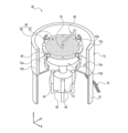
位置合わせ機構12の後方の領域には、例えば、樹脂を含む保護膜を被加工物11に形成する際に用いられる保護膜形成装置(洗浄装置)46が配置されている。図2は、保護膜形成装置46の斜視図であり、図3は、保護膜形成装置46の断面図である。なお、図2及び図3では、説明の便宜上、保護膜形成装置46の一部の要素が省略されている。
In the area behind the
図2及び図3に示されるように、保護膜形成装置46は、被加工物11をフレーム15とともに保持できる保持テーブル(スピンナーテーブル)48を備えている。保持テーブル48は、例えば、セラミックスや金属等で構成される円盤状の枠体50を含む。図3に示されるように、枠体50の上面側には、上端が円形状に開口した凹部50aが形成されている。枠体50の凹部50aには、この凹部50aの形状に合致する円盤状の保持板52が固定されている。
As shown in Figures 2 and 3, the protective
保持板52は、例えば、セラミックス等の材料で多孔質状に構成されており、その上面(保持面)52aによりテープ13を介して被加工物11の第2面11b側を保持する。なお、保持板52の上面52aは、保持板52が凹部50aに固定された状態で、X軸及びY軸に対して概ね平行になるように構成されている。
The holding
枠体50の内部には、凹部50aの底に一端が開口した流路50bが設けられている。一方で、流路50bの他端には、バルブ(不図示)等を介してエジェクタ等の吸引源(不図示)が接続されている。よって、バルブを開けば、吸引源で発生する負圧は、流路50bや凹部50a等を通じて保持板52の上面52aに作用する。
Inside the
例えば、保持テーブル48に被加工物11を載せ、第2面11b側に貼付されたテープ13が保持板52の上面52aに接触した状態で、この上面52aに吸引源の負圧を作用させると、テープ13は、保持板52の上面52aにより吸引される。つまり、テープ13が貼付された被加工物11は、第1面11a側が上方に露出した状態で保持テーブル48に保持される。
For example, when the
図2に示されるように、保持テーブル48の枠体50の下部には、円柱状のスピンドル54を介して、モータ等の回転駆動源56が接続されている。よって、保持テーブル48は、この回転駆動源56が生じる動力により、Z軸に対して概ね平行なスピンドル54の軸心(回転軸)の周りに回転する。回転駆動源56の周囲には、複数(本実施形態では、3組)のエアアクチュエータ58が設けられている。各エアアクチュエータ58を動作させると、保持テーブル48は、回転駆動源56やスピンドル54等とともに昇降する。
As shown in FIG. 2, a
保持テーブル48の枠体50の周縁部には、この保持テーブル48を回転させる時に生じる遠心力を利用して、保持テーブル48に載せられたフレーム15を上方から押さえることができる4組の押さえ機構60が、保持テーブル48の周方向に沿って概ね等間隔に配置されている。図3に示されるように、各押さえ機構60は、枠体50の周縁部から外向きに突出する支持アーム62を備えている。
Four sets of holding
この支持アーム62の基端部(内側の端部)は、ねじ等(不図示)で枠体50の周縁部に固定されている。支持アーム62の先端部(外側の端部)には、例えば、保持板52の上面52aに対して概ね平行で、保持板52の中央部と支持アーム62の先端部とを結ぶ直線(つまり、保持板52の半径に沿う方向、図3の半径方向r)に対して概ね垂直な支持軸64が設けられている。そして、この支持軸64には、押さえ部材66が回転自在な態様で支持されている。
The base end (inner end) of the
押さえ部材66は、支持軸64に支持される支持部66aと、支持部66aの一方側に位置する鉤状の押さえ部66bと、支持部66aの他方側に位置する錘部66cと、を含む。錘部66cの重量は、例えば、押さえ部66bの重量に比べて大きくなっており、保持テーブル48を高速に回転させない状態(押さえ部材66に大きな遠心力が作用しない状態)では、押さえ部66bの先端が上方の退避位置に位置付けられる。
The pressing
フレーム15が載せられた状態で保持テーブル48を高速に回転させると、この回転に伴う大きな遠心力が押さえ部材66に加わる。上述のように、錘部66cの重量は、押さえ部66bの重量に比べて大きいので、保持テーブル48を高速に回転させると、この回転に伴う大きな遠心力の作用で、押さえ部材66は、錘部66cが外向きに移動するように支持軸64の周りに回転する。
When the holding table 48 is rotated at high speed with the
その結果、保持テーブル48に載せられたフレーム15に対して、押さえ部66bの先端部が上方から接触し、フレーム15が押さえ部材66により下向きに押さえられる。よって、保持テーブル48を高速に回転させる場合にも、この押さえ機構60により、フレーム15が適切に保持される。
As a result, the tip of the
図2に示されるように、保持テーブル48の傍には、流体供給ユニット(保護膜形成ユニット、洗浄ユニット)68を構成するノズル(樹脂供給ノズル、洗浄ノズル)70が配置されている。このノズル70は、保護膜の原料となる液状の樹脂を供給する液状樹脂供給源(不図示)と、モータ等の回転駆動源(不図示)と、に接続されている。よって、ノズル70は、回転駆動源の動力により保持テーブル48の上方で移動し、保持テーブル48に保持された被加工物11の第1面11aに液状の樹脂を供給することができる。
As shown in FIG. 2, a nozzle (resin supply nozzle, cleaning nozzle) 70 constituting a fluid supply unit (protective film forming unit, cleaning unit) 68 is disposed next to the holding table 48. This
また、このノズル70は、洗浄用の流体を供給する洗浄流体供給源(不図示)にも接続されている。よって、ノズル70は、回転駆動源の動力により保持テーブル48の上方で揺動しながら、保持テーブル48に保持されている被加工物11の第1面11aや、保持テーブル48(保持板52)の上面52a等に向けて洗浄用の流体を噴射することができる。
The
このように、本実施形態にかかる流体供給ユニット68は、被加工物11の第1面11aに液状の樹脂を塗布して保護膜を形成することができ、また、被加工物11の第1面11aや、保持テーブル48の上面52a等を洗浄することができる。
In this way, the
なお、液状の樹脂としては、例えば、株式会社ディスコ製のHogoMax(登録商標)のような、水で容易に洗い流される水溶性のものが使用される。また、この液状の樹脂には、蛍光材料や燐光材料が添加されていることが望ましい。洗浄用の流体としては、例えば、純水に代表される液体や、エア等の気体を液体に混合した混合流体(二流体)等が使用される。 The liquid resin used is, for example, a water-soluble resin that can be easily washed away with water, such as HogoMax (registered trademark) made by Disco Corporation. It is also preferable that a fluorescent material or a phosphorescent material is added to this liquid resin. The cleaning fluid used may be, for example, a liquid such as pure water, or a mixed fluid (two-fluid) in which a gas such as air is mixed with a liquid.
図2に示されるように、保持テーブル48と流体供給ユニット68とは、液受け容器72の内側の空間に収容されている。この液受け容器72は、円盤状の底壁72aと、底壁72aの外周縁に沿って設けられた円筒状の外周壁72bと、を含む。つまり、液受け容器72は、上端部に円形状の開口部72cを持つ有底円筒状に形成されている。
As shown in FIG. 2, the holding table 48 and the
円盤状の底壁72aの中央部には、スピンドル54を通す円形状の開口部が形成されており、この開口部を囲むように、外周壁72bよりも直径及び高さが小さい円筒状の内周壁72dが設けられている。そのため、例えば、ノズル70から噴射された流体中の液体は、被加工物11や保持テーブル48に衝突して周囲に飛散したとしても、円筒状の外周壁72bと円筒状の内周壁72dとで挟まれた底壁72a上の領域に溜まる。なお、保持テーブル48の下部には、スピンドル54を囲む円筒状のカバー74が設けられている。
A circular opening through which the
底壁72aの外周壁72bと内周壁72dとで挟まれた部分には、底壁72aを厚みの方向に貫通する排液口72eが設けられている。排液口72eには、ドレーンホース76が接続されており、液受け容器72に溜まった液体は、排液口72e及びドレーンホース76を通じて保護膜形成装置46の外部へと排出される。なお、液受け容器72の下部には、脚78が設けられており、液受け容器72の高さは、保持テーブル48の高さ等に合わせて調整されている。
A
図3に示されるように、保持テーブル48(上面52a)の上方の領域には、上面52aに向けて光を放射することができる光源80が配置されている。この光源80は、代表的には、紫外線LED(Light Emitting Diode)を含み、液状の樹脂を原料として被加工物11に形成される保護膜に吸収される波長の光(紫外線)を下向きに放射する。なお、光源80の種類や光源80から放射される光の波長は、必ずしもこれらに限定されない。
As shown in FIG. 3, a
光源80の傍には、上面52a側からの光を受けて画像を形成することができる撮像ユニット82が配置されている。この撮像ユニット82は、例えば、光源80から放射された光を吸収した保護膜が発する光(蛍光、燐光等)の波長に感度を持つ受光素子84を含んでいる。受光素子84は、代表的には、PD(Photodiode)等の光センサである。もちろん、受光素子84として、1次元イメージセンサや2次元イメージセンサ等が用いられてもよい。
An
光源80及び撮像ユニット82は、例えば、保持テーブル48の上方に配置されたボールねじ式の直動機構86によって支持されており、保持テーブル48の半径の方向(図3の半径方向r)に沿って移動することができる。この直動機構86による光源80及び撮像ユニット82の移動と、保持テーブル48の回転と、を制御することにより、光源80及び撮像ユニット82は、保持テーブル48の任意の位置の上方に位置付けられる。
The
そのため、例えば、保持テーブル48を回転させ、且つ、光源80及び撮像ユニット82を保持テーブル48の半径の方向(半径方向r)に沿って移動させながら、上面52a側から放射される光を撮像ユニット82の受光素子84で検出すれば、上面52a側から放射された光の強度分布が得られる。つまり、撮像ユニット82は、上面52aの上方から上面52aを撮像して画像(光の強度分布)を形成することができる。
Therefore, for example, by rotating the holding table 48 and moving the
図1に示されるように、位置合わせ機構12、搬送機構14、移動機構16、レーザー加工ユニット38、カメラ42、保護膜形成装置46等の要素は、コントローラ88に接続されている。コントローラ88は、代表的には、処理装置90と、記憶装置92と、を含むコンピュータにより構成され、被加工物11が適切に加工されるように、保護膜形成装置46を含むレーザー加工装置2の各要素の動作等を制御する。
As shown in FIG. 1, the
処理装置90は、代表的には、CPU(Central Processing Unit)であり、上述した要素を制御するために必要な種々の処理を行う。記憶装置92は、例えば、DRAM(Dynamic Random Access Memory)等の主記憶装置と、ハードディスクドライブやフラッシュメモリ等の補助記憶装置と、を含む。このコントローラ88の機能は、例えば、記憶装置92に記憶されているプログラム等のソフトウェアに従い処理装置90が動作することにより実現される。
The
図4は、上述した保護膜形成装置46で使用される判定方法、及びこの判定方法を含む保護膜形成方法のフローチャートである。例えば、搬送機構14によってカセット10から位置合わせ機構12のガイドレール12a、12bへと引き出された被加工物11は、レーザービームで加工される前に、保護膜形成装置46により、その第1面11a側に保護膜を形成される。
Figure 4 is a flowchart of the determination method used by the protective
図5は、保護膜形成装置46の保持テーブル48の上面52aが露出した様子を示す断面図である。図5に示されるように、保持テーブル48の上面52aには、様々な理由で保護膜と同様の樹脂を含む樹脂片21が付着してしまうことがある。そこで、本実施形態にかかる判定方法及び保護膜形成方法では、保持テーブル48により被加工物11が保持される前に、保持テーブル48の上面52aに樹脂片21が付着しているか否かが判定される。
Figure 5 is a cross-sectional view showing the exposed
なお、この判定方法及び保護膜形成方法の各ステップは、プログラム等のソフトウェアに従ってコントローラ88により遂行される。まず、保持テーブル48の上面52aが被加工物11を保持していない状態で、上面52aの上方に配置されている光源80から上面52aへと向けて光が放射される(ステップST1)。図6は、光源80から保持テーブル48の上面52aに向けて光23が放射される様子を示す断面図である。
Each step of the determination method and protective film forming method is performed by the
具体的には、コントローラ88が、上述した液状の樹脂を原料とする保護膜に吸収される波長の光23を光源80に放射させる。この際に、コントローラ88は、回転駆動源56により保持テーブル48を回転させながら、直動機構86により光源80及び撮像ユニット82を移動させる。つまり、光源80は、保持テーブル48の上面52aに対して渦を描くように撮像ユニット82とともに相対的に移動しながら、上面52aに光23を照射する。
Specifically, the
保持テーブル48の回転数(回転速度)は、例えば、100rpm~1000rpm、代表的には、500rpmであり、光源80及び撮像ユニット82の移動速度は、例えば、1.0mm/s~10mm/s、代表的には、5.3mm/sである。ただし、保持テーブル48の回転数や光源80及び撮像ユニット82の移動速度は、これらの値に限定されない。
The number of rotations (rotational speed) of the holding table 48 is, for example, 100 rpm to 1000 rpm, typically 500 rpm, and the movement speed of the
上述のような光23が光源80から放射されている状態で、上面52a側から上向きに放射される光が撮像ユニット82の受光素子84により検出される。図7は、保持テーブル48の上面52aに付着している樹脂片21から発せられる光25が撮像ユニット82により検出される様子を示す断面図である。上述のように、受光素子84は、光源80から放射された光23を吸収した保護膜(保護膜と同様の樹脂を含む樹脂片21を含む)が発する光(蛍光、燐光等)の波長に感度を持つように構成されている。
When the light 23 as described above is emitted from the
また、撮像ユニット82は、上述のように、保持テーブル48の上面52aに対して渦を描くように光源80とともに相対的に移動している。そのため、この撮像ユニット82により、上面52a側から上方へと向けて放射される光の2次元的な強度分布(つまり、画像)が得られる。言い換えれば、撮像ユニット82により、保持テーブル48の上面52aが撮像される。
As described above, the
なお、本実施形態では、上面52aで反射した光23が受光素子84へと入射し難くなるように、上面52aに対する光23の入射角等が調整されている。より好ましくは、受光素子84は、光源80から放射され上面52aで反射する光23の波長に比べて、光23を吸収した保護膜が発する光の波長に対して高い感度を持つように構成されている。従って、この撮像ユニット82により、特に、上面52aに付着している樹脂片21から発せられる光25の2次元的な強度分布(つまり、画像)が得られる。
In this embodiment, the angle of incidence of light 23 with respect to
このように、コントローラ88は、光源80が光23を放射している状態で、被加工物11を保持していない状態の保持テーブル48の上面52aを撮像ユニット82に撮像させて、保持テーブル48の上面52aが写った画像を取得する(ステップST2)。図8は、保持テーブル48の上面52aが写った画像31の例を示す図である。
In this manner, the
図8に示されるように、画像31内の保持テーブル48の輪郭31aよりも内側の領域には、樹脂片21から発せられる光25を撮像ユニット82が検出した高輝度領域31bが存在する。高輝度領域31bを除く領域は、高輝度領域31bに比べて輝度が低い低輝度領域31cである。コントローラ88は、この画像31に基づき、保持テーブル48の上面52aに樹脂片21が付着しているか否かを判定する(ステップST3)。
As shown in FIG. 8, in the area inside the
例えば、所定のしきい値よりも輝度が高い高輝度領域31bが画像31内の輪郭31aよりも内側の領域に存在する場合に、コントローラ88は、保持テーブル48の上面52aに樹脂片21が付着していると判定する。一方で、このしきい値よりも輝度が高い高輝度領域31bが画像31内の輪郭31aよりも内側の領域に存在しない場合に、コントローラ88は、保持テーブル48の上面52aに樹脂片21が付着していないと判定する。
For example, if a high-
保持テーブル48の上面52aに樹脂片21が付着していると判定された場合には(ステップST3でYES)、保持テーブル48の上面52aが流体供給ユニット68により洗浄される(ステップST4)。図9は、保持テーブル48の上面52aが洗浄され、樹脂片21が除去された様子を示す断面図である。
If it is determined that
保持テーブル48の上面52aを洗浄する際には、図9に示されるように、コントローラ88は、保持テーブル48を回転させ、且つ、ノズル70を揺動させながら、このノズル70に洗浄用の流体27を噴射させる。これにより、保持テーブル48の上面52aが流体27で洗浄され、樹脂片21は、保持テーブル48の上面52aから除去される。
When cleaning the
保持テーブル48の上面52aが洗浄された後には、又は、保持テーブル48の上面52aに樹脂片21が付着していないと判定された場合には(ステップST3でNO)、被加工物11の第1面11a側に保護膜が形成される。図10は、被加工物11に保護膜が形成される様子を示す断面図である。
After the
具体的には、まず、コントローラ88は、搬送機構14により、テープ13を介してフレーム15に支持されている状態の被加工物11を、第1面11a側が上方に露出するように保持テーブル48の上面52aに載せる。すなわち、コントローラ88は、搬送機構14により、被加工物11の第2面11b側に貼付されているテープ13を保持テーブル48の上面52aに接触させる。
Specifically, first, the
次に、コントローラ88は、バルブを開き、吸引源で発生する負圧を保持板52の上面52aに作用させる。これにより、被加工物11の第2面11b側に貼付されているテープ13は、保持テーブル48の上面52aに吸引される。すなわち、第2面11b側にテープ13が貼付された被加工物11は、第1面11a側が上方に露出した状態で保持テーブル48に保持される(ステップST5)。
Next, the
その後、図10に示されるように、コントローラ88は、ノズル70を被加工物11の上方に移動させるとともに、このノズル70に液状の樹脂29を滴下させた上で、回転駆動源56により保持テーブル48を高速に回転させる。これにより、被加工物11の第1面11aには、保護膜の原料となる液状の樹脂29が塗布される(ステップST6)。被加工物11の第1面11aに塗布された液状の樹脂29を乾燥させることで、この第1面11aを覆う保護膜が完成する。
Then, as shown in FIG. 10, the
以上のように、本実施形態にかかる保護膜形成装置46は、保持テーブル48の上面(保持面)52aが被加工物11を保持していない状態で、上面52aの上方の光源80から上面52aへと向けて光を放射し、次に、被加工物11を保持していない状態の上面52aを撮像ユニット82に撮像させて上面52aが写った画像31を取得し、その後、画像31に基づいて上面52aに樹脂片21が付着しているか否かを判定するので、保持テーブル48の上面52aに樹脂片21が付着しているか否かを適切に判定できる。
As described above, the protective
なお、本発明は、上述した実施形態の記載に制限されず種々変更して実施可能である。例えば、上述した実施形態の保護膜形成装置46は、保護膜形成ユニットと洗浄ユニットとの双方の機能を併せ持つ流体供給ユニット68を備えているが、本発明にかかる保護膜形成装置は、保護膜形成ユニットと、保護膜形成ユニットとは別の洗浄ユニットと、を備えてもよい。なお、この場合には、保護膜形成ユニットが樹脂供給ノズルを有し、洗浄ユニットが洗浄ノズルを有する。
The present invention is not limited to the above-described embodiment, and can be modified in various ways. For example, the protective
また、上述した実施形態では、光源80及び撮像ユニット82を含む保護膜形成装置46の動作を制御するために、レーザー加工装置2の動作を制御するためのコントローラ88が使用されているが、保護膜形成装置46は、レーザー加工装置2から独立したコントローラを備えてもよい。
In addition, in the above-described embodiment, a
また、上述した実施形態では、保護膜(樹脂片21)が発する蛍光、燐光等の光を利用して、保持テーブル48の上面52aへの樹脂片21の付着の有無が判定されているが、他の原理に基づき保持テーブル48の上面52aへの樹脂片21の付着の有無が判定されてもよい。例えば、保持テーブル48の上面52aと樹脂片21との光学特性(反射率、吸光度等)の違いを利用して、保持テーブル48の上面52aへの樹脂片21の付着の有無を判定することができる。
In addition, in the above-described embodiment, the presence or absence of the
その他、上述の実施形態及び変形例にかかる構造、方法等は、本発明の目的の範囲を逸脱しない限りにおいて適宜変更して実施できる。 In addition, the structures, methods, etc. of the above-mentioned embodiments and modified examples can be modified as appropriate without departing from the scope of the purpose of the present invention.
2 :レーザー加工装置
4 :基台
4a :収容部
6 :支持構造
6a :支持アーム
8 :カセット支持台
10 :カセット
12 :位置合わせ機構
12a :ガイドレール
12b :ガイドレール
14 :搬送機構
16 :移動機構(加工送り機構、割り出し送り機構)
18 :Y軸ガイドレール
20 :Y軸移動テーブル
22 :Y軸ボールねじ
24 :Y軸パルスモータ
26 :X軸ガイドレール
28 :X軸移動テーブル
30 :X軸ボールねじ
32 :θテーブル
34 :チャックテーブル
34a :上面(保持面)
36 :クランプ
38 :レーザー加工ユニット
40 :加工ヘッド
42 :カメラ
46 :保護膜形成装置(洗浄装置)
48 :保持テーブル(スピンナーテーブル)
50 :枠体
50a :凹部
50b :流路
52 :保持板
52a :上面(保持面)
54 :スピンドル
56 :回転駆動源
58 :エアアクチュエータ
60 :押さえ機構
62 :支持アーム
64 :支持軸
66 :押さえ部材
66a :支持部
66b :押さえ部
66c :錘部
68 :流体供給ユニット(保護膜形成ユニット、洗浄ユニット)
70 :ノズル(樹脂供給ノズル、洗浄ノズル)
72 :液受け容器
72a :底壁
72b :外周壁
72c :開口部
72d :内周壁
72e :排液口
74 :カバー
76 :ドレーンホース
78 :脚
80 :光源
82 :撮像ユニット
84 :受光素子
86 :直動機構
88 :コントローラ
90 :処理装置
92 :記憶装置
11 :被加工物
11a :第1面
11b :第2面
13 :テープ(ダイシングテープ)
15 :フレーム
21 :樹脂片
23 :光
25 :光
27 :流体
29 :樹脂
31 :画像
31a :輪郭
31b :高輝度領域
31c :低輝度領域
2: Laser processing device 4:
18: Y-axis guide rail 20: Y-axis moving table 22: Y-axis ball screw 24: Y-axis pulse motor 26: X-axis guide rail 28: X-axis moving table 30: X-axis ball screw 32: θ table 34: Chuck table 34a: Upper surface (holding surface)
36: Clamp 38: Laser processing unit 40: Processing head 42: Camera 46: Protective film forming device (cleaning device)
48: Holding table (spinner table)
50:
54: Spindle 56: Rotation drive source 58: Air actuator 60: Pressing mechanism 62: Support arm 64: Support shaft 66: Pressing
70: Nozzle (resin supply nozzle, cleaning nozzle)
72:
15: Frame 21: Resin piece 23: Light 25: Light 27: Fluid 29: Resin 31:
Claims (7)
該被加工物の該第2面を保持する保持面を有し、回転駆動源に接続された保持テーブルと、
該保護膜の原料となる液状の樹脂を供給する樹脂供給ノズルを有し、該保持テーブルの該保持面により保持された該被加工物の該第1面に該液状の樹脂を塗布して該保護膜を形成する保護膜形成ユニットと、
該保持テーブルの該保持面の上方から該保持面へと向けて光を放射する光源と、
受光素子を有し、該保持テーブルの該保持面の上方から該保持テーブルの該保持面側を撮像して画像を形成する撮像ユニットと、
洗浄用の流体を供給する洗浄ノズルを有し、該保持テーブルの該保持面を洗浄する洗浄ユニットと、
処理装置と記憶装置とを有し、該記憶装置に記憶されているプログラムに従い該処理装置が動作することにより該光源及び該撮像ユニットの動作を制御するコントローラと、
を含み、
該コントローラは、該プログラムに従い、
該保持テーブルの該保持面が該被加工物を保持していない状態で、該光源に該光を放射させ、
該光源が該光を放射している状態で、該被加工物を保持していない状態の該保持面を該撮像ユニットに撮像させて該保持面が写った画像を取得し、
該画像に基づいて該保持面に該樹脂を含む樹脂片が付着しているか否かを判定する保護膜形成装置。 A protective film forming apparatus for forming a protective film including a resin on a first surface of a workpiece having a first surface and a second surface opposite to the first surface,
a holding table having a holding surface for holding the second surface of the workpiece and connected to a rotary drive source;
a protective film forming unit having a resin supply nozzle for supplying a liquid resin that is a raw material of the protective film, and applying the liquid resin to the first surface of the workpiece held by the holding surface of the holding table to form the protective film;
a light source that emits light from above the holding surface of the holding table toward the holding surface;
an imaging unit having a light receiving element and configured to image the holding surface side of the holding table from above the holding surface of the holding table to form an image;
a cleaning unit having a cleaning nozzle for supplying a cleaning fluid and cleaning the holding surface of the holding table;
a controller having a processing device and a storage device, the processing device operating in accordance with a program stored in the storage device to control operations of the light source and the imaging unit;
Including,
The controller, according to the program,
causing the light source to emit the light while the holding surface of the holding table is not holding the workpiece;
While the light source is emitting the light, the holding surface is imaged by the imaging unit in a state where the workpiece is not being held, thereby obtaining an image of the holding surface;
The protective film forming apparatus determines whether or not resin pieces containing the resin are attached to the holding surface based on the image.
該撮像ユニットの該受光素子は、該光を吸収した該保護膜が発する光の波長に感度を持つ請求項1に記載の保護膜形成装置。 the light source emits light at a wavelength that is absorbed by the protective film;
2. The protective film forming apparatus according to claim 1, wherein the light receiving element of the imaging unit has sensitivity to a wavelength of light emitted by the protective film after absorbing the light.
該コントローラは、該プログラムに従い、該洗浄ユニットに該保持面を洗浄させる請求項1又は請求項2に記載の保護膜形成装置。 If it is determined that the resin piece is attached to the holding surface,
3. The protective film forming apparatus according to claim 1, wherein the controller causes the cleaning unit to clean the support surface in accordance with the program.
該保持テーブルの該保持面が該被加工物を保持していない状態で、該保持面の上方の光源から該保持面へと向けて光を放射し、
該光源が該光を放射している状態で、該被加工物を保持していない状態の該保持面を撮像ユニットで撮像して該保持面が写った画像を取得し、
該画像に基づき該保持面に該樹脂片が付着しているか否かを判定する判定方法。 A method for determining whether or not a resin piece, which contains a resin contained in a protective film of a workpiece, is attached to a holding surface of a holding table having a holding surface for holding the workpiece, the method comprising:
emitting light from a light source above the holding surface toward the holding surface while the holding surface of the holding table is not holding the workpiece;
With the light source emitting the light, an image of the holding surface in a state where the workpiece is not being held is captured by an imaging unit to obtain an image of the holding surface;
A method for determining whether or not the resin pieces are attached to the holding surface based on the image.
該撮像ユニットは、該光を吸収した該保護膜が発する光の波長に感度を持つ受光素子を有する請求項4に記載の判定方法。 the light source emits light at a wavelength that is absorbed by the protective film;
5. The method according to claim 4, wherein the imaging unit has a light receiving element having sensitivity to the wavelength of light emitted by the protective film that has absorbed the light.
洗浄ユニットにより該保持面を洗浄する請求項4又は請求項5に記載の判定方法。 If it is determined that the resin piece is attached to the holding surface,
The method according to claim 4 or 5, further comprising cleaning the holding surface with a cleaning unit.
該保持面に該樹脂片が付着していると判定された場合であって該洗浄ユニットにより該保持面が洗浄された後に、又は、該保持面に該樹脂片が付着していないと判定された場合に、第1面と、該第1面とは反対側の第2面と、を有する該被加工物の該第2面を該保持テーブルの該保持面により保持し、
該保持テーブルの該保持面により保持された該被加工物の該第1面に該保護膜の原料となる液状の樹脂を塗布して該保護膜を形成する保護膜形成方法。 A protective film forming method including the determination method according to claim 6,
when it is determined that the resin pieces are attached to the holding surface and after the holding surface is cleaned by the cleaning unit, or when it is determined that the resin pieces are not attached to the holding surface, the second surface of the workpiece, which has a first surface and a second surface opposite to the first surface, is held by the holding surface of the holding table;
A protective film forming method for forming a protective film by applying a liquid resin, which is a raw material of the protective film, to the first surface of the workpiece held by the holding surface of the holding table.
Priority Applications (1)
| Application Number | Priority Date | Filing Date | Title |
|---|---|---|---|
| JP2023006279A JP2024102422A (en) | 2023-01-19 | 2023-01-19 | Protective film forming apparatus, judgment method, and protective film forming method |
Applications Claiming Priority (1)
| Application Number | Priority Date | Filing Date | Title |
|---|---|---|---|
| JP2023006279A JP2024102422A (en) | 2023-01-19 | 2023-01-19 | Protective film forming apparatus, judgment method, and protective film forming method |
Publications (1)
| Publication Number | Publication Date |
|---|---|
| JP2024102422A true JP2024102422A (en) | 2024-07-31 |
Family
ID=91968621
Family Applications (1)
| Application Number | Title | Priority Date | Filing Date |
|---|---|---|---|
| JP2023006279A Pending JP2024102422A (en) | 2023-01-19 | 2023-01-19 | Protective film forming apparatus, judgment method, and protective film forming method |
Country Status (1)
| Country | Link |
|---|---|
| JP (1) | JP2024102422A (en) |
-
2023
- 2023-01-19 JP JP2023006279A patent/JP2024102422A/en active Pending
Similar Documents
| Publication | Publication Date | Title |
|---|---|---|
| JP5133855B2 (en) | Protective film coating method | |
| US10946419B2 (en) | Foreign substance removal apparatus and foreign substance detection apparatus | |
| KR101584821B1 (en) | Protection film coating method and protection film coating device | |
| JP6765949B2 (en) | Wafer processing method | |
| KR20180087163A (en) | Laser machining apparatus | |
| CN108406105A (en) | Laser processing device | |
| JP7701189B2 (en) | How to measure the thickness of protective film | |
| JP4777783B2 (en) | Laser processing equipment | |
| JP6328522B2 (en) | Protective film coating method and protective film coating apparatus | |
| JP5065722B2 (en) | Laser processing equipment | |
| JP2024006412A (en) | Processing method and processing equipment | |
| JP6132696B2 (en) | Chuck table | |
| JP5715370B2 (en) | Detection method | |
| JP2024102422A (en) | Protective film forming apparatus, judgment method, and protective film forming method | |
| JP2008006379A (en) | Protective coating method | |
| KR20090067033A (en) | Protective coating device and laser processing machine | |
| JP4666583B2 (en) | Protective coating method | |
| CN116475863A (en) | Grinding device | |
| JP2013021211A (en) | Method for processing wafer | |
| JP7835627B2 (en) | Grinding device | |
| JP5788716B2 (en) | Dust discharge device | |
| JP2025129875A (en) | Laser processing device and laser processing method | |
| JP2014217805A (en) | Liquid resin coating device | |
| JP2021150494A (en) | Wafer processing method | |
| JP2016195218A (en) | Laser processing method |
Legal Events
| Date | Code | Title | Description |
|---|---|---|---|
| A621 | Written request for application examination |
Free format text: JAPANESE INTERMEDIATE CODE: A621 Effective date: 20251120 |