JP2024091500A - Electrosurgical Generators - Google Patents
Electrosurgical Generators Download PDFInfo
- Publication number
- JP2024091500A JP2024091500A JP2023207824A JP2023207824A JP2024091500A JP 2024091500 A JP2024091500 A JP 2024091500A JP 2023207824 A JP2023207824 A JP 2023207824A JP 2023207824 A JP2023207824 A JP 2023207824A JP 2024091500 A JP2024091500 A JP 2024091500A
- Authority
- JP
- Japan
- Prior art keywords
- module
- energy
- electrosurgical generator
- sub
- base module
- Prior art date
- Legal status (The legal status is an assumption and is not a legal conclusion. Google has not performed a legal analysis and makes no representation as to the accuracy of the status listed.)
- Pending
Links
Images


Classifications
-
- A—HUMAN NECESSITIES
- A61—MEDICAL OR VETERINARY SCIENCE; HYGIENE
- A61B—DIAGNOSIS; SURGERY; IDENTIFICATION
- A61B18/00—Surgical instruments, devices or methods for transferring non-mechanical forms of energy to or from the body
- A61B18/04—Surgical instruments, devices or methods for transferring non-mechanical forms of energy to or from the body by heating
- A61B18/12—Surgical instruments, devices or methods for transferring non-mechanical forms of energy to or from the body by heating by passing a current through the tissue to be heated, e.g. high-frequency current
- A61B18/1206—Generators therefor
- A61B18/1233—Generators therefor with circuits for assuring patient safety
-
- A—HUMAN NECESSITIES
- A61—MEDICAL OR VETERINARY SCIENCE; HYGIENE
- A61B—DIAGNOSIS; SURGERY; IDENTIFICATION
- A61B18/00—Surgical instruments, devices or methods for transferring non-mechanical forms of energy to or from the body
- A61B2018/00053—Mechanical features of the instrument of device
- A61B2018/00172—Connectors and adapters therefor
- A61B2018/00178—Electrical connectors
-
- A—HUMAN NECESSITIES
- A61—MEDICAL OR VETERINARY SCIENCE; HYGIENE
- A61B—DIAGNOSIS; SURGERY; IDENTIFICATION
- A61B18/00—Surgical instruments, devices or methods for transferring non-mechanical forms of energy to or from the body
- A61B18/04—Surgical instruments, devices or methods for transferring non-mechanical forms of energy to or from the body by heating
- A61B18/12—Surgical instruments, devices or methods for transferring non-mechanical forms of energy to or from the body by heating by passing a current through the tissue to be heated, e.g. high-frequency current
- A61B18/1206—Generators therefor
- A61B2018/124—Generators therefor switching the output to different electrodes, e.g. sequentially
-
- A—HUMAN NECESSITIES
- A61—MEDICAL OR VETERINARY SCIENCE; HYGIENE
- A61B—DIAGNOSIS; SURGERY; IDENTIFICATION
- A61B18/00—Surgical instruments, devices or methods for transferring non-mechanical forms of energy to or from the body
- A61B18/04—Surgical instruments, devices or methods for transferring non-mechanical forms of energy to or from the body by heating
- A61B18/12—Surgical instruments, devices or methods for transferring non-mechanical forms of energy to or from the body by heating by passing a current through the tissue to be heated, e.g. high-frequency current
- A61B18/1206—Generators therefor
- A61B2018/1246—Generators therefor characterised by the output polarity
-
- A—HUMAN NECESSITIES
- A61—MEDICAL OR VETERINARY SCIENCE; HYGIENE
- A61B—DIAGNOSIS; SURGERY; IDENTIFICATION
- A61B18/00—Surgical instruments, devices or methods for transferring non-mechanical forms of energy to or from the body
- A61B18/04—Surgical instruments, devices or methods for transferring non-mechanical forms of energy to or from the body by heating
- A61B18/12—Surgical instruments, devices or methods for transferring non-mechanical forms of energy to or from the body by heating by passing a current through the tissue to be heated, e.g. high-frequency current
- A61B18/1206—Generators therefor
- A61B2018/1273—Generators therefor including multiple generators in one device
Landscapes
- Health & Medical Sciences (AREA)
- Surgery (AREA)
- Engineering & Computer Science (AREA)
- Life Sciences & Earth Sciences (AREA)
- Biomedical Technology (AREA)
- Otolaryngology (AREA)
- Nuclear Medicine, Radiotherapy & Molecular Imaging (AREA)
- Plasma & Fusion (AREA)
- Physics & Mathematics (AREA)
- Heart & Thoracic Surgery (AREA)
- Medical Informatics (AREA)
- Molecular Biology (AREA)
- Animal Behavior & Ethology (AREA)
- General Health & Medical Sciences (AREA)
- Public Health (AREA)
- Veterinary Medicine (AREA)
- Surgical Instruments (AREA)
Abstract

【課題】異なるタイプの電気外科用ジェネレータの製造を容易に行うこと。
【解決手段】電気外科用ジェネレータ1は、電気外科用器具19の接続のために構成された少なくとも1つの出力ソケット17に少なくとも2つの電極ラインを介してHFエネルギーを供給する高電圧接続部を備える。高電圧接続部は、分配ユニットと、少なくとも1つの接続ポートが設けられたベースモジュール2とを備える。分配ユニットは、HFエネルギー分配ライン4と、データ信号のためのデータ通信分配配線5と、を備え、インバータユニット27から供給されたHFエネルギー並びにデータ信号を少なくとも1つの接続ポートに分配するように構成される。少なくとも1つの接続ポートは、サブモジュール7にHFエネルギー及びデータ信号を伝達するように構成される。
【選択図】図2A
An electrosurgical generator is provided that is adapted to facilitate the manufacture of different types of electrosurgical generators.
The electrosurgical generator (1) comprises a high voltage connection for supplying HF energy via at least two electrode lines to at least one output socket (17) configured for connection of an electrosurgical instrument (19). The high voltage connection comprises a distribution unit and a base module (2) provided with at least one connection port. The distribution unit comprises an HF energy distribution line (4) and a data communication distribution wiring (5) for data signals and is configured to distribute the HF energy supplied from an inverter unit (27) as well as the data signal to the at least one connection port. The at least one connection port is configured to transmit the HF energy and the data signal to a sub-module (7).
[Selected Figure] Figure 2A
Description
本発明は、電気外科用器具に高周波交流電圧を出力するように構成された電気外科用ジェネレータに関する。電気外科用ジェネレータは、ケーシングと、電源ユニットと、電気外科用器具の接続のために構成された少なくとも1つの出力ソケットに供給される高周波交流電圧を生成する高電圧用インバータユニットとを備える。 The present invention relates to an electrosurgical generator configured to output a high frequency alternating voltage to an electrosurgical instrument. The electrosurgical generator comprises a casing, a power supply unit, and a high voltage inverter unit that generates a high frequency alternating voltage that is supplied to at least one output socket configured for connection of an electrosurgical instrument.
電気外科手術又は高周波外科手術では、電気外科用メスなどの電気外科用器具を使用して、人体内の組織に高周波交流電流を印加している。通常、約200kHz~4,000kHzまでの無線周波数範囲内の高周波が使用されている。これにより、組織が局所的に加熱される。これにより、加熱により組織が切断又は切断によって分離され、熱切除により組織が除去される。これの主な利点は、影響を受けた血管を閉じることによって、切断と同時に出血を止めることができ、凝固などの他の用途に電気外科用器具を使用することができることである。電気外科用ジェネレータは、電気外科用器具に電力を供給するために利用され、高周波交流電圧を電気外科用器具に送達するように設計されているため、医療用のデバイスである。 Electrosurgery or radio frequency surgery uses electrosurgical instruments such as electrosurgical scalpels to apply high frequency alternating current to tissue within the human body. Typically, radio frequencies in the radio frequency range of about 200 kHz to 4,000 kHz are used. This causes the tissue to be locally heated. This causes the tissue to be cut or separated by cutting due to heating, and tissue to be removed by thermal ablation. The main advantage of this is that bleeding can be stopped at the same time as cutting by closing the affected blood vessels, and the electrosurgical instrument can be used for other applications such as coagulation. Electrosurgical generators are utilized to power electrosurgical instruments and are medical devices since they are designed to deliver high frequency alternating voltage to the electrosurgical instruments.
種々の医療分野のための電気外科用ジェネレータを提供するために、異なる構成要素を有し、異なる機能を特徴とする、異なるタイプの電気外科用ジェネレータが必要とされている。種々のタイプの電気外科用ジェネレータが存在しており、一般的な手術用のタイプとは別に、例えば、ほんの数例を挙げると、泌尿器科、婦人科、胃腸科、呼吸器科、ENT(耳鼻咽喉科)、瀉血、及び内臓手術に特化した種々のタイプが存在する。これらのタイプの各々の中には、電気外科用ジェネレータの異なる変形形態も存在し、あるものは、より小さい範囲の機能及び電力を有し、他のものは、より大きい範囲の機能及び電力を有している。これは、特定の手術作業のために正しい電気外科用ジェネレータを有することに関して外科医にとって有益である。他方、これは、膨大な数の異なる種類の電気外科用ジェネレータが存在することを意味する。 In order to provide electrosurgical generators for various medical fields, different types of electrosurgical generators are needed, having different components and featuring different functions. There are various types of electrosurgical generators, and apart from the types for general surgery, there are various types specialized for example, urology, gynecology, gastroenterology, pulmonology, ENT (ear, nose and throat), phlebotomy, and visceral surgery, to name just a few. Within each of these types, there are also different variants of electrosurgical generators, some with a smaller range of functions and power, others with a larger range of functions and power. This is beneficial for the surgeon in terms of having the right electrosurgical generator for a specific surgical task. On the other hand, this means that there is a huge number of different kinds of electrosurgical generators.
かかる非常に多様な電気外科用ジェネレータの開発及び製造は、製造業者にとって厄介である。更に、多種多様な電気外科用ジェネレータは、最新化をより複雑にし、技術革新の妨げとなっている。
そこで、電気外科用ジェネレータの異なるタイプの製造を容易に行うことができる技術が要望されている。
The development and manufacture of such a wide variety of electrosurgical generators is cumbersome for manufacturers. Furthermore, the wide variety of electrosurgical generators makes modernization more complicated and inhibits innovation.
Therefore, there is a need in the art for an easy way to manufacture different types of electrosurgical generators.
したがって、本発明の目的は、異なるタイプの製造を容易に行うことができる電気外科用ジェネレータを提供することである。 The object of the present invention is therefore to provide an electrosurgical generator that can be easily manufactured in different types.
本発明による解決策は、独立請求項の特徴による電気外科用ジェネレータにある。有利な発展形態は、従属請求項の主題である。 The solution according to the invention consists in an electrosurgical generator according to the features of the independent claims. Advantageous developments are the subject of the dependent claims.
電気外科用器具にHFエネルギーを出力するように構成された電気外科用ジェネレータでは、電気外科用器具に出力されるHFエネルギーを生成するインバータユニットと、電気外科用器具の接続のために構成された少なくとも1つの出力ソケットに少なくとも2つの電極ラインを介してHFエネルギーを供給する高電圧接続部と、を備え、高電圧接続部は、分配ユニットと、少なくとも1つの接続ポートが設けられたベースモジュールと、を備え、本発明によれば、分配ユニットは、HFエネルギー分配ラインと、データ信号のためのデータ通信分配配線と、を備え、インバータユニットから供給されたHFエネルギー並びにデータ信号を少なくとも1つの接続ポートに分配するように構成され、当該少なくとも1つの接続ポートは、サブモジュールに接続され、出力ソケットにHFエネルギーを供給する当該サブモジュールにHFエネルギー及びデータ信号を伝達するように構成される。 The electrosurgical generator configured to output HF energy to an electrosurgical instrument includes an inverter unit that generates the HF energy output to the electrosurgical instrument, and a high-voltage connection that supplies the HF energy via at least two electrode lines to at least one output socket configured for connection of the electrosurgical instrument, the high-voltage connection including a distribution unit and a base module provided with at least one connection port, and according to the present invention, the distribution unit includes an HF energy distribution line and a data communication distribution wiring for a data signal, and is configured to distribute the HF energy and the data signal supplied from the inverter unit to at least one connection port, and the at least one connection port is connected to a submodule and configured to transmit the HF energy and the data signal to the submodule that supplies the HF energy to the output socket.
以下では、本発明の文脈内で使用される一部の表現について説明する。 Below, we explain some expressions used within the context of the present invention.
インバータユニットは、出力ソケットに接続される手術器具に実際の高周波出力を提供するためのデバイスである。インバータという用語は、非常に広義であり、実際のインバータ技術、並びにコンバータ、例えばフォワードコンバータ若しくはフライバックコンバータ、又は増幅器を含む。 The inverter unit is a device for providing actual high frequency power to a surgical instrument connected to an output socket. The term inverter is very broad and includes actual inverter technology as well as converters, such as forward or flyback converters, or amplifiers.
本特許の文脈において、「HF」という用語は、「高周波」を意味し、電気外科用ジェネレータのインバータユニットによって生成される200kHz~4000kHzの無線周波数範囲内の周波数に関する。しかしながら、超音波器具を駆動することができる電気外科用ジェネレータについては、「高周波数」という用語は、典型的には20kHz~200kHz(超音波外科用ジェネレータ)の範囲内の超音波周波数範囲にも関する。HFエネルギーは、特に10kVまで、好ましくは4000ボルトまで、更に好ましくは100ボルトを超える高電圧範囲の振幅を有する場合、本特許の文脈において高電圧であると見なされる高周波交流電圧として出力され得る。 In the context of this patent, the term "HF" means "high frequency" and relates to frequencies in the radio frequency range of 200 kHz to 4000 kHz generated by an inverter unit of an electrosurgical generator. However, for electrosurgical generators capable of driving ultrasonic instruments, the term "high frequency" also relates to the ultrasonic frequency range, typically in the range of 20 kHz to 200 kHz (ultrasonic surgical generators). HF energy can be output as a high frequency alternating voltage, which is considered to be a high voltage in the context of this patent, especially when it has an amplitude in the high voltage range of up to 10 kV, preferably up to 4000 volts, and more preferably more than 100 volts.
「接続ポート」は、電気的接触が行われるように、サブモジュールをベースモジュール及びその分配ユニットに接続することができるデバイスである。接続ポートは、単一(例えば、ハイブリッドコネクタ)、対、又は複数のコネクタを介して、関連サブモジュールに接続されてもよい。 A "connection port" is a device that can connect a sub-module to a base module and its distribution unit so that electrical contact is made. A connection port may be connected to an associated sub-module via a single (e.g., hybrid connector), pair, or multiple connectors.
「ハイブリッドコネクタ」という用語は、HF電力及び信号を伝達するための異なるセクションを備えるコネクタとして理解されるべきである。ハイブリッドコネクタは、HF電力用のセクションと、信号用の別のセクションとを特徴とし、これらのセクションは、単一のコネクタに結合される。 The term "hybrid connector" should be understood as a connector with different sections for transmitting HF power and signals. A hybrid connector features a section for HF power and another section for signals, which are combined into a single connector.
本特許の文脈において、「サブモジュール」は、ベースモジュールに取り付けられ、インバータユニットによって生成された高周波交流電圧を出力ソケットに供給するように構成されたモジュールである。典型的には、サブモジュールはプリント回路基板を含む。出力ソケットは、サブモジュール上に直接配置されてもよく、又は接続部を介してサブモジュールに接続されてもよい。 In the context of this patent, a "submodule" is a module that is attached to a base module and configured to provide a high frequency AC voltage generated by an inverter unit to an output socket. Typically, a submodule includes a printed circuit board. The output socket may be located directly on the submodule or may be connected to the submodule via a connection.
本発明は、独立請求項に定義されるようなベースモジュールを提供することによって、ベースモジュールの1つ又は複数の接続ポートが、電気外科用ジェネレータの特定のタイプ又は変形形態のために選択されたサブモジュールの種々の構成に接続され得るという事実を利用する。それによって、手元にある特定のタイプ又は変形形態の必要性に合わせて電気外科用ジェネレータを形成することが非常に容易になる。それによって、所望の機能を達成するために、関連するサブモジュール(複数可)を適切な接続ポートに挿入すること以外の更なる修正なしに、種々のタイプ又は変形形態を製造することができる。これにより、電気的接続とデータ通信とが同時に確立される。その結果、1つ又は別の接続ポートに異なるサブモジュールを挿入することによって、電気外科用ジェネレータのタイプ及び変形形態のはるかに簡略化された変更が可能になる。これにより、電気外科用ジェネレータの多くの異なるタイプ及び変形形態の製造が、はるかに少ない労力で可能となる。 The present invention, by providing a base module as defined in the independent claims, takes advantage of the fact that one or more connection ports of the base module can be connected to various configurations of sub-modules selected for a particular type or variant of the electrosurgical generator. This makes it very easy to tailor the electrosurgical generator to the needs of the particular type or variant at hand. This allows various types or variants to be manufactured without further modification other than inserting the relevant sub-module(s) into the appropriate connection port to achieve the desired functionality. This simultaneously establishes electrical connection and data communication. As a result, a much simplified change of type and variant of the electrosurgical generator is possible by inserting different sub-modules into one or another connection port. This allows the manufacture of many different types and variants of electrosurgical generators with much less effort.
更に、最新化及び更新も容易になる。新しいバージョンのサブモジュールが開発された場合、ベースモジュールを変更する必要なく、接続ポートに挿入するだけでよい。ベースモジュールは、いかなる場合にもサブモジュールを適切に供給する。 In addition, modernization and updates are also made easier: if a new version of a sub-module is developed, it can simply be inserted into the connection port without the need to change the base module. The base module will supply the sub-module appropriately in any case.
好ましくは、少なくとも1つの接続ポートは、異なるタイプの、特に電極ラインの数及び/又は種類が異なるサブモジュールに接続可能であるようにユニバーサルコネクタとして構成される。これは、サブモジュールのいずれかを別のサブモジュール、特に、異なる機能を有し、かつ/又は高周波分配ユニットへの異なる接続を必要とする別のサブモジュールに変更することによって、電気外科用ジェネレータの既存のタイプ又は変形形態を容易に修正又は再構成することができるという利点をもたらす。好ましくは、異なるタイプのサブモジュールは、単極サブモジュール、双極サブモジュール、中性電極サブモジュール、及び/又は汎用サブモジュールを備える。それによって、単極及び双極のような異なる種類のサブモジュールを使用することができ、必要であれば、ベースモジュールを変更することなく交換することができることは、重要な利点である。接続ポートは、必要な電極及びデータシグナリングを提供し、それによって、異なるタイプのサブモジュールを採用することに関して最適な柔軟性が得られる。かかる異なるタイプのサブモジュールの顕著な例は、単極ソケットモジュール、双極ソケットモジュール、中性電極ソケットモジュール、及び/又は汎用ソケットモジュールである。これに限定されず、他のタイプの任意のサブモジュールが設けられてもよい。 Preferably, at least one connection port is configured as a universal connector so that it can be connected to sub-modules of different types, in particular different numbers and/or types of electrode lines. This provides the advantage that an existing type or variant of the electrosurgical generator can be easily modified or reconfigured by changing any of the sub-modules to another sub-module, in particular another sub-module having a different functionality and/or requiring a different connection to the radiofrequency distribution unit. Preferably, the different types of sub-modules comprise monopolar sub-modules, bipolar sub-modules, neutral electrode sub-modules, and/or universal sub-modules. Thereby, it is an important advantage that different kinds of sub-modules, such as monopolar and bipolar, can be used and, if necessary, exchanged without changing the base module. The connection port provides the necessary electrodes and data signaling, thereby providing optimal flexibility in terms of employing different types of sub-modules. Notable examples of such different types of sub-modules are monopolar socket modules, bipolar socket modules, neutral electrode socket modules, and/or universal socket modules. Without being limited thereto, any other type of sub-module may be provided.
有利には、分配ユニットは、HFエネルギー及びデータ信号を複数の接続ポートに分配する。本発明は、単一の接続ポートを有するだけで機能するが、複数の接続ポートが分配ユニットによって供給される場合、その有用性は増大する。これは、種々の接続ポートにおいて異なるサブモジュールを使用することによって、非常に多数の変形形態を作成する可能性を提供する。 Advantageously, the distribution unit distributes the HF energy and data signals to multiple connection ports. Although the invention works with only a single connection port, its usefulness increases if multiple connection ports are provided by the distribution unit. This offers the possibility to create a very large number of variations by using different sub-modules at the various connection ports.
好ましくは、少なくとも1つの接続ポートは、HFエネルギーのための第1のセクションと、データ信号のための第2のセクションとを備えるハイブリッドコネクタとして形成される。これは、両方を適切に供給するためのハイブリッドコネクタ接点を差し込むことによって、HFエネルギーとデータ通信のための信号が同時に確立されることを意味する。このセクションは、好ましくは絶縁材料で作られた壁及び/又は適切な絶縁のために十分な寸法の空間によって分離されてもよい。追加のセクション、例えば、絶縁又は間隔セクション及び/又は他のタイプの電気接点、例えば、低電圧電源のためのセクションが存在してもよい。 Preferably, at least one connection port is formed as a hybrid connector with a first section for HF energy and a second section for data signals. This means that HF energy and signals for data communication are established simultaneously by plugging the hybrid connector contacts for the appropriate supply of both. The sections may be separated by walls, preferably made of insulating material and/or by spaces of sufficient dimensions for proper insulation. Additional sections may be present, for example insulating or spacing sections and/or other types of electrical contacts, for example sections for low voltage power supplies.
有利には、HFエネルギー分配ラインは、アクティブ電極、中性電極、及び少なくとも1つの追加の電極、好ましくは第2のアクティブ電極のための高電圧導体を備える。電極のかかる組み合わせによって、種々の異なる種類のサブモジュール、特に単極ソケットモジュール及び双極ソケットモジュールにHF電圧を供給することができる。更に、追加の電極は、特別な電気外科用器具のための、又は第2の電気外科用器具に供給する追加のサブモジュールに電力を供給するための第2のアクティブ電極として使用され得る。好ましくは、追加の電極の導体は、第2のアクティブ電極として作用する、又は他の電極のうちの1つ、中性電極若しくはアクティブ電極と接続されるなど、種々の状態間で切り替え可能である。かかる切り替え可能な特性によって、追加の電極の汎用性が高められる。 Advantageously, the HF energy distribution line comprises high voltage conductors for an active electrode, a neutral electrode, and at least one additional electrode, preferably a second active electrode. Such a combination of electrodes allows the supply of HF voltage to various different types of sub-modules, in particular monopolar and bipolar socket modules. Furthermore, the additional electrode can be used as a second active electrode for a special electrosurgical instrument or to supply power to an additional sub-module that supplies a second electrosurgical instrument. Preferably, the conductor of the additional electrode is switchable between various states, such as acting as a second active electrode or being connected with one of the other electrodes, the neutral electrode or the active electrode. Such a switchable property increases the versatility of the additional electrode.
好ましい実施形態では、HFエネルギー分配ラインは、超音波周波数範囲の電圧(超音波周波数電圧)のための導体を更に備える。それによって、超音波器具のためのサブモジュール、又は超音波器具とHF器具との組み合わせ(例えば、Olympus SurgicalのThunderbeat)のためのサブモジュールを供給することが更に可能になる。これにより、超音波周波数電圧のための導体は、好ましくは追加の導体であるが、代替的に共有導体として構成されてもよい。「共有導体」とは、当該導体が切り替え可能な導体であること、すなわち、超音波導体であることと、別の電極用の導体、例えば、第2のアクティブ電極用の導体であることとの間で切り替え可能であることを意味する。それによって、例えば、超音波周波数電圧を必要とするサブモジュールが存在する場合、超音波のために、又は、例えば、第2の電気外科用器具が電力供給されるべきである場合、第2のアクティブ電極のために、追加の導体を使用するための高度な柔軟性が提供される。 In a preferred embodiment, the HF energy distribution line further comprises a conductor for a voltage in the ultrasonic frequency range (ultrasonic frequency voltage). This further makes it possible to supply a submodule for an ultrasonic instrument or a combination of an ultrasonic instrument and an HF instrument (e.g. Thunderbeat from Olympus Surgical). Thus, the conductor for the ultrasonic frequency voltage is preferably an additional conductor, but may alternatively be configured as a shared conductor. By "shared conductor" it is meant that the conductor is a switchable conductor, i.e. it can be switched between being an ultrasonic conductor and being a conductor for another electrode, e.g. a second active electrode. This provides a high degree of flexibility to use an additional conductor for ultrasonics, e.g. if a submodule requiring ultrasonic frequency voltage is present, or for a second active electrode, e.g. if a second electrosurgical instrument is to be powered.
ベースモジュールは、好ましくは、接続ポートを介してサブモジュールのための動作電力を伝達するように構成された器具電圧分配配線を更に備える。これにより、サブモジュールの内部回路のような器具に電力を供給するために必要な電力は、同じ接続ポートを使用して伝達され得る。これにより、基板上に多くの回路を有する電力供給された「スマート」サブモジュールであっても、電力供給を必要としない単なるパッシブモジュールと同様に、接続ポートを介して接続することができる。これは、これがハイブリッドコネクタの第3のセクションとして具現化される場合に、取り扱いを最も容易にするために特に有益である。 The base module preferably further comprises an appliance voltage distribution wiring configured to transmit operating power for the sub-modules via the connection port. This allows the power required to power the appliances, such as the internal circuitry of the sub-modules, to be transmitted using the same connection port. This allows even powered "smart" sub-modules, with lots of circuitry on board, to be connected via the connection port, just like a passive module that does not require power. This is particularly beneficial when this is embodied as the third section of a hybrid connector for maximum ease of handling.
好ましい実施形態では、ベースモジュールは回路基板であり、HFエネルギー分配ラインは高電圧バスバーとして構成される。ベースモジュールを回路基板として構成することによって、接続ポート、好ましくはハイブリッドコネクタのための適切な支持を提供することを可能にする固体の機械的ベースが形成される。それによって、サブモジュールを接続ポート、好ましくはハイブリッドコネクタに差し込むことが非常に容易になり、サブモジュールは、差し込まれた状態でも当該回路基板によって機械的に支持することができる。しかしながら、これは必須ではなく、ベースモジュールは、接続ポートを備え、HFエネルギー、データ通信、及び適用可能な場合には器具電圧を伝達するケーブルセットとして構成することもできる。 In a preferred embodiment, the base module is a circuit board and the HF energy distribution lines are configured as high voltage bus bars. By configuring the base module as a circuit board, a solid mechanical base is created that allows for providing adequate support for the connection port, preferably a hybrid connector. This makes it very easy to plug the sub-module into the connection port, preferably a hybrid connector, and the sub-module can be mechanically supported by the circuit board even in the plugged-in state. However, this is not required and the base module can also be configured as a cable set with connection ports and transmitting HF energy, data communication and, where applicable, the appliance voltage.
かかるバスバーによって、HFエネルギーを中央給電点から複数の接続ポートに効率的に分配することができる。更に、接続ポート、特にハイブリッドコネクタは、バスバーに沿った任意の点に位置することができ、これは、接続ポート、特にハイブリッドコネクタの位置決めの柔軟性を更に高める。 Such a busbar allows for efficient distribution of HF energy from a central feed point to multiple connection ports. Furthermore, the connection ports, particularly the hybrid connectors, can be located at any point along the busbar, which further increases the flexibility in positioning the connection ports, particularly the hybrid connectors.
有利には、高電圧バスバーは、それらの間に規定された間隔を有する複数の、好ましくは少なくとも3つの細長い導体によって形成される。これにより、導体の絶縁に必要とされる適切な間隔を確保することができ、これは、数百ボルト以上の範囲の高電圧がHFエネルギーに使用される場合に特に重要である。更に、かかる導体の構成により、導体の向きによって画定されるラインに沿ってサブモジュールを並べて配置することが可能になる。これにより、複数のサブモジュールを有する複雑な電気外科用ジェネレータの場合であっても、サブモジュールの良好な配置及び明確にレイアウトされた位置決めが得られる。好ましくは、高電圧バスバーは、回路基板上のレール又はストライプによって形成される。これにより、レール状の細長い導体を簡単かつ確実な方法で回路基板上に直接形成することができる。導体が回路基板、好ましくはベースモジュールの回路基板上にストライプとして形成される場合、導体の位置ずれ又は導体の相対間隔の望ましくない変動のいかなるリスクも効果的に排除される。 Advantageously, the high voltage busbar is formed by a plurality of, preferably at least three, elongated conductors with a defined spacing between them. This allows to ensure the appropriate spacing required for the insulation of the conductors, which is particularly important when high voltages in the range of several hundred volts and above are used for HF energy. Furthermore, such a conductor configuration allows the submodules to be arranged side by side along a line defined by the orientation of the conductors. This results in a good arrangement and clearly laid out positioning of the submodules even in the case of complex electrosurgical generators with several submodules. Preferably, the high voltage busbar is formed by rails or stripes on the circuit board. This allows rail-like elongated conductors to be formed directly on the circuit board in a simple and reliable manner. If the conductors are formed as stripes on the circuit board, preferably the circuit board of the base module, any risk of misalignment of the conductors or undesirable variations in the relative spacing of the conductors is effectively eliminated.
一実施形態では、出力ソケットは、サブモジュール上に直接配置することができる。これは、サブモジュールから出力ソケットへの短い供給経路を提供する。代替的な変形形態では、出力ソケットは、サブモジュールから取り外されてもよい。この変形形態では、サブモジュールは、相互接続ラインによって出力ソケットに接続される。かかる相互接続ラインは、出力ソケットの柔軟な位置決めを可能にし、例えば、ベースモジュール上に位置決めされたサブモジュールの実際の位置に関係なく、電気外科用ジェネレータのケーシング上のどこにでも位置することができる。相互接続ラインは、好ましくは、HFエネルギー及び信号リードを含む。好ましくはHFエネルギーリードと共通のケーブルに一体化されたかかる追加の信号リードを設けることによって、非常に複雑な電気外科用器具及びハンドスイッチを有するそれらの器具を出力ソケットに差し込むことができる。信号リードは、サブモジュールによってベースモジュールのデータ通信分配配線に接続されることが好ましい。 In one embodiment, the output socket can be located directly on the sub-module. This provides a short supply path from the sub-module to the output socket. In an alternative variation, the output socket can be detached from the sub-module. In this variation, the sub-module is connected to the output socket by an interconnection line. Such an interconnection line allows flexible positioning of the output socket, e.g., it can be located anywhere on the casing of the electrosurgical generator, regardless of the actual location of the sub-module positioned on the base module. The interconnection line preferably includes HF energy and signal leads. By providing such additional signal leads, preferably integrated in a common cable with the HF energy leads, very complex electrosurgical instruments and those instruments with hand switches can be plugged into the output socket. The signal leads are preferably connected by the sub-module to the data communication distribution wiring of the base module.
好ましくは、接続ポートのためにリレーが設けられ、リレーの各々は、接続ポートのうちの1つと相互作用し、接続ポートのうちの当該1つによって伝達されるHFエネルギーをオンに切り替えるか、又は遮断するように構成される。これにより、保護効果を達成することができる。特に、サブモジュールが接続ポートにおいてベースモジュールに適切に接続され、出力ソケットに差し込まれた器具が通電される場合、リレーはオンに切り替わり、それによって、HFエネルギーがベースモジュールの分配ユニットからサブモジュールを介して出力ソケットに差し込まれた器具に渡されることを可能にする。これにより、サブモジュールが接続ポート内に適切に装着されていない場合、又は器具がアクティブ化されていないために実際の要求がない場合、リレーはアクティブ化されず、HFエネルギーは器具に流れない。それによって、追加の安全機能を達成することができる。 Preferably, relays are provided for the connection ports, each of which is configured to interact with one of the connection ports and to switch on or cut off the HF energy transmitted by said one of the connection ports. This allows a protective effect to be achieved. In particular, when the sub-module is properly connected to the base module at the connection port and the appliance plugged into the output socket is energized, the relay switches on, thereby allowing the HF energy to be passed from the distribution unit of the base module through the sub-module to the appliance plugged into the output socket. Thus, when the sub-module is not properly seated in the connection port or there is no actual demand because the appliance is not activated, the relay is not activated and no HF energy flows to the appliance. This allows an additional safety function to be achieved.
有利には、接続ポートのうちの1つと相互作用するリレーは、サブモジュールが互換性チェックに合格した場合に発行される信号に応じてオンに切り替わるように構成される。これにより、正しいサブモジュールが取り付けられた場合にのみ、HFエネルギーがリレーによってスイッチオンされることを達成することができる。サブモジュールが正しくない場合、リレーはオンに切り替わらず、それによってHFエネルギーを遮断する。これは、デバイスの安全性を著しく向上させる。 Advantageously, the relay interacting with one of the connection ports is configured to switch on depending on a signal issued if the sub-module has passed the compatibility check. This makes it possible to achieve that the HF energy is switched on by the relay only if the correct sub-module is installed. If the sub-module is incorrect, the relay does not switch on, thereby interrupting the HF energy. This significantly improves the safety of the device.
リレーは、ベースモジュール上の接続ポート又は接続ポートの近傍に位置してもよい。しかしながら、好ましい実施形態では、リレーはサブモジュール上に位置し、好ましくは、リレーは、当該サブモジュールに接続された接続ポートのうちの当該1つによって伝達される個々のイネーブル信号によって通電される。したがって、リレーは、保護すべきサブモジュール上に配置され、したがって、それぞれのサブモジュールの要件に従って構成することができる。これは、ベースモジュール上に位置する場合に必要となる一種のユニバーサルリレーとは対照的に、異なるサブモジュールの種々の要件により良好に適したリレー構成を可能にする。 The relay may be located at or near a connection port on the base module. However, in a preferred embodiment, the relay is located on the submodule, and preferably the relay is energized by an individual enable signal transmitted by said one of the connection ports connected to said submodule. The relay is thus located on the submodule to be protected and can therefore be configured according to the requirements of the respective submodule. This allows a relay configuration that is better suited to the various requirements of the different submodules, as opposed to a kind of universal relay that would be necessary if it were located on the base module.
それ自体で独立した保護に値し得る好ましい実施形態では、少なくとも1つの追加の接続ポートと、拡張されたHFエネルギー分配ラインと、拡張されたデータ通信分配配線とを備える任意の拡張ボードが提供され、少なくとも1つの追加の接続ポートは、ベースモジュールの接続ポートのように、当該拡張されたHFエネルギー分配ライン及び拡張されたデータ通信分配配線に接続される。 In a preferred embodiment, which may merit independent protection in itself, an optional expansion board is provided with at least one additional connection port, an extended HF energy distribution line, and an extended data communication distribution wiring, and the at least one additional connection port is connected to the extended HF energy distribution line and the extended data communication distribution wiring as the connection port of the base module.
かかる拡張モジュールによって、追加の接続ポートを設けることができ、それによって、電気外科用ジェネレータが、拡張モジュール上に複数の追加のサブモジュールを提供することを可能にする。これは、非常に複雑な電気外科用ジェネレータのハードウェアの適応を可能にする一方で、依然として同じベースモジュールを採用し、単に当該拡張モジュールによってそれを強化する。電気外科用ジェネレータの「リーン」又は「リッチ」なモジュール及び出力ソケット構成のための異なる部品の使用を最小限に抑えることができる。 Such expansion modules can provide additional connection ports, thereby allowing the electrosurgical generator to provide multiple additional sub-modules on the expansion module. This allows for the adaptation of highly complex electrosurgical generator hardware while still employing the same base module and simply enhancing it with the expansion module. The use of different parts for "lean" or "rich" module and output socket configurations of the electrosurgical generator can be minimized.
好ましい実施形態では、ベースモジュールは、ベースモジュールのHFエネルギー分配ラインが拡張モジュールのHFエネルギー分配ラインに接続され、ベースモジュールのデータ分配配線及び/又は器具電圧分配配線が拡張モジュールのそれぞれの分配配線に接続されるように、拡張モジュールを取り付けるためのインターフェースを備える。インターフェースによって、拡張モジュールは、分配ユニットの拡張として機能するベースモジュールに接続される。これにより、拡張モジュール上に配置される追加のサブモジュールの供給が容易になり、電気外科用ジェネレータの機能を高めるための追加のサブモジュールを容易に取り付けることができる。 In a preferred embodiment, the base module includes an interface for mounting an expansion module such that the HF energy distribution lines of the base module are connected to the HF energy distribution lines of the expansion module and the data distribution wiring and/or the instrument voltage distribution wiring of the base module are connected to the respective distribution wiring of the expansion module. By means of the interface, the expansion module is connected to the base module which acts as an extension of the distribution unit. This facilitates the provision of additional sub-modules to be placed on the expansion module, and allows easy mounting of additional sub-modules to enhance the functionality of the electrosurgical generator.
有利には、拡張モジュールの分配ユニットは、別の電極のための補助導体を備える。これにより、拡張モジュール上に配置されたサブモジュールは、ベースモジュール上に配置されたサブモジュールとは異なるアクティブ電極を使用することができる。これは、増加した種類の異なるサブモジュールを可能にし、相互運用性の範囲を更に増加させる。例えば、ブリッジ構成で単極サブモジュールを使用することが可能であり、一方、正側のための1つのサブモジュールがベースモジュール上に配置され、負側のための相補的な単極サブモジュールが、好ましくは逆の、すなわち負の極性を有する別のアクティブ電極として追加の導体を採用するように構成された拡張モジュール上に配置される。これにより、ベースモジュール及び拡張モジュールを有するという本発明の概念に従いながら、電極の非常に高度な構成を達成することができる。 Advantageously, the distribution unit of the expansion module comprises an auxiliary conductor for another electrode. This allows the submodules arranged on the expansion module to use a different active electrode than the submodules arranged on the base module. This allows an increased variety of different submodules, further increasing the range of interoperability. For example, it is possible to use monopolar submodules in a bridge configuration, while one submodule for the positive side is arranged on the base module and a complementary monopolar submodule for the negative side is arranged on the expansion module, which is preferably configured to employ an additional conductor as another active electrode with the opposite, i.e. negative, polarity. This allows a very advanced configuration of electrodes to be achieved while following the inventive concept of having a base module and an expansion module.
好ましくは、インターフェースは、拡張モジュールの補助導体をベースモジュールの導体のうちの1つ、好ましくはベースモジュールの中性電極に絶縁又は接続するように構成された少なくとも1つのスイッチを備える。それによって、拡張モジュールの補助導体は、それ自体の独立した電位を有する追加の電極として、又は中性電極として選択的に使用することができる。後者の場合、単極ブリッジ構成の2つの単極サブモジュールを供給することができ、一方はベースモジュール上にあり、他方は拡張モジュール上にある。 Preferably, the interface comprises at least one switch configured to isolate or connect the auxiliary conductor of the expansion module to one of the conductors of the base module, preferably to the neutral electrode of the base module. Thereby, the auxiliary conductor of the expansion module can be selectively used as an additional electrode with its own independent potential or as a neutral electrode. In the latter case, two monopole submodules in a monopole bridge configuration can be supplied, one on the base module and the other on the expansion module.
有利には、インターフェースは、ベースモジュールの電極導体を拡張モジュールの電極導体に交差接続するように構成された少なくとも1つの切替えスイッチを更に備え、切替えスイッチは、好ましくは、拡張モジュールの少なくとも1つの追加の接続ポートに接続されたサブモジュールのタイプに応じて自動的に作動される。かかる交差接続によって、拡張モジュールは、そのサブモジュールに、アクティブ電極のためにベースモジュール上で使用される電位とは異なる電位を供給することが可能になる。これは、特に、電気外科用器具が二重双極方式で供給されることを可能にする。更に、インターフェース及びその導体の拡張モジュールへの接続は、拡張モジュールの接続ポートに実際に挿入されるサブモジュールの仕様に従って自動的に選択される。これは、適切な構成のために手動の相互作用を必要とすることなく、使用され得るサブモジュールのタイプに関して適応性及び柔軟性の範囲を増加させる。 Advantageously, the interface further comprises at least one changeover switch configured to cross-connect the electrode conductors of the base module to the electrode conductors of the expansion module, the changeover switch being preferably automatically activated depending on the type of sub-module connected to at least one additional connection port of the expansion module. Such a cross-connection allows the expansion module to supply its sub-modules with potentials different from those used on the base module for the active electrodes. This allows, in particular, electrosurgical instruments to be supplied in a dual bipolar manner. Furthermore, the connection of the interface and its conductors to the expansion module is automatically selected according to the specifications of the sub-module actually inserted in the connection port of the expansion module. This increases the range of adaptability and flexibility in terms of the types of sub-modules that can be used, without requiring manual interaction for proper configuration.
好ましくは、拡張モジュールは、独自のHFエネルギー入力端子を有し、ベースモジュールには、インターフェースを介してHFエネルギーが供給される。これは、拡張モジュールにHFエネルギーを直接供給することを可能にし、更に、インターフェースを介して拡張モジュールからベースモジュールに逆行供給することを可能にする。これは、高電圧の最適な供給のための短い距離を保証し、更に、拡張モジュール上に存在する追加の導体に必要なHFエネルギーを直接供給することができるという利点を有する。 Preferably, the expansion module has its own HF energy input terminal and the base module is supplied with HF energy via the interface. This allows for a direct supply of HF energy to the expansion module and also allows for a back-feed from the expansion module to the base module via the interface. This ensures short distances for an optimal supply of high voltage and has the further advantage that the required HF energy can be supplied directly to additional conductors present on the expansion module.
本発明は、有利な実施形態を示す添付の図面と併せて、例として以下により詳細に説明される。 The invention is explained in more detail below, by way of example, in conjunction with the accompanying drawings, which show advantageous embodiments.
本発明の例示的な実施形態による電気外科用ジェネレータが図1に示されている。全体として電気外科用ジェネレータ1は、電気外科用器具19の接続のための出力ソケット17を有するハウジング11を備える。電源ケーブル13には、建物内のAC主電源のような電気グリッド、又は車両若しくは移動病院内の12ボルト若しくは24ボルトバッテリのような電気エネルギーのオフグリッド源であり得る電源(図示せず)に接続するためのプラグ12が設けられる。更に、タッチスクリーンであり得るディスプレイ15を有するユーザインターフェース14が設けられ、又はユーザによる入力のためのノブ16が存在していてもよい。
An electrosurgical generator according to an exemplary embodiment of the present invention is shown in FIG. 1. Generally, the
電気外科用器具19は、図示の例示的な実施形態では電気メスである電気外科用器具19にHFエネルギーを供給するために、出力ソケット17に差し込まれるケーブルを備える。
The
電気外科用ジェネレータ1は、電気外科用ジェネレータ1のタイプ又は変形形態に応じて、追加のソケット17’及び17’’を有してもよく、又は有さなくてもよい。
The
図2A、図2Bは、第1の例示的な実施形態による電気外科用ジェネレータ1及び第2の例示的な実施形態による電気外科用ジェネレータ1’の概略斜視図を示す。両方の実施形態は、設置されるモジュールの数及び種類が互いに異なる同じ基本概念を共有する。両方の例示的な実施形態は、電源ケーブル13によって電源から電気エネルギーが供給される電源ユニット21を備える。電源ユニット21は、電気外科用ジェネレータ1の種々の構成要素ユニット及びモジュールに電力、通常はDC電力を供給する。特に、通常は数キロボルトの高電圧範囲内であるが、数10ボルト~4000ボルトまでの範囲内の振幅を有し得る高周波交流電圧を生成することによってHFエネルギーを生成するように構成されたインバータユニット27に電力を供給する。
2A, 2B show schematic perspective views of an
インバータユニット27の種類は、当業者によって選択可能であるが、その理由は、当技術分野において知られている複数の概念、例えば、フォワードコンバータ又はマルチレベルインバータが存在するためである。重要な点は、インバータユニット27が、電気外科用器具19の適切な動作のためのHFエネルギーを生成するのに十分に高い電圧範囲の高周波交流電圧を生成することである。インバータユニット27の動作は、制御ユニット20によって管理され、制御ユニット20は、ユーザが電気外科用ジェネレータの動作のための指示及びコマンドを発行することができるように、ユーザインターフェース14と接続され、制御ユニット20は、対応する制御信号を生成し、これらの命令及びコマンドに従って、電気外科用ジェネレータ1の関連構成要素、ユニット、及びモジュールを管理する。これは、当技術分野で一般的に知られており、したがって、これ以上詳細には説明しない。
The type of
インバータユニット27によって生成されたHFエネルギーは、出力接続を介して出力ソケット17に印加される。この目的のために、第1及び第2の例示的な実施形態では、サブモジュール7を介してインバータユニット27の出力電圧を出力ソケット17に伝達するように構成された高周波分配ユニットを備えるベースモジュール2が提供され、サブモジュール7は、ベースモジュール2上のハイブリッドコネクタ8(図3参照)として形成された接続ポート内に配置される。図2Aに示される実施形態では、サブモジュール7は、出力ソケット17を直接担持する。
The HF energy generated by the
図2Bに示される第2の例示的な実施形態1’は、2つ以上のソケット17’及び17’’が設けられ、その各々がそれぞれの独自のサブモジュール7を備えるという点で特に異なる。サブモジュール7のうちの2つは、ベースモジュール2上のハイブリッドコネクタ8(図4参照)として形成されたそれぞれの接続ポート内に配置され、一方、出力ソケット17’’を供給する第3のサブモジュール7は、インターフェース3を介してベースモジュール2に接続された追加の回路基板である拡張モジュール9上のハイブリッドコネクタ8’(図5参照)として形成された対応する接続ポート内に配置される。
The second exemplary embodiment 1' shown in FIG. 2B differs in particular in that two or
第3のサブモジュール7は、その出力ソケット17’’がサブモジュール7から離れて位置決めされている点で異なる。一体化された追加の信号リード73を有する高電圧ケーブルであり、取り外された出力ソケット17’’を当該サブモジュール7のプリント回路基板71に接続する相互接続ケーブル72が設けられる。それによって、取り外された出力ソケット17’’の位置は、拡張モジュール9上のその対応するサブモジュールの位置によって厳密に決定されず、むしろ、取り外された出力ソケット17’’は、ほぼ自由に、例えば、ハウジング11の便利な位置に位置決めすることができる。更に、図2Bに示される第2の例示的な実施形態は、十分な高周波電力及び制御権限を提供するために、より大型でより強力なインバータユニット27’が、より高度なユーザインターフェース14’とともに提供されるという点で異なる。
The
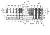
次に、図4を参照して、ベースモジュール2の構成について説明する。ベースモジュール2は、HFエネルギー分配ライン4と、データ通信分配配線5と、器具電圧分配配線6とを備える分配ユニットを備える。当該分配ユニット及びベースモジュール2は、本発明に係る高電圧接続部に相当する。
Next, the configuration of the
HFエネルギー分配ライン4は、高周波及び高電圧用に構成された3つのストライプ導体を備えるバスバー40を備え、図示の例示的な実施形態では、第1の導体41はアクティブ電極41用であり、第2の導体は中性電極42として構成され、第3の導体43は第2のアクティブ電極として構成される。ストライプ導体は、比較的幅広に寸法設定され、医療用のデバイスに必要とされる(通常、それぞれの国の規制によって要求される)絶縁に十分な間隔45だけ互いに分離される。インバータユニット27によって生成されるHFエネルギーは、HFエネルギー供給ケーブル28を介して、バスバー40の全ての導体41、42、43にわたってベースモジュール2の縁部に近接して位置するHF入力端子22に、ベースモジュール2のHFエネルギー分配ライン4に供給される。これにより、インバータユニット27で生成された高周波電力は、ベースモジュール2のHFエネルギー分配ライン4に直接供給される。
The HF
バスバー40のストライプ導体に実質的に平行に、器具電圧分配配線6がベースモジュール2上に位置する。この器具電圧分配配線6は、電源バスバー60として平行に配置されたより小さい導体46のセットを備え、これらの導体は、12VのDC電源及び5Vの電力のように、それぞれのサブモジュール7上の器具回路を動作させるために電力を伝導するように構成される。これらの電圧は、電源ユニット21から供給され、ケーブル68及び器具電圧供給端子62によって器具電圧分配配線6に伝達され、器具電圧分配配線6の導体は、直接又はDC/DCコンバータによって器具電圧供給端子62に接続される。
Substantially parallel to the stripe conductors of the
更に、ベースモジュール2上に設けられたデータ通信分配配線5は、HFエネルギー分配ライン4及び器具電圧分配配線6と平行に延びる種々のラインを有するデータバスバー50を備える。これは、動作制御ユニット20に接続されたデータ端子52に接続されている。例示的な実施形態では、データバスは、好ましくは非常に低い通信速度(CAN-Low)を有するCAN(コントロールエリアネットワーク)バスとして構成され、制御ユニット20への接続は、高い通信速度(CAN-High)を特徴とする。この目的のために、端子52は、任意選択で、高/低通信コンバータ53を備えることができる。
Furthermore, the data
更に、図4に示される実施形態では、ベースモジュール2は、任意のデバイス、すなわち、ベースモジュール2の動作を制御するように構成されたマイクロプロセッサ24を更に備える。
Furthermore, in the embodiment shown in FIG. 4, the
ここで本発明の重要な態様を参照すると、複数の接続ポートがベースモジュール2に設けられている。これらの各々は、任意のガイド80と、HFエネルギー分配ライン4への接点セット84と、データ通信分配配線5への接点セット85と、器具電圧分配配線6への接点セット86とを備える。任意のガイド80は、それぞれのサブモジュール7を機械的に受け入れるように構成され、当該サブモジュール7は、その挿入された状態で、それぞれ当該接続ポート及びその接点セット84、85及び86を介して、HFエネルギー分配ライン4、データ通信分配配線5及び器具電圧分配配線6に電気的に接続される。接続ポートの好ましい実施形態は、図3に示すようなハイブリッドコネクタ8である。それは、複数のセクション、すなわち、接点セット84のためのHFエネルギーセクション81と、CANプラグとして具現化され得る接点セット85のためのデータセクション82と、12V、5V、及び接地接点を備え得る接点セット86のための補助電圧セクション83とを備える単一のコネクタである。種々のセクション81、82、83は、好ましくは、内壁89によって互いに区切られる。更に好ましくは、ハイブリッドコネクタ8内に、間隔セクション88が設けられる。これは、繊細な低電圧及びデータ信号のための接点セット85、86を有するセクション82及び83から、HFエネルギーセクション81及びその接点セット84における高電圧を更に絶縁するという目的を果たす。間隔セクション88は、アイソレータとして空気を使用する中空空間であってもよく、又は追加の絶縁のために非導電性材料によって充填されてもよい。ハイブリッドコネクタ8は、任意のガイド80を更に特徴とする。ハイブリッドコネクタ8は、それぞれのサブモジュール7をそれぞれのハイブリッドコネクタ8に挿入すると、全ての接続が自動的に行われるという利点を有する。
Turning now to the important aspects of the invention, a number of connection ports are provided on the
ハイブリッドコネクタ8は、同一に構成され、ハイブリッドコネクタの各々は、サブモジュールのいずれかを受け入れることができる。この目的のために、ハイブリッドコネクタ8の各々は、接点セット84、85、及び86の全てを提供するが、それぞれの接点セットのうちのどの接点セットが実際に使用されるかは、挿入されるサブモジュール7のタイプに依存する。それによって、同じ又は異なるサブモジュール7を利用することに関して大きな柔軟性がもたらされる。この柔軟性は、任意の拡張モジュール9によって更に強化することができる。これは、ベースモジュール2と同様の分配ライン及び配線を備え、当該分配ライン及び配線に接続される少なくとも1つの追加のハイブリッドコネクタ8’を更に提供するという点で、ベースモジュール2と同様に構成される。拡張モジュール9をベースモジュール2に接続するために、インターフェース3が設けられている。それは、ベースモジュール2の分配ライン及び配線4、5、6が拡張モジュール9の同様の分配ライン及び配線4’、5’、6’に接続されるように、拡張モジュール9をベースモジュール2に取り付けるように構成される。
The
これにより、追加のハイブリッドコネクタ8’が提供され、より多くのサブモジュール7を利用することができる。更に、それによって、以下で強調される特定の強化された機能が達成される。 This allows additional hybrid connectors 8' to be provided, making it possible to utilize more sub-modules 7. Furthermore, this allows certain enhanced functionality to be achieved, which will be highlighted below.
次に、第1の構成による拡張モジュール9に加えて、図3のベースモジュールの概略機能図を示す図5を参照する。ベースモジュール2の一部のみが、図の左側に示されており、分配ライン及び配線4、5、6を支持している。図の右側には、拡張モジュール9が示されており、図の中央には、拡張モジュール9をベースモジュール2に接続するインターフェース3が示されている。拡張モジュール9の分配ライン及び配線4’,5’,6’は、ベースモジュール2と同様に3つのストライプ導体41’、42’、43’を備え、更に補助ストライプ導体44を備える。更に、ハイブリッドコネクタ8’が設けられ、図示の例では、拡張モジュール9上に3つの追加のハイブリッドコネクタ8’がある。これらは、接点セット84、85、86を有するベースモジュール2上のハイブリッドコネクタ8と同様に構成され、接点セット84内に補助導体44への追加の接点84’を含む。
Reference is now made to FIG. 5, which shows a schematic functional diagram of the base module of FIG. 3 in addition to the
インターフェース3は、二重単極双投(SPDT)リレーとして構成された切替えスイッチ38を備える。これは、インターフェースライン31、31’、32、32’及び33によってベースモジュール2のストライプ導体41、42、43に接続されている。ライン33は、ベースモジュール2のストライプ導体43から始まり、拡張モジュール9のストライプ導体44に直接接続される。ベースモジュール2のストライプ導体41で始まるライン31及び31’は、いずれかのSPDTの接点の1つに接続され、一方、ライン32及び32’は、ストライプ導体42で始まり、いずれかのSPDTの他の接点に接続される。したがって、切替えスイッチ38の切り替え状態に応じて、ダブルSPDTは、ベースモジュール2のストライプ導体41を拡張モジュール9のストライプ導体41’に直線的に接続し、ベースモジュール2のストライプ導体42を拡張モジュール9のストライプ導体42’に直線的に接続するか、又は、ベースモジュール2のストライプ導体41を拡張モジュールのストライプ導体42’に交差接続し、ベースモジュール2のストライプ導体42を拡張モジュール9のストライプ導体41’に交差接続する。図5に示すような例示的な実施形態では、直線接続は切替えスイッチ38によって行われる。
The
インターフェース3は、スイッチを更に備え、拡張モジュール9の補助コネクタ44をストライプ導体43’に選択可能に接続するためのスイッチ37に更に接続される。
The
更に、ラインセット35によって、ベースモジュール2のデータ通信分配配線5は、拡張モジュール9のデータ通信分配配線5’に接続される。同様に、別のラインセット36によって、ベースモジュール2の器具電圧分配配線6は、拡張モジュール9の器具電圧分配配線6’に接続される。その結果、拡張モジュール9は、ベースモジュール2に完全に接続され、そのハイブリッドコネクタ8を提供するために、ベースモジュール2と同じ方法で追加のハイブリッドコネクタ8’を提供する。
Further, by a line set 35, the data
更に、HF入力端子22を有するベースモジュール2と同様に、拡張モジュール9は、それ自体のHF入力端子92を備える。拡張モジュール9がベースモジュール2に接続される場合、HFエネルギー供給ケーブル28は、ベースモジュール2のHF入力端子22ではなく、拡張モジュール9のHF入力端子92に配置される。これにより、補助導体44を含む全てのストライプ導体41、42、43に、電気外科用器具19用の高周波電力を供給することができ、切替えスイッチ38及びスイッチ37により、ベースモジュール2のストライプ導体41、42、43には、インターフェース3によって拡張モジュール9から逆行的にHF電力が供給される。
Furthermore, like the
図5に示す構成では、ベースモジュール2の最も左のハイブリッドコネクタ8に単極サブモジュール7が挿入され、次のハイブリッドコネクタ8に中性電極を提供するサブモジュール7が挿入される。ベースモジュール2の最も右側のハイブリッドコネクタ8には、プラズマ混合サブモジュール7が挿入される。それぞれのハイブリッドコネクタ8に配置されたサブモジュール7は、図ではディザリングによってマークされている。サブモジュール7とHFエネルギー分配ライン4の導体41、42、43(及び該当する場合は44)との間に確立された接触は、クロスハッチングで塗りつぶされた菱形によって示されており、塗りつぶされていない白抜きの菱形は、接触が行われていないことを表している。
In the configuration shown in FIG. 5, a
拡張モジュール9上では、2つの最も左のハイブリッドコネクタ8’にもサブモジュールが装着されており、一方は別の単極サブモジュール7を担持し、他方はプラズマ混合サブモジュール7を担持する。スイッチ37は、ストライプ導体43’及び44の両方がストライプ導体43と同様に中性電極を提供するように閉じられる。この構成は、「プラズマブレンド、単極ブリッジNE」と称される。
On the
図6では、ベースモジュール2及び拡張モジュール9の最も左のハイブリッドコネクタ8,8’に配置された1つの単極サブモジュール7を有する構成が示されている。更に、ベースモジュール2の最も右側のハイブリッドコネクタ8及び拡張モジュール9の中間のハイブリッドコネクタ8’には、ユニバーサルサブモジュール7が配置される。しかしながら、図5に示される第1の構成とは対照的に、図6に示される第2の構成では、切替えスイッチ38は、ベースモジュール2のストライプ導体42が拡張モジュール9のストライプ導体41’に接続され、ベースモジュール2のストライプ導体41が拡張モジュール9のストライプ導体42’に接続されるように、ライン31及び32と交差するその他の状態にある。これにより、ストライプ導体41、42は、ベースモジュール2と拡張モジュール9とで電気的に反転する。これにより、スイッチ37が図示されるように開いているとき、「独立した中性電極を有するユニバーサル二重アクティブ双極」を特徴とする構成が得られる。「二重単極」構成は、スイッチ37が閉じられた場合に達成される。
6 shows a configuration with one
図7には、著しく異なる第3の構成が示されている。この構成では、電気外科用ジェネレータ1は、超音波電気外科用器具に供給するための超音波構成で構成される。サブモジュール7は、ベースモジュール2のハイブリッドコネクタ8のいずれにも配置されず、むしろ、超音波サブモジュール7は、拡張モジュール9のハイブリッドコネクタ8’の1つに配置される。切替えスイッチ38は、ストレート接続状態である。スイッチ37はその開状態にあり、それによって拡張モジュール9のストライプ導体43’及び44を分離する。したがって、超音波エネルギーを含むHF入力端子92を介してストライプ導体44に供給されるHFエネルギーは、拡張モジュール9上のハイブリッドコネクタ8’内に配置された超音波サブモジュール7のそれぞれの接点に伝達される。これにより、対応する超音波サブモジュール7を拡張モジュール9のハイブリッドコネクタ8内に配置することによって、「超音波構成」の変形形態を製造することができる。
7 shows a third configuration, which is significantly different. In this configuration, the
サブモジュール7の適切なアクティブ化のために、イネーブルライン55が、拡張モジュール9と同様にベースモジュール2上に設けられる。このイネーブルライン55は、接続ポート、すなわちハイブリッドコネクタ8、8’を介して、それぞれのサブモジュール7上のリレー78にルーティングされる。リレー78は、それぞれのハイブリッドコネクタ8,8’を介してそれぞれのサブモジュール7に供給されるHFエネルギーを伝達又は遮断するように構成される。イネーブルライン55は、サブモジュール7が、例えば、互換性チェックに合格することによって、アクティブ化されると判定される場合、HFエネルギーを伝達するためのリレーをオンに切り替えるために利用されてもよい。この目的のために、ベースモジュール2のマイクロプロセッサ24は、それぞれのハイブリッドコネクタ8,8’内に配置されているそれぞれのサブモジュール7からデータ通信分配配線5,5’を介して識別データを問い合わせる。マイクロプロセッサ24は、ベースモジュール2に設けられたアクティブ化制御ユニット25と協働し、それによって、サブモジュール構成を識別し、アクティブ化制御ユニット25に取り付けられたメモリ26に記憶された1つ又は複数の基準構成に対して、識別された構成の有効性をチェックする。対応する基準構成が見つかった場合、アクティブ化制御ユニット25は、現在のサブモジュール構成が有効であると判定し、対応する信号をマイクロプロセッサ24に提供する。有効性が確立されると、対応するアクティブ化信号が、有効であることが見出されたそれぞれのサブモジュール7にイネーブルライン55を介して送信され、それぞれのサブモジュール7に設けられたリレー78が通電されて、HFエネルギーの流れを可能にする。基準構成に属さない任意のサブモジュール7は、イネーブルライン55を介してイネーブル信号を受信せず、したがって、アクティブ化されない。これにより、サブモジュール7の構成の完全性が検証され、維持される。したがって、1つ又は複数の基準構成に適合しない任意の「不良」サブモジュールはアクティブ化されない。これにより、操作の柔軟性及び安全性が向上する。
For proper activation of the
ベースモジュール2は、図2A及び図2B並びに図4~図7に示すようなプリント回路基板として具現化されてもよい。それによって、接続ポート、特にハイブリッドコネクタ8のための適切な支持が提供され、サブモジュール7のための適切な機械的支持及び安定化を達成することができる。しかしながら、ベースモジュール2のかかるハードな実施形態は必須ではない。それはまた、図8に示されるように、主にHFエネルギーのためのケーブルセットとハイブリッドコネクタ8とを備えるソフトな変形形態で構成されてもよい。更に、HF入力端子22、データ端子52、及び器具電圧端子62、並びに拡張モジュール9(図8には図示せず)に接続するためのインターフェース3が含まれる。これは、効率的に製造することができるコンパクトなベースモジュール2を提供する。
The
上述した実施形態では、本発明に係る接続ポートは、ハイブリッドコネクタによって構成されていたが、これに限らず、異なるタイプのサブモジュールであって、電極ラインの数及び/又は種類が異なるサブモジュールに接続可能であるようにユニバーサルコネクタとして構成しても構わない。また、当該異なるタイプのサブモジュールは、単極ソケットモジュール、双極ソケットモジュール、中性電極ソケットモジュール、及び/又は汎用ソケットモジュールを含む。 In the above-described embodiment, the connection port according to the present invention is configured by a hybrid connector, but this is not limited thereto, and the connection port may be configured as a universal connector so as to be connectable to different types of submodules having different numbers and/or types of electrode lines. The different types of submodules include monopolar socket modules, bipolar socket modules, neutral electrode socket modules, and/or universal socket modules.
1,1´ 電気外科用ジェネレータ
2 ベースモジュール
3 インターフェース
4,4’ HFエネルギー分配ライン
5,5’ データ通信分配配線
6,6’ 器具電圧分配配線、分配ユニット、配線
7 サブモジュール
8,8’ ハイブリッドコネクタ
9 拡張モジュール
11 ハウジング
12 プラグ
13 電源ケーブル
14,14’ ユーザインターフェース
15 ディスプレイ
16 ノブ
17,17’,17’’ 出力ソケット
19 電気外科用器具
20 制御ユニット
21 電源ユニット
22 HF入力端子
24 マイクロプロセッサ
25 アクティブ化制御ユニット
26 メモリ
27,27’ インバータユニット
28 HFエネルギー供給ケーブル
31,31’,32,32’,33 インターフェースライン
35,36 ラインセット
37 スイッチ
38 切替えスイッチ
40 バスバー
41,41’,42,42’,43,43’ ストライプ導体
44 補助導体
45 間隔
46 導体
50 データバスバー
52 データ端子
53 高/低通信コンバータ
55 イネーブルライン
60 電源バスバー
62 器具電圧供給端子
68 ケーブル
71 プリント回路基板
72 相互接続ケーブル
73 信号リード
78 リレー
80 ガイド
81 第1のセクション
82 第2のセクション
83 第3のセクション
84 接点セット
84’ 追加の接点
85,86 接点セット
88 間隔セクション
89 内壁
92 HF入力端子
1, 1'
Claims (19)
前記高電圧接続部は、分配ユニットと、少なくとも1つの接続ポートが設けられたベースモジュールと、を備え、
前記分配ユニットは、HFエネルギー分配ラインと、データ信号のためのデータ通信分配配線と、を備え、前記インバータユニットから供給された前記HFエネルギー並びに前記データ信号を前記少なくとも1つの接続ポートに分配するように構成され、
前記少なくとも1つの接続ポートは、サブモジュールに接続され、前記出力ソケットに前記HFエネルギーを供給する前記サブモジュールに前記HFエネルギー及び前記データ信号を伝達するように構成される、電気外科用ジェネレータ。 An electrosurgical generator configured to output HF energy to an electrosurgical instrument, comprising: an inverter unit generating the HF energy output to the electrosurgical instrument; and a high voltage connection supplying the HF energy via at least two electrode lines to at least one output socket configured for connection of the electrosurgical instrument,
The high voltage connection section comprises a distribution unit and a base module provided with at least one connection port,
The distribution unit includes an HF energy distribution line and a data communication distribution wiring for a data signal, and is configured to distribute the HF energy and the data signal provided from the inverter unit to the at least one connection port;
The at least one connection port is connected to a sub-module and configured to transmit the HF energy and the data signal to the sub-module which supplies the HF energy to the output socket.
Applications Claiming Priority (2)
| Application Number | Priority Date | Filing Date | Title |
|---|---|---|---|
| US202263434989P | 2022-12-23 | 2022-12-23 | |
| US63/434,989 | 2022-12-23 |
Publications (1)
| Publication Number | Publication Date |
|---|---|
| JP2024091500A true JP2024091500A (en) | 2024-07-04 |
Family
ID=89223115
Family Applications (1)
| Application Number | Title | Priority Date | Filing Date |
|---|---|---|---|
| JP2023207824A Pending JP2024091500A (en) | 2022-12-23 | 2023-12-08 | Electrosurgical Generators |
Country Status (4)
| Country | Link |
|---|---|
| US (1) | US20240206947A1 (en) |
| EP (1) | EP4389042A1 (en) |
| JP (1) | JP2024091500A (en) |
| CN (1) | CN118236150A (en) |
Citations (5)
| Publication number | Priority date | Publication date | Assignee | Title |
|---|---|---|---|---|
| JPH04231037A (en) * | 1990-12-27 | 1992-08-19 | Sumitomo Bakelite Co Ltd | Surgical apparatus |
| JP2000271135A (en) * | 1999-01-19 | 2000-10-03 | Olympus Optical Co Ltd | Ultrasonosurgery system |
| JP2000515050A (en) * | 1996-08-29 | 2000-11-14 | バウシュ アンド ロンブ サージカル,インク. | Surgical module with neuron chip communication device |
| JP2001314411A (en) * | 2000-02-29 | 2001-11-13 | Olympus Optical Co Ltd | Surgical operation system |
| JP2003199763A (en) * | 1991-06-07 | 2003-07-15 | Vital Medical Products Corp | Electrosurgical apparatus using constant voltage |
Family Cites Families (3)
| Publication number | Priority date | Publication date | Assignee | Title |
|---|---|---|---|---|
| US6251113B1 (en) * | 1996-08-29 | 2001-06-26 | Bausch & Lomb Surgical, Inc. | Ophthalmic microsurgical system employing surgical module employing flash EEPROM and reprogrammable modules |
| US11918269B2 (en) * | 2018-09-07 | 2024-03-05 | Cilag Gmbh International | Smart return pad sensing through modulation of near field communication and contact quality monitoring signals |
| US12369994B2 (en) * | 2021-03-30 | 2025-07-29 | Cilag Gmbh International | Modular energy system with multi-energy port splitter for multiple energy devices |
-
2023
- 2023-12-08 JP JP2023207824A patent/JP2024091500A/en active Pending
- 2023-12-13 CN CN202311722769.XA patent/CN118236150A/en active Pending
- 2023-12-14 EP EP23216791.6A patent/EP4389042A1/en active Pending
- 2023-12-21 US US18/391,952 patent/US20240206947A1/en active Pending
Patent Citations (5)
| Publication number | Priority date | Publication date | Assignee | Title |
|---|---|---|---|---|
| JPH04231037A (en) * | 1990-12-27 | 1992-08-19 | Sumitomo Bakelite Co Ltd | Surgical apparatus |
| JP2003199763A (en) * | 1991-06-07 | 2003-07-15 | Vital Medical Products Corp | Electrosurgical apparatus using constant voltage |
| JP2000515050A (en) * | 1996-08-29 | 2000-11-14 | バウシュ アンド ロンブ サージカル,インク. | Surgical module with neuron chip communication device |
| JP2000271135A (en) * | 1999-01-19 | 2000-10-03 | Olympus Optical Co Ltd | Ultrasonosurgery system |
| JP2001314411A (en) * | 2000-02-29 | 2001-11-13 | Olympus Optical Co Ltd | Surgical operation system |
Also Published As
| Publication number | Publication date |
|---|---|
| EP4389042A1 (en) | 2024-06-26 |
| US20240206947A1 (en) | 2024-06-27 |
| CN118236150A (en) | 2024-06-25 |
Similar Documents
| Publication | Publication Date | Title |
|---|---|---|
| JP4607895B2 (en) | Control device for controlling medical electrical equipment | |
| US5573424A (en) | Apparatus for interfacing a bipolar electrosurgical instrument to a monopolar generator | |
| US10828087B2 (en) | Hand switched combined electrosurgical monopolar and bipolar device | |
| EP2289445B1 (en) | Electrosurgical generator with an isolating fiber optic connection circuit | |
| US5562503A (en) | Bipolar adaptor for electrosurgical instrument | |
| EP0694290B1 (en) | Electrosurgical apparatus | |
| US5342356A (en) | Electrical coupling unit for electrosurgery | |
| US8911437B2 (en) | Medical technology device and medical technology device arrangement | |
| US20120283720A1 (en) | Combined Bipolar and Monopolar Electrosurgical Instrument and Method | |
| JP6836859B2 (en) | Coagulation and incision device with improved control | |
| CN104519820A (en) | Electrosurgical instrument and system | |
| EP1018958A4 (en) | ELECTROSURGICAL ELECTRODE WITH CONCENTRATED ELECTRIC FIELD | |
| JP2024091500A (en) | Electrosurgical Generators | |
| US20240108395A1 (en) | Electrosurgical generator with modular output socket for electrosurgical instrument | |
| US20220370115A1 (en) | Electrosurgical generator | |
| WO2001037745A1 (en) | Switching appliance for electrosurgical devices | |
| JP2011070909A (en) | Switching device | |
| JP2018505593A (en) | RF high power generator | |
| CN223900840U (en) | Electrosurgical control system | |
| CN119074198B (en) | Surgical devices and systems compatible with electrosurgical and ultrasonic scalpels | |
| JPH09135843A (en) | Surgical operation device | |
| JP2020518316A (en) | Generator for outputting high frequency alternating current to medical devices | |
| KR200375091Y1 (en) | Electronic Apparatus having High Dielectric Capability | |
| TWM668889U (en) | Socket unit in extension cord and extension cord having the socket unit |
Legal Events
| Date | Code | Title | Description |
|---|---|---|---|
| A621 | Written request for application examination |
Free format text: JAPANESE INTERMEDIATE CODE: A621 Effective date: 20250410 |
|
| A977 | Report on retrieval |
Free format text: JAPANESE INTERMEDIATE CODE: A971007 Effective date: 20251009 |
|
| A131 | Notification of reasons for refusal |
Free format text: JAPANESE INTERMEDIATE CODE: A131 Effective date: 20251014 |
|
| A521 | Request for written amendment filed |
Free format text: JAPANESE INTERMEDIATE CODE: A523 Effective date: 20260105 |