JP2024075253A - Printing device, printing system, printing method and program - Google Patents
Printing device, printing system, printing method and program Download PDFInfo
- Publication number
- JP2024075253A JP2024075253A JP2022186567A JP2022186567A JP2024075253A JP 2024075253 A JP2024075253 A JP 2024075253A JP 2022186567 A JP2022186567 A JP 2022186567A JP 2022186567 A JP2022186567 A JP 2022186567A JP 2024075253 A JP2024075253 A JP 2024075253A
- Authority
- JP
- Japan
- Prior art keywords
- printing device
- printing
- illumination
- print medium
- Prior art date
- Legal status (The legal status is an assumption and is not a legal conclusion. Google has not performed a legal analysis and makes no representation as to the accuracy of the status listed.)
- Pending
Links
Images


Classifications
-
- B—PERFORMING OPERATIONS; TRANSPORTING
- B41—PRINTING; LINING MACHINES; TYPEWRITERS; STAMPS
- B41J—TYPEWRITERS; SELECTIVE PRINTING MECHANISMS, i.e. MECHANISMS PRINTING OTHERWISE THAN FROM A FORME; CORRECTION OF TYPOGRAPHICAL ERRORS
- B41J29/00—Details of, or accessories for, typewriters or selective printing mechanisms not otherwise provided for
- B41J29/18—Mechanisms for rendering the print visible to the operator
- B41J29/19—Mechanisms for rendering the print visible to the operator with reflectors or illuminating devices
-
- B—PERFORMING OPERATIONS; TRANSPORTING
- B41—PRINTING; LINING MACHINES; TYPEWRITERS; STAMPS
- B41J—TYPEWRITERS; SELECTIVE PRINTING MECHANISMS, i.e. MECHANISMS PRINTING OTHERWISE THAN FROM A FORME; CORRECTION OF TYPOGRAPHICAL ERRORS
- B41J2/00—Typewriters or selective printing mechanisms characterised by the printing or marking process for which they are designed
- B41J2/005—Typewriters or selective printing mechanisms characterised by the printing or marking process for which they are designed characterised by bringing liquid or particles selectively into contact with a printing material
- B41J2/01—Ink jet
-
- B—PERFORMING OPERATIONS; TRANSPORTING
- B41—PRINTING; LINING MACHINES; TYPEWRITERS; STAMPS
- B41J—TYPEWRITERS; SELECTIVE PRINTING MECHANISMS, i.e. MECHANISMS PRINTING OTHERWISE THAN FROM A FORME; CORRECTION OF TYPOGRAPHICAL ERRORS
- B41J3/00—Typewriters or selective printing or marking mechanisms characterised by the purpose for which they are constructed
- B41J3/44—Typewriters or selective printing mechanisms having dual functions or combined with, or coupled to, apparatus performing other functions
- B41J3/46—Printing mechanisms combined with apparatus providing a visual indication
Landscapes
- Accessory Devices And Overall Control Thereof (AREA)
- Ink Jet (AREA)
Abstract
【課題】印刷物の品質をより効率的に確認する。【解決手段】印刷装置が、印刷媒体に印刷データを印刷する印刷実行部と、印刷済みの印刷媒体に印刷面の裏側から照明光を照射する照明部と、を備える。【選択図】図13The present invention relates to a printing device that is capable of checking the quality of a printed matter more efficiently. The printing device includes a print execution unit that prints print data onto a print medium, and an illumination unit that irradiates the printed print medium with illumination light from behind the printed surface. (Selected Figure)
Description
本発明は、印刷装置、印刷システム、印刷方法及びプログラムに関する。 The present invention relates to a printing device, a printing system, a printing method, and a program.
従来より飲食店や小売店、デパート、ショッピングモール等の商業施設、アミューズメント施設等の娯楽施設、鉄道等の駅構内または公共施設等のさまざまな施設や繁華街では、例えば電飾パネルや電飾スタンド等の電飾広告メディア(内照式の看板とも称される)が用いられている。電飾広告メディアは、表面に配置した樹脂シート等の印刷物を、内部に配置した照明で印刷面の裏側から照らすことで、視認性を向上した広告メディアである。 Illuminated advertising media (also called internally illuminated signs), such as illuminated panels and illuminated stands, have traditionally been used in commercial facilities such as restaurants, retail stores, department stores, and shopping malls, entertainment facilities such as amusement facilities, railway stations, and public facilities, as well as in various facilities and downtown areas. Illuminated advertising media is advertising media that improves visibility by illuminating the back of the printed surface of a printed material such as a resin sheet placed on the surface with lighting placed inside.
電飾広告メディアは、内部の照明光や周囲の環境条件に応じて見え方が変化する。そのため、電飾広告メディアに用いる印刷物を印刷する印刷工場では、印刷装置から出力された印刷済みの印刷媒体に、手作業で照明光を当てながら印刷品質の確認を行っている。 The appearance of illuminated advertising media changes depending on the internal lighting and the surrounding environmental conditions. For this reason, at printing factories where the printed materials used for illuminated advertising media are printed, the print quality is checked by manually applying lighting to the printed media output from the printing device.
例えば、特許文献1には、印刷状態を容易に確認するために装置内部を照明する画像形成装置が開示されている。特許文献1に開示された画像形成装置は、画像形成媒体に画像を形成する画像形成部よりも上方に設けられ、画像形成媒体を搬送する搬送ローラの下流の部分を切断するカッターに照明光を照射する。
For example,
しかしながら、印刷媒体の利用環境を考慮しながら印刷品質を確認することは困難である。例えば、電飾広告メディアで用いる印刷物を印刷可能な印刷装置は、印刷済みの印刷媒体をロール状に巻き取る構造となっており、実際の利用環境を考慮して確認を行うためには印刷済みの印刷媒体を印刷装置から取り外さなければならない。なお、特許文献1に開示された画像形成装置は、装置内部で画像形成媒体の印刷面に照明光を照射するため、電飾広告メディアの利用環境を考慮しながら印刷品質を確認することはできない。
However, it is difficult to check the print quality while taking into account the usage environment of the print medium. For example, a printing device capable of printing printed materials used in illuminated advertising media is structured to wind up the printed print medium into a roll, and in order to check the quality while taking into account the actual usage environment, the printed print medium must be removed from the printing device. Note that the image forming device disclosed in
本発明の一実施形態は、印刷物の品質をより効率的に確認することを目的とする。 One embodiment of the present invention aims to more efficiently check the quality of printed matter.
本発明の一実施形態である印刷装置は、印刷媒体に印刷データを印刷する印刷実行部と、印刷済みの印刷媒体に印刷面の裏側から照明光を照射する照明部と、を備える。 A printing device according to one embodiment of the present invention includes a print execution unit that prints print data onto a print medium, and an illumination unit that irradiates the printed print medium with illumination light from behind the printed surface.
本発明の一実施形態によれば、印刷物の品質をより効率的に確認することができる。 According to one embodiment of the present invention, the quality of printed matter can be checked more efficiently.
以下、図面を参照しながら、この発明の実施の形態について、詳細に説明する。なお、図面中において同じ機能を有する構成部には同じ番号を付し、重複説明を省略する。 The following describes in detail an embodiment of the present invention with reference to the drawings. Note that components having the same functions in the drawings are given the same numbers, and duplicate explanations will be omitted.
[第1実施形態]
本発明の一実施形態は、例えば印刷工場等のように様々な印刷媒体に印刷を行う施設で用いられる印刷システムである。本実施形態における印刷工場は、例えば電飾パネル又は電飾スタンド等の電飾看板(電飾広告メディア)に用いる印刷物を製造する業務を行う。
[First embodiment]
One embodiment of the present invention is a printing system used in a facility that prints on various print media, such as a printing factory. The printing factory in this embodiment performs the business of manufacturing printed matter to be used for illuminated signs (illuminated advertising media), such as illuminated panels or illuminated stands.
<電飾広告メディアの概要>
本実施形態における電飾広告メディアについて、図1乃至図3を参照しながら説明する。図1乃至図3は、本実施形態における電飾広告メディアの第1の例乃至第3の例を示す模式図である。
<Outline of Illuminated Advertising Media>
The illuminated advertising medium in this embodiment will be described with reference to Fig. 1 to Fig. 3. Fig. 1 to Fig. 3 are schematic diagrams showing first to third examples of the illuminated advertising medium in this embodiment.
電飾広告メディアの第1の例は、電飾スタンドとも呼ばれる店頭看板である。図1に示されているように、第1の例における電飾広告メディア90は、外部から視認可能な側面に看板部91を有する。看板部91は、樹脂等の透過性を有する素材で形成されている。看板部91には、文字、図形及び写真等をレイアウトした画像が形成されている。電飾広告メディア90の内部には、LED等の光源が配置されており、光源から照射される照明光により看板部91に形成された画像が外部から視認される。
The first example of an illuminated advertising medium is a storefront signboard, also known as an illuminated stand. As shown in FIG. 1, the
なお、看板部91に画像を形成する方法は、看板部91を形成する樹脂等のパネルに画像を直接印刷してもよいし、透過性を有するシート状の印刷媒体に画像を印刷し、看板部91を形成するパネルに密着させてもよい。
The method of forming an image on the
図1には、電飾スタンドとも呼ばれる店頭看板の例を示したが、本実施形態における電飾広告メディアはこれに限定されない。例えば、鉄道施設等や小売店舗等に掲示される電飾パネル等であってもよい。 Figure 1 shows an example of a storefront sign, also known as an illuminated stand, but the illuminated advertising media in this embodiment is not limited to this. For example, it may be an illuminated panel displayed in railway facilities, retail stores, etc.
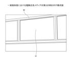
電飾広告メディアの第2の例は、商業施設に掲示される電飾パネルである。図2に示されているように、第2の例における電飾広告メディア90は、商業施設の壁面に固定され、商業施設内を往来する顧客等から視認可能な面に看板部91を有する。電飾パネルには、アルミニウム等のフレームで樹脂等のパネルが開閉可能に装着されており、パネルの壁面側にLED等の光源が配置されている。商業施設では、季節やセール等のイベントに際して頻繁に広告内容を切り替える必要がある。そのため、商業施設に掲示される電飾パネルは、容易に広告内容を切替できるように、広告内容を表す画像が形成された印刷物をパネルの内側に固着するように構成されている。
A second example of an illuminated advertising medium is an illuminated panel displayed in a commercial facility. As shown in FIG. 2, the
電飾広告メディアの第3の例は、鉄道施設に掲示される電飾パネルである。図3に示されているように、第3の例における電飾広告メディア90は、鉄道駅のプラットフォーム等の壁面に固定され、鉄道駅内を往来する乗降客等から視認可能な面に看板部91を有する。鉄道施設には、沿線の企業又は商業施設の広告が多く掲示され、広告主の事情に応じて広告内容を切り替えることが多い。そのため、鉄道施設に掲示される電飾パネルは、商業施設に掲示される電飾パネルと同様に、容易に広告内容を切替できるように構成されている。
A third example of an illuminated advertising medium is an illuminated panel displayed in a railway facility. As shown in FIG. 3, the
電飾広告メディアは、様々な利用環境で利用されているため、用途に応じて照明光の調整が行われている。例えば、店頭看板では、夜間なども遠方から確認できるように視認性が重要であるため、店頭看板に用いる光源は光量が高いものが使用される場合が多い。 Illuminated advertising media is used in a variety of environments, so the lighting is adjusted according to the application. For example, for storefront signs, visibility is important so that they can be seen from a distance, even at night, so light sources with high light output are often used for storefront signs.
例えば、鉄道施設では、利用客又は乗務員の安全性及び視作業性が重視される。そのため、鉄道施設に掲示される電飾広告メディアの光源は、演色性を重視して、例えばLED、メタルハライドランプ、高演色メタルハライドランプ、無電極蛍光ランプ、蛍光灯等を使用することが多い。また、車庫等の効率及び寿命等を重視する用途では、例えばLED又は無電極蛍光ランプ等を使用することが望ましい。鉄道施設では、用途に適した電飾パネルが各種の利用シーンで活用されるため、電飾パネルの光源も利用シーンに適した色温度及び光量に調整されている。 For example, in railway facilities, emphasis is placed on the safety and visual workability of passengers and crew members. For this reason, the light sources of illuminated advertising media displayed in railway facilities often emphasize color rendering, and are, for example, LEDs, metal halide lamps, high color rendering metal halide lamps, electrodeless fluorescent lamps, fluorescent lamps, etc. Also, in applications such as garages where efficiency and lifespan are important, it is desirable to use, for example, LEDs or electrodeless fluorescent lamps. In railway facilities, illuminated panels suited to the application are used in various usage scenarios, so the light sources of the illuminated panels are also adjusted to a color temperature and light intensity suited to the usage scenario.
例えば、商業施設では、時間帯又は季節により空間照明を最適化しているケースがある。例えば、朝は爽やかな雰囲気を演出するためにクリアな照明とし、夕方の活性期は賑わいを演出するために色温度を高めに設定し、昼間と夜間は色温度を低めに設定する等の制御が行われる。さらに、夏場は寒色系で涼しい雰囲気を演出し、冬場は暖色系で温かみのある雰囲気を演出することもある。商業施設では、空間演出に合わせて電飾パネルの光源も色温度及び光量が適切に調整される。 For example, in commercial facilities, spatial lighting is sometimes optimized depending on the time of day or season. For example, clear lighting is used to create a refreshing atmosphere in the morning, the color temperature is set higher to create a lively atmosphere during the active evening period, and the color temperature is set lower during the day and at night. Furthermore, cool colors may be used to create a cool atmosphere in the summer, and warm colors may be used to create a warm atmosphere in the winter. In commercial facilities, the color temperature and light intensity of the light sources in the illuminated panels are also appropriately adjusted to match the spatial presentation.
<電飾広告メディアに用いる印刷物の品質確認>
電飾広告メディアで用いる印刷物を製造する印刷工場では、印刷物を出力後、印刷済みの印刷媒体に形成された画像の品質を確認する。画像の品質は、例えば、スジやムラ等が発生した異常画像となっていないか、画像の色味が意図したとおりとなっているか等である。確認の結果、画像の品質に異常があることが判明した場合、異常と確認(判断)された印刷媒体は破棄することになる。その後、印刷設定を調整し、再度印刷を行う。したがって、例えば、印刷物の出力工程において、より早期に印刷品質の異常を検知できれば、再印刷でかかるインク、印刷媒体及び工数等のコストを削減することができる。
<Quality check of printed materials used in illuminated advertising media>
In a printing factory that produces printed matter used in illuminated advertising media, the quality of the image formed on the printed print medium is checked after the printed matter is output. The image quality is, for example, whether the image is abnormal with streaks or unevenness, and whether the color of the image is as intended. If the check reveals that there is an abnormality in the image quality, the print medium confirmed (determined) to be abnormal is discarded. After that, the print settings are adjusted and printing is performed again. Therefore, for example, if abnormalities in the print quality can be detected earlier in the output process of the printed matter, the costs of ink, print medium, labor, etc. required for reprinting can be reduced.
電飾広告メディアで用いる印刷物は、利用環境を考慮しながら印刷品質を確認することが困難である。電飾広告メディアは、表面に配置された印刷済みの印刷媒体を内部に配置された光源から照明光を照射することで、外部から視認されるメディアである。そのため、電飾広告メディアで用いる印刷物は、通常、照明光により白く飛ぶことがないように、高い印刷濃度で印刷されることが多い。印刷濃度が高いと自然光の下ではスジやムラ等の異常を確認することは困難である。電飾広告メディアにおける利用環境を考慮すると、印刷済みの印刷媒体に印刷面の裏側から照明光を照射しつつ印刷面側から印刷品質を確認することが重要である。 It is difficult to check the print quality of printed matter used in illuminated advertising media while taking into account the usage environment. Illuminated advertising media is a medium that can be viewed from the outside by shining illumination light from a light source placed inside the medium onto the printed medium placed on the surface. For this reason, printed matter used in illuminated advertising media is usually printed with a high print density so that it does not become white out due to the illumination light. When the print density is high, it is difficult to check for abnormalities such as streaks and unevenness under natural light. Considering the usage environment of illuminated advertising media, it is important to check the print quality from the printed surface side while shining illumination light onto the printed medium from the back side of the printed surface.
一方で、電飾広告メディア等で用いる印刷物を印刷可能な印刷装置は、印刷済みの印刷媒体をロール状に巻き取る構造となっている。そのため、現状(従来の)印刷工場では、印刷装置から出力された印刷済みの印刷媒体を印刷装置から取り外し、手作業で照明光を当てながら、色味や濃度等の見え方を確認することが行われている。 On the other hand, printing devices capable of printing printed materials used in illuminated advertising media and the like are structured to wind up the printed print medium into a roll. For this reason, currently (conventional) printing factories remove the printed print medium that has been output from the printing device and manually check the appearance of the color, density, etc. by shining a light on it.
従来の印刷工場におけるこのような印刷物の品質確認方法は、手間がかかり、かつ、非効率であることが課題となっている。印刷がすべて完了した後に印刷品質を確認すると、仮に印刷品質に問題があることが判明した場合、印刷濃度等の印刷設定を調整し、すべての印刷を再度実行する必要がある。 The problem with conventional methods of checking the quality of printed materials in printing factories is that they are time-consuming and inefficient. If the print quality is checked after all printing is completed, and a problem is found with the print quality, it is necessary to adjust print settings such as print density and perform all printing again.
また、電飾広告メディアは、光源の色温度や光量が様々である。例えば、電飾広告メディアは、設置場所(屋内又は屋外等)、季節又は時間帯等の相違により見え方が異なる。また、例えば、設置される空間の総合的な演出を考慮して、電飾広告メディアの見え方を異ならせたい場合もある。そのため、電飾広告メディアで用いる印刷物の印刷品質を確認するときには、電飾広告メディアの仕様及び設置環境等に合わせた確認を行う必要がある。 In addition, illuminated advertising media have a variety of light source color temperatures and light intensity. For example, illuminated advertising media looks different depending on the installation location (indoors or outdoors, etc.), the season, or the time of day. In addition, for example, there are cases where it is desired to change the appearance of illuminated advertising media, taking into account the overall presentation of the space in which it is installed. For this reason, when checking the print quality of printed matter used in illuminated advertising media, it is necessary to check in accordance with the specifications of the illuminated advertising media and the installation environment, etc.
本発明の一実施形態は、電飾広告メディア等で用いる印刷物の印刷品質を確認する工程における課題を解決するものである。一実施形態における印刷装置は、印刷装置から出力される印刷済みの印刷媒体に、印刷面の裏側から照明光を照射する。これにより、印刷装置のオペレータは、印刷を実行しながら印刷済みの印刷媒体の印刷品質を確認することができる。また、一実施形態における印刷装置は、利用環境に応じた照明光を印刷済みの印刷媒体に照射する。これにより、オペレータは、電飾広告メディア等の利用環境における見え方を確認することができ、精度よく(より利用環境に則した)印刷品質を確認することができる。 One embodiment of the present invention solves the problem in the process of checking the print quality of printed matter used in illuminated advertising media and the like. The printing device in one embodiment applies illumination light to the back side of the printed surface of the printed medium output from the printing device. This allows the operator of the printing device to check the print quality of the printed medium while printing is being performed. The printing device in one embodiment also applies illumination light that corresponds to the usage environment to the printed medium. This allows the operator to check how the printed medium will look in the usage environment of the illuminated advertising media and the like, and to check the print quality with high accuracy (more in line with the usage environment).
図4は、本実施形態における品質確認作業の一例を示す図である。図4(A)は、照明光を照射していない状態の印刷装置における品質確認作業の一例を示す図である。図4(B)は、照明光を照射している状態の印刷装置における品質確認作業の一例を示す図である。 Figure 4 is a diagram showing an example of quality confirmation work in this embodiment. Figure 4 (A) is a diagram showing an example of quality confirmation work in a printing device in a state where illumination light is not being emitted. Figure 4 (B) is a diagram showing an example of quality confirmation work in a printing device in a state where illumination light is being emitted.
図4(A)及び図4(B)に示されているように、電飾広告メディア等で用いる印刷物を印刷する印刷装置100は、正面下部から印刷済みの印刷媒体Mが出力され、ロール状に巻き取る構造となっている。印刷装置100を操作するオペレータOPは、印刷装置100の正面に立って作業することが多い。図4(A)に示されているように、電飾広告メディアで用いる印刷物は印刷濃度が高いため、照明光を照射していない状態では全体が黒く潰れて見え、その印刷品質を判断することは容易ではない。
As shown in Figures 4(A) and 4(B), the
図4(B)に示されているように、印刷媒体Mの印刷面の裏側(すなわち、印刷装置100の正面に立つオペレータOPから見て、印刷媒体Mの奥側)から照明光を照射すれば、オペレータOPは、印刷装置100から出力される印刷媒体Mが電飾広告メディア等で用いられたときの見え方を容易に確認することができる。印刷装置100は、正面に操作パネルが配置されているため、印刷品質に問題があることが判明すれば、オペレータOPは、即時に操作パネルを操作して印刷を停止することも可能である。
As shown in FIG. 4(B), by shining illumination light from the back side of the printed surface of the print medium M (i.e., the back side of the print medium M as seen by the operator OP standing in front of the printing device 100), the operator OP can easily check how the print medium M output from the
<印刷システムの全体構成>
本実施形態における印刷システムの全体構成について、図5を参照しながら説明する。図5は、本実施形態における印刷システムの全体構成の一例を示す概念図である。
<Overall configuration of printing system>
The overall configuration of the printing system in this embodiment will be described with reference to Fig. 5. Fig. 5 is a conceptual diagram showing an example of the overall configuration of the printing system in this embodiment.
図5に示されているように、本実施形態における印刷システム1000は、印刷装置100及びユーザ端末200を含む。印刷装置100及びユーザ端末200は、それぞれ通信ネットワークN1に接続している。通信ネットワークN1は、接続されている各装置が相互に通信可能となるように構成されている。
As shown in FIG. 5, the
通信ネットワークN1は、例えば、インターネット、LAN(Local Area Network)、又はWAN(Wide Area Network)等の有線通信によるネットワークによって構築されている。通信ネットワークN1は、有線通信だけでなく、例えば、無線LAN、又は近距離無線通信等の無線通信、もしくはWiMAX(Worldwide Interoperability for Microwave Access)、LTE(Long Term Evolution)、又は5G(5th Generation)等の移動体通信によるネットワークが含まれていてもよい。 The communication network N1 is constructed by a network using wired communication, such as the Internet, a local area network (LAN), or a wide area network (WAN). The communication network N1 may include not only wired communication, but also wireless communication, such as a wireless LAN or short-range wireless communication, or a network using mobile communication, such as Worldwide Interoperability for Microwave Access (WiMAX), Long Term Evolution (LTE), or 5th Generation (5G).
印刷装置100は、印刷媒体に印刷データを印刷する画像形成装置である。本実施形態における印刷装置は、搬送方向に搬送される記録媒体にヘッドから液体を吐出して画像を形成する液体吐出装置である。本実施形態における印刷装置の一例は、インクジェットプリンタ等である。印刷データは、印刷媒体に形成する文字、図形及び写真等がレイアウトされた画像を表す電子データである。
The
本実施形態における印刷媒体は、電飾広告メディアに用いることができる印刷媒体(電飾メディアとも呼ばれる)である。印刷媒体は、電飾広告メディアの内部から照射される照明光を電飾広告メディアの外部へ透過するように透過性を有する。透明又は半透明等の透過性の程度は、電飾広告メディアの用途等により任意に選択することができる。 The print medium in this embodiment is a print medium (also called an illuminated media) that can be used for illuminated advertising media. The print medium is transparent so that the illumination light irradiated from inside the illuminated advertising media is transmitted to the outside of the illuminated advertising media. The degree of transparency, such as transparency or translucency, can be selected as desired depending on the application of the illuminated advertising media, etc.
電飾広告メディアに用いる印刷媒体は、例えば、PET(ポリエチレンテレフタレート)系メディア、PVC(ポリ塩化ビニル)系メディア、又はテンションファブリック等の布系メディア等がある。例えば、PET系メディアであれば、例えば白色、乳白色、透明色等のように、透過性の異なるメディアを利用することができる。ただし、本実施形態における印刷媒体は、これらに限定されず、電飾広告メディアに用いられる様々な印刷媒体に適用することができる。 The print media used in illuminated advertising media include, for example, PET (polyethylene terephthalate)-based media, PVC (polyvinyl chloride)-based media, and cloth-based media such as tension fabric. For example, in the case of PET-based media, media with different translucencies, such as white, milky white, transparent, etc., can be used. However, the print media in this embodiment is not limited to these, and can be applied to various print media used in illuminated advertising media.
印刷装置100は、印刷ジョブに従って印刷データを印刷媒体に印刷する。本実施形態における印刷ジョブは、印刷する内容を表す印刷データ及び印刷枚数等の印刷設定を含む。印刷ジョブは、オペレータの操作により、ユーザ端末200から通信ネットワークN1を介して印刷装置100に入力される。印刷装置100は、操作パネルに表示される操作画面から、印刷ジョブに対して開始、一時停止、再開又は終了等の操作を行うことができる。
The
ユーザ端末200は、オペレータが操作する情報処理端末である。ユーザ端末200の一例は、コンピュータである。ユーザ端末200の他の例は、スマートフォン又はタブレット端末等である。
The
ユーザ端末200は、オペレータの操作に応じて、印刷ジョブを生成し、印刷装置100に送信する。ユーザ端末200は、印刷装置100から受信した印刷状態等を表すメッセージをオペレータに対して出力する。
The
ユーザ端末200は、通信機能を備えた装置であれば、情報処理装置に限られない。ユーザ端末200は、例えば、PJ(Projector:プロジェクタ)、IWB(Interactive White Board:相互通信が可能な電子式の黒板機能を有する白板)、デジタルサイネージ等の出力装置、HUD(Head Up Display)装置、産業機械、撮像装置、集音装置、医療機器、ネットワーク家電、自動車(Connected Car)、ノートPC(Personal Computer)、携帯電話、スマートフォン、タブレット端末、ゲーム機、PDA(Personal Digital Assistant)、デジタルカメラ、ウェアラブルPCまたはデスクトップPC等であってもよい。
The
なお、図5に示した印刷システム1000の全体構成は一例であって、用途や目的に応じて様々なシステム構成例があり得る。例えば、印刷装置100又はユーザ端末200が、印刷システム1000に複数台含まれていてもよい。図5に示す印刷装置100、ユーザ端末200のような装置の区分は一例である。
Note that the overall configuration of the
<印刷装置のハードウェア構成>
本実施形態における印刷装置のハードウェア構成について、図6乃至図9を参照しながら説明する。図6は、本実施形態における印刷装置の内部を透視して示す斜視図である。図7は、本実施形態における印刷装置の構成の一例を示す上面図である。図8は、本実施形態における印刷装置が備えるキャリッジの構成の一例を示す図である。図9は、本実施形態における印刷装置の構成の一例を示す側面図である。
<Hardware Configuration of Printing Device>
The hardware configuration of the printing device in this embodiment will be described with reference to Figs. 6 to 9. Fig. 6 is a perspective view showing the inside of the printing device in this embodiment. Fig. 7 is a top view showing an example of the configuration of the printing device in this embodiment. Fig. 8 is a diagram showing an example of the configuration of a carriage provided in the printing device in this embodiment. Fig. 9 is a side view showing an example of the configuration of the printing device in this embodiment.
図6乃至図9に示すように、印刷装置100は、ヘッド1、第1移動機構2、載置部材3、第2移動機構4、ライト5及び操作パネル16を有する。
As shown in Figures 6 to 9, the
印刷装置100は、例えば、液体の一例であるインクにより、印刷媒体Mに画像を形成するシリアル型の画像形成装置である。印刷装置100は、第2移動機構4により印刷媒体Mを第2方向Bに間欠的に搬送する。また、印刷装置100は、印刷媒体Mの搬送が停止している間に、第1移動機構2によりヘッド1を第1方向Aに往復移動させつつ、ヘッド1から載置部材3上の印刷媒体Mにインクを吐出することにより、印刷媒体M上に画像を形成する。
The
第1移動機構2は、キャリッジ21、駆動プーリ22、従動プーリ23及びタイミングベルト24を有し、印刷媒体Mとヘッド1とを第1方向Aに相対移動させる。
The
キャリッジ21は、印刷媒体Mとヘッド1とを第1方向Aに相対移動させる。図6に示すように、キャリッジ21は、第1方向Aに延設された主ガイドロッド6により支持され、第1方向Aに往復移動する。また、キャリッジ21には連結片21aが設けられている。連結片21aは、主ガイドロッド6と平行に設けられた副ガイド部材7に係合し、キャリッジ21の姿勢を安定化させる。
The
キャリッジ21は、駆動プーリ22と従動プーリ23との間に張架されたタイミングベルト24に連結している。駆動プーリ22は、第1モータ8の駆動により回転する。従動プーリ23は、駆動プーリ22との間の距離を調整する機構を有し、タイミングベルト24に対して所定のテンションを与える機能を有する。
The
キャリッジ21は、第1モータ8の駆動によりタイミングベルト24が送り動作を行うことにより、第1方向Aに往復移動できる。キャリッジ21の移動量や移動速度は、例えば図7に示すように、キャリッジ21に設けられたエンコーダセンサ10がエンコーダシート11のマークを検知して出力するエンコーダ値に基づいて制御される。
The
図8に示すように、キャリッジ21は、ヘッド1A、1B及び1Cを含む3つのヘッド1を搭載している。図8は、キャリッジ21に向き合う印刷媒体M側から視たキャリッジ21を示している。ヘッド1は、印刷媒体Mにインクを吐出する。
As shown in FIG. 8, the
ヘッド1Aは、イエロー(Y)インクを吐出する複数のノズルを並べたノズル列1Ay、シアン(C)インクを吐出する複数のノズルを並べたノズル列1Ac、マゼンタ(M)インクを吐出する複数のノズルを並べたノズル列1Am、及びブラック(K)インクを吐出する複数のノズルを並べたノズル列1Akを一列ずつ有する。同様に、ヘッド1Bは、ノズル列1By、ノズル列1Bc、ノズル列1Bm及びノズル列1Bkを一列ずつ有し、ヘッド1Cは、ノズル列1Cy、ノズル列1Cc、ノズル列1Cm及びノズル列1Ckを一列ずつ有する。3つのヘッド1は、各ノズルが印刷媒体M側に向くように、キャリッジ21に支持されている。
ヘッド1A、1B、1Cは、第1方向A及び第2方向Bのそれぞれに並んで配置されている。このような配置により、印刷装置100は、キャリッジ21の第1方向Aへの1回の移動において、印刷媒体Mの広い領域に画像を形成できる。
The
図6において、ヘッド1にインクを供給するためのインク供給体であるカートリッジ9は、キャリッジ21には搭載されず、印刷装置100内の所定の位置に配置されている。カートリッジ9と3つのヘッド1のそれぞれはパイプで連結されており、このパイプを介して、カートリッジ9からヘッド1に対してインクが供給される。
In FIG. 6, the
第1方向Aにおけるキャリッジ21を挟んでカートリッジ9の反対側には、ヘッド1の信頼性を維持するための維持機構12が設けられている。維持機構12は、3つのヘッド1の吐出面の清掃やキャッピング、3つのヘッド1からの不要なインクの排出等を行う。
On the opposite side of the
図9に示すように、載置部材3は、印刷媒体Mを載置する載置部材の一例である。載置部材3は箱状部材であり、3つのヘッド1に向き合う載置面31上に印刷媒体Mを載置する。載置部材3は、載置面31に略直交する方向に貫通する貫通孔が複数形成されている。印刷装置100は、載置部材3の内側に設けられた吸引ファン13を作動させて載置面31に印刷媒体Mを吸着することにより、載置部材3上から印刷媒体Mが脱落することを抑制できる。
As shown in FIG. 9, the mounting
第2移動機構4は、巻出部41、駆動ローラ42、従動ローラ43及び巻取部44を有し、印刷媒体Mと3つのヘッド1とを第1方向Aに交差する第2方向Bに相対移動させる。第2移動機構4は、駆動ローラ42及び従動ローラ43を用いて、巻出部41から巻き出される印刷媒体Mを、載置部材3を介して巻取部44へ間欠的に搬送することにより、印刷媒体Mと3つのヘッド1とを相対移動させる。
The
巻出部41は、芯部材である紙管などの中空軸部に印刷媒体Mをロール状に巻き付けたロール体を含み、ロール体の回転によりロールから印刷媒体Mを巻き出す。
The unwinding
駆動ローラ42は、第2モータにより回転駆動される。従動ローラ43は、駆動ローラ42の回転に従って従動回転する。印刷装置100は、駆動ローラ42と従動ローラ43との間に印刷媒体Mを挟んで挟持搬送できる。
The drive roller 42 is driven to rotate by the second motor. The driven
巻取部44は、芯部材である紙管などの中空軸を備え、印刷媒体Mの先端が中空軸にテープ等の接着部材等により接着されており、この中空軸に印刷媒体Mを巻き取ることができる。
The winding
印刷装置100は、第2方向Bにおける載置部材3の上流側および下流側に設けられた給紙ガイド部材14および排紙ガイド部材15によって、第2移動機構4による印刷媒体Mの搬送をガイドする。
The
ライト5は、排紙ガイド部材15と巻取部44との間において、排紙ガイド部材15から排紙される印刷済みの印刷媒体Mに、印刷面の裏側から照明光を照射する。ライト5は、光量及び色温度を調整することが可能な照明器具である。ライト5は、例えば、LED(Light Emitting Diode)照明器具である。
The
図10は、本実施形態におけるライトの一例を示す斜視図である。図10に示されているように、ライト5は、縦横比の大きい直方体であり、一側面において複数の光源5a~5jが長手方向に配列されている。各光源5a~5jは独立して点灯及び消灯が可能であり、光量及び色温度を個別に調整することが可能である。例えば、ライト5は、印刷媒体Mの幅に応じて照明光を照射する光源の幅を制御可能である。なお、図10には10個の光源を有するライト5の例を示したが、ライト5が有する光源の数は任意に増減することができる。
Figure 10 is a perspective view showing an example of a light in this embodiment. As shown in Figure 10, the
ライト5の光源5a~5jと反対側の側面には、各光源5a~5jに電源を供給する電源コード、及び印刷装置100を制御する制御装置50と接続する通信ケーブル等が接続されている。ライト5は、レール式のフレーム17に取り付けられており、フレーム17の長手方向における位置を調整可能となるように構成されている。フレーム17は中空状に形成されたダクトレール状に形成されてもよい。この場合、フレーム17の内部に電源コードや通信ケーブル等を収納しつつライト5の位置を調整することができる。
A power cord that supplies power to each of the
ライト5は、印刷装置100の正面に立つオペレータの視界に照明光が直接入らないように構成するとよい。例えば、ライト5は、排紙ガイド部材15寄りの高さ、かつ印刷装置100の正面から見て奥側の位置に配置するとよい。また、印刷媒体Mの幅よりも広く照明光が照射されないように、遮光部材を備えたり、照射角度を調整したりしてもよい。
The
ライト5は、印刷装置100に固定しないように配置するとよい。図9に示した例では、ライト5は印刷装置100と固定されていない載置台18に取り付けられている。ライト5を印刷装置100に固定しないように配置することで、印刷装置100の印刷時の振動によりライト5を構成する電子部品が消耗することを回避することができる。
The
本実施形態における印刷装置100を制御する制御装置50のハードウェア構成について、図11を参照しながら説明する。図11は、本実施形態における制御装置のハードウェア構成の一例を示すブロック図である。
The hardware configuration of the
制御装置50は、例えばコンピュータによって構築されており、CPU(Central Processing Unit)51と、ROM(Read Only Memory)52と、RAM(Random Access Memory)53と、HDD/SSD(Hard Disk Drive/Solid State Drive)54と、接続I/F(Interface)55と、通信I/F56と、を有する。これらは、システムバスCを介して相互に通信可能に接続している。
The
CPU51は、各種の演算処理を含む制御処理を実行する。ROM52は、IPL(Initial Program Loader)等のCPU51の駆動に用いられるプログラムを記憶する。RAM53は、CPU51のワークエリアとして使用される。HDD/SSD54は、プログラム等の各種情報を記憶する。
The
接続I/F55は、制御装置50を各種の機器と接続するためのインターフェースである。ここでの機器は、ライト5等である。
The connection I/
通信I/F56は、通信ネットワーク等を介して、外部装置との間で通信するためのインターフェースである。例えば、制御装置50は、印刷媒体Mに形成する画像の元となる印刷データを通信I/F56を介してユーザ端末200等から受信できる。
The communication I/
なお、CPU51により実現される機能の少なくとも一部は、電気回路または電子回路により実現されてもよい。
At least some of the functions realized by the
<コンピュータのハードウェア構成>
本実施形態におけるユーザ端末200は、コンピュータにより実現される。図12は、ユーザ端末200がコンピュータで実現される場合のハードウェア構成の一例を示す図である。
<Computer hardware configuration>
The
図12に示されているように、本実施形態におけるコンピュータは、CPU501、ROM502、RAM503、HD504、HDD(Hard Disk Drive)コントローラ505、ディスプレイ506、外部機器接続I/F(Interface)508、ネットワークI/F509、バスライン510、キーボード511、ポインティング機器512、DVD-RW(Digital Versatile Disk Rewritable)ドライブ514、メディアI/F516を備えている。
As shown in FIG. 12, the computer in this embodiment includes a
これらのうち、CPU501は、コンピュータ全体の動作を制御する。ROM502は、IPL等のCPU501の駆動に用いられるプログラムを記憶する。RAM503は、CPU501のワークエリアとして使用される。HD504は、プログラム等の各種データを記憶する。HDDコントローラ505は、CPU501の制御にしたがってHD504に対する各種データの読み出し又は書き込みを制御する。
Of these,
ディスプレイ506は、カーソル、メニュー、ウィンドウ、文字、又は画像などの各種情報を表示する。外部機器接続I/F508は、各種の外部機器を接続するためのインターフェースである。この場合の外部機器は、例えば、USB(Universal Serial Bus)メモリやプリンタ等である。ネットワークI/F509は、通信ネットワークN1を利用してデータ通信をするためのインターフェースである。バスライン510は、図12に示されているCPU501等の各構成要素を電気的に接続するためのアドレスバスやデータバス等である。
The
また、キーボード511は、文字、数値、各種指示などの入力のための複数のキーを備えた入力手段の一種である。ポインティング機器512は、各種指示の選択や実行、処理対象の選択、カーソルの移動などを行う入力手段の一種である。なお、ディスプレイ506がタッチパネルによる操作可能なディスプレイである場合は、タッチ操作が入力手段となってもよい(後述する操作画面600における操作パネル16のディスプレイ表示についても同様である)。DVD-RWドライブ514は、着脱可能な記録媒体の一例としてのDVD-RW513に対する各種データの読み出し又は書き込みを制御する。なお、DVD-RWに限らず、DVD-R等であってもよい。メディアI/F516は、フラッシュメモリ等の記録メディア515に対するデータの読み出し又は書き込み(記憶)を制御する。
The
<印刷システムの機能構成>
本実施形態における印刷システムの機能構成の一例について、図13を参照しながら説明する。図13は、本実施形態における印刷システムの機能構成の一例を示すブロック図である。
<Functional configuration of the printing system>
An example of the functional configuration of a printing system in this embodiment will be described with reference to Fig. 13. Fig. 13 is a block diagram showing an example of the functional configuration of a printing system in this embodiment.
≪制御装置の機能構成≫
図13に示されているように、本実施形態における制御装置50は、ジョブ受付部101、利用情報受付部102、照射制御部103、印刷制御部104及び制御情報記憶部110を備える。
<Functional configuration of the control device>
As shown in FIG. 13, the
ジョブ受付部101、利用情報受付部102、照射制御部103及び印刷制御部104は、例えば、図12に示されているROM502からRAM503上に展開されたプログラムがCPU501及びネットワークI/F509に実行させる処理によって実現される。
The
制御情報記憶部110は、例えば、図12に示されているHD504を用いて実現される。HD504が記憶するデータの読み込み又は書き込みは、例えば、HDDコントローラ505を介して行われる。
The control
ジョブ受付部101は、ユーザ端末200から受信した印刷ジョブを受け付ける。本実施形態における印刷ジョブには、印刷媒体に形成する画像を表す印刷データが含まれる。
The
利用情報受付部102は、ユーザ端末200から受信した利用情報を受け付ける。本実施形態における利用情報は、印刷媒体の属性情報及び電飾広告メディアの利用環境を含む。印刷媒体の属性情報は、例えば、印刷媒体の透過性を表す情報である。印刷媒体の属性情報は、印刷媒体の種類、素材又は型番等、透過性を特定可能な情報であってもよい。電飾広告メディアの利用環境は、例えば、場所、季節、時間帯又は演出等、電飾広告メディアが視認される環境を表す情報である。
The usage
照射制御部103は、利用情報受付部102が受け付けた利用情報に基づいて、ライト5の光源から照射される照明光の照射条件を決定する。照射制御部103は、決定した照射条件に従ってライト5の光源を制御する。本実施形態における照射条件は、例えば、色温度及び光量等を含む。照射制御部103は、照射パターンを決定してもよい。本実施形態における照射パターンは、時間経過に伴い照明光の照射条件を変化させるパターンを表す情報である。
The
印刷制御部104は、ジョブ受付部101が受け付けた印刷ジョブに基づいて、印刷媒体に印刷データを印刷する。印刷制御部104は、ヘッド1、第1移動機構2及び第2移動機構4を制御することで、印刷装置100にセットされた印刷媒体Mに印刷データを印刷する。以降では、ヘッド1、第1移動機構2及び第2移動機構4を「印刷実行部」と総称することがある。
The
制御情報記憶部110には、ライト5の光源から照射される照明光を制御するための制御情報が予め記憶されている。本実施形態における制御情報は、属性条件及び利用条件を含む。属性条件は、印刷媒体の属性情報に応じた照射条件を定義する情報である。利用条件は、電飾広告メディアの利用環境に応じた照射条件を定義する情報である。属性条件は、制御情報記憶部110に記憶されている属性条件テーブルに格納される。利用条件は、制御情報記憶部110に記憶されている利用条件テーブルに格納される。
The control
≪ユーザ端末の機能構成≫
図13に示されているように、本実施形態におけるユーザ端末200は、ジョブ入力部201及び利用情報入力部202を備える。
<Functional configuration of user terminal>
As shown in FIG. 13, a
ジョブ入力部201及び利用情報入力部202は、例えば、図12に示されているROM502からRAM503上に展開されたプログラムがCPU501及びネットワークI/F509に実行させる処理によって実現される。
The
ジョブ入力部201は、オペレータによる操作に応じて、印刷ジョブの入力を受け付ける。ジョブ入力部201は、受け付けた印刷ジョブを印刷装置100に送信する。
The
利用情報入力部202は、オペレータによる操作に応じて、電飾広告メディアの利用情報の入力を受け付ける。利用情報入力部202は、受け付けた利用情報を印刷装置100に送信する。
The usage
<印刷方法の処理手順>
本実施形態における印刷方法の処理手順について、図14乃至図20を参照しながら説明する。図14は、本実施形態における印刷方法の処理手順の一例を示すフローチャートである。
<Printing method processing procedure>
The processing procedure of the printing method in this embodiment will be described with reference to Fig. 14 to Fig. 20. Fig. 14 is a flowchart showing an example of the processing procedure of the printing method in this embodiment.
ステップS1において、ユーザ端末200の利用情報入力部202は、印刷装置100のオペレータの操作に応じて、設定画面をディスプレイ506に表示する。設定画面を表示する操作は、例えば、メインメニュー等からメニューを選択する操作である。本実施形態における設定画面は、印刷媒体の属性情報及び電飾広告メディアの利用環境等を含む利用情報を設定するための設定画面である。
In step S1, the usage
≪設定画面≫
本実施形態における設定画面について、図15を参照しながら説明する。図15は、本実施形態における設定画面の一例を示す図である。
<Settings screen>
The setting screen in this embodiment will be described with reference to Fig. 15. Fig. 15 is a diagram showing an example of the setting screen in this embodiment.
図15に示されているように、本実施形態における設定画面400は、使用メディア選択欄401、利用シーン選択欄402、新規追加ボタン407、設定ボタン408及びキャンセルボタン409を有する。
As shown in FIG. 15, the
使用メディア選択欄401は、使用可能な印刷媒体の属性情報が、選択可能な態様で一覧表示される。図15に示した例では、使用メディア選択欄401には、印刷媒体の種類を排他的に選択可能なラジオボタンが表示されている。
The
利用シーン選択欄402は、想定される電飾広告メディアの利用環境が、選択可能な態様で一覧表示される。電飾広告メディアの利用環境は、分類ごとに選択可能としてもよい。図15に示した例では、利用シーン選択欄402には、場所及び時間帯の分類ごとに、利用環境を排他的に選択可能なラジオボタンが表示されている。
The usage
オペレータが新規追加ボタン407を押下すると、印刷媒体の属性情報又は電飾広告メディアの利用環境を追加するための画面が表示される。ユーザは予め登録されている印刷媒体の属性情報又は電飾広告メディアの利用環境とは異なるものを利用したいとき、当該画面を用いて印刷媒体の属性情報又は電飾広告メディアを新規に追加することができる。
When the operator presses the
オペレータが設定ボタン408を押下すると、使用メディア選択欄401で選択された印刷媒体の属性情報及び利用シーン選択欄402で選択された電飾広告メディアの利用環境を含む利用情報の入力が受け付けられる。オペレータがキャンセルボタン409を押下すると、利用情報は入力されず、設定画面400が閉じる。
When the operator presses the
図14に戻って説明する。ステップS1において、利用情報入力部202は、設定画面400においてオペレータが選択した利用情報を受け付ける。次に、利用情報入力部202は、受け付けた利用情報を印刷装置100に送信する。
Returning to FIG. 14, the explanation will be given. In step S1, the usage
ステップS2において、制御装置50の利用情報受付部102は、利用情報をユーザ端末200から受信する。次に、利用情報受付部102は、受信した利用情報を照射制御部103に送る。
In step S2, the usage
照射制御部103は、利用情報受付部102から利用情報を受け取る。次に、照射制御部103は、受け取った利用情報に基づいて、ライト5の光源から照射される照明光の照射条件を決定する。
The
照射制御部103は、まず、制御情報記憶部110に記憶されている制御情報を読み出す。制御情報には、属性条件及び利用条件が含まれる。次に、照射制御部103は、印刷媒体の属性情報が合致する属性条件を取得する。続いて、照射制御部103は、電飾広告メディアの利用環境が合致する利用条件を取得する。そして、照射制御部103は、取得した属性条件及び利用条件に基づいて、照射条件を決定する。
The
≪属性条件テーブル≫
本実施形態における属性条件テーブルについて、図16を参照しながら説明する。図16は、本実施形態における属性条件テーブルの一例を示す図である。
≪Attribute condition table≫
The attribute condition table in this embodiment will be described with reference to Fig. 16. Fig. 16 is a diagram showing an example of the attribute condition table in this embodiment.
図16に示されているように、本実施形態における属性条件の一例としての属性条件テーブルは、使用メディアと色味との組み合わせごとに、照明光の光量を表す情報を格納している。使用メディアは、印刷媒体の種類を表す情報であり、色味は照明光の色温度を表す情報である。 As shown in FIG. 16, an attribute condition table as an example of an attribute condition in this embodiment stores information that represents the amount of illumination light for each combination of the medium used and color. The medium used is information that represents the type of print medium, and the color is information that represents the color temperature of the illumination light.
本実施形態における属性条件テーブルでは、例えば色温度をケルビン(k)で定義し、光量をルクス(lx)で定義する。印刷媒体の種類は、電飾看板、鉄道施設又は空間照明等の用途により分類する例を示したが、印刷媒体の属性情報(図16の例では透過率)が異なる種類であればどのような分類で定義されていてもよい。言い替えると、図16に示した属性条件テーブルは、印刷媒体の透過率と照明光の色温度に応じて照明光の光量を定義する情報である。 In the attribute condition table in this embodiment, for example, color temperature is defined in Kelvin (k) and light quantity is defined in lux (lx). Although an example has been shown in which the types of print media are classified according to their uses, such as illuminated signs, railway facilities, or spatial lighting, any classification may be used as long as the types have different attribute information (transmittance in the example of FIG. 16). In other words, the attribute condition table shown in FIG. 16 is information that defines the light quantity of the illumination light according to the transmittance of the print medium and the color temperature of the illumination light.
例えば、電飾看板用の印刷媒体であれば、他の印刷媒体よりも透過率が高いため、光量は低め(例えば、1000~4000[lx])に設定されている。例えば、夏季に利用する電飾看板において、「青みが強い、クールかつ涼しげな演出」を目的として、昼光色(6500[k])を選択すれば、照明光の光量は4000[lx]となる。なお、照明光の色温度は光量とは独立して設定可能である。例えば、ライト5の前面にフィルター等を設置することで色温度を調整してもよい。
For example, the print media for illuminated signs has a higher transmittance than other print media, so the light intensity is set low (e.g., 1000 to 4000 [lx]). For example, for an illuminated sign to be used in the summer, if daylight color (6500 [k]) is selected for the purpose of creating a "strong bluish, cool and refreshing effect," the light intensity of the illumination will be 4000 [lx]. Note that the color temperature of the illumination light can be set independently of the light intensity. For example, the color temperature can be adjusted by placing a filter or the like in front of the
≪利用条件テーブル≫
本実施形態における利用条件の一例としての利用条件テーブルについて、図17乃至図19を参照しながら説明する。図17は、本実施形態における利用条件テーブルの第1の例を示す図である。利用条件テーブルの第1の例は、電飾広告メディアを設置する場所及び時間帯に応じて照射条件を調整するための利用条件を格納するテーブルである。以下、利用条件テーブルの第1の例を、「時間帯に関する利用条件テーブル」とも呼ぶ。
<<Usage Conditions Table>>
A usage condition table as an example of the usage conditions in this embodiment will be described with reference to Figs. 17 to 19. Fig. 17 is a diagram showing a first example of the usage condition table in this embodiment. The first example of the usage condition table is a table that stores usage conditions for adjusting the illumination conditions according to the location and time period where the illuminated advertising media is installed. Hereinafter, the first example of the usage condition table will also be referred to as a "usage condition table related to time period."
図17に示されているように、時間帯に関する利用条件テーブルは、場所と時間帯との組合せごとに、色温度及び光量を調整するための調整情報を格納している。利用条件テーブルに格納される調整情報は、光量の基準値に対して増減させる値と、色温度の基準値に対して増減させる割合とを含む。光量の基準値及び色温度の基準値は、属性条件テーブルにより決定される光量及び色温度である。 As shown in FIG. 17, the usage condition table for time periods stores adjustment information for adjusting color temperature and light intensity for each combination of location and time period. The adjustment information stored in the usage condition table includes the value to be increased or decreased relative to the reference value of light intensity, and the rate of increase or decrease relative to the reference value of color temperature. The reference value of light intensity and the reference value of color temperature are the light intensity and color temperature determined by the attribute condition table.
一例として、夏季に利用する電飾看板をオープンスペースで利用する利用シーンを説明する。この場合、属性条件テーブルにより、光量の基準値は4000[lx]、色温度の基準値は6500[k]に決定されている。利用条件テーブルによれば、オープンスペースに設置される場合、朝は光量及び色温度を基準値のまま使用する。また、昼は光量を基準値から1000[lx]減少させ(すなわち、3000[lx])、色温度を基準値の50%(すなわち、3250[k])に変更する。また、夕方は光量を基準値から1500[lx]減少させ(すなわち、2500[lx])、色温度を基準値の90%(すなわち、5850[k])に変更する。さらに、夜は光量を基準値から2500[lx]減少させ(すなわち、1500[lx])、色温度を基準値の70%(すなわち、4550[k])に変更する。 As an example, a usage scenario will be described in which an illuminated signboard for use in the summer is used in an open space. In this case, the attribute condition table has determined that the standard value of the light amount is 4000 [lx] and the standard value of the color temperature is 6500 [k]. According to the usage condition table, when the signboard is installed in an open space, the light amount and color temperature are used as the standard values in the morning. Furthermore, during the day, the light amount is reduced by 1000 [lx] from the standard value (i.e., 3000 [lx]) and the color temperature is changed to 50% of the standard value (i.e., 3250 [k]). Furthermore, in the evening, the light amount is reduced by 1500 [lx] from the standard value (i.e., 2500 [lx]) and the color temperature is changed to 90% of the standard value (i.e., 5850 [k]). Furthermore, at night, the light amount is reduced by 2500 [lx] from the standard value (i.e., 1500 [lx]) and the color temperature is changed to 70% of the standard value (i.e., 4550 [k]).
このようにすることで、電飾広告メディアを設置する場所及び時間帯に応じて調整すべき照射条件を決定することができる。なお、これらの場所及び時間帯などの利用環境は一例であり、必要とする環境に応じて任意に設定することができる。 In this way, it is possible to determine the illumination conditions that should be adjusted according to the location and time of day where the illuminated advertising media is installed. Note that these locations, time periods, and other usage environments are only examples, and can be set arbitrarily according to the required environment.
図18は、本実施形態における利用条件テーブルの第2の例を示す図である。利用条件テーブルの第2の例は、電飾広告メディアを設置する場所及びその場所で開催されるイベントの種別に応じて照射条件を調整するための利用条件を格納するテーブルである。以下、利用条件テーブルの第2の例を、「イベント種別に関する利用条件テーブル」とも呼ぶ。 Figure 18 is a diagram showing a second example of a usage condition table in this embodiment. The second example of the usage condition table is a table that stores usage conditions for adjusting the illumination conditions according to the location where the illuminated advertising media is installed and the type of event being held at that location. Hereinafter, the second example of the usage condition table is also referred to as the "usage condition table related to event type."
図18に示されているように、イベント種別に関する利用条件テーブルは、場所とイベント種別との組合せごとに、色温度及び光量を調整するための調整情報を格納している。イベント種別に関する利用条件テーブルは、例えば、活気、落ち着き、通常又はセール等の創出したい雰囲気に応じて調整情報を格納する。これらのイベント種別は一例であり、イベントの目的等に応じて任意に設定すればよい。 As shown in FIG. 18, the usage condition table for event types stores adjustment information for adjusting color temperature and light intensity for each combination of location and event type. The usage condition table for event types stores adjustment information according to the atmosphere that is desired to be created, such as lively, calm, normal, or sale. These event types are merely examples, and may be set arbitrarily according to the purpose of the event, etc.
イベント種別に関する利用条件テーブルは、時間帯に関する利用条件テーブルを補完する利用条件テーブルである。イベント種別に関する利用条件テーブルに従って決定された色温度及び光量は、時間帯に関する利用条件テーブルに従って決定された色温度及び光量よりも優先される。そのため、イベント種別に関する利用条件テーブルはすべての組合せについて調整情報が設定されていなくともよい。イベント種別に関する利用条件テーブルに調整情報が設定されていない場合、時間帯に関する利用条件テーブルに従って決定された色温度及び光量が利用される。 The usage condition table for event type is a usage condition table that complements the usage condition table for time period. The color temperature and light intensity determined according to the usage condition table for event type takes precedence over the color temperature and light intensity determined according to the usage condition table for time period. Therefore, the usage condition table for event type does not need to have adjustment information set for all combinations. If adjustment information is not set in the usage condition table for event type, the color temperature and light intensity determined according to the usage condition table for time period will be used.
図19は、本実施形態における利用条件テーブルの第3の例を示す図である。利用条件テーブルの第3の例は、電飾広告メディアを設置する場所及びその場所に陳列される商品の種別に応じて照射条件を調整するための利用条件を格納するテーブルである。以下、利用条件テーブルの第3の例を、「商品種別に関する利用条件テーブル」とも呼ぶ。 Figure 19 is a diagram showing a third example of a usage condition table in this embodiment. The third example of the usage condition table is a table that stores usage conditions for adjusting the illumination conditions according to the location where the illuminated advertising media is installed and the type of product displayed in that location. Hereinafter, the third example of the usage condition table is also referred to as the "usage condition table related to product type."
図19に示されているように、商品種別に関する利用条件テーブルは、場所と商品種別との組合せごとに、色温度及び光量を調整するための調整情報を格納している。商品種別に関する利用条件テーブルは、例えば、夏物、冬物、キッチン又はギフト等の商品イメージに応じて調整情報を格納する。これらの商品種別は一例であり、商品の属性や用途等に応じて任意に設定すればよい。 As shown in FIG. 19, the usage condition table for product types stores adjustment information for adjusting color temperature and light intensity for each combination of location and product type. The usage condition table for product types stores adjustment information according to product images, such as summer items, winter items, kitchen items, or gifts. These product types are just examples, and can be set arbitrarily according to product attributes, uses, etc.
商品種別に関する利用条件テーブルは、イベント種別に関する利用条件テーブルと同様に、時間帯に関する利用条件テーブルを補完する利用条件テーブルである。商品種別に関する利用条件テーブルに調整情報が設定されていない場合、時間帯に関する利用条件テーブルに従って決定された色温度及び光量が利用される。 The usage condition table for product type is a usage condition table that complements the usage condition table for time period, similar to the usage condition table for event type. If adjustment information is not set in the usage condition table for product type, the color temperature and light intensity determined according to the usage condition table for time period are used.
ここでは、イベント種別及び商品種別に応じて照明光の照射条件を調整する例を説明したが、これらは一例である。本実施形態における印刷装置100は、任意の観点に応じた利用条件テーブルを追加で定義してもよいし、時間帯に関する利用条件テーブルのみを定義してもよい。
Here, we have described an example of adjusting the illumination light irradiation conditions according to the event type and product type, but this is just one example. The
図14に戻って説明する。ステップS3において、制御装置50の照射制御部103は、ステップS2で取得した属性条件及び利用条件に基づいて、照射パターンを決定する。照射制御部103は、例えば、取得した利用条件が複数ある場合に、それらの利用条件に基づいて決定した複数の照射条件を、所定の時間間隔で切り替える照射パターンを決定する。照射制御部103は、取得した利用条件が1個である場合は、照射パターンを決定しなくてもよい。
Returning to FIG. 14, the explanation will be given. In step S3, the
例えば、照射制御部103は、時間帯の変化に応じて、照射条件を切り替える照射パターンを決定する。すなわち、時間帯に関する利用条件テーブルが定義されているとき、照射制御部103は、朝に対応する照射条件、昼に対応する照射条件、夕に対応する照射条件及び夜に対応する照射条件を順番に所定の時間間隔で切り替える照射パターンを決定する。このような照射パターンを使用することで、各時間帯における電飾広告メディアの見え方を容易に確認することが可能となる。
For example, the
ステップS4において、制御装置50の照射制御部103は、ステップS2で決定した照射条件及びステップS3で決定した照射パターンに基づいて、ライト5から照射される照明光を制御する。具体的には、照射制御部103は、照射条件で定められた色温度及び光量で照明光が照射されるようにライト5の光源を制御する。また、照射制御部103は、ステップS3で照射パターンを決定した場合、所定の時間間隔が経過するたびに照射パターンで定められた順番に従って照射条件を切り替えながら、ライト5の光源を制御する。
In step S4, the
ステップS5において、ユーザ端末200のジョブ入力部201は、オペレータによる操作に応じて、印刷ジョブの入力を受け付ける。次に、ジョブ入力部201は、受け付けた印刷ジョブを印刷装置100に送信する。
In step S5, the
ステップS6において、制御装置50のジョブ受付部101は、印刷ジョブをユーザ端末200から受信する。次に、ジョブ受付部101は、受信した印刷ジョブに対する操作を受け付ける操作画面を操作パネル16に表示する。
In step S6, the
≪操作画面≫
本実施形態における操作画面について、図20を参照しながら説明する。図20は、本実施形態における操作画面の一例を示す図である。
<Operation screen>
The operation screen in this embodiment will be described with reference to Fig. 20. Fig. 20 is a diagram showing an example of the operation screen in this embodiment.
図20に示されているように、本実施形態における操作画面600は、プレビュー表示欄601、部数選択欄602、開始ボタン603及び停止ボタン604を有する。本実施形態における操作画面600は、操作パネル16のディスプレイに表示される。
As shown in FIG. 20, the
プレビュー表示欄601には、印刷ジョブに含まれる印刷データで表される画像がプレビュー表示される。部数選択欄602は、印刷部数が変更可能な態様で表示される。図20に示した操作画面の例では、例えば、部数選択欄602の右隣のボタンを押下すると部数が増加し、左隣のボタンを押下すると部数が減少する。
The
オペレータが開始ボタン603を押下すると、印刷ジョブに従った印刷が開始する。オペレータが停止ボタン604を押下すると、実行中の印刷が停止する。開始ボタン603及び停止ボタン604は、一方が押下可能なときには他方が押下不可となるように排他的に制御してもよい。
When the operator presses the
図14に戻って説明する。ステップS6において、印刷制御部104は、操作画面600に対するオペレータの操作に応じて、印刷ジョブに従った印刷を開始する。印刷が開始すると、ヘッド1、第1移動機構2及び第2移動機構4が動作し、印刷装置100にセットされた印刷媒体Mに印刷データが印刷される。
Returning to FIG. 14, in step S6, the
ステップS7において、印刷装置100のオペレータは、印刷装置100から出力される印刷済みの印刷媒体Mを印刷装置100の正面側から観察し、印刷済みの印刷媒体Mの印刷品質を確認する。印刷済みの印刷媒体Mは、ライト5により印刷面の裏側から照明光を照射されているため、印刷装置100の正面側から観察したときの見え方は、電飾広告メディアにおける実際の利用環境(又は、より実際の利用環境に近い環境)を反映したものとなる。オペレータは印刷装置100の正面に立ち、出力される印刷済みの印刷媒体Mを観察すれば、電飾広告メディアの利用環境を考慮しながら印刷品質を確認することができる。
In step S7, the operator of the
ステップS8において、印刷装置100のオペレータは、印刷済みの印刷媒体Mの印刷品質が問題ないか否かを判定する。印刷品質に問題がない場合(YES)、オペレータは特段何もしなくてもよい。この場合、印刷装置100は印刷を続行し、ステップS11へ処理を進める。一方、印刷品質に問題がある場合(NO)、オペレータは操作画面600において停止ボタン604を押下する。この場合、印刷装置100はステップS9へ処理を進める。
In step S8, the operator of the
ステップS9において、制御装置50の印刷制御部104は、操作画面600に対するオペレータの操作に応じて、印刷を停止する。
In step S9, the
ステップS10において、制御装置50の照射制御部103は、オペレータの操作に応じて、照射条件を変更する。照射条件の変更は、オペレータが設定画面400において異なる利用情報を選択することで行ってもよいし、ユーザ端末200から属性条件テーブル又は利用条件テーブルにより定まる照射条件を変更することで行ってもよい。
In step S10, the
ステップS11において、制御装置50の印刷制御部104は、印刷を完了する。すなわち、操作画面600の部数選択欄602で選択された部数が印刷媒体Mに印刷され、ヘッド1、第1移動機構2及び第2移動機構4の動作が停止する。
In step S11, the
<第1実施形態の効果>
本実施形態における印刷装置100は、電飾広告メディアに用いる印刷済みの印刷媒体に印刷面の裏側から照明光を照射する。電飾広告メディアで用いる印刷物は、印刷面の裏側から照明光が照射されることで視認される。したがって、本実施形態における印刷装置100によれば、電飾広告メディアに用いる印刷物の品質を効率的に確認することができる。
Effects of the First Embodiment
The
本実施形態における印刷装置100は、印刷媒体の属性情報に応じて照明光の照射条件を決定する。例えば、印刷媒体の属性情報は透過性であり、照射条件は色温度及び光量である。したがって、本実施形態における印刷装置100によれば、電飾広告メディアに用いる印刷物の品質を、電飾広告メディアの属性情報を考慮しながら容易に確認することができる。
The
本実施形態における印刷装置100は、電飾広告メディアの利用環境に応じて照明光の照射条件を決定する。例えば、利用環境は、場所、季節、時間帯又は演出等である。したがって、本実施形態における印刷装置100によれば、電飾広告メディアに用いる印刷物の品質を、電飾広告メディアの利用環境を考慮しながら容易に確認することができる。
The
[第2実施形態]
本発明の第1実施形態では、ユーザにより入力された印刷媒体の属性情報及び電飾広告メディアの利用環境に基づいて、照明光の照射条件を決定する構成を説明した。本発明の第2実施形態では、印刷媒体の属性情報及び電飾広告メディアの利用環境と照明光の照射条件とを関連付ける設定情報を予め記憶しておき、ユーザにより選択された設定情報に従って照明光の照射条件を決定するように構成する。
[Second embodiment]
In the first embodiment of the present invention, a configuration has been described in which the irradiation conditions of the illumination light are determined based on the attribute information of the print medium and the usage environment of the illuminated advertising medium input by the user. In the second embodiment of the present invention, setting information that associates the attribute information of the print medium and the usage environment of the illuminated advertising medium with the irradiation conditions of the illumination light is stored in advance, and the irradiation conditions of the illumination light are determined according to the setting information selected by the user.
本実施形態における設定情報は、印刷媒体の属性情報及び電飾広告メディアの利用環境に対して、使用実績のある照射条件を関連付けたものである。使用実績のある照射条件の一例は、例えば、電飾広告メディア又は印刷媒体の製造者等が推奨する照射条件である。使用実績のある照射実績の他の例は、同一の依頼者に対して納品した過去の印刷物で使用した照射条件、又は依頼者と同種の業態で標準的に使用されている照射条件等である。 The setting information in this embodiment associates illumination conditions that have a proven track record with the attribute information of the print medium and the usage environment of the illuminated advertising media. An example of an illumination condition that has a proven track record is, for example, illumination conditions recommended by the manufacturer of the illuminated advertising media or the print medium. Other examples of illumination conditions that have a proven track record are illumination conditions used in past printed matter delivered to the same client, or illumination conditions that are standardly used in the same type of business as the client.
本実施形態における印刷装置100は、ある設定情報を用いて印刷を行い、印刷品質に問題があったときには、当該設定情報の照射条件を調整することができる。また、本実施形態における印刷装置100は、設定情報として登録されていない照射条件で印刷を行い、印刷品質に問題がなかったとき、当該照射条件を印刷媒体の属性情報及び電飾広告メディアの利用環境と関連付けて新たな設定情報として記憶することができる。本実施形態における印刷装置100によれば、使用実績のある設定情報の数及び精度を最適化することができる。
The
以下、本実施形態における印刷システム1000について、第1実施形態との相違点を中心に説明する。
The
<印刷システムの機能構成>
本実施形態における印刷システムの機能構成について、図21を参照しながら説明する。図21は、本実施形態における印刷システムの機能構成の一例を示すブロック図である。
<Functional configuration of the printing system>
The functional configuration of the printing system in this embodiment will be described with reference to Fig. 21. Fig. 21 is a block diagram showing an example of the functional configuration of the printing system in this embodiment.
≪制御装置の機能構成≫
図21に示されているように、本実施形態における制御装置50は、ジョブ受付部101、照射制御部103、印刷制御部104、設定情報管理部105、制御情報記憶部110及び設定情報記憶部111を備える。すなわち、本実施形態における制御装置50は、第1実施形態と比較すると、利用情報受付部102の代わりに設定情報管理部105を備え、設定情報記憶部111をさらに備える点が異なる。
<Functional configuration of the control device>
21 , the
設定情報記憶部111には、印刷媒体の属性情報及び電飾広告メディアの利用環境と照明光の照射条件とを関連付けた設定情報が記憶される。設定情報記憶部111には、予め1以上の設定情報が記憶されていてもよい。例えば、電飾広告メディア又は印刷媒体の製造者等により推奨される照射条件を含む設定情報を予め記憶しておくとよい。
The setting
設定情報管理部105は、オペレータにより選択された設定情報を設定情報記憶部111から読み出す。設定情報管理部105は、オペレータからの要求に応じて、設定情報を設定情報記憶部111に記憶する。
The setting
≪ユーザ端末の機能構成≫
図21に示されているように、本実施形態におけるユーザ端末200は、ジョブ入力部201及び設定情報選択部203を備える。すなわち、本実施形態におけるユーザ端末200は、第1実施形態と比較すると、利用情報入力部202の代わりに設定情報選択部203を備える点が異なる。
<Functional configuration of user terminal>
21, the
設定情報選択部203は、オペレータによる操作に応じて、設定情報の選択を受け付ける。設定情報選択部203は、受け付けた設定情報を印刷装置100に送信する。
The setting
<印刷方法の処理手順>
本実施形態における印刷方法の処理手順について、図22及び図23を参照しながら説明する。図22は、本実施形態における印刷方法の処理手順の一例を示すフローチャートである。
<Printing method processing procedure>
The processing procedure of the printing method in this embodiment will be described with reference to Fig. 22 and Fig. 23. Fig. 22 is a flowchart showing an example of the processing procedure of the printing method in this embodiment.
ステップS21において、ユーザ端末200の設定情報選択部203は、印刷装置100のオペレータの操作に応じて、設定画面をディスプレイ506に表示する。本実施形態における設定画面は、設定情報を選択するための設定画面である。
In step S21, the setting
≪設定画面≫
本実施形態における設定画面について、図23を参照しながら説明する。図23は、本実施形態における設定画面の一例を示す図である。
<Settings screen>
The setting screen in this embodiment will be described with reference to Fig. 23. Fig. 23 is a diagram showing an example of the setting screen in this embodiment.
図23に示されているように、本実施形態における設定画面410は、プロファイル選択欄411、設定ボタン418及びキャンセルボタン419を有する。
As shown in FIG. 23, the
プロファイル選択欄411には、設定情報記憶部111に記憶されている設定情報が、選択可能な態様で一覧表示される。図23に示した例では、プロファイル選択欄411には、顧客及び業種の組合せごとに、設定された印刷媒体の属性情報及び電飾広告メディアの利用環境が排他的に選択可能なラジオボタンと共に表示されている。
The
オペレータが設定ボタン418を押下すると、プロファイル選択欄411で選択された設定情報の選択が受け付けられる。オペレータがキャンセルボタン419を押下すると、設定情報は選択されず、設定画面410が閉じる。
When the operator presses the
図21の例では、顧客の業種ごとに設定情報が登録されている例を示したが、これらは一例である。本実施形態における印刷装置100は、任意の観点で設定情報を登録することができる。例えば、特定の顧客について季節、時間帯又はイベント単位で設定情報を登録してもよい。
The example in FIG. 21 shows setting information being registered for each type of business of a customer, but this is just one example. The
図22に戻って説明する。ステップS21において、設定情報選択部203は、設定画面410においてオペレータが選択した設定情報を受け付ける。次に、設定情報選択部203は、受け付けた設定情報を印刷装置100に送信する。
Returning to FIG. 22, the explanation will be given. In step S21, the setting
ステップS22において、制御装置50の設定情報管理部105が、設定情報をユーザ端末200から受信する。次に、設定情報管理部105は、受信した設定情報を照射制御部103に送る。照射制御部103は、設定情報管理部105から設定情報を受け取る。次に、照射制御部103は、受け取った設定情報に基づいて、ライト5の光源から照射される照明光の照射条件を決定する。
In step S22, the setting
照射制御部103は、まず、設定情報記憶部111に記憶されている設定情報を読み出す。次に、照射制御部103は、設定情報に含まれる印刷媒体の属性情報及び電飾広告メディアの利用環境を取得する。続いて、照射制御部103は、取得した属性情報及び利用環境に基づいて、制御情報記憶部110に記憶されている制御情報を読み出す。そして、照射制御部103は、読み出した制御情報に基づいて、照射条件を決定する。
The
ステップS23からS31までの処理は、第1実施形態における印刷方法(図14参照)のステップS3からS11までの処理と同様である。 The processing from steps S23 to S31 is the same as the processing from steps S3 to S11 in the printing method in the first embodiment (see FIG. 14).
ステップS32において、制御装置50の設定情報管理部105は、オペレータからの要求に応じて、設定情報を設定情報記憶部111に記憶する。設定情報管理部105は、印刷完了時の照射条件を、設定情報記憶部111に記憶する設定情報に含める。印刷完了時の照射条件は、ステップS22で決定された照射条件、又はステップS30で変更された照射条件である。
In step S32, the setting
<第2実施形態の効果>
本実施形態における印刷装置100は、属性情報、利用環境及び照射条件を関連付けた設定情報を記憶しておき、選択された設定情報に関連付けられた属性情報及び利用環境に基づく照射条件に従って照明光を照射する。ユーザは、記憶されている制御情報(プロファイル情報と称してもよい。)から使用実績のある利用情報又は使用頻度の高い利用情報を簡便な操作で選択することができる。したがって、本実施形態における印刷装置100によれば、電飾広告メディアに用いる印刷物の品質を実績に応じて精度よく効率的に確認することができる。
Effects of the Second Embodiment
The
[変形例1]
上記実施形態におけるライト5は、独立して点灯及び消灯が可能な複数の光源5a~5jが配列されている。一方、電飾広告メディアで用いられる印刷媒体Mは、搬送方向に直交する方向の幅が異なるものを用途に応じて選択することができる。
[Modification 1]
The
例えば、電飾広告メディアで用いられる印刷媒体Mには、主に、幅が54インチのものと56インチのものを使用することが多い。ライト5の光源の幅を56インチの印刷媒体Mに合わせて設置していると、54インチの印刷媒体Mを用いたときには、印刷媒体Mの両端から照明光がオペレータの視界に入るため、印刷品質の確認が困難となる場合がある。また、ライト5の光源の幅を54インチの印刷媒体Mに合わせて設置していると、56インチの印刷媒体Mを用いたときには、印刷媒体Mの両端部分に照明光が十分に照射できず、印刷品質が正しく確認できない場合がある。
For example, the print media M used in illuminated advertising media are often primarily 54-inch and 56-inch wide. If the width of the light source of the
本変形例における印刷装置100は、印刷媒体の幅に応じて、照明光の光源の位置及び範囲の少なくとも一方を制御する。本変形例における属性情報は、印刷媒体の幅を表す情報を含む。また、本変形例における照射条件は、照明光を照射する光源の位置及び範囲の少なくとも一方を表す情報を含む。したがって、本変形例における印刷装置100によれば、印刷媒体の幅に応じて印刷済みの印刷媒体の適切な範囲に照明光を照射することができる。
The
本変形例は、印刷媒体を利用する電飾広告メディアにおける光源の位置及び範囲を考慮して印刷品質を確認するときに適用してもよい。例えば飲食店等の店頭看板において、例えば提灯又は行灯等を想起させるように、看板の中央付近に狭い範囲で光源を配置するものがある。このような店頭看板に用いる印刷物の印刷品質を確認するときは、ライト5の中央付近で狭い幅の光源から低い光量で照明光を照射するように設定すればよい。
This modified example may be applied when checking the print quality in illuminated advertising media that uses print media, taking into consideration the position and range of the light source. For example, in-store signs for restaurants and other establishments may have a light source placed in a narrow area near the center of the sign, reminiscent of a paper lantern or an andon. When checking the print quality of printed matter used in such in-store signs, it is sufficient to set the
<変形例1の効果>
本変形例における印刷装置100は、印刷媒体のサイズ又は電飾看板の光源のサイズに応じて、照明光の光源の位置又は範囲を制御する。したがって、本変形例における印刷装置100によれば、印刷媒体の両端から照明光がオペレータの視界に入ることを抑制して(つまりオペレータが眩しく確認困難な状況にならないように)、電飾広告メディアに用いる印刷物の品質を、サイズを考慮しながら精度よく効率的に確認することができる。
<Effects of
The
[補足]
本発明の態様は、例えば、以下のとおりである。
[1] 印刷媒体に印刷データを印刷する印刷実行部と、
印刷済みの前記印刷媒体に印刷面の裏側から照明光を照射する照明部と、
を備える印刷装置。
[2] 上記[1]に記載の印刷装置であって、
前記照明部は、前記印刷装置の正面から見て、前記印刷媒体の奥側に配置される、
印刷装置。
[3] 上記[1]に記載の印刷装置であって、
前記印刷媒体の属性情報に基づいて前記照明光の照射条件を決定する照射制御部をさらに備え、
前記照明部は、前記照射条件に従って前記照明光を照射する、
印刷装置。
[4] 上記[3]に記載の印刷装置であって、
前記照射条件は、前記照明光の色温度及び光量の少なくとも一方を含む、
印刷装置。
[5] 上記[3]又は[4]に記載の印刷装置であって、
前記属性情報は、前記印刷媒体の透過性を表す情報である、
印刷装置。
[6] 上記[3]から[5]のいずれかに記載の印刷装置であって、
前記印刷媒体の利用環境の入力を受け付ける利用情報受付部をさらに備え、
前記照射制御部は、前記属性情報及び前記利用環境に基づいて前記照射条件を決定する、
印刷装置。
[7] 上記[6]に記載の印刷装置であって、
前記利用環境は、複数の利用条件を含み、
前記照射制御部は、前記複数の利用条件それぞれについて前記照射条件を決定する、
印刷装置。
[8] 上記[7]に記載の印刷装置であって、
前記照射制御部は、所定の時間間隔で前記照射条件を切り替える、
印刷装置。
[9] 上記[6]から[8]のいずれかに記載の印刷装置であって、
前記属性情報、前記利用環境及び前記照射条件を関連付けた設定情報を記憶部に書き込み、ユーザにより指定された前記設定情報に関連付けられた前記属性情報及び前記利用環境を前記記憶部から読み出す設定情報管理部をさらに備える、
印刷装置。
[10] 上記[3]に記載の印刷装置であって、
前記属性情報は、前記印刷媒体の搬送方向に直交する方向の幅を表す情報である、
印刷装置。
[11] 上記[10]に記載の印刷装置であって、
前記照射条件は、前記照明光の光源の位置及び範囲の少なくとも一方を含む、
印刷装置。
[12] 上記[11]に記載の印刷装置であって、
前記光源の範囲は、前記印刷媒体の前記幅よりも狭い、
印刷装置。
[13] ユーザが操作するユーザ端末と印刷装置とがネットワークを介して通信可能な印刷システムであって、
前記ユーザ端末は、
前記印刷装置で印刷するための印刷データを含む印刷ジョブを前記印刷装置に送信するジョブ入力部を備え、
前記印刷装置は、
印刷媒体に前記印刷データを印刷する印刷実行部と、
印刷済みの前記印刷媒体に印刷面の裏側から照明光を照射する照明部と、
を備える印刷システム。
[14] 印刷装置が、
印刷媒体に印刷データを印刷する手順と、
印刷済みの前記印刷媒体に印刷面の裏側から照明光を照射する手順と、
を実行する印刷方法。
[15] 上記[14]に記載の印刷方法であって、
前記照射する手順は、前記印刷装置の正面から見て、前記印刷媒体の奥側に配置された照明部から前記照明光を照射する、
印刷方法。
[16] 上記[14]に記載の印刷方法であって、
前記印刷媒体の属性情報に基づいて前記照明光の照射条件を決定する手順をさらに実行し、
前記照射する手順は、前記照射条件に従って前記照明光を照射する、
印刷方法。
[17] 上記[16]に記載の印刷方法であって、
前記照射条件は、前記照明光の色温度及び光量の少なくとも一方を含む、
印刷方法。
[18] 上記[16]又は[17]に記載の印刷方法であって、
前記属性情報は、前記印刷媒体の透過性を表す情報である、
印刷方法。
[19] 上記[16]から[18]のいずれかに記載の印刷方法であって、
前記印刷媒体の利用環境の入力を受け付ける手順をさらに実行し、
前記決定する手順は、前記属性情報及び前記利用環境に基づいて前記照射条件を決定する、
印刷方法。
[20] 上記[19]に記載の印刷方法であって、
前記利用環境は、複数の利用条件を含み、
前記決定する手順は、前記複数の利用条件それぞれについて前記照射条件を決定する、
印刷方法。
[21] 上記[20]に記載の印刷方法であって、
前記決定する手順は、所定の時間間隔で前記照射条件を切り替える、
印刷方法。
[22] 上記[19]から[21]のいずれかに記載の印刷方法であって、
前記属性情報、前記利用環境及び前記照射条件を関連付けた設定情報を記憶部に書き込む手順と、
ユーザにより指定された前記設定情報に関連付けられた前記属性情報及び前記利用環境を前記記憶部から読み出す手順と、
をさらに実行する印刷方法。
[23] 上記[16]に記載の印刷方法であって、
前記属性情報は、前記印刷媒体の搬送方向に直交する方向の幅を表す情報である、
印刷方法。
[24] 上記[23]に記載の印刷方法であって、
前記照射条件は、前記照明光の光源の位置及び範囲の少なくとも一方を含む、
印刷方法。
[25] 上記[24]に記載の印刷方法であって、
前記光源の範囲は、前記印刷媒体の前記幅よりも狭い、
印刷方法。
[26]コンピュータに、
印刷媒体に印刷データを印刷するように印刷装置を制御する手順と、
印刷済みの前記印刷媒体に印刷面の裏側から照明光を照射するように前記印刷装置を制御する手順と、
を実行させるためのプログラム。
[supplement]
For example, aspects of the present invention are as follows.
[1] A print execution unit that prints print data on a print medium;
an illumination unit that irradiates illumination light onto the printed medium from behind the printed surface;
A printing device comprising:
[2] The printing device according to [1] above,
the illumination unit is disposed on the rear side of the print medium when viewed from the front of the printing device;
Printing device.
[3] The printing device according to [1] above,
an illumination control unit that determines illumination conditions of the illumination light based on attribute information of the print medium;
The illumination unit irradiates the illumination light according to the irradiation conditions.
Printing device.
[4] The printing device according to [3] above,
The illumination conditions include at least one of a color temperature and a light amount of the illumination light.
Printing device.
[5] The printing device according to [3] or [4] above,
The attribute information is information that represents the transparency of the print medium.
Printing device.
[6] The printing device according to any one of [3] to [5] above,
A usage information receiving unit that receives an input of a usage environment of the print medium,
the irradiation control unit determines the irradiation conditions based on the attribute information and the usage environment.
Printing device.
[7] The printing device according to [6] above,
The usage environment includes a plurality of usage conditions,
the irradiation control unit determines the irradiation condition for each of the plurality of use conditions.
Printing device.
[8] The printing device according to [7] above,
The irradiation control unit switches the irradiation conditions at a predetermined time interval.
Printing device.
[9] The printing device according to any one of [6] to [8] above,
a setting information management unit that writes setting information in which the attribute information, the usage environment, and the irradiation conditions are associated with each other into a storage unit, and reads out the attribute information and the usage environment associated with the setting information designated by a user from the storage unit;
Printing device.
[10] The printing device according to [3] above,
The attribute information is information that represents a width of the print medium in a direction perpendicular to a transport direction.
Printing device.
[11] The printing device according to [10] above,
The illumination conditions include at least one of a position and a range of a light source of the illumination light.
Printing device.
[12] The printing device according to [11] above,
the extent of the light source is less than the width of the print medium;
Printing device.
[13] A printing system in which a user terminal operated by a user and a printing device can communicate with each other via a network,
The user terminal,
a job input unit that transmits a print job including print data to be printed by the printing device to the printing device;
The printing device includes:
a print execution unit that prints the print data on a print medium;
an illumination unit that irradiates illumination light onto the printed medium from behind the printed surface;
A printing system comprising:
[14] A printing device comprising:
A step of printing the print data on a print medium;
A step of irradiating the printed medium with illumination light from behind the printed surface;
A printing method that performs.
[15] The printing method according to [14] above,
the step of irradiating includes irradiating the illumination light from an illumination unit disposed on a rear side of the print medium when viewed from the front of the printing device;
Printing method.
[16] The printing method according to [14] above,
determining an illumination condition of the illumination light based on attribute information of the print medium;
the step of irradiating includes irradiating the illumination light according to the irradiation conditions;
Printing method.
[17] The printing method according to [16] above,
The illumination conditions include at least one of a color temperature and a light amount of the illumination light.
Printing method.
[18] The printing method according to [16] or [17] above,
The attribute information is information that represents the transparency of the print medium.
Printing method.
[19] The printing method according to any one of [16] to [18] above,
A step of receiving an input of a usage environment of the print medium is further executed;
the step of determining the irradiation conditions based on the attribute information and the usage environment.
Printing method.
[20] The printing method according to [19] above,
The usage environment includes a plurality of usage conditions,
the step of determining the irradiation condition for each of the plurality of use conditions;
Printing method.
[21] The printing method according to [20] above,
the step of determining includes switching the irradiation conditions at a predetermined time interval;
Printing method.
[22] The printing method according to any one of [19] to [21] above,
a step of writing setting information in which the attribute information, the usage environment, and the irradiation conditions are associated with each other in a storage unit;
a step of reading out from the storage unit the attribute information and the usage environment associated with the setting information designated by a user;
Further printing methods.
[23] The printing method according to [16] above,
the attribute information is information that represents a width of the print medium in a direction perpendicular to a transport direction;
Printing method.
[24] The printing method according to [23] above,
The illumination conditions include at least one of a position and a range of a light source of the illumination light.
Printing method.
[25] The printing method according to [24] above,
the extent of the light source is less than the width of the print medium;
Printing method.
[26] A computer comprising:
controlling a printing device to print the print data on a print medium;
A step of controlling the printing device so as to irradiate the printed print medium with illumination light from behind the printed surface;
A program for executing the above.
上記実施形態において、ヘッド1、第1移動機構2及び第2移動機構4は印刷実行部の一例である。ライト5は照明部の一例である。
In the above embodiment, the
上記で説明した実施形態の各機能は、一又は複数の処理回路によって実現することが可能である。ここで、本明細書における「処理回路」とは、電子回路により実装されるプロセッサのようにソフトウェアによって各機能を実行するようプログラミングされたプロセッサや、上記で説明した各機能を実行するよう設計されたASIC(Application Specific Integrated Circuit)、DSP(digital signal processor)、FPGA(field programmable gate array)や従来の回路モジュール等の機器を含むものとする。 Each function of the above-described embodiments can be realized by one or more processing circuits. In this specification, the term "processing circuit" includes a processor programmed to execute each function by software, such as a processor implemented by an electronic circuit, and devices such as an ASIC (Application Specific Integrated Circuit), DSP (digital signal processor), FPGA (field programmable gate array), and conventional circuit modules designed to execute each function described above.
以上、本発明の実施の形態について詳述したが、本発明はこれらの実施形態に限定されるものではなく、特許請求の範囲に記載された本発明の要旨の範囲内において、種々の変形又は変更が可能である。 Although the embodiments of the present invention have been described in detail above, the present invention is not limited to these embodiments, and various modifications and changes are possible within the scope of the gist of the present invention described in the claims.
1 ヘッド
2 第1移動機構
3 載置部材
4 第2移動機構
5 ライト
6 主ガイドロッド
7 副ガイド部材
8 第1モータ
9 カートリッジ
10 エンコーダセンサ
11 エンコーダシート
12 維持機構
13 吸引ファン
14 給紙ガイド部材
15 排紙ガイド部材
16 操作パネル
41 巻出部
42 駆動ローラ
43 従動ローラ
44 巻取部
50 制御装置
100 印刷装置
101 ジョブ受付部
102 利用情報受付部
103 照射制御部
104 印刷制御部
105 設定情報管理部
110 制御情報記憶部
111 設定情報記憶部
200 ユーザ端末
201 ジョブ入力部
202 利用情報入力部
203 設定情報選択部
1000 印刷システム
REFERENCE SIGNS
Claims (26)
印刷済みの前記印刷媒体に印刷面の裏側から照明光を照射する照明部と、
を備える印刷装置。 a print execution unit that prints the print data on a print medium;
an illumination unit that irradiates illumination light onto the printed medium from behind the printed surface;
A printing device comprising:
前記照明部は、前記印刷装置の正面から見て、前記印刷媒体の奥側に配置される、
印刷装置。 2. The printing device according to claim 1,
the illumination unit is disposed on the rear side of the print medium when viewed from the front of the printing device;
Printing device.
前記印刷媒体の属性情報に基づいて前記照明光の照射条件を決定する照射制御部をさらに備え、
前記照明部は、前記照射条件に従って前記照明光を照射する、
印刷装置。 2. The printing device according to claim 1,
an illumination control unit that determines illumination conditions of the illumination light based on attribute information of the print medium;
The illumination unit irradiates the illumination light according to the irradiation conditions.
Printing device.
前記照射条件は、前記照明光の色温度及び光量の少なくとも一方を含む、
印刷装置。 4. The printing device according to claim 3,
The illumination conditions include at least one of a color temperature and a light amount of the illumination light.
Printing device.
前記属性情報は、前記印刷媒体の透過性を表す情報である、
印刷装置。 5. The printing device according to claim 3,
The attribute information is information that represents the transparency of the print medium.
Printing device.
前記印刷媒体の利用環境の入力を受け付ける利用情報受付部をさらに備え、
前記照射制御部は、前記属性情報及び前記利用環境に基づいて前記照射条件を決定する、
印刷装置。 5. The printing device according to claim 3,
A usage information receiving unit that receives an input of a usage environment of the print medium,
the irradiation control unit determines the irradiation conditions based on the attribute information and the usage environment.
Printing device.
前記利用環境は、複数の利用条件を含み、
前記照射制御部は、前記複数の利用条件それぞれについて前記照射条件を決定する、
印刷装置。 7. The printing device according to claim 6,
The usage environment includes a plurality of usage conditions,
the irradiation control unit determines the irradiation condition for each of the plurality of use conditions.
Printing device.
前記照射制御部は、所定の時間間隔で前記照射条件を切り替える、
印刷装置。 8. The printing device according to claim 7,
The irradiation control unit switches the irradiation conditions at a predetermined time interval.
Printing device.
前記属性情報、前記利用環境及び前記照射条件を関連付けた設定情報を記憶部に書き込み、ユーザにより指定された前記設定情報に関連付けられた前記属性情報及び前記利用環境を前記記憶部から読み出す設定情報管理部をさらに備える、
印刷装置。 7. The printing device according to claim 6,
a setting information management unit that writes setting information in which the attribute information, the usage environment, and the irradiation conditions are associated with each other into a storage unit, and reads out the attribute information and the usage environment associated with the setting information designated by a user from the storage unit;
Printing device.
前記属性情報は、前記印刷媒体の搬送方向に直交する方向の幅である、
印刷装置。 4. The printing device according to claim 3,
The attribute information is a width of the print medium in a direction perpendicular to a transport direction.
Printing device.
前記照射条件は、前記照明光の光源の位置及び範囲の少なくとも一方を含む、
印刷装置。 11. The printing device according to claim 10,
The illumination conditions include at least one of a position and a range of a light source of the illumination light.
Printing device.
前記光源の範囲は、前記印刷媒体の前記幅よりも狭い、
印刷装置。 The printing device according to claim 11,
the extent of the light source is less than the width of the print medium;
Printing device.
前記ユーザ端末は、
前記印刷装置で印刷するための印刷データを含む印刷ジョブを前記印刷装置に送信するジョブ入力部を備え、
前記印刷装置は、
印刷媒体に前記印刷データを印刷する印刷実行部と、
印刷済みの前記印刷媒体に印刷面の裏側から照明光を照射する照明部と、
を備える印刷システム。 A printing system in which a user terminal operated by a user and a printing device can communicate with each other via a network,
The user terminal,
a job input unit that transmits a print job including print data to be printed by the printing device to the printing device;
The printing device includes:
a print execution unit that prints the print data on a print medium;
an illumination unit that irradiates illumination light onto the printed medium from behind the printed surface;
A printing system comprising:
印刷媒体に印刷データを印刷する手順と、
印刷済みの前記印刷媒体に印刷面の裏側から照明光を照射する手順と、
を実行する印刷方法。 The printing device
A step of printing the print data on a print medium;
A step of irradiating the printed medium with illumination light from behind the printed surface;
A printing method that performs.
前記照射する手順は、前記印刷装置の正面から見て、前記印刷媒体の奥側に配置された照明部から前記照明光を照射する、
印刷方法。 15. The printing method according to claim 14, further comprising:
the step of irradiating includes irradiating the illumination light from an illumination unit disposed on a back side of the print medium when viewed from the front of the printing device;
Printing method.
前記印刷媒体の属性情報に基づいて前記照明光の照射条件を決定する手順をさらに備え、
前記照射する手順は、前記照射条件に従って前記照明光を照射する、
印刷方法。 15. The printing method according to claim 14, further comprising:
determining an illumination condition of the illumination light based on attribute information of the print medium;
the step of irradiating includes irradiating the illumination light according to the irradiation conditions;
Printing method.
前記照射条件は、前記照明光の色温度及び光量の少なくとも一方を含む、
印刷方法。 17. The printing method according to claim 16, further comprising:
The illumination conditions include at least one of a color temperature and a light amount of the illumination light.
Printing method.
前記属性情報は、前記印刷媒体の透過性を表す情報である、
印刷方法。 18. A printing method according to claim 16 or 17, comprising the steps of:
The attribute information is information that represents the transparency of the print medium.
Printing method.
前記印刷媒体の利用環境の入力を受け付ける利用情報受付部をさらに備え、
前記決定する手順は、前記属性情報及び前記利用環境に基づいて前記照射条件を決定する、
印刷方法。 18. A printing method according to claim 16 or 17, comprising the steps of:
A usage information receiving unit that receives an input of a usage environment of the print medium,
the step of determining the irradiation conditions based on the attribute information and the usage environment.
Printing method.
前記利用環境は、複数の利用条件を含み、
前記決定する手順は、前記複数の利用条件それぞれについて前記照射条件を決定する、
印刷方法。 20. The printing method of claim 19, further comprising:
The usage environment includes a plurality of usage conditions,
the step of determining the irradiation condition for each of the plurality of use conditions;
Printing method.
前記決定する手順は、所定の時間間隔で前記照射条件を切り替える、
印刷方法。 21. The printing method of claim 20, further comprising:
the step of determining includes switching the irradiation conditions at a predetermined time interval;
Printing method.
前記属性情報、前記利用環境及び前記照射条件を関連付けた設定情報を記憶部に書き込む手順と、
ユーザにより指定された前記設定情報に関連付けられた前記属性情報及び前記利用環境を前記記憶部から読み出す手順と、
をさらに実行する印刷方法。 20. The printing method of claim 19, further comprising:
a step of writing setting information in which the attribute information, the usage environment, and the irradiation conditions are associated with each other in a storage unit;
a step of reading out from the storage unit the attribute information and the usage environment associated with the setting information designated by a user;
Further printing methods.
前記属性情報は、前記印刷媒体の搬送方向に直交する方向の幅を表す情報である、
印刷方法。 17. The printing method according to claim 16, further comprising:
the attribute information is information that represents a width of the print medium in a direction perpendicular to a transport direction;
Printing method.
前記照射条件は、前記照明光の光源の位置及び範囲の少なくとも一方を含む、
印刷方法。 24. The printing method of claim 23, further comprising:
The illumination conditions include at least one of a position and a range of a light source of the illumination light.
Printing method.
前記光源の範囲は、前記印刷媒体の前記幅よりも狭い、
印刷方法。 25. The printing method of claim 24, further comprising:
the extent of the light source is less than the width of the print medium;
Printing method.
印刷媒体に印刷データを印刷するように印刷装置を制御する手順と、
印刷済みの前記印刷媒体に印刷面の裏側から照明光を照射するように前記印刷装置を制御する手順と、
を実行させるためのプログラム。 On the computer,
controlling a printing device to print the print data on a print medium;
A step of controlling the printing device so as to irradiate the printed print medium with illumination light from behind the printed surface;
A program for executing.
Priority Applications (3)
| Application Number | Priority Date | Filing Date | Title |
|---|---|---|---|
| JP2022186567A JP2024075253A (en) | 2022-11-22 | 2022-11-22 | Printing device, printing system, printing method and program |
| US18/460,013 US20240165978A1 (en) | 2022-11-22 | 2023-09-01 | Printing apparatus, printing system, printing method, and non-transitory recording medium |
| EP23209410.2A EP4375069A1 (en) | 2022-11-22 | 2023-11-13 | Printing apparatus, printing system, printing method, and carrier medium |
Applications Claiming Priority (1)
| Application Number | Priority Date | Filing Date | Title |
|---|---|---|---|
| JP2022186567A JP2024075253A (en) | 2022-11-22 | 2022-11-22 | Printing device, printing system, printing method and program |
Publications (1)
| Publication Number | Publication Date |
|---|---|
| JP2024075253A true JP2024075253A (en) | 2024-06-03 |
Family
ID=88834029
Family Applications (1)
| Application Number | Title | Priority Date | Filing Date |
|---|---|---|---|
| JP2022186567A Pending JP2024075253A (en) | 2022-11-22 | 2022-11-22 | Printing device, printing system, printing method and program |
Country Status (3)
| Country | Link |
|---|---|
| US (1) | US20240165978A1 (en) |
| EP (1) | EP4375069A1 (en) |
| JP (1) | JP2024075253A (en) |
Family Cites Families (15)
| Publication number | Priority date | Publication date | Assignee | Title |
|---|---|---|---|---|
| US4204012A (en) * | 1978-11-01 | 1980-05-20 | Opelika Manufacturing Corp. | Sheet inspection and marking system |
| EP1875178A4 (en) * | 2005-04-12 | 2010-05-26 | X Rite Inc | Systems and methods for validating a security feature of an object |
| JP5472264B2 (en) * | 2010-12-28 | 2014-04-16 | ブラザー工業株式会社 | Image forming apparatus and control program |
| US9743848B2 (en) * | 2015-06-25 | 2017-08-29 | Whoop, Inc. | Heart rate variability with sleep detection |
| US20150090140A1 (en) * | 2013-10-01 | 2015-04-02 | Goss International Americas Inc. | Print job and process roll event tracking |
| JP6900986B2 (en) | 2015-05-22 | 2021-07-14 | セイコーエプソン株式会社 | Image forming device |
| JP6596922B2 (en) * | 2015-05-22 | 2019-10-30 | セイコーエプソン株式会社 | Image forming apparatus |
| JP6274157B2 (en) * | 2015-06-08 | 2018-02-07 | コニカミノルタ株式会社 | Paper feeding device, image forming apparatus, and image forming system |
| JP6789877B2 (en) * | 2017-04-28 | 2020-11-25 | キヤノン株式会社 | Information processing equipment, image processing system, control system and information processing method |
| WO2020180920A1 (en) * | 2019-03-05 | 2020-09-10 | Waymo Llc | Alignment of optical transmitter with multiple degrees of freedom |
| US11827011B2 (en) * | 2019-05-16 | 2023-11-28 | Mimaki Engineering Co., Ltd. | Inkjet printer that suppress clogging of nozzles of inkjet head due to stray light |
| DE102019128198B3 (en) * | 2019-10-18 | 2021-02-25 | Laser Imaging Systems Gmbh | Device for creating a pattern by means of radiation on a wound substrate |
| DE102020119565B4 (en) * | 2020-07-24 | 2022-04-28 | Koenig & Bauer Ag | Method and device for monitoring an access leading to a security area of a roll unwinder or roll-up machine, and a roll printing machine |
| US11925473B2 (en) * | 2020-12-10 | 2024-03-12 | Whoop, Inc. | Detecting sleep intention |
| EP4422479A2 (en) * | 2021-10-27 | 2024-09-04 | Biolinq, Inc. | Continuous cortisol monitoring system with microneedle array |
-
2022
- 2022-11-22 JP JP2022186567A patent/JP2024075253A/en active Pending
-
2023
- 2023-09-01 US US18/460,013 patent/US20240165978A1/en active Pending
- 2023-11-13 EP EP23209410.2A patent/EP4375069A1/en active Pending
Also Published As
| Publication number | Publication date |
|---|---|
| US20240165978A1 (en) | 2024-05-23 |
| EP4375069A1 (en) | 2024-05-29 |
Similar Documents
| Publication | Publication Date | Title |
|---|---|---|
| JP6395685B2 (en) | Printer | |
| KR102097796B1 (en) | Advertising display system by using automatic vending machine | |
| US20170169799A1 (en) | Display-integrated information display system | |
| CN101670713A (en) | Print label editing apparatus | |
| US20070247832A1 (en) | Fan with Bladers and Method for Displaying Illuminated Pictoral Elements | |
| KR20210135746A (en) | An Automatic Printing Type of of an Apparatus for Selling a Nail Art and a System for the Same | |
| JP2024075253A (en) | Printing device, printing system, printing method and program | |
| KR20120114624A (en) | Led signboard and advertising method of led signboard for vehicle | |
| KR20180014613A (en) | Sign board using pdlc | |
| JP2020148969A (en) | Display devices, display methods, image processing devices, display systems, and programs | |
| JP2009229650A (en) | Electronic pop device, control method of electronic pop device, and program | |
| JP2019077963A (en) | Rolled paper and printer | |
| WO2013061924A1 (en) | Product storage device | |
| CN203260126U (en) | 3D touch control product inquiring and ordering integrated machine with greeting function | |
| CN109658140A (en) | The system and method that price is uniformly controlled | |
| JP2016004201A (en) | Image display device, image display method, and program | |
| JP2008284168A (en) | Display shelf | |
| JP4933245B2 (en) | Printer | |
| KR100838904B1 (en) | Advertising device using screen | |
| KR102266790B1 (en) | method and apparatus for producing advertising prints | |
| JP2012053306A (en) | Information display device and information display method | |
| JP2025085452A (en) | Image processing device, printing system, image processing method, wallpaper manufacturing method and program | |
| KR101678399B1 (en) | Display holder equipped with rotating point of purchase billboards | |
| EP3671429B1 (en) | Media content transfer between displays by gesture control | |
| KR20090090126A (en) | Advertising device using screen |
Legal Events
| Date | Code | Title | Description |
|---|---|---|---|
| A621 | Written request for application examination |
Free format text: JAPANESE INTERMEDIATE CODE: A621 Effective date: 20250927 |