JP2024073670A - Humidification device for fuel cell - Google Patents
Humidification device for fuel cell Download PDFInfo
- Publication number
- JP2024073670A JP2024073670A JP2022152706A JP2022152706A JP2024073670A JP 2024073670 A JP2024073670 A JP 2024073670A JP 2022152706 A JP2022152706 A JP 2022152706A JP 2022152706 A JP2022152706 A JP 2022152706A JP 2024073670 A JP2024073670 A JP 2024073670A
- Authority
- JP
- Japan
- Prior art keywords
- spacer
- flat membrane
- hole
- holes
- moisture
- Prior art date
- Legal status (The legal status is an assumption and is not a legal conclusion. Google has not performed a legal analysis and makes no representation as to the accuracy of the status listed.)
- Pending
Links
- 239000000446 fuel Substances 0.000 title claims abstract description 17
- 239000012528 membrane Substances 0.000 claims abstract description 83
- 125000006850 spacer group Chemical group 0.000 claims abstract description 73
- 239000012530 fluid Substances 0.000 claims abstract description 63
- 230000000149 penetrating effect Effects 0.000 claims description 18
- XLYOFNOQVPJJNP-UHFFFAOYSA-N water Chemical compound O XLYOFNOQVPJJNP-UHFFFAOYSA-N 0.000 description 7
- 238000009736 wetting Methods 0.000 description 6
- 239000000463 material Substances 0.000 description 5
- 238000012986 modification Methods 0.000 description 5
- 230000004048 modification Effects 0.000 description 5
- 238000007789 sealing Methods 0.000 description 5
- 238000000465 moulding Methods 0.000 description 3
- -1 polytetrafluoroethylene Polymers 0.000 description 3
- 239000011347 resin Substances 0.000 description 3
- 229920005989 resin Polymers 0.000 description 3
- 238000013459 approach Methods 0.000 description 2
- 238000004519 manufacturing process Methods 0.000 description 2
- 239000004698 Polyethylene Substances 0.000 description 1
- 239000000853 adhesive Substances 0.000 description 1
- 230000001070 adhesive effect Effects 0.000 description 1
- 230000000694 effects Effects 0.000 description 1
- 239000012535 impurity Substances 0.000 description 1
- 238000001746 injection moulding Methods 0.000 description 1
- 229920000573 polyethylene Polymers 0.000 description 1
- 229920000139 polyethylene terephthalate Polymers 0.000 description 1
- 239000005020 polyethylene terephthalate Substances 0.000 description 1
- 229920001343 polytetrafluoroethylene Polymers 0.000 description 1
- 239000004810 polytetrafluoroethylene Substances 0.000 description 1
- 238000011144 upstream manufacturing Methods 0.000 description 1
Images




Classifications
-
- B—PERFORMING OPERATIONS; TRANSPORTING
- B01—PHYSICAL OR CHEMICAL PROCESSES OR APPARATUS IN GENERAL
- B01D—SEPARATION
- B01D63/00—Apparatus in general for separation processes using semi-permeable membranes
- B01D63/08—Flat membrane modules
- B01D63/082—Flat membrane modules comprising a stack of flat membranes
- B01D63/084—Flat membrane modules comprising a stack of flat membranes at least one flow duct intersecting the membranes
- B01D63/085—Flat membrane modules comprising a stack of flat membranes at least one flow duct intersecting the membranes specially adapted for two fluids in mass exchange flow
-
- H—ELECTRICITY
- H01—ELECTRIC ELEMENTS
- H01M—PROCESSES OR MEANS, e.g. BATTERIES, FOR THE DIRECT CONVERSION OF CHEMICAL ENERGY INTO ELECTRICAL ENERGY
- H01M8/00—Fuel cells; Manufacture thereof
- H01M8/04—Auxiliary arrangements, e.g. for control of pressure or for circulation of fluids
- H01M8/04082—Arrangements for control of reactant parameters, e.g. pressure or concentration
- H01M8/04089—Arrangements for control of reactant parameters, e.g. pressure or concentration of gaseous reactants
- H01M8/04119—Arrangements for control of reactant parameters, e.g. pressure or concentration of gaseous reactants with simultaneous supply or evacuation of electrolyte; Humidifying or dehumidifying
- H01M8/04126—Humidifying
- H01M8/04149—Humidifying by diffusion, e.g. making use of membranes
-
- B—PERFORMING OPERATIONS; TRANSPORTING
- B01—PHYSICAL OR CHEMICAL PROCESSES OR APPARATUS IN GENERAL
- B01D—SEPARATION
- B01D2313/00—Details relating to membrane modules or apparatus
- B01D2313/14—Specific spacers
-
- B—PERFORMING OPERATIONS; TRANSPORTING
- B01—PHYSICAL OR CHEMICAL PROCESSES OR APPARATUS IN GENERAL
- B01D—SEPARATION
- B01D2325/00—Details relating to properties of membranes
- B01D2325/22—Thermal or heat-resistance properties
-
- H—ELECTRICITY
- H01—ELECTRIC ELEMENTS
- H01M—PROCESSES OR MEANS, e.g. BATTERIES, FOR THE DIRECT CONVERSION OF CHEMICAL ENERGY INTO ELECTRICAL ENERGY
- H01M8/00—Fuel cells; Manufacture thereof
- H01M8/04—Auxiliary arrangements, e.g. for control of pressure or for circulation of fluids
- H01M8/04082—Arrangements for control of reactant parameters, e.g. pressure or concentration
- H01M8/04089—Arrangements for control of reactant parameters, e.g. pressure or concentration of gaseous reactants
- H01M8/04119—Arrangements for control of reactant parameters, e.g. pressure or concentration of gaseous reactants with simultaneous supply or evacuation of electrolyte; Humidifying or dehumidifying
- H01M8/04126—Humidifying
- H01M8/04141—Humidifying by water containing exhaust gases
-
- Y—GENERAL TAGGING OF NEW TECHNOLOGICAL DEVELOPMENTS; GENERAL TAGGING OF CROSS-SECTIONAL TECHNOLOGIES SPANNING OVER SEVERAL SECTIONS OF THE IPC; TECHNICAL SUBJECTS COVERED BY FORMER USPC CROSS-REFERENCE ART COLLECTIONS [XRACs] AND DIGESTS
- Y02—TECHNOLOGIES OR APPLICATIONS FOR MITIGATION OR ADAPTATION AGAINST CLIMATE CHANGE
- Y02E—REDUCTION OF GREENHOUSE GAS [GHG] EMISSIONS, RELATED TO ENERGY GENERATION, TRANSMISSION OR DISTRIBUTION
- Y02E60/00—Enabling technologies; Technologies with a potential or indirect contribution to GHG emissions mitigation
- Y02E60/30—Hydrogen technology
- Y02E60/50—Fuel cells
Landscapes
- Chemical & Material Sciences (AREA)
- Chemical Kinetics & Catalysis (AREA)
- Life Sciences & Earth Sciences (AREA)
- Engineering & Computer Science (AREA)
- Manufacturing & Machinery (AREA)
- Sustainable Development (AREA)
- Sustainable Energy (AREA)
- Electrochemistry (AREA)
- General Chemical & Material Sciences (AREA)
- Fuel Cell (AREA)
Abstract
Description
本発明は、燃料電池用の加湿装置に関する。 The present invention relates to a humidifier for a fuel cell.
一般に、車両等に搭載される燃料電池において、供給される空気等の流体に適切な量の水分(水蒸気を含む。以下においても、流体に含まれる「水分」は、水蒸気を含むものとする)を含ませるために加湿装置を用いることが知られている。このように2つの流体同士の間で水分を交換させる装置として、複数の平膜状部材が積層された水分交換装置が提案されている(例えば、特許文献1参照)。特許文献1に記載された水分交換装置では、2つの平膜状部材の間に波形状の部材がスペーサとして配置されることによって、流体が通過可能な流路が形成されている。
It is generally known that in fuel cells mounted on vehicles, etc., a humidifier is used to add an appropriate amount of moisture (including water vapor; hereinafter, the "moisture" contained in a fluid includes water vapor) to the fluid being supplied. As a device for exchanging moisture between two fluids in this way, a moisture exchange device in which multiple flat membrane members are stacked has been proposed (see, for example, Patent Document 1). In the moisture exchange device described in
特許文献1に記載されたように、2つの平膜状部材の間にスペーサを設けて流路を形成する場合、2つの平膜状部材同士の間隔を維持する必要がある。従って、スペーサは、比較的広範囲に亘って2つの平膜状部材の両方に当接するように設けられ、全体として平膜状部材に平行な平面に沿って延びることとなる。
As described in
上記のようなスペーサは、流体の進行方向に沿って延びる形状を有していれば、流体が進行する際の抵抗にはなりにくい。しかしながら、平膜状部材の両側を通過する流体同士で水分が交換されるため、湿潤側の流体に含まれる水分は平膜状部材に向かって(即ち積層方向に沿って)移動する必要がある。このとき、スペーサは、上記のように全体として平膜状部材に平行に延びており、即ち水分の移動方向と交差するため、水分の移動の妨げとなって水分交換性能が低下してしまう可能性があった。 If the spacers described above have a shape that extends along the direction of fluid flow, they are unlikely to provide resistance to the fluid as it moves along. However, since moisture is exchanged between the fluids passing through both sides of the flat membrane member, the moisture contained in the fluid on the wet side needs to move toward the flat membrane member (i.e., along the stacking direction). In this case, since the spacers extend generally parallel to the flat membrane member as described above, i.e., they intersect with the direction of moisture movement, there is a possibility that they will hinder the movement of moisture and reduce moisture exchange performance.
本発明は、上述の課題に鑑みてなされたものであり、水分交換性能を向上させることができる燃料電池用の加湿装置を提供することを目的とする。 The present invention was made in consideration of the above-mentioned problems, and aims to provide a humidifier for a fuel cell that can improve moisture exchange performance.
上記課題を解決するために、本発明に係る燃料電池用の加湿装置は、水分が通過可能であり積層された複数の平膜状部材と、隣り合う2つの前記平膜状部材同士の間に設けられることで流体の流路を形成するスペーサと、を備え、前記スペーサは、2つの前記平膜状部材のうち一方に当接する一方側当接部と、他方に当接する他方側当接部と、前記複数の平膜状部材の積層方向において当該スペーサの両側の空間を連通させる貫通孔と、を有することを特徴とする。 In order to solve the above problems, the humidifier for a fuel cell according to the present invention comprises a plurality of flat membrane members that are stacked and through which moisture can pass, and a spacer that is provided between two adjacent flat membrane members to form a fluid flow path, and the spacer has a one-side abutment portion that abuts one of the two flat membrane members, a second-side abutment portion that abuts the other, and a through hole that connects the spaces on both sides of the spacer in the stacking direction of the plurality of flat membrane members.
この態様によれば、スペーサが貫通孔を有していることで、2つの平膜状部材の間に形成される流体の流路において、スペーサを挟んで積層方向の両側の空間同士の間で水分の移動が容易となる。流体に含まれる水分は、流体の進行に伴って徐々に平膜状部材に向かって近づいていくことから、積層方向において平膜状部材から離れた位置を通過する流体に含まれる水分が平膜状部材に到達するためには、流体の進行距離を確保する必要がある。このとき、例えば一方の平膜状部材に近い位置において、水分がこの平膜状部材に向かう移動がスペーサによって妨げられると、水分は他方の平膜状部材においてのみ交換可能となり、他方の平膜状部材に向かう必要がある。この場合、積層方向において水分が移動する距離が長くなり、必要な流体の進行距離も長くなるため、流体の進行距離が充分に確保できない場合、流体に含まれる水分が充分に平膜状部材に到達せず、水分交換性能が低下する可能性がある。 According to this aspect, since the spacer has a through hole, in the fluid flow path formed between the two flat membrane members, the movement of moisture between the spaces on both sides of the spacer in the stacking direction is facilitated. Since the moisture contained in the fluid gradually approaches the flat membrane member as the fluid advances, in order for the moisture contained in the fluid passing through a position away from the flat membrane member in the stacking direction to reach the flat membrane member, it is necessary to ensure the movement distance of the fluid. At this time, for example, if the movement of moisture toward one flat membrane member is hindered by the spacer at a position close to this flat membrane member, the moisture can only be exchanged in the other flat membrane member and must move toward the other flat membrane member. In this case, the distance that the moisture moves in the stacking direction becomes longer, and the necessary movement distance of the fluid also becomes longer. Therefore, if the movement distance of the fluid cannot be sufficiently secured, the moisture contained in the fluid may not sufficiently reach the flat membrane member, and the moisture exchange performance may decrease.
これに対し、本態様によれば、スペーサを挟んで積層方向の両側の空間同士の間で水分の移動が容易であることで、流体に含まれる水分は、2つの平膜状部材のうち近い方に向かって移動することができ、水分が平膜状部材に到達しやすく、水分交換性能を向上させることができる。 In contrast, according to the present embodiment, moisture can easily move between the spaces on either side of the spacer in the stacking direction, so that the moisture contained in the fluid can move toward the closer of the two flat membrane members, making it easier for the moisture to reach the flat membrane members, improving moisture exchange performance.
前記スペーサにおいて、複数の前記貫通孔が所定の配列方向に沿って並ぶことで貫通孔列を形成するとともに、複数の前記貫通孔列が前記配列方向との直交方向に並んでいてもよい。この態様によれば、スペーサにおいて貫通孔を点在させることができ、スペーサの全体において水分を移動容易とし、水分交換性能をさらに向上させることができる。 In the spacer, a plurality of the through holes may be arranged along a predetermined arrangement direction to form a through hole row, and the plurality of through hole rows may be arranged in a direction perpendicular to the arrangement direction. According to this aspect, the through holes can be dotted in the spacer, which facilitates the movement of moisture throughout the spacer and further improves moisture exchange performance.
前記直交方向は、流体の通過方向であって、前記貫通孔列において、隣り合う2つの前記貫通孔の間に非貫通部が形成され、前記配列方向における前記非貫通部の全範囲において、前記非貫通部を通過するとともに前記直交方向に延びる仮想延長線は、少なくとも1つの他の前記貫通孔列において前記貫通孔を通過してもよい。この態様によれば、非貫通部は水分が移動しにくい部分であるものの、非貫通部を横切る流体は、必ず貫通孔も横切ることとなり、配列方向におけるスペーサの全域(そもそも貫通孔が設けられていない領域は除く)に亘って水分を移動容易とし、水分交換性能をさらに向上させることができる。 The orthogonal direction is the direction in which fluid passes, and in the through-hole row, a non-penetrating portion is formed between two adjacent through-holes, and an imaginary extension line that passes through the non-penetrating portion and extends in the orthogonal direction over the entire range of the non-penetrating portion in the arrangement direction may pass through the through-hole in at least one other through-hole row. According to this aspect, although the non-penetrating portion is a portion through which moisture does not easily move, fluid that crosses the non-penetrating portion necessarily crosses the through-hole, making it easy for moisture to move over the entire area of the spacer in the arrangement direction (excluding areas where no through-holes are provided in the first place), and further improving moisture exchange performance.
前記直交方向に隣り合う2つの前記貫通孔列において、一方の前記貫通孔列の前記非貫通部の全体が、他方の前記貫通孔列の前記貫通孔と隣り合っていてもよい。この態様によれば、非貫通部を横切る流体がその前後において貫通孔を横切ることとなり、流体が進行する際に水分が移動しにくい領域が連続することを抑制することができる。 In two adjacent through-hole rows in the orthogonal direction, the entire non-penetrating portion of one of the through-hole rows may be adjacent to the through-hole of the other through-hole row. According to this aspect, the fluid crossing the non-penetrating portion crosses the through-holes before and after it, and it is possible to prevent a series of regions through which moisture does not easily move as the fluid advances.
前記スペーサは、それぞれ流体の通過方向に沿って延びる前記一方側当接部と前記他方側当接部とが交互に配置されることによって波形状に形成されていてもよい。この態様によれば、一方側当接部及び他方側当接部が流体の抵抗となることを抑制し、広範囲に亘って平膜状部材同士の間隔を維持しやすくすることができる。 The spacer may be formed in a wave shape by alternately arranging the one-side abutment portion and the other-side abutment portion, each of which extends along the direction in which the fluid passes. According to this aspect, it is possible to prevent the one-side abutment portion and the other-side abutment portion from becoming a resistance to the fluid, and to easily maintain the distance between the flat membrane members over a wide range.
本発明に係るの燃料電池用の加湿装置によれば、スペーサが貫通孔を有することで、水分交換性能を向上させることができる。 The humidifier for fuel cells according to the present invention has a through hole in the spacer, which improves moisture exchange performance.
以下、本発明の実施形態について図面を参照しながら説明する。本発明の実施形態に係る燃料電池用の加湿装置1は、水分が通過可能であり積層された複数の平膜状部材2kと、隣り合う2つの平膜状部材2k,2k+1同士の間に設けられることで流体の流路を形成するスペーサ3と、を備える。スペーサ3は、2つの平膜状部材2k,2k+1のうち一方に当接する一方側当接部31と、他方に当接する他方側当接部32と、複数の平膜状部材2kの積層方向(Z方向)においてスペーサ3の両側の空間A1,A2を連通させる貫通孔33と、を有する。
The following describes an embodiment of the present invention with reference to the drawings. A
加湿装置1は、例えば車載された燃料電池において水を電気分解するFCスタックに対して送り込まれる空気を加湿するものであって、複数の平膜状部材2kとスペーサ3とを備えた加湿部本体10が例えばケースに収容され、このケースに対して湿潤流体及び乾燥流体(湿潤流体よりも水分が少ない流体)のそれぞれが通過する流路部が接続される。燃料電池では、エアクリーナによって不純物やゴミ等が除去された空気が、エアコンプレッサによってFCスタックに送り込まれ、水分を含んだ空気がFCスタックから排出される。加湿装置1は、FCスタックから排出される空気を湿潤流体とし、FCスタックに送り込む空気を乾燥流体として、湿潤流体から乾燥流体に水分を移動させる(水分を交換する)ものである。
The
図1は、本発明の実施形態に係る加湿装置1を示す分解斜視図であり、図2は、加湿装置1の1つの流路を示す断面図であり、図3は、加湿装置1の1つの流路を示す斜視図である。加湿装置1は、図1に示すように直方体状(好ましくは立方体状)の加湿部本体10を備える。以下では、図1における加湿部本体10の高さ方向をZ方向とし、幅方向をX方向とし、奥行方向をY方向とする。
Figure 1 is an exploded perspective view showing a
複数の平膜状部材2kは、XY平面に沿って延在するとともに、Z方向を積層方向として、所定の間隔をあけつつ積層されている。複数(n枚)の平膜状部材2kのそれぞれを、Z方向の一方側(図1における上側)から順に21,22,23,24,…,2n(k=1~n)とし、平膜状部材2kに対してZ方向の他方側(図1における下側)に配置される平膜状部材を2k+1とする。平膜状部材2kは、水分を含む流体から実質的に水分のみを選択的に透過させる性質を有する膜によって形成される。平膜状部材2kは、例えばポリテトラフルオロエチレン等の水蒸気透過性材料により形成された膜を積層させたり、水蒸気透過性材料を含浸させた膜を用いたりすることによって形成される。
The
スペーサ3は、例えば樹脂等によって板状に形成され、波形状を有している。スペーサ3は、例えば射出成型や真空成型、樹脂シート熱プレス成型(例えばポリエチレンやポリエチレンテレフタレート、その他の樹脂のフィルムシートを用いた成型)等によって成形されればよく、その材質は、製造方法や、通過する流体の想定される温度等に応じて適宜に選択されればよい。尚、スペーサ3は、製造された状態において所定の剛性を有することで後述するような流路S1,S2を確保することができればよく、製造前の材料は変形容易なものであってもよい。2つの平膜状部材2k,2k+1の間に配置されたスペーサ3は、図2,3に示すように、一方の平膜状部材2kに向かって凸状であるとともに平膜状部材2kに当接する一方側当接部31と、他方の平膜状部材2k+1に向かって凸状であるとともに平膜状部材2k+1に当接する他方側当接部32と、を交互に有する。
The
平膜状部材2k,2k+1の間に配置されたスペーサ3においては、一方側当接部31及び他方側当接部32は、それぞれX方向に沿って延びるとともに、Y方向を並設方向として交互に配置されている。これにより、平膜状部材2k,2k+1の間には、X方向を通過方向として流体が通過可能な第1流路S1が形成されている。
In the
平膜状部材2k+1,2k+2の間に配置されたスペーサ3においては、一方側当接部31及び他方側当接部32は、それぞれY方向に沿って延びるとともに、X方向を並設方向として交互に配置されている。これにより、平膜状部材2k+1,2k+2の間には、Y方向を通過方向として流体が通過可能な第2流路S2が形成されている。尚、図2,3における各符号の括弧内は、平膜状部材2k+1,2k+2の間に第2流路S2が形成される場合に対応したものである。
In the
湿潤流体が第1流路S1を通過し、乾燥流体が第2流路S2を通過するものとする。このように、平膜状部材2k及びスペーサ3を備えた加湿部本体10においては、Z方向において第1流路S1と第2流路S2とが交互に並ぶとともに、第1流路S1と第2流路S2とが互いに直交するように延びている。即ち、加湿部本体10のうちYZ平面に沿った面11,12が、湿潤流体が出入りする面となり、加湿部本体10のうちZX平面に沿った面13,14が、乾燥流体が出入りする面となる。
The wet fluid passes through the first flow path S1, and the dry fluid passes through the second flow path S2. Thus, in the
加湿部本体10は、スペーサ3のうち一方側当接部31と他方側当接部32とが並ぶ方向の両端部に設けられた封止部4を備える。封止部4は、平膜状部材2k,2k+1とスペーサ3とのそれぞれの間を封止することにより、2つの平膜状部材2k,2k+1の間を封止する。これにより、面11,12から第2流路S2に湿潤流体が進入しないようになっている。同様に、封止部4が2つの平膜状部材2k+1,2k+2の間を封止することにより、面13,14から第1流路S1に乾燥流体が進入しないようになっている。封止部4は、例えば接着材等であればよい。
The
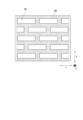
ここで、平膜状部材2k,2k+1の間に配置されて第1流路S1を形成するスペーサ3の詳細について図4を参照しつつ説明する。尚、平膜状部材2k+1,2k+2の間に配置されて第2流路S2を形成するスペーサ3も同様の形状を有しており、加湿部本体10において配置される向きのみが異なっているものとする。図4はスペーサ3を示す平面図である。尚、図1~3においては説明の都合上、貫通孔33の図示を省略しているが、実際には図4に示されたような貫通孔33が形成されているものとする。
Here, the details of the
スペーサ3は、複数の貫通孔33を有する。第1流路S1において、スペーサ3のZ方向の一方側の空間を第1空間A1とし、他方側の空間を第2空間A2とする。貫通孔33は、スペーサ3をZ方向に貫通することにより、第1空間A1と第2空間A2とを連通させる。
The
貫通孔33は、X方向及びY方向のそれぞれに平行な辺を有して長方形状(好ましくは正方形状)に形成されている。複数の貫通孔33によって、複数の貫通孔列L1~L5が形成されている。各々の貫通孔列L1~L5は、それぞれ複数の貫通孔33がY方向に並ぶことで形成されている。複数の貫通孔列L1~L5は、X方向に並んでいる。
The through holes 33 are formed in a rectangular shape (preferably a square shape) with sides parallel to the X and Y directions. A plurality of through
各々の貫通孔列L1~L5において、隣り合う2つの貫通孔の間に非貫通部34が形成されている。貫通孔列L2における非貫通部34は、隣り合う貫通孔列L1,L3の貫通孔33のY方向中央部と、X方向に隣り合うように配置されている。他の隣り合う貫通孔列同士においても貫通孔33と非貫通部34との関係は同様である。即ち、隣り合う貫通孔列における貫通孔33同士のY方向位置は、貫通孔33のY方向寸法の半分だけずれている。
In each of the through hole rows L1 to L5, a
上記のような貫通孔33及び非貫通部34の配置により、Y方向における非貫通部34の全範囲において、非貫通部34を通過するとともにX方向に延びる仮想延長線LNは、他の貫通孔列(特に隣り合う貫通孔列)における貫通孔33を通過する。非貫通部34は水分Wが移動しにくい部分であるものの、非貫通部34を横切る湿潤流体Fは、必ず貫通孔33を横切ることとなり、スペーサ3のうち端部を除くY方向全域において、いずれの位置を通過する湿潤流体Fも貫通孔33を横切る。
By arranging the through
また、X方向に隣り合う2つの貫通孔列において、一方の貫通孔列の非貫通部34の全体が、他方の貫通孔列の貫通孔33と隣り合う。また、各々の貫通孔列における貫通孔33のうち非貫通部34との境界となる端縁部331をX方向に延長すると、隣り合う貫通孔列における貫通孔33を通過する。
In two through-hole rows adjacent in the X direction, the entire
また、各貫通孔列L1~L5において、複数の貫通孔33はY方向において等間隔で配置されており、複数の貫通孔列L1~L5は、X方向において等間隔で配置されている。尚、各貫通孔列において複数の貫通孔が等間隔に配置されていなくてもよく、複数の貫通孔列同士の間隔が等間隔でなくてもよい。スペーサ3において複数の貫通孔33は、スペーサ3のX方向中央部を通過してY方向に延びる仮想線と、スペーサ3のY方向中央部を通過してX方向に延びる仮想線と、の両方に関して線対称な配置となっている。
In each of the through-hole rows L1 to L5, the multiple through
次に、上記のようなスペーサ3が設けられた第1流路S1における湿潤流体の流れの詳細について、図5を参照しつつ説明する。図5は、加湿装置1の1つの流路S1における水分の移動態様を示す断面図である。
Next, the flow of the moist fluid in the first flow path S1 in which the
まず、湿潤流体Fは、X方向に沿って第1流路S1を通過する。このとき、湿潤流体に含まれる水分Wは、湿潤流体Fの進行に伴って徐々に平膜状部材2k,2k+1に向かって近づいていく。従って、平膜状部材2k,2k+1に近い位置を通過する湿潤流体Fに含まれる水分Wは、比較的上流側において平膜状部材2k,2k+1に到達し、平膜状部材2k,2k+1から遠い位置を通過する湿潤流体Fに含まれる水分Wは、比較的下流側において平膜状部材2k,2k+1に到達する。
First, the wet fluid F passes through the first flow path S1 along the X direction. At this time, the moisture W contained in the wet fluid gradually approaches the
図5に示す断面は、一方側当接部31を通過するものである。このとき、平膜状部材2kに向かって移動する水分Wは、貫通孔33を通過することで平膜状部材2kに到達することができる。これに対し、貫通孔33が形成されていない構成では、水分Wがスペーサを通過することができず、平膜状部材2kに到達することができないため、平膜状部材2k+1に向かう必要がある(一点鎖線で図示)。即ち、貫通孔33が形成されていない構成では、水分Wの最大移動距離は、一方側当接部31から平膜状部材2k+1(又は他方側当接部32から平膜状部材2k)までの距離となる。
The cross section shown in FIG. 5 passes through the one-
一方、貫通孔33が形成されたスペーサ3を用いる場合には、水分Wの最大移動距離は、平膜状部材2k,2k+1の間隔の半分となる。従って、湿潤流体Fに含まれる全ての水分Wが平膜状部材2k,2k+1に到達するために必要な湿潤流体Fの進行距離を小さくすることができる。
On the other hand, when a
このように、本発明の実施形態に係る加湿装置1によれば、スペーサ3が貫通孔33を有していることで、第1流路S1においてスペーサ3のZ方向両側の空間A1,A2同士の間で水分の移動が容易となり、湿潤流体Fに含まれる水分Wは、2つの平膜状部材2k,2k+1のうち近い方に向かって移動することができ、水分Wが平膜状部材2k,2k+1に到達しやすく、水分交換性能を向上させることができる。
In this way, according to the
また、スペーサ3に複数の貫通孔列L1~L5が形成されていることで、スペーサ3において貫通孔33を点在するように配置することができ、スペーサ3の全体において水分を移動容易とし、水分交換性能をさらに向上させることができる。
In addition, by forming multiple through-hole rows L1 to L5 in the
また、Y方向における非貫通部34の全範囲において、非貫通部34を通過するとともにX方向に延びる仮想延長線LNが他の貫通孔列における貫通孔33を通過することで、スペーサ3のY方向全域(貫通孔33が形成されない端部は除く)に亘って水分を移動容易とし、水分交換性能をさらに向上させることができる。
In addition, over the entire range of the
また、X方向に隣り合う2つの貫通孔列において、一方の貫通孔列の非貫通部34の全体が、他方の貫通孔列の貫通孔33と隣り合うことで、非貫通部34を横切る湿潤流体Fがその前後において貫通孔33を横切ることとなり、湿潤流体Fが進行する際に水分Wが移動しにくい領域が連続することを抑制することができる。
In addition, in two through-hole rows adjacent to each other in the X direction, the entire
また、スペーサ3が波形状に形成されていることで、流体を通過しやすくすることができるとともに、広範囲に亘って平膜状部材2k,2k+1同士の間隔を維持しやすくすることができる。
In addition, the
尚、本発明は上記の実施形態に限定されず、本発明の目的が達成できる他の構成等を含み、以下に示すような変形等も本発明に含まれる。例えば、上記の本発明の実施形態では、貫通孔33が長方形状(好ましくは正方形状)であるものとしたが、貫通孔の形状は特に限定されず、図6~8に示すような変形例1~3のような形状であってもよい。
The present invention is not limited to the above embodiment, but includes other configurations that can achieve the object of the present invention, and the following modifications are also included in the present invention. For example, in the above embodiment of the present invention, the through
図6に示す変形例1では、スペーサ3には、Y方向を長辺方向とする長方形状の貫通孔35が形成されている。変形例1においても、上記の実施形態同様に貫通孔列が形成されており、貫通孔列同士の貫通孔35の位置関係は同様である。
In the first modified example shown in FIG. 6, the
図7に示す変形例2では、スペーサ3には、オーバル形状の貫通孔36が形成されている。貫通孔36は、Y方向に沿って延びる一対の辺と、一対の辺の端部同士を接続する一対の円弧状部分と、を有している。変形例2においても、上記の実施形態同様に貫通孔列が形成されており、貫通孔列同士の貫通孔36の位置関係は同様である。
In the second modification shown in FIG. 7, an oval-shaped through
図8に示す変形例3では、スペーサ3には、円状の貫通孔37が形成されている。変形例3においても、上記の実施形態同様に貫通孔列が形成されており、貫通孔列同士の貫通孔37の位置関係は同様である。
In the third modification shown in FIG. 8, a circular through
また、1つのスペーサに形成される複数の貫通孔の形状及び寸法は同一でなくてもよく、形状又は寸法が異なる複数の貫通孔が組み合わされていてもよい。また、貫通孔の形状は上記の実施形態及び変形例1~3に限定されない。 The shapes and dimensions of the multiple through holes formed in one spacer do not have to be the same, and multiple through holes with different shapes or dimensions may be combined. The shapes of the through holes are not limited to those in the above embodiment and modified examples 1 to 3.
また、上記の本発明の実施形態では、隣り合う貫通孔列において貫通孔33同士のY方向位置が貫通孔33のY方向寸法の半分だけずれているものとしたが、貫通孔の配置はこれに限定されない。例えば、X方向に隣り合う2つの貫通孔列において、一方の貫通孔列の非貫通部の全体が、他方の貫通孔列の貫通孔と隣り合っていなくてもよい。即ち、貫通孔のY方向位置が等しい2つの貫通孔列がX方向に並んでペアを形成し、この貫通孔列のペアにおける非貫通部の全体が、このペアに隣り合う他の貫通孔列の貫通孔と隣り合うような構成としてもよい。
In addition, in the above embodiment of the present invention, the Y-direction positions of the through
また、Y方向における非貫通部の所定の範囲において、非貫通部を通過するとともにX方向に延びる仮想延長線が他の貫通孔列における貫通孔を通過しなくても(即ち、非貫通部のみを通過する仮想延長線が存在しても)よい。例えば、貫通孔がX方向に沿って並んでいてもよい。湿潤流体がX方向に進行する際、湿潤流体に含まれる水分は、Z方向だけでなくY方向にも移動可能である。Y方向における所定の範囲において、X方向に延びる仮想延長線が非貫通部のみを通過し貫通孔を通過しない場合であっても、この範囲が、水分がY方向に移動可能な距離と比較して充分に小さい場合には、水分交換性能に影響を与えにくい。 In addition, in a predetermined range of the non-penetrating portion in the Y direction, a virtual extension line that passes through the non-penetrating portion and extends in the X direction may not pass through the through holes in other rows of through holes (i.e., there may be a virtual extension line that passes only through the non-penetrating portion). For example, the through holes may be aligned along the X direction. When the moistening fluid advances in the X direction, the moisture contained in the moistening fluid can move not only in the Z direction but also in the Y direction. Even if, in a predetermined range in the Y direction, a virtual extension line extending in the X direction passes only through the non-penetrating portion and does not pass through the through holes, this range is sufficiently small compared to the distance that moisture can move in the Y direction, it is unlikely to affect the moisture exchange performance.
また、上記の本発明の実施形態では、スペーサ3に複数の貫通孔列L1~L5が形成されているものとしたが、複数の貫通孔が列を形成せずに点在していたり、ランダムに配置されていたりしてもよい。また、スペーサに1つの貫通孔のみが形成されていてもよい。
In the above embodiment of the present invention, multiple rows of through holes L1 to L5 are formed in the
また、上記の本発明の実施形態では、スペーサ3が波形状に形成されているものとしたが、スペーサの形状は特に限定されず、隣り合う2つの平膜状部材のそれぞれに対して当接可能な部位を所定範囲に亘って有していればよい。例えば、スペーサは、平膜状部材と平行に延びる板状部分と、板状部分から平膜状部材に向かって突出する部分(一方側当接部及び他方側当接部)と、を有し、板状部分に貫通孔が形成される構成であってもよい。
In addition, in the above embodiment of the present invention, the
以上、本発明の実施形態について説明したが、本発明は上記の実施形態に係る燃料電池用の加湿装置に限定されるものではなく、本発明の概念及び特許請求の範囲に含まれるあらゆる態様を含む。また、上述した課題及び効果の少なくとも一部を奏するように、各構成を適宜選択的に組み合わせてもよい。例えば、上記実施形態における、各構成要素の形状、材料、配置、サイズ等は、本発明の具体的使用態様によって適宜変更され得る。 Although the embodiments of the present invention have been described above, the present invention is not limited to the humidifier for fuel cells according to the above-mentioned embodiments, but includes all aspects included in the concept of the present invention and the scope of the claims. In addition, each configuration may be appropriately and selectively combined to achieve at least some of the above-mentioned problems and effects. For example, the shape, material, arrangement, size, etc. of each component in the above-mentioned embodiments may be appropriately changed depending on the specific usage mode of the present invention.
1…加湿装置、2k…平膜状部材、3…スペーサ、31…一方側当接部、32…他方側当接部、33…貫通孔、34…非貫通部、S1…第1流路、S2…第2流路、A1…第1空間、A2…第2空間、L1~L5…貫通孔列、LN…仮想延長線 1...humidifier, 2k...flat membrane member, 3...spacer, 31...contact part on one side, 32...contact part on the other side, 33...through hole, 34...non-through part, S1...first flow path, S2...second flow path, A1...first space, A2...second space, L1-L5...through hole row, LN...imaginary extension line
Claims (5)
隣り合う2つの前記平膜状部材同士の間に設けられることで流体の流路を形成するスペーサと、を備え、
前記スペーサは、2つの前記平膜状部材のうち一方に当接する一方側当接部と、他方に当接する他方側当接部と、前記複数の平膜状部材の積層方向において当該スペーサの両側の空間を連通させる貫通孔と、を有することを特徴とする、燃料電池用の加湿装置。 A plurality of laminated flat membrane members that are moisture permeable;
a spacer that is provided between two adjacent flat membrane members to form a fluid flow path;
A humidifier for a fuel cell, characterized in that the spacer has a one-side abutment portion that abuts one of the two flat membrane members, an other-side abutment portion that abuts the other, and a through hole that connects the spaces on both sides of the spacer in the stacking direction of the multiple flat membrane members.
前記貫通孔列において、隣り合う2つの前記貫通孔の間に非貫通部が形成され、
前記配列方向における前記非貫通部の全範囲において、前記非貫通部を通過するとともに前記直交方向に延びる仮想延長線は、少なくとも1つの他の前記貫通孔列において前記貫通孔を通過することを特徴とする、請求項2に記載の燃料電池用の加湿装置。 The orthogonal direction is a fluid passage direction,
In the through hole row, a non-through portion is formed between two adjacent through holes,
3. A humidifier for a fuel cell as described in claim 2, characterized in that, throughout the entire range of the non-penetrating portion in the arrangement direction, a virtual extension line that passes through the non-penetrating portion and extends in the perpendicular direction passes through the through holes in at least one other row of through holes.
Priority Applications (2)
| Application Number | Priority Date | Filing Date | Title |
|---|---|---|---|
| JP2022152706A JP2024073670A (en) | 2022-09-26 | 2022-09-26 | Humidification device for fuel cell |
| PCT/EP2023/075672 WO2024068341A1 (en) | 2022-09-26 | 2023-09-18 | Humidifying device for a fuel cell having a special spacer |
Applications Claiming Priority (1)
| Application Number | Priority Date | Filing Date | Title |
|---|---|---|---|
| JP2022152706A JP2024073670A (en) | 2022-09-26 | 2022-09-26 | Humidification device for fuel cell |
Publications (1)
| Publication Number | Publication Date |
|---|---|
| JP2024073670A true JP2024073670A (en) | 2024-05-30 |
Family
ID=88147107
Family Applications (1)
| Application Number | Title | Priority Date | Filing Date |
|---|---|---|---|
| JP2022152706A Pending JP2024073670A (en) | 2022-09-26 | 2022-09-26 | Humidification device for fuel cell |
Country Status (2)
| Country | Link |
|---|---|
| JP (1) | JP2024073670A (en) |
| WO (1) | WO2024068341A1 (en) |
Family Cites Families (4)
| Publication number | Priority date | Publication date | Assignee | Title |
|---|---|---|---|---|
| US6145588A (en) | 1998-08-03 | 2000-11-14 | Xetex, Inc. | Air-to-air heat and moisture exchanger incorporating a composite material for separating moisture from air technical field |
| JP2005317322A (en) * | 2004-04-28 | 2005-11-10 | Equos Research Co Ltd | Separator and fuel cell using the same |
| US20140306359A1 (en) * | 2013-04-15 | 2014-10-16 | GM Global Technology Operations LLC | Simplified Fuel Cell Humidifier Design |
| CA3007452C (en) * | 2015-12-18 | 2018-10-23 | Core Energy Recovery Solutions Inc. | Enthalpy exchanger |
-
2022
- 2022-09-26 JP JP2022152706A patent/JP2024073670A/en active Pending
-
2023
- 2023-09-18 WO PCT/EP2023/075672 patent/WO2024068341A1/en not_active Ceased
Also Published As
| Publication number | Publication date |
|---|---|
| WO2024068341A1 (en) | 2024-04-04 |
Similar Documents
| Publication | Publication Date | Title |
|---|---|---|
| EP2851642B1 (en) | Heat-exchange element and air conditioner | |
| KR890003897B1 (en) | heat transmitter | |
| JP6790321B2 (en) | Humidifier fluid plate | |
| CN101266109A (en) | Total heat exchanger and manufacturing method thereof | |
| CN117836050A (en) | Humidifier with channel plate, channel section plate for humidifier and channel plate | |
| JP5817652B2 (en) | Total heat exchange element | |
| CN113748306B (en) | Total heat exchange element | |
| JP2022080281A (en) | Lamination unit for humidifier | |
| JP2024073670A (en) | Humidification device for fuel cell | |
| JP7392314B2 (en) | humidifier | |
| CN115295833B (en) | A cross-flow flat membrane humidifier | |
| CN112303775A (en) | Plate-type gas humidifier | |
| JPH09280765A (en) | Heat-exchange element | |
| KR20100059140A (en) | Heat exchange element for ventilating duct | |
| JP4326851B2 (en) | Humidification element, antibacterial humidification element, humidifier and ventilator | |
| JP5781221B2 (en) | Heat exchange element and air conditioner | |
| JP5790600B2 (en) | Heat exchange element | |
| KR100540242B1 (en) | heat transmitter | |
| JP2006071149A (en) | Heat exchange element | |
| JP2006071150A (en) | Heat exchange element | |
| JP3156162U (en) | Total heat exchange element | |
| EP3954962A1 (en) | Method for using sheet-shaped member | |
| JP2025089943A (en) | fuel cell humidifier | |
| JP2007017108A (en) | humidifier | |
| JPH03286996A (en) | Heat exchanger |