JP2024067254A - furniture - Google Patents

furniture Download PDF

Info

Publication number
JP2024067254A
JP2024067254A JP2022177178A JP2022177178A JP2024067254A JP 2024067254 A JP2024067254 A JP 2024067254A JP 2022177178 A JP2022177178 A JP 2022177178A JP 2022177178 A JP2022177178 A JP 2022177178A JP 2024067254 A JP2024067254 A JP 2024067254A
Authority
JP
Japan
Prior art keywords
edge
edge portion
installation surface
connecting member
functional
Prior art date
Legal status (The legal status is an assumption and is not a legal conclusion. Google has not performed a legal analysis and makes no representation as to the accuracy of the status listed.)
Pending
Application number
JP2022177178A
Other languages
Japanese (ja)
Inventor
慎太郎 門田
Shintaro Kadota
拓郎 産田
Takuro Ubuta
Current Assignee (The listed assignees may be inaccurate. Google has not performed a legal analysis and makes no representation or warranty as to the accuracy of the list.)
Okamura Corp
Original Assignee
Okamura Corp
Priority date (The priority date is an assumption and is not a legal conclusion. Google has not performed a legal analysis and makes no representation as to the accuracy of the date listed.)
Filing date
Publication date
Application filed by Okamura Corp filed Critical Okamura Corp
Priority to JP2022177178A priority Critical patent/JP2024067254A/en
Publication of JP2024067254A publication Critical patent/JP2024067254A/en
Pending legal-status Critical Current

Links

Images

Landscapes

  • Tables And Desks Characterized By Structural Shape (AREA)
  • Chairs Characterized By Structure (AREA)

Abstract

To provide furniture capable of preventing dust and the like adhering to a part arranged along an installation surface before the posture is changed from adhering to a user when a posture is changed in the furniture which can be installed in different postures with respect to the installation surface, and whose height of the functional part can be changed.SOLUTION: A support structure 2 includes a first edge part 41 extending in a predetermined direction, a second edge part 42 extending in a direction intersecting with the direction that the first edge part 41 extends, a first fixed part, and a second fixed part. The furniture can be installed either in a first posture in which the first edge part 41 is arranged along an installation surface 11, and at least a part of the first edge part 41 touches the installation surface 11 or in a second posture in which the second edge part 42 is arranged along the installation surface 11 and at least a part of the second edge part 42 touches the installation surface 11. A height dimension of a functional part 3 fixed to the first fixed part from the installation surface 11 in the first posture, and a height dimension of the functional part 3 fixed to the second fixed part from the installation surface 11 in the second posture are set for different values.SELECTED DRAWING: Figure 1

Description

本発明は、什器に関する。 The present invention relates to fixtures.

設置面からの座の高さを変更できる椅子として、例えば、設置面に接地し座を支持する支持構造体に上下方向の中央とずれた位置に座を設け、上下反転させて設置面に接地した状態でも座に着座可能な椅子が知られている(例えば、特許文献1参照)。このような椅子は、上下反転させることで設置面からの座の高さを変えることができる。 As an example of a chair that allows the seat height from the surface on which it is placed to be changed, there is a chair that has a seat that is offset from the vertical center on a support structure that touches the surface and supports the seat, and that allows the user to sit on the seat even when the chair is turned upside down and placed on the surface on which it is placed (see, for example, Patent Document 1). With such a chair, the seat height from the surface on which it is placed can be changed by turning it upside down.

実公昭48-017139号公報Japanese Utility Model Publication No. 48-017139

しかしながら、特許文献1に開示された椅子は、上下反転させると、上下反転させる前に設置面に接地していた支持構造体の下端が、支持構造体の上端に配置される。このため、上下反転させる前に設置面に接地していた支持構造体の下端に設置面の埃などが付着していると、上下反転させた後の支持構造体の上端に埃などが付着している状態となる。支持構造体の上端は、椅子の肘掛けや背もたれになることが想定されるため、椅子の使用者が支持構造体の上端に接触して衣服や手などに埃などが付着する虞がある。 However, when the chair disclosed in Patent Document 1 is turned upside down, the lower end of the support structure that was in contact with the installation surface before the chair was turned upside down is positioned at the upper end of the support structure. Therefore, if dust or the like from the installation surface is attached to the lower end of the support structure that was in contact with the installation surface before the chair was turned upside down, the dust or the like will be attached to the upper end of the support structure after the chair is turned upside down. Since the upper end of the support structure is expected to become the armrests and backrest of the chair, there is a risk that the user of the chair will come into contact with the upper end of the support structure and that dust or the like will adhere to their clothes, hands, etc.

そこで、本発明は、設置面に対して異なる姿勢に設置し、椅子の座などの機能部の高さを変更可能な什器において、姿勢を変えた際に、姿勢を変える前に設置面に沿って配置されていた部分に付着した埃などが使用者に付着することを防止できる什器を提供することを目的とする。 The present invention aims to provide a piece of furniture that can be installed in different positions relative to the installation surface and has adjustable heights for functional parts such as chair seats, and that can prevent dust and other particles that have adhered to parts that were aligned along the installation surface before the position was changed from adhering to the user when the position is changed.

上記目的を達成するため、本発明に係る什器は、設置面に設置される支持構造体と、前記支持構造体に着脱可能に固定される機能部と、を有し、前記支持構造体は、所定の方向に延びる第1縁部と、前記第1縁部が延びる方向と交差する方向に延びる第2縁部と、前記機能部を着脱可能な第1固定部と、前記第1固定部と異なる位置に設けられ前記機能部を着脱可能な第2固定部と、を有し、前記第1縁部が前記設置面に沿って配置され、前記第1縁部の少なくとも一部が前記設置面に接地した第1姿勢、および前記第2縁部が前記設置面に沿って配置され、前記第2縁部の少なくとも一部が前記設置面に接地した第2姿勢のいずれの姿勢でも設置可能であり、前記機能部は、前記第1姿勢では前記第1固定部に固定され、前記第2姿勢では前記第2固定部に固定され、前記第1姿勢において前記第1固定部に固定された前記機能部の前記設置面からの高さ寸法と、前記第2姿勢において前記第2固定部に固定された前記機能部の前記設置面からの高さ寸法と、は異なる値に設定されている。 In order to achieve the above object, the fixture of the present invention has a support structure to be installed on an installation surface and a functional part detachably fixed to the support structure, the support structure having a first edge extending in a predetermined direction, a second edge extending in a direction intersecting the direction in which the first edge extends, a first fixing part to which the functional part can be detached, and a second fixing part provided at a position different from the first fixing part to which the functional part can be detached, and can be installed in either of a first posture in which the first edge is arranged along the installation surface and at least a portion of the first edge is in contact with the installation surface, and a second posture in which the second edge is arranged along the installation surface and at least a portion of the second edge is in contact with the installation surface, the functional part is fixed to the first fixing part in the first posture and fixed to the second fixing part in the second posture, and the height dimension from the installation surface of the functional part fixed to the first fixing part in the first posture and the height dimension from the installation surface of the functional part fixed to the second fixing part in the second posture are set to different values.

第1姿勢において第1固定部に固定された機能部の設置面からの高さ寸法と、第2姿勢において第2固定部に固定された機能部の設置面からの高さ寸法と、は異なる値に設定されている。これにより、什器を設置面に対して異なる姿勢に設置することによって、椅子の座などの機能部の高さを変更できる。
支持構造体の第1縁部と第2縁部とは、互いに交差する方向に延びている。これにより、第1姿勢で第1縁部が設置面に沿って配置される場合は、第2縁部は、設置面に交差する方向に延びるため、支持構造体の上縁部に沿って上方を向くように配置されることがなく、使用者が接触しにくい位置に配置される。また、第2姿勢で第2縁部が設置面に沿って配置される場合は、第1縁部は、設置面に交差する方向に延びるため、支持構造体の上縁部に沿って上方を向くように配置されることがなく、使用者が接触しにくい位置に配置される。このため、什器の姿勢を第1姿勢から第2姿勢に変更する場合に、変更前に設置面に沿って配置され少なくとも一部が設置面に接地していた第1縁部に設置面の埃などが付着していても、その埃などが使用者に付着することを防止できる。同様に、什器の姿勢を第2姿勢から第1姿勢に変更する場合に、変更前に設置面に沿って配置され少なくとも一部が設置面に接地していた第2縁部に設置面の埃などが付着していても、その埃などが使用者に付着することを防止できる。
The height dimension from the installation surface of the functional part fixed to the first fixing part in the first position and the height dimension from the installation surface of the functional part fixed to the second fixing part in the second position are set to different values. This makes it possible to change the height of the functional part, such as a chair seat, by installing the fixture in a different position relative to the installation surface.
The first edge and the second edge of the support structure extend in directions intersecting each other. As a result, when the first edge is disposed along the installation surface in the first position, the second edge extends in a direction intersecting the installation surface, and is not disposed to face upward along the upper edge of the support structure, and is disposed in a position where it is difficult for the user to contact. Also, when the second edge is disposed along the installation surface in the second position, the first edge extends in a direction intersecting the installation surface, and is not disposed to face upward along the upper edge of the support structure, and is disposed in a position where it is difficult for the user to contact. Therefore, when the position of the fixture is changed from the first position to the second position, even if dust or the like from the installation surface is attached to the first edge that is disposed along the installation surface and at least a part of which is in contact with the installation surface before the change, the dust or the like can be prevented from adhering to the user. Similarly, when the position of the fixture is changed from the second position to the first position, even if dust or the like from the installation surface is attached to the second edge that is disposed along the installation surface and at least a part of which is in contact with the installation surface before the change, the dust or the like can be prevented from adhering to the user.

本発明に係る什器では、前記第1縁部および前記第2縁部の少なくとも一方の縁部は、前記縁部が延びる方向に延びる本体部と、前記本体部から前記縁部が延びる方向に交差する方向に突出する突出部と、を有し、前記縁部が前記設置面に沿って配置されると、前記突出部が前記設置面に接地し、前記本体部が前記設置面の上方に間隔をあけて配置されてもよい。 In the fixture of the present invention, at least one of the first and second edges has a main body extending in the direction in which the edge extends and a protruding portion protruding from the main body in a direction intersecting the direction in which the edge extends, and when the edge is arranged along the installation surface, the protruding portion may come into contact with the installation surface and the main body may be arranged above the installation surface with a gap therebetween.

このような構成とすることにより、第1縁部および第2縁部の少なくとも一方の縁部は、突出部のみが設置面と接地するため、設置面に沿って配置された際に埃などが付着する部分を主に突出部にして、本体部には埃などが付着しにくい構成にできる。これにより、什器の姿勢を変更する場合に、変更前に設置面に沿って配置されていた縁部に付着していた埃などが使用者に付着することを更に防止できる。使用者に対しても、埃などが付着している部分(突出部)を明確にできる。 With this configuration, only the protruding portion of at least one of the first and second edges comes into contact with the installation surface, so that the portion to which dust and other particles adhere when the fixture is placed along the installation surface is mainly the protruding portion, and dust and other particles are less likely to adhere to the main body. This makes it possible to further prevent dust and other particles that were attached to the edge that was placed along the installation surface before the change from adhering to the user when the fixture's position is changed. The portion to which dust and other particles adhere (the protruding portion) can also be made clear to the user.

本発明に係る什器では、前記突出部は、前記本体部とは別の部材であり、前記本体部に固定されていてもよい。 In the fixture of the present invention, the protrusion may be a separate member from the main body and may be fixed to the main body.

このような構成とすることにより、突出部を設けるために本体部に加工を施す必要が無く、本体部および突出部を有する縁部を容易にかつ安価に製作できる。突出部を本体部から取り外し可能な部材とすれば、設置面との接触によって汚れたり損傷したりした場合に突出部を交換できる。 By configuring it in this way, there is no need to process the main body to provide the protrusion, and the main body and the edge having the protrusion can be manufactured easily and inexpensively. If the protrusion is a member that can be removed from the main body, it can be replaced if it becomes dirty or damaged due to contact with the installation surface.

本発明に係る什器では、前記第1縁部と前記第2縁部とは、接続されていてもよい。 In the fixture of the present invention, the first edge and the second edge may be connected.

このような構成とすることにより、第1縁部および第2縁部のうちの設置面に沿って配置されていない縁部は、設置面から上方に延びる縁部になる。これにより、設置面に沿って配置されていない縁部は、使用者が接触しにくい位置に配置される。このため、什器の姿勢を第1姿勢から第2姿勢、または第2姿勢から第1姿勢に変更する場合に、変更前に設置面に沿って配置されていた縁部に設置面の埃などが付着していても、その埃などが使用者に付着することを防止できる。 With this configuration, the edge of the first edge and the second edge that is not positioned along the installation surface becomes an edge that extends upward from the installation surface. As a result, the edge that is not positioned along the installation surface is positioned in a position that is difficult for the user to contact. Therefore, when changing the position of the fixture from the first position to the second position, or from the second position to the first position, even if dust from the installation surface is attached to the edge that was positioned along the installation surface before the change, the dust can be prevented from adhering to the user.

本発明に係る什器では、前記機能部は、前記第1固定部および前記第2固定部の少なくとも一方の固定部に固定可能な固定部材を有し、前記固定部は、所定の方向に延びる棒状に形成され、前記固定部材は、前記固定部が延びる方向に交差する方向から嵌めこまれる凹部を有していてもよい。 In the fixture of the present invention, the functional part has a fixing member that can be fixed to at least one of the first fixing part and the second fixing part, the fixing part is formed in a rod shape extending in a predetermined direction, and the fixing member may have a recess that is fitted from a direction intersecting the direction in which the fixing part extends.

このような構成とすることにより、支持構造体の固定部に機能部の固定部材を嵌めこむことで機能部を支持構造体に容易に固定できる。 With this configuration, the functional part can be easily fixed to the support structure by fitting the fixing member of the functional part into the fixing part of the support structure.

本発明に係る什器では、前記支持構造体は、幅方向に互いに間隔をあけて設けられ、それぞれ前記第1縁部および前記第2縁部を有する枠状の一対の枠状部材と、前記一対の枠状部材それぞれの前記第1縁部における前記第1縁部が延びる方向の中間部の間に架設された第1連結材と、前記一対の枠状部材それぞれの前記第2縁部における前記第2縁部が延びる方向の中間部の間に架設された第2連結材と、を有し、前記第1連結材には、前記第2固定部が設けられ、前記第2連結材には、前記第1固定部が設けられていてもよい。 In the fixture of the present invention, the support structure includes a pair of frame-shaped members spaced apart from each other in the width direction, each of which has the first edge and the second edge, a first connecting member installed between the middle parts of the first edge parts of the pair of frame-shaped members in the direction in which the first edge parts extend, and a second connecting member installed between the middle parts of the second edge parts of the pair of frame-shaped members in the direction in which the second edge parts extend, and the first connecting member may be provided with the second fixing part, and the second connecting member may be provided with the first fixing part.

このような構成とすることにより、一対の枠状部材の間の第1連結材および第2連結材に機能部が固定される。このため、一対の枠状部材を幅方向の両側から把持することで、什器を容易に持ち運ぶことができる。
機能部が第1縁部における第1縁部が延びる方向の中間部の位置、または第2縁部における第2縁部が延びる方向の中間部の位置に固定されることにより、枠状部材の少なくとも一部は、機能部よりも第1縁部が延びる方向および第2縁部が延びる方向の少なくとも一方に突出する。これにより、枠状部材を把持する際に機能部と干渉せず、把持しやすい。
什器が椅子であり、機能部に使用者が着座可能な座が設けられる場合には、座(機能部)の幅方向の両側に配置される枠状部材における機能部よりも第1縁部が延びる方向および第2縁部が延びる方向の少なくとも一方に突出する部分を肘掛けとして使用できる。
With this configuration, the functional portion is fixed to the first connecting member and the second connecting member between the pair of frame-shaped members, so that the fixture can be easily carried by grasping the pair of frame-shaped members from both sides in the width direction.
By fixing the functional part to a position of a middle part of the first edge part in the extending direction of the first edge part or a position of a middle part of the second edge part in the extending direction of the second edge part, at least a part of the frame-shaped member protrudes beyond the functional part in at least one of the extending directions of the first edge part and the extending direction of the second edge part, thereby making it easy to grip the frame-shaped member without interfering with the functional part when gripping it.
When the furniture is a chair and the functional part is provided with a seat on which a user can sit, the parts of the frame-shaped members arranged on both sides of the width of the seat (functional part) that protrude further than the functional part in at least one of the directions in which the first edge portion extends and the second edge portion extends can be used as armrests.

本発明に係る什器では、前記支持構造体は、幅方向に互いに間隔をあけて設けられた矩形枠状の一対の枠状部材を有し、前記枠状部材は、前記第1縁部および前記第2縁部と、前記第1縁部と同じ長さであり前記第1縁部と同じ方向に延びて前記第1縁部と前記第2縁部が延びる方向に間隔をあけて対向して配置された第3縁部と、前記第2縁部と同じ長さであり前記第2縁部と同じ方向に延びて前記第2縁部と前記第1縁部が延びる方向に間隔をあけて対向して配置された第4縁部と、を有し、前記第3縁部には、前記第1固定部が設けられ、前記第4縁部には、前記第2固定部が設けられていてもよい。 In the fixture of the present invention, the support structure has a pair of rectangular frame members spaced apart from each other in the width direction, and the frame members have the first edge portion and the second edge portion, a third edge portion that is the same length as the first edge portion and extends in the same direction as the first edge portion and is arranged opposite to the first edge portion and is spaced apart in the direction in which the first edge portion and the second edge portion extend, and a fourth edge portion that is the same length as the second edge portion and extends in the same direction as the second edge portion and is arranged opposite to the second edge portion and is spaced apart in the direction in which the second edge portion and the first edge portion extend, and the third edge portion may be provided with the first fixing portion, and the fourth edge portion may be provided with the second fixing portion.

このような構成とすることにより、一対の枠状部材に第1縁部、第2縁部とともに第1固定部および第2固定部を設けることができるため、支持構造体を簡便な構造にできる。 By configuring in this way, a pair of frame-shaped members can be provided with a first edge portion, a second edge portion, a first fixing portion, and a second fixing portion, making it possible to simplify the structure of the support structure.

本発明に係る什器では、前記第1縁部が延びる方向と前記第2縁部が延びる方向とは直交し、前記第1縁部と前記第3縁部との前記第2縁部が延びる方向の間隔と、前記第2縁部と前記第4縁部との前記第1縁部が延びる方向の間隔と、は、異なる値に設定されていてもよい。 In the fixture of the present invention, the direction in which the first edge portion extends and the direction in which the second edge portion extends may be perpendicular to each other, and the distance between the first edge portion and the third edge portion in the direction in which the second edge portion extends and the distance between the second edge portion and the fourth edge portion in the direction in which the first edge portion extends may be set to different values.

このような構成とすることにより、簡便な構成で第1姿勢の機能部の高さと、第2姿勢の機能部の高さとを異なる値に設定できる。 By configuring in this way, the height of the functional part in the first position and the height of the functional part in the second position can be set to different values with a simple configuration.

本発明によれば、設置面に対して異なる姿勢に設置可能な什器において、姿勢を変えた際に、姿勢を変える前に設置面に沿って配置されていた部分に付着した埃などが使用者に付着することを防止できる。 According to the present invention, in a fixture that can be installed in different positions relative to the installation surface, when the position is changed, dust and other particles that were attached to the part that was placed along the installation surface before the position was changed can be prevented from being attached to the user.

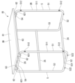
第1実施形態の第1姿勢の什器の斜視図である。FIG. 2 is a perspective view of a fixture in a first position according to the first embodiment. 第1実施形態の第1姿勢の什器の側面図である。FIG. 2 is a side view of the fixture in the first position of the first embodiment. 第1実施形態の第2姿勢の什器の斜視図である。1 is a perspective view of a fixture in a second position of the first embodiment. FIG. 第1実施形態の第2姿勢の什器の側面図である。A side view of the fixture in the second position of the first embodiment. 第1実施形態の第1姿勢の什器の座部材および背凭れ部材を省略した斜視図である。This is an oblique view of the furniture in the first position of the first embodiment, with the seat member and backrest member omitted. 第1実施形態の第2姿勢の什器の座部材および背凭れ部材を省略した斜視図である。This is an oblique view of the furniture in the second position of the first embodiment, with the seat member and backrest member omitted. 第1実施形態の第1姿勢の支持構造体の斜視図である。FIG. 2 is a perspective view of a support structure in a first position according to the first embodiment. 第1実施形態の第2姿勢の支持構造体の斜視図である。FIG. 4 is a perspective view of the support structure in a second position according to the first embodiment. 第1実施形態の機能部の斜め前方から見た斜視図である。FIG. 2 is a perspective view of the functional section of the first embodiment, as viewed obliquely from the front. 第1実施形態の機能部の斜め後ろ方から見た斜視図である。FIG. 2 is a perspective view of the functional section of the first embodiment, seen obliquely from behind; 第1固定部材の分解斜視図である。FIG. 4 is an exploded perspective view of a first fixing member. 第1姿勢の支持構造体と機能部との固定を示す斜視図である。11 is a perspective view showing the fixing of a support structure in a first position and a functional portion; FIG. 第2固定部材の斜視図である。FIG. 4 is a perspective view of a second fixing member. 第2姿勢の支持構造体と機能部との固定を示す斜視図である。13 is a perspective view showing the fixing of the support structure and the functional portion in a second attitude. FIG. 第2姿勢の支持構造体に対する機能部の取り付け方を説明する図である。13A to 13C are diagrams illustrating how to attach the functional part to the support structure in the second position. 第2姿勢の支持構造体からの機能部の外れ防止を説明する図である。11A and 11B are diagrams illustrating prevention of the functional part from coming off the support structure in the second posture. 第2実施形態の第1姿勢の什器の斜視図である。13 is a perspective view of a fixture in a first position according to a second embodiment. FIG. 第2実施形態の第1姿勢の什器の側面図である。A side view of the fixture in the first position of the second embodiment. 第2実施形態の第2姿勢の什器の斜視図である。An oblique view of the fixture in the second position of the second embodiment. 第2実施形態の第2姿勢の什器の側面図である。A side view of the fixture in the second position of the second embodiment. 第2実施形態の第1姿勢の支持構造体の斜視図である。FIG. 11 is a perspective view of a support structure in a first position according to a second embodiment. 第2実施形態の第2姿勢の支持構造体の斜視図である。FIG. 11 is a perspective view of a support structure in a second position according to the second embodiment. 機能部を斜め下方から見た斜視図である。FIG. 2 is a perspective view of the functional unit as seen obliquely from below.

(第1実施形態)
以下、本発明の実施形態による什器について、図1から図16に基づいて説明する。
図1に示すように、第1実施形態による什器1Aは、床面などの設置面11に接地して設けられる椅子である。什器1Aは、異なる2つの姿勢で設置面11に設置可能である。什器1Aは、いずれの姿勢においても使用者が着座可能である。異なる2つの姿勢のうちの一方を第1姿勢と表記し、他方を第2姿勢と表記する。図1および図2に第1姿勢の什器1Aを示す。図3および図4に第2姿勢の什器1Aを示す。
以下の什器1Aの説明において、着座した使用者の前方および後方を結ぶ水平方向を前後方向と表記し、着座した使用者の前方を「前」と表記し、後方を「後」と表記する。前後方向に直交する水平方向を幅方向と表記する。
First Embodiment
Hereinafter, a fixture according to an embodiment of the present invention will be described with reference to Figs.
As shown in Fig. 1, the furniture 1A according to the first embodiment is a chair that is placed on an installation surface 11 such as a floor. The furniture 1A can be installed on the installation surface 11 in two different positions. A user can sit on the furniture 1A in either position. One of the two different positions is referred to as a first position, and the other is referred to as a second position. Figs. 1 and 2 show the furniture 1A in the first position. Figs. 3 and 4 show the furniture 1A in the second position.
In the following description of the fixture 1A, the horizontal direction connecting the front and back of a seated user is referred to as the front-to-rear direction, the front of the seated user is referred to as the "front," and the back is referred to as the "rear." The horizontal direction perpendicular to the front-to-rear direction is referred to as the width direction.

図1から図4に示すように、什器1Aは、支持構造体2と、機能部3と、を有する。支持構造体2は、設置面11に接地して設けられる。機能部3は、使用者が着座可能な機能を有する。機能部3は、使用者が着座する座38と、着座した使用者が背を凭れかける背凭れ39と、を有する。 As shown in Figures 1 to 4, the fixture 1A has a support structure 2 and a functional unit 3. The support structure 2 is placed in contact with the installation surface 11. The functional unit 3 has a function that allows a user to sit on it. The functional unit 3 has a seat 38 on which the user sits and a backrest 39 on which the seated user leans back.

図5および図6では、座38の座部材381および背凭れ39の背凭れ部材391を省略している。図5から図8に示すように、支持構造体2は、一対の枠状部材4,4と、第1連結材21と、第2連結材22と、第3連結材23と、を有する。一対の枠状部材4,4は、第1姿勢および第2姿勢のいずれの場合も、一方が支持構造体2の幅方向の一方側の端部に設けられ、他方が支持構造体2の幅方向の他方側の端部に設けられている。一対の枠状部材4,4の形状は、互いに幅方向に対称である。第1連結材21、第2連結材22および第3連結材23は、それぞれ一対の枠状部材4,4の間に架設されている。第1連結材21、第2連結材22および第3連結材23は、棒状であり、第1姿勢および第2姿勢のいずれの場合も幅方向に延びている。本実施形態の一対の枠状部材4,4、第1連結材21、第2連結材22および第3連結材23は、鋼製のパイプを加工して形成されている。 5 and 6, the seat member 381 of the seat 38 and the backrest member 391 of the backrest 39 are omitted. As shown in Figs. 5 to 8, the support structure 2 has a pair of frame members 4, 4, a first connecting member 21, a second connecting member 22, and a third connecting member 23. In both the first and second positions, one of the pair of frame members 4, 4 is provided at one end of the support structure 2 in the width direction, and the other is provided at the other end of the support structure 2 in the width direction. The shapes of the pair of frame members 4, 4 are symmetrical to each other in the width direction. The first connecting member 21, the second connecting member 22, and the third connecting member 23 are each installed between the pair of frame members 4, 4. The first connecting member 21, the second connecting member 22, and the third connecting member 23 are rod-shaped and extend in the width direction in both the first and second positions. In this embodiment, the pair of frame members 4, 4, the first connecting member 21, the second connecting member 22, and the third connecting member 23 are formed by processing steel pipes.

枠状部材4は、幅方向から見た外形が略台形の矩形枠状である。枠状部材4における略台形の4つの辺に沿った部分を、それぞれ第1縁部41、第2縁部42、第3縁部43、第4縁部44と表記する。第1縁部41、第2縁部42、第3縁部43、第4縁部44の順に台形を描くように配置されている。第1縁部41および第3縁部43は、それぞれ直線状に延び、間隔をあけて平行に配置されている。第1縁部41は、第3縁部43よりも長い。第4縁部44は、第1縁部41および第3縁部43に対して直交する直線方向に延びている。第2縁部42は、第1縁部41とは鋭角を成し、第3縁部43とは鈍角を成すように端部同士が接続されている。第2縁部42は、長さ方向の中央部が枠状部材4の外周に張り出すように湾曲している。
本実施形態では、第1縁部41と第2縁部42とは、80°程度の角度で交差している。
以下では、各縁部が延びる方向を長さ方向、長手方向と表記することがある。
The frame member 4 has a rectangular frame shape with an outer shape of a substantially trapezoid when viewed from the width direction. The portions along the four sides of the substantially trapezoid in the frame member 4 are respectively written as a first edge portion 41, a second edge portion 42, a third edge portion 43, and a fourth edge portion 44. The first edge portion 41, the second edge portion 42, the third edge portion 43, and the fourth edge portion 44 are arranged in this order to draw a trapezoid. The first edge portion 41 and the third edge portion 43 each extend in a straight line and are arranged in parallel with a gap. The first edge portion 41 is longer than the third edge portion 43. The fourth edge portion 44 extends in a straight line direction perpendicular to the first edge portion 41 and the third edge portion 43. The second edge portion 42 has its ends connected to each other so as to form an acute angle with the first edge portion 41 and an obtuse angle with the third edge portion 43. The second edge portion 42 is curved so that the center portion in the length direction protrudes to the outer periphery of the frame member 4.
In this embodiment, the first edge 41 and the second edge 42 intersect at an angle of approximately 80°.
Hereinafter, the direction in which each edge extends may be referred to as the length direction or longitudinal direction.

第1連結材21の両端部は、一対の枠状部材4それぞれの第1縁部41の長さ方向の中間部と接合されている。第2連結材22の両端部は、一対の枠状部材4それぞれの第2縁部42の長さ方向の中間部に接合されている。第3連結材23の両端部は、一対の枠状部材4それぞれの第4縁部44の長さ方向の中間部と接合されている。 The two ends of the first connecting member 21 are joined to the middle of the length of the first edge 41 of each of the pair of frame members 4. The two ends of the second connecting member 22 are joined to the middle of the length of the second edge 42 of each of the pair of frame members 4. The two ends of the third connecting member 23 are joined to the middle of the length of the fourth edge 44 of each of the pair of frame members 4.

第1縁部41は、第1縁部41の長さ方向に延びる棒状の本体部411と、本体部411の外周に取り付けられ、本体部411の外周から径方向外側に突出する突出部412と、を有する。本体部411と突出部412とは別部材であり、突出部412が本体部411の外周に取り付けられている。突出部412は、一対の枠状部材4それぞれの本体部411の長さ方向の両端部近傍それぞれに取り付けられている。
本体部411は、上述している第1縁部41の鋼製のパイプなどである。
突出部412は、例えば、本体部411を囲繞する筒状の部材であってもよい。突出部412は、例えば、ゴムなどで形成されて弾性変形可能であり、外周に本体部411を嵌めこむためのスリットが設けられている。
The first edge portion 41 has a rod-shaped main body portion 411 extending in the length direction of the first edge portion 41, and a protrusion portion 412 attached to the outer periphery of the main body portion 411 and protruding radially outward from the outer periphery of the main body portion 411. The main body portion 411 and the protrusion portion 412 are separate members, and the protrusion portion 412 is attached to the outer periphery of the main body portion 411. The protrusion portion 412 is attached near both ends in the length direction of the main body portion 411 of each of the pair of frame-shaped members 4.
The main body 411 is the steel pipe of the first edge portion 41 described above, or the like.
The protruding portion 412 may be, for example, a cylindrical member surrounding the main body portion 411. The protruding portion 412 is formed, for example, from rubber or the like and is elastically deformable, and has a slit on its outer periphery into which the main body portion 411 is fitted.

第3連結材23は、第3連結材23の長さ方向に延びる棒状の本体部231と、本体部231の外周に取り付けられ、本体部231の外周から径方向外側に突出する突出部232と、を有する。本体部231と突出部232とは別部材であり、突出部232が本体部231の外周に取り付けられている。突出部232は、本体部231の長さ方向の中間部に間隔をあけて2つ取り付けられている。
本体部231は、上述している第3連結材23の鋼製のパイプなどである。
突出部232は、例えば、本体部231を囲繞する筒状の部材であってもよい。突出部232は、例えば、ゴムなどで形成されて弾性変形可能であり、外周に本体部231を嵌めこむためのスリットが設けられている。
The third connecting member 23 has a rod-shaped main body 231 extending in the longitudinal direction of the third connecting member 23, and a protruding portion 232 attached to the outer periphery of the main body 231 and protruding radially outward from the outer periphery of the main body 231. The main body 231 and the protruding portion 232 are separate members, and the protruding portion 232 is attached to the outer periphery of the main body 231. Two protruding portions 232 are attached to the middle portion of the main body 231 in the longitudinal direction with a gap between them.
The main body portion 231 is, for example, a steel pipe of the third connecting material 23 described above.
The protruding portion 232 may be, for example, a cylindrical member surrounding the main body portion 231. The protruding portion 232 is formed, for example, from rubber or the like and is elastically deformable, and has a slit on its outer periphery into which the main body portion 231 is fitted.

図7に示すように、第1姿勢の支持構造体2は、第1縁部41が第3縁部43の下方に配置され、第4縁部44が第2縁部42の前方に配置される。第1縁部41および第3縁部43は、前後方向に延びている。第2縁部42は、下側から上側に向かって漸次前側に向かう方向に延びている。第4縁部44は上下方向に延びている。第1縁部41および第1連結材21が設置面11に沿って配置されている。第1縁部41の突出部412は、設置面11と接地している。第1縁部41の本体部411および第1連結材21は、設置面11の上に隙間をあけて配置されている。第2連結材22と第3連結材23とは、同じ高さに配置される。第3連結材23は、第2連結材22の前側に配置される。 As shown in FIG. 7, in the support structure 2 in the first position, the first edge 41 is disposed below the third edge 43, and the fourth edge 44 is disposed in front of the second edge 42. The first edge 41 and the third edge 43 extend in the front-rear direction. The second edge 42 extends in a direction gradually moving forward from the lower side toward the upper side. The fourth edge 44 extends in the up-down direction. The first edge 41 and the first connecting member 21 are disposed along the installation surface 11. The protruding portion 412 of the first edge 41 is in contact with the installation surface 11. The main body portion 411 of the first edge 41 and the first connecting member 21 are disposed above the installation surface 11 with a gap therebetween. The second connecting member 22 and the third connecting member 23 are disposed at the same height. The third connecting member 23 is disposed in front of the second connecting member 22.

図8に示すように、第2姿勢の支持構造体2は、第2縁部42が第4縁部44の下方に配置され、第1縁部41が第3縁部43の前方に配置される。第1縁部41および第3縁部43は、下側から上側に向かって漸次後側に向かう斜め方向に延びている。第2縁部42は、略前後方向に延びている。第4縁部44は、前側から後側に向かって漸次下側に向かう方向に延びている。第2縁部42は、長手方向の一部の範囲(長手方向において前後端部同士の間にある部位)において設置面11と接地している。第2縁部42が湾曲しているため、第2姿勢の支持構造体2は、設置面11に接地している長手方向の一部の範囲以外の部位が、設置面11に対して上方に位置する。このことによって、第2姿勢の支持構造体2は、設置面11上で前後方向にロッキング可能である。
第2連結材22は、第2姿勢の支持構造体2がロッキングした時に設置面11と接地する。なお、第2連結材22は、第2姿勢において支持構造体2のロッキングが停止している時も設置面11と接地するように設けられていてもよいし、ロッキング時およびロッキングが停止している時のいずれの時も設置面11と接地しないように設けられていてもよい。第1連結材21は第3連結材23よりも前方かつ下方に配置される。
As shown in FIG. 8, in the second posture, the second edge 42 is disposed below the fourth edge 44, and the first edge 41 is disposed in front of the third edge 43. The first edge 41 and the third edge 43 extend in an oblique direction from the lower side to the upper side and gradually toward the rear side. The second edge 42 extends in a substantially front-rear direction. The fourth edge 44 extends in a direction gradually toward the lower side from the front side to the rear side. The second edge 42 is in contact with the installation surface 11 in a part of the longitudinal range (a part between the front and rear ends in the longitudinal direction). Since the second edge 42 is curved, in the second posture, the part of the support structure 2 other than the part of the longitudinal range in contact with the installation surface 11 is located above the installation surface 11. As a result, the support structure 2 in the second posture can be rocked in the longitudinal direction on the installation surface 11.
The second connecting member 22 comes into contact with the installation surface 11 when the support structure 2 in the second posture is rocked. The second connecting member 22 may be provided so as to come into contact with the installation surface 11 even when the rocking of the support structure 2 in the second posture is stopped, or may be provided so as not to come into contact with the installation surface 11 either when rocking or when the rocking is stopped. The first connecting member 21 is disposed forward and below the third connecting member 23.

図5および図6に示すように、機能部3は、第1姿勢の支持構造体2および第2姿勢の支持構造体2それぞれに対して着脱可能である。
機能部3は、第1姿勢の支持構造体2および第2姿勢の支持構造体2に対して、互いに異なる位置に取り付けられる。図1および図5に示すように、機能部3は、第1姿勢の支持構造体2の第2連結材22および第3連結材23に固定される。図3および図6に示すように、機能部3は、第2姿勢の支持構造体2の第1連結材および第3連結材に固定される。第1姿勢の支持構造体2に取り付けられた機能部3は、座38(図1参照)が略水平になる姿勢である。第2姿勢の支持構造体2に取り付けられた機能部3は、座38(図3参照)が前側よりも後側が下方に位置する姿勢である。以下の機能部3の説明では、機能部3は第1姿勢の支持構造体2に取り付けられている姿勢である。
As shown in FIGS. 5 and 6, the functional unit 3 is detachable from the support structure 2 in the first position and from the support structure 2 in the second position.
The functional unit 3 is attached to the support structure 2 in the first position and the support structure 2 in the second position at different positions. As shown in Figs. 1 and 5, the functional unit 3 is fixed to the second connecting member 22 and the third connecting member 23 of the support structure 2 in the first position. As shown in Figs. 3 and 6, the functional unit 3 is fixed to the first connecting member and the third connecting member of the support structure 2 in the second position. The functional unit 3 attached to the support structure 2 in the first position is in a position where the seat 38 (see Fig. 1) is substantially horizontal. The functional unit 3 attached to the support structure 2 in the second position is in a position where the seat 38 (see Fig. 3) is located lower on the rear side than on the front side. In the following description of the functional unit 3, the functional unit 3 is attached to the support structure 2 in the first position.

図5、図6および図9に示すように、機能部3は、一対の側部材31,31と、第1機能連結材32と、第2機能連結材33と、第3機能連結材34と、第4機能連結材35と、第1固定部材36と、第2固定部材37と、座部材381(図1および図3参照)と、背凭れ部材391(図1および図3参照)と、を有する。
一対の側部材31,31は、一方が機能部3の幅方向の一方側の端部に配置され、他方が機能部3の幅方向の他方側の端部に配置される。一対の側部材31,31の形状は、互いに幅方向に対称である。
As shown in Figures 5, 6 and 9, the functional part 3 has a pair of side members 31, 31, a first functional connecting member 32, a second functional connecting member 33, a third functional connecting member 34, a fourth functional connecting member 35, a first fixing member 36, a second fixing member 37, a seat member 381 (see Figures 1 and 3), and a backrest member 391 (see Figures 1 and 3).
One of the pair of side members 31, 31 is disposed at one end in the width direction of the functional part 3, and the other is disposed at the other end in the width direction of the functional part 3. The shapes of the pair of side members 31, 31 are symmetrical to each other in the width direction.

第1機能連結材32、第2機能連結材33、第3機能連結材34および第4機能連結材35は、それぞれ長尺の部材で幅方向に延びている。第1機能連結材32、第2機能連結材33、第3機能連結材34および第4機能連結材35は、それぞれ一対の側部材31,31の間に架設されている。第1固定部材36は、第1機能連結材32に固定され支持構造体2に着脱可能な部材である。第2固定部材37は、第2機能連結材33に固定され支持構造体2に着脱可能な部材である。第1固定部材36および第2固定部材37は、機能部3を支持構造体2に着脱可能に固定するための部材である。座部材381は、座38を形成する部材である。背凭れ部材391は、背凭れ39を形成する部材である。座部材381と背凭れ部材391とは、別の部材であってもよいし、一体に設けられていてもよい。 The first functional connecting member 32, the second functional connecting member 33, the third functional connecting member 34, and the fourth functional connecting member 35 are each a long member extending in the width direction. The first functional connecting member 32, the second functional connecting member 33, the third functional connecting member 34, and the fourth functional connecting member 35 are each installed between a pair of side members 31, 31. The first fixing member 36 is a member fixed to the first functional connecting member 32 and detachable from the support structure 2. The second fixing member 37 is a member fixed to the second functional connecting member 33 and detachable from the support structure 2. The first fixing member 36 and the second fixing member 37 are members for detachably fixing the functional part 3 to the support structure 2. The seat member 381 is a member forming the seat 38. The backrest member 391 is a member forming the backrest 39. The seat member 381 and the backrest member 391 may be separate members or may be provided integrally.

一対の側部材31,31、第2機能連結材33、第3機能連結材34、および第4機能連結材35は、鋼製のパイプを加工して形成されている。一対の側部材31,31、第3機能連結材34および第4機能連結材35は、断面形状が円形のパイプである。第2機能連結材33は、断面形状が長円状のパイプである。第1機能連結材32は、板状である。第1機能連結材32には、鋼板などが用いられている。 The pair of side members 31, 31, the second functional connecting member 33, the third functional connecting member 34, and the fourth functional connecting member 35 are formed by processing steel pipes. The pair of side members 31, 31, the third functional connecting member 34, and the fourth functional connecting member 35 are pipes with a circular cross-sectional shape. The second functional connecting member 33 is a pipe with an oval cross-sectional shape. The first functional connecting member 32 is plate-shaped. The first functional connecting member 32 is made of a steel plate or the like.

図9および図10に示すように、一対の側部材31,31は、それぞれ、座部材381が取り付けられる座取り付け部311と、背凭れ部材391が取り付けられる背凭れ取り付け部312と、座取り付け部311と背凭れ取り付け部312とを連結する連結部313と、を有する。
座取り付け部311は、前後方向に直線状に延びる直線部311aと、直線部311aの前端部から前方に向かって漸次下側に向かう方向に延びる傾斜部311bと、を有する。傾斜部311bは、座取り付け部311の前端部分に配置されている。
連結部313は、座取り付け部311の後端部から上方に向かって漸次後方に向かう方向に延びる下側連結部313aと、下側連結部313aの上端部から上方に向かって漸次前方に向かう方向に延びる上側連結部313bと、を有する。下側連結部313aは、幅方向から見て、後方に張り出す円弧状である。上側連結部313bは、直線状である。
背凭れ取り付け部312は、上側連結部313bの上端部から上方に向かって漸次後方に向かう方向に直線状に延びている。
As shown in Figures 9 and 10, each of a pair of side members 31, 31 has a seat mounting portion 311 to which a seat member 381 is attached, a backrest mounting portion 312 to which a backrest member 391 is attached, and a connecting portion 313 that connects the seat mounting portion 311 and the backrest mounting portion 312.
The seat attachment portion 311 has a straight portion 311a that extends linearly in the front-rear direction, and an inclined portion 311b that extends gradually downward toward the front from the front end of the straight portion 311a. The inclined portion 311b is disposed at the front end portion of the seat attachment portion 311.
The connecting portion 313 has a lower connecting portion 313a extending gradually rearward from the rear end of the seat attachment portion 311 and an upper connecting portion 313b extending gradually forward from the upper end of the lower connecting portion 313a. The lower connecting portion 313a is in the shape of a circular arc that protrudes rearward when viewed in the width direction. The upper connecting portion 313b is in the shape of a straight line.
The backrest attachment portion 312 extends linearly from the upper end of the upper connecting portion 313b upward and gradually toward the rear.

第1機能連結材32は、一対の側部材31,31それぞれの座取り付け部311の直線部311aの前端部近傍同士を連結している。第1機能連結材32における一方の側部材31と連結される幅方向の一方側の端部321の板面は、幅方向の一方側から他方側に向かって漸次下方に向かって傾斜している。第1機能連結材32における他方の側部材31と連結される幅方向の他方側の端部322の板面は、幅方向の他方側から一方側に向かって漸次下方に向かって傾斜している。第1機能連結材32における両端部321,322の間の中間部分323の板面は、水平面である。 The first functional connecting material 32 connects the front end portions of the straight portions 311a of the seat mounting portions 311 of the pair of side members 31, 31. The plate surface of the end portion 321 on one side in the width direction that is connected to one side member 31 of the first functional connecting material 32 is gradually inclined downward from one side to the other side in the width direction. The plate surface of the end portion 322 on the other side in the width direction that is connected to the other side member 31 of the first functional connecting material 32 is gradually inclined downward from the other side to one side in the width direction. The plate surface of the intermediate portion 323 between both ends 321, 322 of the first functional connecting material 32 is a horizontal plane.

第2機能連結材33は、一対の側部材31,31それぞれの座取り付け部311と連結部313との接続部314同士を連結している。第2機能連結材33は、幅方向に直線状に延びている。上述しているように、第2機能連結材33の断面形状は、長円状である。第2機能連結材33は、周面の平面状の部分が上下方向を姿勢に配置される。 The second functional connecting member 33 connects the connection portion 314 between the seat mounting portion 311 and the connecting portion 313 of each of the pair of side members 31, 31. The second functional connecting member 33 extends linearly in the width direction. As described above, the cross-sectional shape of the second functional connecting member 33 is elliptical. The flat portion of the peripheral surface of the second functional connecting member 33 is positioned in a vertical direction.

第3機能連結材34は、一対の側部材31,31それぞれの上側連結部313bの上下方向の中間部同士を連結している。第3機能連結材34は、幅方向に直線状に延びている。
第4機能連結材35は、一対の側部材31,31それぞれの背凭れ取り付け部312と連結部313との接続部315同士を連結している。第4機能連結材35は、幅方向に延び、幅方向の中間部351が後方に張り出すように湾曲している。第4機能連結材35の幅方向の両端部352は、第3機能連結材34よりも上方かつ前方に位置している。第4機能連結材35の幅方向の中間部351は、第3機能連結材34よりも上方かつ後方に位置している。第3機能連結材34と第4機能連結材35とは、部分的に上下方向に重なっている。
The third functional connecting member 34 connects the vertical middle portions of the upper connecting portions 313b of the pair of side members 31, 31. The third functional connecting member 34 extends linearly in the width direction.
The fourth functional connecting member 35 connects the connection portions 315 between the backrest attachment portions 312 and the connecting portions 313 of the pair of side members 31, 31. The fourth functional connecting member 35 extends in the width direction, and is curved so that a middle portion 351 in the width direction protrudes rearward. Both ends 352 in the width direction of the fourth functional connecting member 35 are located above and forward of the third functional connecting member 34. The middle portion 351 in the width direction of the fourth functional connecting member 35 is located above and rearward of the third functional connecting member 34. The third functional connecting member 34 and the fourth functional connecting member 35 partially overlap each other in the up-down direction.

図9から図11に示すように、第1固定部材36は、支持構造体2に着脱可能な係合部361と、係合部361を第1機能連結材32に固定する一対の固定部362,362と、を有する。
係合部361は、後方に開口するU字形状である。係合部361には、後方に開口する凹部363が形成されている。図5および図12に示すように、支持構造体2が第1姿勢の場合は、凹部363には、第3連結材23の本体部231が嵌めこまれる。図6に示すように、支持構造体2が第2姿勢の場合は、凹部363には、第1連結材21が嵌め込まれる。凹部363に第1連結材21または第3連結材23が嵌め込まれると、嵌めこまれた第1連結材21または第3連結材23に係合部361(図11参照)が固定される。
As shown in FIGS. 9 to 11 , the first fixing member 36 has an engaging portion 361 that is detachable from the support structure 2 , and a pair of fixing portions 362 , 362 that fix the engaging portion 361 to the first functional connecting member 32 .
The engaging portion 361 has a U-shape that opens to the rear. A recess 363 that opens to the rear is formed in the engaging portion 361. As shown in Figs. 5 and 12, when the support structure 2 is in the first position, the main body 231 of the third connecting material 23 is fitted into the recess 363. As shown in Fig. 6, when the support structure 2 is in the second position, the first connecting material 21 is fitted into the recess 363. When the first connecting material 21 or the third connecting material 23 is fitted into the recess 363, the engaging portion 361 (see Fig. 11) is fixed to the fitted first connecting material 21 or the third connecting material 23.

図9から図11に示すように、一対の固定部362の一方は、係合部361の幅方向の一方側に配置され、他方は係合部361の幅方向の他方側に配置される。図11に示すように、固定部362は、係合部361に固定される本体部固定片364と、第1機能連結材32に固定される連結材固定片365と、を有する。本体部固定片364は、係合部361に幅方向から固定される。係合部361の幅方向の両側には、本体部固定片364が嵌め込まれる凹部361aが形成されている。本体部固定片364は、係合部361の凹部361aに嵌め込まれることで係合部361に固定される。 As shown in Figs. 9 to 11, one of the pair of fixing portions 362 is disposed on one side of the engaging portion 361 in the width direction, and the other is disposed on the other side of the engaging portion 361 in the width direction. As shown in Fig. 11, the fixing portion 362 has a main body fixing piece 364 fixed to the engaging portion 361, and a connecting material fixing piece 365 fixed to the first functional connecting material 32. The main body fixing piece 364 is fixed to the engaging portion 361 in the width direction. Recesses 361a into which the main body fixing piece 364 is fitted are formed on both sides of the engaging portion 361 in the width direction. The main body fixing piece 364 is fixed to the engaging portion 361 by being fitted into the recesses 361a of the engaging portion 361.

連結材固定片365は、本体部固定片364の上端部から幅方向の外側に突出している。連結材固定片365は、ネジなどの固定具によって第1機能連結材32の下面に固定されている。連結材固定片365が第1機能連結材32に固定されることによって、第1固定部材36が第1機能連結材32に固定される。本実施形態では、2つの第1固定部材36が第1機能連結材32の幅方向(長さ方向)の中間部分323に幅方向に間隔をあけて取り付けられている。
係合部361は、例えば樹脂などで形成されている。固定部362は、例えば鋼板などで形成されている。本実施形態では、係合部361は、凹部363に第1連結材21または第3連結材23が嵌めこまれる際に弾性変形するように構成されている。
The connecting material fixing piece 365 protrudes outward in the width direction from the upper end of the main body fixing piece 364. The connecting material fixing piece 365 is fixed to the lower surface of the first functional connecting material 32 with a fastener such as a screw. The connecting material fixing piece 365 is fixed to the first functional connecting material 32, thereby fixing the first fixing member 36 to the first functional connecting material 32. In this embodiment, the two first fixing members 36 are attached to a middle portion 323 in the width direction (length direction) of the first functional connecting material 32 with a gap between them in the width direction.
The engaging portion 361 is formed of, for example, resin. The fixing portion 362 is formed of, for example, a steel plate. In this embodiment, the engaging portion 361 is configured to elastically deform when the first connecting member 21 or the third connecting member 23 is fitted into the recess 363.

凹部363の内周面における下方を向く上側面363aおよび上方を向く下側面363bには、それぞれ爪部363cが形成されている。凹部363の上側面363aに形成された爪部363cは、上側面363aから下方に突出している。凹部363の下側面363bに形成された爪部363cは、下側面363bから上方に突出している。上下2つの爪部363cは、上下方向に対向する位置に配置される。爪部363cは、上下方向に弾性変形可能に構成されている。
第1連結材21および第3連結材23は、爪部363cを上方に弾性変形させながら、凹部363における2つの爪部363cよりも前側に嵌め込まれる。第1連結材21および第3連結材23が凹部363の最奥部まで達すると、爪部363cは下方に弾性的に復帰し、第1連結材21および第3連結材23の後方に位置する。第1連結材21および第3連結材23は、凹部363における2つの爪部363cよりも前側に配置されると、2つの爪部363cによって後方にずれることが防止される。
A claw portion 363c is formed on each of an upper side surface 363a facing downward and a lower side surface 363b facing upward on the inner circumferential surface of the recess 363. The claw portion 363c formed on the upper side surface 363a of the recess 363 protrudes downward from the upper side surface 363a. The claw portion 363c formed on the lower side surface 363b of the recess 363 protrudes upward from the lower side surface 363b. The two upper and lower claw portions 363c are disposed at positions facing each other in the vertical direction. The claw portions 363c are configured to be elastically deformable in the vertical direction.
The first connecting member 21 and the third connecting member 23 are fitted in front of the two claw portions 363c in the recess 363 while elastically deforming the claw portions 363c upward. When the first connecting member 21 and the third connecting member 23 reach the innermost portion of the recess 363, the claw portions 363c elastically return downward and are positioned behind the first connecting member 21 and the third connecting member 23. When the first connecting member 21 and the third connecting member 23 are positioned in front of the two claw portions 363c in the recess 363, they are prevented from shifting rearward by the two claw portions 363c.

図12および図13に示すように、第2固定部材37は、支持構造体2に着脱可能な係合部371と、係合部371を第2機能連結材33に固定する固定部372と、を有する。
係合部371は、下方に開口するU字形状である。係合部371には、下方に開口する凹部373が形成されている。凹部373には、第1姿勢の支持構造体2の第2連結材22が嵌めこまれる。第2固定部材37の係合部371は、第2姿勢の支持構造体2に対しては、固定されない。
As shown in FIGS. 12 and 13 , the second fixing member 37 has an engaging portion 371 that is detachable from the support structure 2 , and a fixing portion 372 that fixes the engaging portion 371 to the second functional connecting member 33 .
The engaging portion 371 has a U-shape that opens downward. A recess 373 that opens downward is formed in the engaging portion 371. The second connecting member 22 of the support structure 2 in the first posture is fitted into the recess 373. The engaging portion 371 of the second fixing member 37 is not fixed to the support structure 2 in the second posture.

固定部372は、係合部371の上に接続されている。固定部372は、平板状であり、ネジなどの固定具によって第2機能連結材33の下面に固定されている。固定部372が第2機能連結材33に固定されることによって、第2固定部材37が第2機能連結材33に固定される。本実施形態では、2つの第2固定部材37が第2機能連結材33の幅方向(長さ方向)の中間部分に幅方向に間隔をあけて取り付けられている。
係合部371および固定部372は、例えば樹脂などで形成されている。本実施形態では、第2連結材22は、凹部373を広げるように係合部371を弾性変形させながら凹部373に嵌め込まれ、凹部373の最奥部まで達すると、係合部371の弾性変形の復元力によって挟まれるように構成されている。
The fixing portion 372 is connected to the top of the engaging portion 371. The fixing portion 372 is flat, and is fixed to the lower surface of the second functional connecting material 33 by a fastener such as a screw. The fixing portion 372 is fixed to the second functional connecting material 33, whereby the second fixing member 37 is fixed to the second functional connecting material 33. In this embodiment, two second fixing members 37 are attached to a middle portion in the width direction (length direction) of the second functional connecting material 33 with a gap therebetween in the width direction.
The engaging portion 371 and the fixing portion 372 are formed of, for example, resin, etc. In this embodiment, the second connecting member 22 is fitted into the recess 373 while elastically deforming the engaging portion 371 so as to widen the recess 373, and is configured to be sandwiched by the restoring force of the elastic deformation of the engaging portion 371 when the second connecting member 22 reaches the innermost portion of the recess 373.

座部材381は、例えば、張地材などで、袋状に形成されて、一対の側部材31の座取り付け部311に取り付けられている。座部材381は、例えば、樹脂製や木製、金属製の板材などであってもよい。
背凭れ部材391は、例えば、張地材などで、袋状に形成されて、一対の側部材31の背凭れ取り付け部312に取り付けられている。背凭れ部材391は、例えば、樹脂製や木製、金属製の板材などであってもよい。
The seat member 381 is formed into a bag shape using, for example, an upholstery material, and is attached to the seat attachment portions 311 of the pair of side members 31. The seat member 381 may be made of, for example, a resin, wood, or metal plate material.
The backrest member 391 is formed into a bag shape using, for example, an upholstery material, and is attached to the backrest attachment portions 312 of the pair of side members 31. The backrest member 391 may be, for example, a resin, wood, or metal plate material.

図5に示すように、機能部3は、第1姿勢の支持構造体2に対して以下のように取り付けられる。機能部3は、一対の枠状部材4の間に配置され、側部材31の座取り付け部311が支持構造体2の第2連結材22および第3連結材23の上に配置される。機能部3の第1固定部材36が第3連結材23に固定され、第2固定部材37が第2連結材22に固定される。第1姿勢では、支持構造体2の第3縁部43が座38の上方かつ背凭れ39の前方に配置され、肘掛けとして使用される。
支持構造体2の第2連結材22および第3連結材23は、特許請求の範囲の「第1固定部」に相当する。
5, the functional unit 3 is attached to the support structure 2 in the first position as follows: The functional unit 3 is disposed between a pair of frame-shaped members 4, and the seat attachment portion 311 of the side member 31 is disposed on the second connecting member 22 and the third connecting member 23 of the support structure 2. The first fixing member 36 of the functional unit 3 is fixed to the third connecting member 23, and the second fixing member 37 is fixed to the second connecting member 22. In the first position, the third edge portion 43 of the support structure 2 is disposed above the seat 38 and in front of the backrest 39, and is used as an armrest.
The second connecting member 22 and the third connecting member 23 of the support structure 2 correspond to the "first fixed portion" in the claims.

機能部3を第1姿勢の支持構造体2に取り付けるには、まず、機能部3を前側よりも後側の方が上方に位置するように傾け、機能部3の前側にある第1固定部材36を第3連結材23の前方に配置し、機能部3を後方に移動させて、第1固定部材36の凹部363に第3連結材23を嵌め込む。続いて、第1固定部材36を中心に機能部3の後方を下方に移動させるように回転させ、第2固定部材37の凹部373に第2連結材22を嵌めこむ。このようにして第1固定部材36が第3連結材23に固定され、第2固定部材37が第2連結材22に固定されることによって、機能部3が第1姿勢の支持構造体2に固定される。 To attach the functional part 3 to the support structure 2 in the first position, first tilt the functional part 3 so that the rear side is positioned higher than the front side, place the first fixing member 36 on the front side of the functional part 3 in front of the third connecting member 23, and move the functional part 3 rearward to fit the third connecting member 23 into the recess 363 of the first fixing member 36. Next, rotate the functional part 3 around the first fixing member 36 so that the rear side moves downward, and fit the second connecting member 22 into the recess 373 of the second fixing member 37. In this way, the first fixing member 36 is fixed to the third connecting member 23, and the second fixing member 37 is fixed to the second connecting member 22, thereby fixing the functional part 3 to the support structure 2 in the first position.

図6に示すように、機能部3は、第2姿勢の支持構造体2に対して以下のように取り付けられる。機能部3は、一対の枠状部材4の間に配置され、側部材31の座取り付け部311の前端部近傍が、第1連結材21の上に配置され、第4機能連結材35が第3連結材23の上に配置される。第1固定部材36が第1連結材21に固定され、第4機能連結材35が第3連結材23の上に載る。第4機能連結材35は、第3連結材23の突出部232の外周面と接触し、本体部231の外周面とは離れている。側部材31の上側連結部313bが第3連結材23の本体部231の外周面に斜め前下方から接触する。第2姿勢では、支持構造体2の第4縁部44の前側(第1縁部41と接続される側)が座38の上方かつ背凭れ39の前方に配置され、肘掛けとして使用される。
支持構造体2の第1連結材21および第3連結材23は、特許請求の範囲の「第2固定部」に相当する。
As shown in FIG. 6, the functional part 3 is attached to the support structure 2 in the second position as follows. The functional part 3 is disposed between a pair of frame members 4, the vicinity of the front end of the seat attachment part 311 of the side member 31 is disposed on the first connecting member 21, and the fourth functional connecting member 35 is disposed on the third connecting member 23. The first fixing member 36 is fixed to the first connecting member 21, and the fourth functional connecting member 35 is placed on the third connecting member 23. The fourth functional connecting member 35 contacts the outer peripheral surface of the protruding part 232 of the third connecting member 23 and is separated from the outer peripheral surface of the main body part 231. The upper connecting part 313b of the side member 31 contacts the outer peripheral surface of the main body part 231 of the third connecting member 23 from the diagonally front lower side. In the second position, the front side (the side connected to the first edge part 41) of the fourth edge part 44 of the support structure 2 is disposed above the seat 38 and in front of the backrest 39, and is used as an armrest.
The first connecting member 21 and the third connecting member 23 of the support structure 2 correspond to the "second fixing portion" in the claims.

機能部3を第2姿勢の支持構造体2に取り付けるには、まず、機能部3を前側よりも後側の方が上方に位置するように傾け、機能部3の前側にある第1固定部材36を第1連結材21の前方に配置し、機能部3を後方に移動させて、第1固定部材36の凹部363に第1連結材21を嵌め込む。続いて、第1固定部材36を中心に機能部3の後方を下方に移動させるように回転させ、第4機能連結材35を第3連結材23の上に載せる。
上述しているように、側部材31の連結部313は、下側連結部313aが幅方向から見て円弧状であるとともに、上側連結部313bが下側から上側に向かって漸次後側から前側に向かう斜め方向に延びている。このため、図15に示すように、機能部3を、第1固定部材36を中心に上記のように回転させる際に、連結部313と第3連結材23とが干渉しない。若しくは、連結部313と第3連結材23とが接触しても互いに接触した状態で移動可能であり、上記の回転を妨げない。
To attach the functional unit 3 to the support structure 2 in the second position, first, tilt the functional unit 3 so that the rear side is positioned higher than the front side, and place the first fixing member 36 on the front side of the functional unit 3 in front of the first connecting member 21. Then, move the functional unit 3 rearward to fit the first connecting member 21 into the recess 363 of the first fixing member 36. Next, rotate the functional unit 3 around the first fixing member 36 so that the rear side moves downward, and place the fourth functional connecting member 35 on the third connecting member 23.
As described above, the connecting portion 313 of the side member 31 has a lower connecting portion 313a that is arc-shaped when viewed in the width direction, and an upper connecting portion 313b that extends in an oblique direction from the rear side to the front side gradually from the lower side to the upper side. Therefore, as shown in Fig. 15, when the functional portion 3 is rotated as described above around the first fixing member 36, the connecting portion 313 and the third connecting member 23 do not interfere with each other. Or, even if the connecting portion 313 and the third connecting member 23 come into contact with each other, they can move while still in contact with each other, and the above rotation is not hindered.

図16に示すように、第3連結材23は、側部材31の上側連結部313bと第4機能連結材35とに挟まれている。これにより、第2姿勢の支持構造体2に取り付けられた機能部3の後側が前側よりも上方に移動するような力が作用した場合に、第3連結材23に第4機能連結材35が当たる。このため、第4機能連結材35が第3連結材23を乗り越えられる力が作用するまでは、機能部3は移動せず、不用意に機能部3が外れることが防止される。
図6に示すように、第3連結材23の下方には、間隔をあけて第3機能連結材34が配置されている。
16, the third connecting member 23 is sandwiched between the upper connecting portion 313b of the side member 31 and the fourth functional connecting member 35. As a result, when a force is applied that moves the rear side of the functional part 3 attached to the support structure 2 in the second position higher than the front side, the fourth functional connecting member 35 comes into contact with the third connecting member 23. Therefore, the functional part 3 does not move until a force is applied that allows the fourth functional connecting member 35 to overcome the third connecting member 23, and the functional part 3 is prevented from being inadvertently detached.
As shown in FIG. 6 , a third functional connecting material 34 is disposed below the third connecting material 23 with a gap therebetween.

第1姿勢の什器1Aと第2姿勢の什器1Aとを比較すると、第1姿勢の什器1Aの機能部3は、第2姿勢の什器1Aの機能部3よりも設置面11からの高さが高く、座38が高い位置に配置されている。第2姿勢の什器1Aの座38は、第1姿勢の什器1Aの座38よりも後方に傾いている。第2姿勢の什器1Aは、前後方向にロッキングするが、第1姿勢の什器1Aは、ロッキングしない。 Comparing fixture 1A in the first position with fixture 1A in the second position, the functional part 3 of fixture 1A in the first position is higher from the installation surface 11 than the functional part 3 of fixture 1A in the second position, and the seat 38 is positioned at a higher position. The seat 38 of fixture 1A in the second position is tilted further back than the seat 38 of fixture 1A in the first position. Fixture 1A in the second position rocks in the front-to-back direction, but fixture 1A in the first position does not rock.

次に、上述した第1実施形態による什器1Aの作用・効果について説明する。
第1実施形態による什器1Aでは、第1姿勢において支持構造体2に固定された機能部3の設置面11からの高さ寸法は、第2姿勢において支持構造体2に固定された機能部3の設置面11からの高さ寸法よりも大きい。これにより、什器1Aを設置面11に対して異なる姿勢に設置することによって、機能部3の高さを変更できる。
第1実施形態による什器1Aでは、支持構造体2の第1縁部41と第2縁部42とは、互いに交差する方向に延びている。これにより、第1姿勢で第1縁部41が設置面11に沿って配置される場合は、第2縁部42は、設置面11に交差する方向に延びるため、支持構造体2の上縁部に沿って上方を向くように配置されることがなく、使用者が接触しにくい位置に配置される。また、第2姿勢で第2縁部42が設置面11に沿って配置される場合は、第1縁部41は、設置面11に交差する方向に延びるため、支持構造体2の上縁部に沿って上方を向くように配置されることがなく、使用者が接触しにくい位置に配置される。このため、什器1Aの姿勢を第1姿勢から第2姿勢に変更する場合に、変更前に設置面11に沿って配置され少なくとも一部が設置面11に接地していた第1縁部41に設置面11の埃などが付着していても、その埃などが使用者に付着することを防止できる。同様に、什器1Aの姿勢を第2姿勢から第1姿勢に変更する場合に、変更前に設置面11に沿って配置され少なくとも一部が設置面11に接地していた第2縁部42に設置面11の埃などが付着していても、その埃などが使用者に付着することを防止できる。
Next, the action and effect of the fixture 1A according to the first embodiment described above will be explained.
In the fixture 1A according to the first embodiment, the height dimension from the installation surface 11 of the functional unit 3 fixed to the support structure 2 in the first position is greater than the height dimension from the installation surface 11 of the functional unit 3 fixed to the support structure 2 in the second position. This allows the height of the functional unit 3 to be changed by installing the fixture 1A in a different position relative to the installation surface 11.
In the fixture 1A according to the first embodiment, the first edge 41 and the second edge 42 of the support structure 2 extend in directions intersecting each other. As a result, when the first edge 41 is arranged along the installation surface 11 in the first posture, the second edge 42 extends in a direction intersecting the installation surface 11, and is not arranged to face upward along the upper edge of the support structure 2, and is arranged in a position where it is difficult for the user to contact. Also, when the second edge 42 is arranged along the installation surface 11 in the second posture, the first edge 41 extends in a direction intersecting the installation surface 11, and is not arranged to face upward along the upper edge of the support structure 2, and is arranged in a position where it is difficult for the user to contact. Therefore, when the posture of the fixture 1A is changed from the first posture to the second posture, even if dust or the like from the installation surface 11 is attached to the first edge 41 that was arranged along the installation surface 11 and at least a part of which was in contact with the installation surface 11 before the change, the dust or the like can be prevented from adhering to the user. Similarly, when the position of the fixture 1A is changed from the second position to the first position, even if dust and other particles from the installation surface 11 are attached to the second edge portion 42, which was arranged along the installation surface 11 and at least a portion of which was in contact with the installation surface 11 before the change, the dust and other particles can be prevented from adhering to the user.

第1実施形態による什器1Aでは、第1縁部41は、第1縁部41が延びる方向に延びる本体部411と、本体部411から第1縁部41が延びる方向に交差する方向に突出する突出部412と、を有している。什器1Aが第1姿勢になり、第1縁部41が設置面11に沿って接地されると、突出部412が設置面11に接地し、本体部411が設置面11の上方に間隔をあけて配置される。
このような構成とすることにより、第1縁部41は、突出部412のみが設置面11と接地するため、設置面11に沿って配置された際に埃などが付着する部分を主に突出部412にして、本体部411には埃などが付着しにくい構成にできる。これにより、什器1Aの姿勢を第1姿勢から第2姿勢に変更する場合に、変更前に設置面11に沿って配置されていた第1縁部41に付着していた埃などが使用者に付着することを更に防止できる。使用者に対しても、埃などが付着している部分(突出部412)を明確にできる。
In the fixture 1A according to the first embodiment, the first edge 41 has a main body 411 extending in the direction in which the first edge 41 extends, and a protruding portion 412 protruding from the main body 411 in a direction intersecting the extension direction of the first edge 41. When the fixture 1A is in the first position and the first edge 41 is grounded along the installation surface 11, the protruding portion 412 is grounded on the installation surface 11, and the main body 411 is disposed above the installation surface 11 with a gap therebetween.
With this configuration, only the protruding portion 412 of the first edge portion 41 comes into contact with the installation surface 11, so that when the fixture 1A is placed along the installation surface 11, the portion to which dust and the like adheres is mainly the protruding portion 412, and dust and the like is less likely to adhere to the main body portion 411. This makes it possible to further prevent dust and the like that was adhered to the first edge portion 41 that was placed along the installation surface 11 before the change from adhering to the user when the fixture 1A is changed from the first position to the second position. The portion to which dust and the like adheres (the protruding portion 412) can also be made clear to the user.

第1実施形態による什器1Aでは、第1縁部41の突出部412は、本体部411とは別の部材であり、本体部411に固定されていてもよい。
このような構成とすることにより、第1縁部41に突出部412を設けるために本体部411に加工を施す必要が無く、第1縁部41を容易にかつ安価に製作できる。突出部412を本体部411から取り外し可能な部材とすれば、設置面11との接触によって汚れたり損傷したりした場合に突出部412を交換できる。
In the fixture 1A according to the first embodiment, the protrusion 412 of the first edge 41 is a separate member from the main body 411 and may be fixed to the main body 411.
With this configuration, it is not necessary to process the main body 411 in order to provide the protrusion 412 on the first edge 41, and the first edge 41 can be easily and inexpensively manufactured. If the protrusion 412 is a member that can be removed from the main body 411, the protrusion 412 can be replaced if it becomes dirty or damaged due to contact with the installation surface 11.

第1実施形態による什器1Aでは、第1縁部41と第2縁部42とは、接続されている。
このような構成とすることにより、第1縁部41および第2縁部42のうちの設置面11に沿って配置されていない縁部は、設置面11から上方に延びる縁部になる。これにより、設置面11に沿って配置されていない縁部は、使用者が接触しにくい位置に配置される。このため、什器1Aの姿勢を第1姿勢から第2姿勢、または第2姿勢から第1姿勢に変更する場合に、変更前に設置面11に沿って配置されていた縁部に設置面11の埃などが付着していても、その埃などが使用者に付着することを防止できる。
In the fixture 1A according to the first embodiment, the first edge 41 and the second edge 42 are connected.
With this configuration, the edge portions of the first edge portion 41 and the second edge portion 42 that are not disposed along the installation surface 11 become edges that extend upward from the installation surface 11. As a result, the edges that are not disposed along the installation surface 11 are disposed in positions that are difficult for users to contact. Therefore, when changing the posture of the fixture 1A from the first posture to the second posture, or from the second posture to the first posture, even if dust or the like from the installation surface 11 is attached to the edges that were disposed along the installation surface 11 before the change, the dust or the like can be prevented from adhering to the user.

第1実施形態による什器1Aでは、機能部3は、支持構造体2の棒状の第1連結材21および第3連結材23に固定可能な第1固定部材36を有している。第1固定部材36は、第1連結材21および第3連結材23が、第1連結材21および第3連結材23が延びる方向に交差する方向から嵌めこまれる凹部363を有している。機能部3は、支持構造体2の棒状の第2連結材22に固定可能な第2固定部材37を有している。第2固定部材37は、第2連結材22が、第2連結材22が延びる方向に交差する方向から嵌めこまれる凹部373を有している。
このような構成とすることにより、支持構造体2の第2連結材22および第3連結材23のいずれかに機能部3の第1固定部材36および第2固定部材37のいずれかを嵌めこむことで機能部3を支持構造体2に容易に固定できる。
上述しているように、第2連結材22および第3連結材23は特許請求の範囲の第1固定部に相当し、第1連結材21は特許請求の範囲の第2固定部に相当する。
In the fixture 1A according to the first embodiment, the functional section 3 has a first fixing member 36 that can be fixed to the rod-shaped first connecting member 21 and third connecting member 23 of the support structure 2. The first fixing member 36 has a recess 363 into which the first connecting member 21 and the third connecting member 23 are fitted from a direction intersecting the direction in which the first connecting member 21 and the third connecting member 23 extend. The functional section 3 has a second fixing member 37 that can be fixed to the rod-shaped second connecting member 22 of the support structure 2. The second fixing member 37 has a recess 373 into which the second connecting member 22 is fitted from a direction intersecting the direction in which the second connecting member 22 extends.
With this configuration, the functional part 3 can be easily fixed to the support structure 2 by fitting either the first fixing member 36 or the second fixing member 37 of the functional part 3 into either the second connecting member 22 or the third connecting member 23 of the support structure 2.
As described above, the second connecting member 22 and the third connecting member 23 correspond to the first fixing portion in the claims, and the first connecting member 21 corresponds to the second fixing portion in the claims.

第1実施形態による什器1Aでは、支持構造体2は、幅方向に互いに間隔をあけて設けられ、それぞれ第1縁部41および第2縁部42を有する枠状の一対の枠状部材4,4と、一対の枠状部材4,4それぞれの第1縁部41における第1縁部41が延びる方向の中間部の間に架設された第1連結材21と、一対の枠状部材4,4それぞれの第2縁部42における第2縁部42が延びる方向の中間部の間に架設された第2連結材22と、を有し、第1連結材21には、第2姿勢において機能部3が固定され(第2固定部が設けられ)、第2連結材22には、第1姿勢において機能部3が固定される(第1固定部が設けられる)。
このような構成とすることにより、一対の枠状部材4,4の間の第1連結材21および第2連結材22に機能部3が固定される。このため、一対の枠状部材4,4を幅方向の両側から把持することで、什器1Aを容易に持ち運ぶことができる。
機能部3が第1縁部41における第1縁部41が延びる方向の中間部の位置、または第2縁部42における第2縁部42が延びる方向の中間部の位置に固定されることにより、一対の枠状部材4,4それぞれの少なくとも一部は、機能部3よりも第1縁部41が延びる方向および第2縁部42が延びる方向の少なくとも一方に突出する。これにより、一対の枠状部材4,4を把持する際に機能部3と干渉せず、把持しやすい。
本実施形態のように什器1Aが椅子の場合には、座38の幅方向の両側に配置される枠状部材4における機能部3よりも第1縁部41が延びる方向および第2縁部42が延びる方向の少なくとも一方に突出する部分を肘掛けとして使用できる。
上述しているように、本実施形態では、第1姿勢では、支持構造体2の第3縁部43が座38の上方かつ背凭れ39の前方に配置され、肘掛けとして使できる。第2姿勢では、支持構造体2の第4縁部44の前側(第1縁部41と接続される側)が座38の上方かつ背凭れ39の前方に配置され、肘掛けとして使用できる。
In the fixture 1A of the first embodiment, the support structure 2 comprises a pair of frame-shaped members 4, 4 arranged with a gap between them in the width direction, each of which has a first edge 41 and a second edge 42, a first connecting member 21 arranged between the middle portions of the first edge portions 41 of each of the pair of frame-shaped members 4, 4 in the direction in which the first edge portions 41 extend, and a second connecting member 22 arranged between the middle portions of the second edge portions 42 of each of the pair of frame-shaped members 4, 4 in the direction in which the second edge portions 42 extend, and the functional part 3 is fixed to the first connecting member 21 in a second position (a second fixing portion is provided), and the functional part 3 is fixed to the second connecting member 22 in a first position (a first fixing portion is provided).
With this configuration, the functional part 3 is fixed to the first connecting member 21 and the second connecting member 22 between the pair of frame-shaped members 4, 4. Therefore, the fixture 1A can be easily carried by grasping the pair of frame-shaped members 4, 4 from both sides in the width direction.
By fixing the functional part 3 at a middle position of the first edge part 41 in the direction in which the first edge part 41 extends, or at a middle position of the second edge part 42 in the direction in which the second edge part 42 extends, at least a part of each of the pair of frame-shaped members 4, 4 protrudes in at least one of the directions in which the first edge part 41 extends and the second edge part 42 extends beyond the functional part 3. This makes it easy to grip the pair of frame-shaped members 4, 4 without interfering with the functional part 3 when gripping them.
In the case where the furniture 1A is a chair as in this embodiment, the portion of the frame-shaped member 4 arranged on both sides of the width of the seat 38 that protrudes further than the functional part 3 in at least one of the directions in which the first edge portion 41 extends and the second edge portion 42 extends can be used as an armrest.
As described above, in the present embodiment, in the first position, the third edge 43 of the support structure 2 is disposed above the seat 38 and in front of the backrest 39, and can be used as an armrest. In the second position, the front side (the side connected to the first edge 41) of the fourth edge 44 of the support structure 2 is disposed above the seat 38 and in front of the backrest 39, and can be used as an armrest.

(第2実施形態)
次に、第2実施形態について、添付図面に基づいて説明するが、上述の第1実施形態と同一又は同様な部材、部分には同一の符号を用いて説明を省略し、第1実施形態と異なる構成について説明する。
図17に示すように、第2実施形態による什器1Bは、床面などの設置面11に設置されるテーブルである。什器1Bは、支持構造体2Bと、機能部3Bと、を有する。支持構造体2Bは、設置面11に接地される。機能部3Bは、天板61を有する。
什器1Bは、異なる2つの姿勢で設置面11に設置可能である。什器1Bは、いずれの姿勢においても天板を使用可能である。異なる2つの姿勢のうちの一方を第1姿勢と表記し、他方を第2姿勢と表記する。図17および図18に第1姿勢の什器1Bを示す。図19および図20に第2姿勢の什器1Bを示す。
天板61は、平板状であり、板面が長方形状である。以下の什器1Bの説明において、天板61の板面の長方形の長辺が延びる方向を幅方向と表記し、短辺が延びる方向を前後方向と表記する。
Second Embodiment
Next, the second embodiment will be described based on the attached drawings. The same reference numerals will be used for the same or similar components and parts as those of the first embodiment described above, and the description will be omitted. The configurations that differ from the first embodiment will be described.
As shown in Fig. 17, the furniture 1B according to the second embodiment is a table to be installed on an installation surface 11 such as a floor surface. The furniture 1B has a support structure 2B and a functional unit 3B. The support structure 2B is grounded to the installation surface 11. The functional unit 3B has a top plate 61.
The fixture 1B can be installed on the installation surface 11 in two different positions. The tabletop of the fixture 1B can be used in either position. One of the two different positions is referred to as a first position, and the other is referred to as a second position. Figures 17 and 18 show the fixture 1B in the first position. Figures 19 and 20 show the fixture 1B in the second position.
The tabletop 61 is flat and has a rectangular surface. In the following description of the fixture 1B, the direction in which the long sides of the rectangular surface of the tabletop 61 extend is referred to as the width direction, and the direction in which the short sides extend is referred to as the front-rear direction.

図21および図22に示すように、支持構造体2Bは、一対の枠状部材5,5と、第1連結材24と、第2連結材25と、第3連結材26と、を有する。一対の枠状部材5,5は、幅方向の両側に設けられる。一対の枠状部材5,5の形状は、互いに幅方向に対称である。第1連結材24、第2連結材25および第3連結材26は、一対の枠状部材5,5の間に架設される。本実施形態では、一対の枠状部材4,4、第1連結材24、第2連結材25および第3連結材26は、鋼製のパイプを加工して形成されている。 As shown in Figures 21 and 22, the support structure 2B has a pair of frame members 5, 5, a first connecting member 24, a second connecting member 25, and a third connecting member 26. The pair of frame members 5, 5 are provided on both sides in the width direction. The shapes of the pair of frame members 5, 5 are symmetrical to each other in the width direction. The first connecting member 24, the second connecting member 25, and the third connecting member 26 are installed between the pair of frame members 5, 5. In this embodiment, the pair of frame members 4, 4, the first connecting member 24, the second connecting member 25, and the third connecting member 26 are formed by processing steel pipes.

枠状部材5は、外形が直交する一方の辺が他方の辺よりも長い長方形の枠状(矩形枠状)である。枠状部材5の外縁部のうち、長方形の4つの辺に沿った縁部を、それぞれ第1縁部51、第2縁部52、第3縁部53、第4縁部54と表記する。第1縁部51、第2縁部52、第3縁部53、第4縁部54の順に長方形を描くように配置されている。第1縁部51と第3縁部53とが平行に配置され、第2縁部52と第4縁部54とが平行に配置されている。第1縁部51および第3縁部53は、第2縁部52および第4縁部54よりも長い。
第2実施形態では、第1縁部51と第2縁部52および第4縁部54とは、直交している。第3縁部53と第2縁部52および第4縁部54とは、直交している。
以下においても、縁部が延びる方向を長さ方向と表記することがある。
The frame member 5 is a rectangular frame (rectangular frame) whose outer shape has one side longer than the other side, which is perpendicular to the frame member 5. The edges along the four sides of the rectangle among the outer edges of the frame member 5 are respectively referred to as a first edge 51, a second edge 52, a third edge 53, and a fourth edge 54. The first edge 51, the second edge 52, the third edge 53, and the fourth edge 54 are arranged in this order to draw a rectangle. The first edge 51 and the third edge 53 are arranged in parallel, and the second edge 52 and the fourth edge 54 are arranged in parallel. The first edge 51 and the third edge 53 are longer than the second edge 52 and the fourth edge 54.
In the second embodiment, the first edge portion 51 is perpendicular to the second edge portion 52 and the fourth edge portion 54. The third edge portion 53 is perpendicular to the second edge portion 52 and the fourth edge portion 54.
Hereinafter, the direction in which the edge portion extends may be referred to as the length direction.

第1縁部51は、第1縁部51の長さ方向に延びる棒状の本体部511と、本体部511の外周に取り付けられ、本体部511の外周から径方向外側に突出する突出部512と、を有する。本体部511と突出部512とは別部材であり、突出部512が本体部511の外周に取り付けられている。突出部512は、一対の枠状部材4それぞれの本体部511の長さ方向の両端部近傍それぞれに取り付けられている。
本体部511は、上述している第1縁部51の鋼製のパイプなどである。
突出部512は、例えば、本体部511に溶接されたナットに締結されたボルトである。
The first edge portion 51 has a rod-shaped main body portion 511 extending in the length direction of the first edge portion 51, and a protrusion portion 512 attached to the outer periphery of the main body portion 511 and protruding radially outward from the outer periphery of the main body portion 511. The main body portion 511 and the protrusion portion 512 are separate members, and the protrusion portion 512 is attached to the outer periphery of the main body portion 511. The protrusion portion 512 is attached to the vicinity of both ends in the length direction of the main body portion 511 of each of the pair of frame-shaped members 4.
The main body portion 511 is, for example, the steel pipe of the first edge portion 51 described above.
The protrusion 512 is, for example, a bolt fastened to a nut welded to the main body 511 .

第2縁部52は、第2縁部52の長さ方向に延びる棒状の本体部521と、本体部521の外周に取り付けられ、本体部521の外周から径方向外側に突出する突出部522と、を有する。本体部521と突出部522とは別部材であり、突出部522が本体部521の外周に取り付けられている。突出部522は、一対の枠状部材5,5それぞれの本体部521の長さ方向の両端部近傍それぞれに取り付けられている。
本体部521は、上述している第2縁部52の鋼製のパイプなどである。
突出部522は、例えば、本体部521に溶接されたナットに締結されたボルトである。
The second edge portion 52 has a rod-shaped main body portion 521 extending in the length direction of the second edge portion 52, and a protrusion portion 522 attached to the outer periphery of the main body portion 521 and protruding radially outward from the outer periphery of the main body portion 521. The main body portion 521 and the protrusion portion 522 are separate members, and the protrusion portion 522 is attached to the outer periphery of the main body portion 521. The protrusion portion 522 is attached near both ends in the length direction of the main body portion 521 of each of the pair of frame-shaped members 5, 5.
The main body portion 521 is, for example, the steel pipe of the second edge portion 52 described above.
The protrusion 522 is, for example, a bolt fastened to a nut welded to the main body 521 .

第1連結材24、第2連結材25および第3連結材26は、第1姿勢および第2姿勢のいずれの場合も幅方向に延びている。第1連結材24の両端部は、一対の枠状部材5,5それぞれの第2縁部52の長さ方向の中間部と接合されている。第2連結材25の両端部は、一対の枠状部材5,5それぞれの第3縁部53の長さ方向の中間部に接合されている。第3連結材26の両端部は、一対の枠状部材5,5それぞれの第4縁部54の長さ方向の中間部と接合されている。 The first connecting member 24, the second connecting member 25, and the third connecting member 26 extend in the width direction in both the first and second positions. Both ends of the first connecting member 24 are joined to the middle portions in the length direction of the second edge portions 52 of each of the pair of frame-shaped members 5, 5. Both ends of the second connecting member 25 are joined to the middle portions in the length direction of the third edge portions 53 of each of the pair of frame-shaped members 5, 5. Both ends of the third connecting member 26 are joined to the middle portions in the length direction of the fourth edge portions 54 of each of the pair of frame-shaped members 5, 5.

第1姿勢の支持構造体2Bは、第1縁部51および第3縁部53が前後方向に延び、第2縁部52および第4縁部54が上下方向に延びている。第1縁部51は、設置面11に沿って配置されている。第2縁部42は、支持構造体2Bにおける前端部に配置されている。第3縁部53は、支持構造体2Bにおける上端部に配置されている。第4縁部54は、支持構造体2Bにおける後端部に配置されている。
第1連結材24と第3連結材26とは、支持構造体2Bにおける上下方向の中間部の同じ高さに配置される。第1連結材24は、第3連結材26の前側に配置される。第2連結材25は、支持構造体2Bの前後方向の中間部において第3縁部53と同じ高さに配置される。
In the first attitude, the support structure 2B has a first edge 51 and a third edge 53 extending in the front-rear direction, and a second edge 52 and a fourth edge 54 extending in the up-down direction. The first edge 51 is disposed along the installation surface 11. The second edge 42 is disposed at the front end of the support structure 2B. The third edge 53 is disposed at the upper end of the support structure 2B. The fourth edge 54 is disposed at the rear end of the support structure 2B.
The first connecting member 24 and the third connecting member 26 are disposed at the same height in the vertical middle part of the support structure 2B. The first connecting member 24 is disposed in front of the third connecting member 26. The second connecting member 25 is disposed at the same height as the third edge portion 53 in the front-rear middle part of the support structure 2B.

第2姿勢の支持構造体2Bは、第1縁部51および第3縁部53が上下方向に延び、第2縁部52および第4縁部54が前後方向に延びている。第1縁部51は、支持構造体2Bにおける前端部に配置されている。第2縁部52は、設置面11に沿って配置されている。第3縁部53は、支持構造体2Bにおける後端部に配置されている。第4縁部54は、支持構造体2Bにおける上端部に配置されている。
第1連結材24は、設置面11に沿って配置されている。第2連結材25は、支持構造体2Bにおける後端部の上下方向の中間部に配置される。第3連結材26は、支持構造体2Bにおける上端部の前後方向の中間部に配置される。
In the second attitude, the support structure 2B has a first edge 51 and a third edge 53 extending in the up-down direction, and a second edge 52 and a fourth edge 54 extending in the front-rear direction. The first edge 51 is disposed at the front end of the support structure 2B. The second edge 52 is disposed along the installation surface 11. The third edge 53 is disposed at the rear end of the support structure 2B. The fourth edge 54 is disposed at the upper end of the support structure 2B.
The first connecting member 24 is disposed along the installation surface 11. The second connecting member 25 is disposed in a vertical middle portion of the rear end portion of the support structure 2B. The third connecting member 26 is disposed in a front-rear middle portion of the upper end portion of the support structure 2B.

機能部3Bは、第1姿勢および第2姿勢の支持構造体2それぞれに対して着脱可能である。
図17、図19および図23に示すように、機能部3Bは、天板61と、天板61に固定され支持構造体2Bに着脱可能な固定部材62と、天板61に固定された補強部材63と、を有する。
補強部材63は、幅方向に延びる長尺の部材である。本実施形態では、2つの補強部材63が天板61の裏面における前側部分および後側部分の両方に接合されている。
固定部材62は、第1実施形態の第2固定部材37と同様の部材である。固定部材62は、第2固定部材37の凹部373と同様の凹部621を有する。固定部材62は、天板61の裏面における幅方向の両端部分それぞれの前側部分および後側部分の両方の4箇所それぞれに固定されている。固定部材62の凹部621は、前後方向に延び、下方に開口している。本実施形態では、幅方向に間隔をあけて配置された固定部材62の間に補強部材63が配置されている。
The functional unit 3B is detachable from the support structure 2 in both the first and second positions.
As shown in Figures 17, 19 and 23, the functional section 3B has a top plate 61, a fixing member 62 fixed to the top plate 61 and detachable from the support structure 2B, and a reinforcing member 63 fixed to the top plate 61.
The reinforcing member 63 is a long member extending in the width direction. In this embodiment, two reinforcing members 63 are joined to both the front and rear portions of the rear surface of the top plate 61.
The fixing member 62 is a member similar to the second fixing member 37 of the first embodiment. The fixing member 62 has a recess 621 similar to the recess 373 of the second fixing member 37. The fixing member 62 is fixed to four locations on both the front and rear parts of both ends in the width direction on the back surface of the top plate 61. The recess 621 of the fixing member 62 extends in the front-rear direction and opens downward. In this embodiment, a reinforcing member 63 is arranged between the fixing members 62 arranged at intervals in the width direction.

機能部3Bは、第1姿勢の支持構造体2Bおよび第2姿勢の支持構造体2Bに対して互いに異なる位置に取り付けられる。機能部3Bは、第1姿勢の支持構造体2Bおよび第2姿勢の支持構造体2Bのいずれに対しても天板61が水平となる同じ姿勢で取り付けられる。
機能部3Bは、第1姿勢の支持構造体2Bに対して以下のように取り付けられる。機能部3Bは、第1姿勢の支持構造体2Bの一対の枠状部材5,5それぞれの第3縁部53の上に載置され、4つの固定部材62の凹部621に一対の枠状部材5,5それぞれの第3縁部53が嵌めこまれて支持構造体2Bに固定される。第3縁部53は、特許請求の範囲の第1固定部に相当する。機能部3Bは、第2姿勢の支持構造体2Bにおける一対の枠状部材5,5それぞれの第4縁部54に固定される。
The functional unit 3B is attached at different positions to the support structure 2B in the first attitude and the support structure 2B in the second attitude. The functional unit 3B is attached to both the support structure 2B in the first attitude and the support structure 2B in the second attitude in the same attitude in which the top plate 61 is horizontal.
The functional part 3B is attached to the support structure 2B in the first position as follows. The functional part 3B is placed on the third edge parts 53 of the pair of frame-shaped members 5, 5 of the support structure 2B in the first position, and the third edge parts 53 of the pair of frame-shaped members 5, 5 are fitted into the recesses 621 of the four fixing members 62 to be fixed to the support structure 2B. The third edge parts 53 correspond to the first fixing part in the claims. The functional part 3B is fixed to the fourth edge parts 54 of the pair of frame-shaped members 5, 5 of the support structure 2B in the second position.

機能部3Bは、第2姿勢の支持構造体2Bに対して以下のように取り付けられる。機能部3Bは、第2姿勢の支持構造体2Bの一対の枠状部材5,5それぞれの第4縁部54の上に載置され、4つの固定部材62の凹部621に一対の枠状部材5,5それぞれの第4縁部54が嵌め込まれて支持構造体2Bに固定される。第4縁部54は、特許請求の範囲の第2固定部に相当する。 The functional part 3B is attached to the support structure 2B in the second position as follows. The functional part 3B is placed on the fourth edge portion 54 of each of the pair of frame-shaped members 5, 5 of the support structure 2B in the second position, and the fourth edge portion 54 of each of the pair of frame-shaped members 5, 5 is fitted into the recesses 621 of the four fixing members 62, and the functional part 3B is fixed to the support structure 2B. The fourth edge portion 54 corresponds to the second fixing portion in the claims.

第1姿勢の什器1Bと第2姿勢の什器1Bとを比較すると、第1姿勢の什器1Bの機能部3Bは、第2姿勢の什器1Bの機能部3Bよりも設置面11からの高さが低く、天板61が低い位置に配置されている。 When comparing the fixture 1B in the first position with the fixture 1B in the second position, the functional part 3B of the fixture 1B in the first position is lower in height from the installation surface 11 than the functional part 3B of the fixture 1B in the second position, and the top plate 61 is positioned at a lower position.

第2実施形態による什器1Bでは、支持構造体2Bの第1縁部51と第2縁部52とは、互いに交差する方向に延びている。これにより、第2実施形態による什器1B第1実施形態による什器1Aと同様の効果を奏する。 In the fixture 1B according to the second embodiment, the first edge 51 and the second edge 52 of the support structure 2B extend in directions that intersect with each other. This allows the fixture 1B according to the second embodiment to have the same effect as the fixture 1A according to the first embodiment.

第2実施形態による什器1Bでは、第1縁部51は、第1縁部51が延びる方向に延びる本体部511と本体部511から第1縁部51が延びる方向から交差する方向に突出する突出部512と、を有している。什器1Bが第1姿勢になり、第1縁部51が設置面11に沿って配置されると、突出部512が設置面11に接地し、本体部511が設置面11の上方に間隔をあけて配置される。第2縁部52は、第2縁部52が延びる方向に延びる本体部521と本体部521から第2縁部52が延びる方向から交差する方向に突出する突出部522と、を有している。什器1Bが第2姿勢になり、第2縁部52が設置面11に沿って配置されると、突出部522が設置面11に接地し、本体部521が設置面11の上方に間隔をあけて配置される。
このような構成とすることにより、第1実施形態と同様に、什器1Bの姿勢を第1姿勢から第2姿勢に変更する場合に、変更前に設置面11に沿って配置されていた第1縁部51に付着していた埃などが使用者に付着することを更に防止できる。什器1Bの姿勢を第2姿勢から第1姿勢に変更する場合に、変更前に設置面11に沿って配置されていた第2縁部52に付着していた埃などが使用者に付着することを更に防止できる。使用者に対しても、埃などが付着している部分(突出部512,522)を明確にできる。
In the fixture 1B according to the second embodiment, the first edge 51 has a main body 511 extending in the direction in which the first edge 51 extends and a protruding portion 512 protruding from the main body 511 in a direction intersecting the direction in which the first edge 51 extends. When the fixture 1B is in the first position and the first edge 51 is arranged along the installation surface 11, the protruding portion 512 comes into contact with the installation surface 11 and the main body 511 is arranged above the installation surface 11 with a gap therebetween. The second edge 52 has a main body 521 extending in the direction in which the second edge 52 extends and a protruding portion 522 protruding from the main body 521 in a direction intersecting the direction in which the second edge 52 extends. When the fixture 1B is in the second position and the second edge 52 is positioned along the installation surface 11, the protrusion 522 comes into contact with the installation surface 11 and the main body 521 is positioned above the installation surface 11 with a gap therebetween.
With this configuration, as in the first embodiment, when the posture of the fixture 1B is changed from the first posture to the second posture, it is possible to further prevent dust and the like that was attached to the first edge portion 51 that was arranged along the installation surface 11 before the change from adhering to the user. When the posture of the fixture 1B is changed from the second posture to the first posture, it is possible to further prevent dust and the like that was attached to the second edge portion 52 that was arranged along the installation surface 11 before the change from adhering to the user. It is also possible to clearly show the portion (protrusions 512, 522) where dust and the like are attached to the fixture 1B.

第2実施形態による什器1Bでは、機能部3は、支持構造体2Bの棒状の第3縁部53および第4縁部54に固定可能な固定部材62を有している。固定部材62は、第3縁部53および第4縁部54が、第3縁部53および第4縁部54が延びる方向に交差する方向から嵌めこまれる凹部621を有している。
このような構成とすることにより、支持構造体2Bの第3縁部53および第4縁部54のいずれかに機能部3Bの固定部材62を嵌めこむことで機能部3Bを支持構造体2Bに容易に固定できる。
上述しているように、第3縁部53は特許請求の範囲の第1固定部に相当し、第2縁部52は特許請求の範囲の第2固定部に相当する。
In the fixture 1B according to the second embodiment, the functional part 3 has a fixing member 62 that can be fixed to the rod-shaped third edge part 53 and fourth edge part 54 of the support structure 2B. The fixing member 62 has a recess 621 into which the third edge part 53 and the fourth edge part 54 are fitted from a direction intersecting the direction in which the third edge part 53 and the fourth edge part 54 extend.
With this configuration, the functional part 3B can be easily fixed to the support structure 2B by fitting the fixing member 62 of the functional part 3B into either the third edge portion 53 or the fourth edge portion 54 of the support structure 2B.
As described above, the third edge portion 53 corresponds to the first fixing portion in the claims, and the second edge portion 52 corresponds to the second fixing portion in the claims.

第2実施形態による什器1Bでは、支持構造体2Bは、幅方向に互いに間隔をあけて設けられた矩形枠状の一対の枠状部材5,5を有している。枠状部材5には、第1縁部51と同じ長さであり第1縁部51と同じ方向に延びて第1縁部51と第2縁部52が延びる方向に間隔をあけて対向して配置された第3縁部53と、第2縁部52と同じ長さであり第2縁部52と同じ方向に延びて第2縁部52と第1縁部51が延びる方向に間隔をあけて対向して配置された第4縁部54と、を有している。第3縁部53には、第1姿勢の機能部3Bが固定され(第1固定部が設けられ)、第4縁部54には、第2姿勢の機能部3Bが固定される(第2固定部が設けられている)。 In the second embodiment of the fixture 1B, the support structure 2B has a pair of rectangular frame members 5, 5 spaced apart from each other in the width direction. The frame member 5 has a third edge 53 that is the same length as the first edge 51, extends in the same direction as the first edge 51, and is arranged opposite to the first edge 51 and the second edge 52 at a distance in the direction in which the first edge 51 and the second edge 52 extend, and a fourth edge 54 that is the same length as the second edge 52, extends in the same direction as the second edge 52, and is arranged opposite to the second edge 52 and the first edge 51 at a distance in the direction in which the second edge 52 and the first edge 51 extend. The third edge 53 is fixed to the functional part 3B in the first position (a first fixing part is provided), and the fourth edge 54 is fixed to the functional part 3B in the second position (a second fixing part is provided).

このような構成とすることにより、一対の枠状部材4,5に第1縁部51、第2縁部52とともに、第1姿勢の機能部3Bを固定する第3縁部53(第1固定部)および第2姿勢の機能部3Bを固定する第4縁部54(第2固定部)を設けることができるため、支持構造体2Bを簡便な構造にできる。 By configuring in this way, the pair of frame members 4, 5 can be provided with a first edge 51, a second edge 52, a third edge 53 (first fixing portion) for fixing the functional part 3B in the first position, and a fourth edge 54 (second fixing portion) for fixing the functional part 3B in the second position, so that the support structure 2B can be made to have a simple structure.

第2実施形態による什器1Bでは、第1縁部51が延びる方向と第2縁部52が延びる方向とは直交し、第2縁部52と第4縁部54との間隔は、第1縁部51と第3縁部53との間隔よりも大きく設定されている。
このような構成とすることにより、簡便な構造で機能部3Bの高さを変更できる。
In the fixture 1B of the second embodiment, the direction in which the first edge 51 extends is perpendicular to the direction in which the second edge 52 extends, and the distance between the second edge 52 and the fourth edge 54 is set larger than the distance between the first edge 51 and the third edge 53.
By adopting such a configuration, the height of the functional portion 3B can be changed with a simple structure.

以上、本発明による什器の実施形態について説明したが、本発明は上記の実施形態に限定されるものではなく、その趣旨を逸脱しない範囲で適宜変更可能である。
例えば、上記の第1実施形態の什器1Aは、椅子であり、機能部3が座38および背凭れ39であり、第2実施形態の1Bは、テーブルであり、機能部3Bが天板61であるが、収納棚等、椅子、テーブル以外の什器であってもよい。
上記の第1実施形態では、第1縁部41と第2縁部42とは、80°程度の角度で交差しているが、90°の角度で交差していてもよい。第1縁部41と第2縁部42とは、180°未満の角度で交差していればよい。什器1Aは、ロッキングしない椅子であってもよい。
上記の第2実施形態では、第1縁部51と第2縁部52とは、90°の角度で交差しているが、180°未満の角度で交差していればよい。
Although an embodiment of the fixture according to the present invention has been described above, the present invention is not limited to the above embodiment, and can be modified as appropriate without departing from the spirit of the present invention.
For example, the fixture 1A in the first embodiment described above is a chair and the functional part 3 is the seat 38 and the backrest 39, and 1B in the second embodiment is a table and the functional part 3B is the top plate 61, but it may also be fixture other than a chair or table, such as a storage shelf.
In the first embodiment, the first edge 41 and the second edge 42 intersect at an angle of about 80°, but may intersect at an angle of 90°. The first edge 41 and the second edge 42 may intersect at an angle of less than 180°. The furniture 1A may be a non-rocking chair.
In the second embodiment described above, the first edge portion 51 and the second edge portion 52 intersect at an angle of 90°, but it is sufficient that they intersect at an angle of less than 180°.

上記の第1実施形態において、第1姿勢の支持構造体2に対して、機能部3が上記の向きと前後反対になる向きに取り付けられていてもよい。第1姿勢の支持構造体2の第2連結材22に機能部3の前端部近傍の第1固定部材36が固定され、第1姿勢の支持構造体2の第3連結材23に機能部3の後端部近傍の第2固定部材37が固定されてもよい。 In the first embodiment described above, the functional unit 3 may be attached to the support structure 2 in the first position in a direction opposite to the direction described above. The first fixing member 36 near the front end of the functional unit 3 may be fixed to the second connecting member 22 of the support structure 2 in the first position, and the second fixing member 37 near the rear end of the functional unit 3 may be fixed to the third connecting member 23 of the support structure 2 in the first position.

上記の第1実施形態では、機能部3が支持構造体2の第1連結材21、第2連結材22、第3連結材23に固定される構成であるが、機能部3が支持構造体2の枠状部材4に固定される構成であってもよい。
上記の第2実施形態では、機能部3Bが支持構造体2Bの枠状部材5の第3縁部53および第4縁部54に固定される構成であるが、第1連結材24、第2連結材25、第3連結材26等に固定される構成であってもよい。
上記の実施形態では、機能部3,3Bは、固定部材36、37,62を介して支持構造体2,2Bに固定されているが、機能部3,3Bが支持構造体2,2Bに固定される形態は上記以外であってもよい。
上記の第1実施形態では、第2姿勢の支持構造体2の第3連結材23に機能部3の第4機能連結材35が載って固定されるように構成されているが、上述したように、機能部3が支持構造体2に固定される形態は上記以外であってもよい。
In the above first embodiment, the functional part 3 is fixed to the first connecting material 21, the second connecting material 22, and the third connecting material 23 of the support structure 2, but the functional part 3 may also be fixed to the frame-shaped member 4 of the support structure 2.
In the above second embodiment, the functional part 3B is fixed to the third edge 53 and the fourth edge 54 of the frame-shaped member 5 of the support structure 2B, but it may also be fixed to the first connecting material 24, the second connecting material 25, the third connecting material 26, etc.
In the above embodiment, the functional parts 3, 3B are fixed to the support structures 2, 2B via the fixing members 36, 37, 62, but the form in which the functional parts 3, 3B are fixed to the support structures 2, 2B may be other than the above.
In the first embodiment described above, the fourth functional connecting material 35 of the functional part 3 is placed on and fixed to the third connecting material 23 of the support structure 2 in the second posture, but as described above, the form in which the functional part 3 is fixed to the support structure 2 may be other than the above.

上記の第1実施形態では、第1縁部41は、第1縁部41が延びる方向に延びる本体部411と、本体部411から第1縁部41が延びる方向に交差する方向に突出する突出部412と、を有している。上記の第2実施形態では、第1縁部51は、第1縁部51が延びる方向に延びる本体部511と本体部511から第1縁部51が延びる方向から交差する方向に突出する突出部512と、を有している。第2縁部52は、第2縁部52が延びる方向に延びる本体部521と本体部521から第2縁部52が延びる方向から交差する方向に突出する突出部522と、を有している。
これに対して、第1縁部41、51や第2縁部52は、本体部411,511,521のみで構成され、突出部412,512,522が設けられていなくてもよい。このような場合は、本体部411,511,521が設置面11と接地する。
設置面11に沿って配置される第1実施形態の什器1Aの第2縁部42、第1連結材21、第2連結材22、第2実施形態の什器1Bの第2連結材25は、本体部と突出部とを有する構成であってもよい。
本体部411,511,521と突出部412,512,522とは、別部材でなく一体に成形されていてもよい。
本体部411,511,521と突出部412,512,522を形成する材料は、上記以外であってもよい。
In the first embodiment, the first edge 41 has a main body 411 extending in the direction in which the first edge 41 extends, and a protruding portion 412 protruding from the main body 411 in a direction intersecting the direction in which the first edge 41 extends. In the second embodiment, the first edge 51 has a main body 511 extending in the direction in which the first edge 51 extends, and a protruding portion 512 protruding from the main body 511 in a direction intersecting the direction in which the first edge 51 extends. The second edge 52 has a main body 521 extending in the direction in which the second edge 52 extends, and a protruding portion 522 protruding from the main body 521 in a direction intersecting the direction in which the second edge 52 extends.
In contrast, the first edge portions 41, 51 and the second edge portion 52 may be formed only by the main body portions 411, 511, 521, and may not be provided with the protrusions 412, 512, 522. In such a case, the main body portions 411, 511, 521 are in contact with the installation surface 11.
The second edge portion 42, the first connecting material 21, the second connecting material 22 of the first embodiment of the fixture 1A, and the second connecting material 25 of the fixture 1B of the second embodiment, which are arranged along the installation surface 11, may be configured to have a main body portion and a protrusion portion.
The main body portions 411, 511, 521 and the protruding portions 412, 512, 522 may not be separate members but may be integrally formed.
The materials forming the main body portions 411, 511, 521 and the protrusions 412, 512, 522 may be other than those mentioned above.

上記の実施形態では、第1縁部41,51と第2縁部42,52とは、接続されているが、第1縁部41,51と第2縁部42,52との間に他の方向に延びる部材などが設けられていてもよいし、第1縁部41,51と第2縁部42,52とが間隔をあけて配置されていてもよい。 In the above embodiment, the first edge portion 41, 51 and the second edge portion 42, 52 are connected, but a member extending in another direction may be provided between the first edge portion 41, 51 and the second edge portion 42, 52, or the first edge portion 41, 51 and the second edge portion 42, 52 may be arranged with a gap between them.

1A,1B 什器
2,2B 支持構造体
3,3B 機能部
4,5 枠状部材
11 設置面
21 第1連結材
22 第2連結材
23 第3連結材
36 第1固定部材
37 第2固定部材
41,51 第1縁部
42,52 第2縁部
53 第3縁部
54 第4縁部
62 固定部材
363 凹部
373 凹部
411,511,521 本体部
412,512,522 突出部
621 凹部
Reference Signs 1A, 1B Fixture 2, 2B Support structure 3, 3B Functional portion 4, 5 Frame-shaped member 11 Installation surface 21 First connecting member 22 Second connecting member 23 Third connecting member 36 First fixing member 37 Second fixing member 41, 51 First edge portion 42, 52 Second edge portion 53 Third edge portion 54 Fourth edge portion 62 Fixing member 363 Recess 373 Recess 411, 511, 521 Main body portion 412, 512, 522 Protruding portion 621 Recess

Claims (8)

設置面に設置される支持構造体と、
前記支持構造体に着脱可能に固定される機能部と、を有し、
前記支持構造体は、
所定の方向に延びる第1縁部と、
前記第1縁部が延びる方向と交差する方向に延びる第2縁部と、
前記機能部を着脱可能な第1固定部と、
前記第1固定部と異なる位置に設けられ前記機能部を着脱可能な第2固定部と、を有し、
前記第1縁部が前記設置面に沿って配置され、前記第1縁部の少なくとも一部が前記設置面に接地した第1姿勢、および前記第2縁部が前記設置面に沿って配置され、前記第2縁部の少なくとも一部が前記設置面に接地した第2姿勢のいずれの姿勢でも設置可能であり、
前記機能部は、前記第1姿勢では前記第1固定部に固定され、前記第2姿勢では前記第2固定部に固定され、
前記第1姿勢において前記第1固定部に固定された前記機能部の前記設置面からの高さ寸法と、前記第2姿勢において前記第2固定部に固定された前記機能部の前記設置面からの高さ寸法と、は異なる値に設定されている什器。
A support structure that is installed on an installation surface;
A functional part that is detachably fixed to the support structure,
The support structure includes:
A first edge portion extending in a predetermined direction;
a second edge portion extending in a direction intersecting a direction in which the first edge portion extends;
A first fixing portion to which the functional portion can be detached;
a second fixing portion provided at a position different from the first fixing portion and to which the functional portion can be detached;
The electronic device can be installed in either a first position in which the first edge portion is disposed along the installation surface and at least a portion of the first edge portion is in contact with the installation surface, or a second position in which the second edge portion is disposed along the installation surface and at least a portion of the second edge portion is in contact with the installation surface,
the functional portion is fixed to the first fixed portion in the first attitude and is fixed to the second fixed portion in the second attitude,
The height dimension from the installation surface of the functional part fixed to the first fixed part in the first posture and the height dimension from the installation surface of the functional part fixed to the second fixed part in the second posture are set to different values.
前記第1縁部および前記第2縁部の少なくとも一方の縁部は、
前記縁部が延びる方向に延びる本体部と、
前記本体部から前記縁部が延びる方向に交差する方向に突出する突出部と、を有し、
前記縁部が前記設置面に沿って配置されると、前記突出部が前記設置面に接地し、前記本体部が前記設置面の上方に間隔をあけて配置される請求項1に記載の什器。
At least one of the first edge portion and the second edge portion is
A main body portion extending in a direction in which the edge portion extends;
a protruding portion protruding from the main body portion in a direction intersecting a direction in which the edge portion extends,
The fixture of claim 1 , wherein when the edge portion is positioned along the installation surface, the protrusion contacts the installation surface and the main body is positioned above the installation surface with a space therebetween.
前記突出部は、前記本体部とは別の部材であり、前記本体部に固定されている請求項2に記載の什器。 The fixture according to claim 2, wherein the protrusion is a separate member from the main body and is fixed to the main body. 前記第1縁部と前記第2縁部とは、接続されている請求項1に記載の什器。 The fixture according to claim 1, wherein the first edge and the second edge are connected. 前記機能部は、前記第1固定部および前記第2固定部の少なくとも一方の固定部に固定可能な固定部材を有し、
前記固定部は、所定の方向に延びる棒状に形成され、
前記固定部材は、前記固定部が延びる方向に交差する方向から嵌めこまれる凹部を有する請求項1に記載の什器。
the functional portion has a fixing member that can be fixed to at least one of the first fixing portion and the second fixing portion,
The fixing portion is formed in a rod shape extending in a predetermined direction,
The fixture according to claim 1 , wherein the fixing member has a recess into which the fixing portion is fitted in a direction intersecting the direction in which the fixing portion extends.
前記支持構造体は、
幅方向に互いに間隔をあけて設けられ、それぞれ前記第1縁部および前記第2縁部を有する枠状の一対の枠状部材と、
前記一対の枠状部材それぞれの前記第1縁部における前記第1縁部が延びる方向の中間部の間に架設された第1連結材と、
前記一対の枠状部材それぞれの前記第2縁部における前記第2縁部が延びる方向の中間部の間に架設された第2連結材と、を有し、
前記第1連結材には、前記第2固定部が設けられ、
前記第2連結材には、前記第1固定部が設けられている請求項1に記載の什器。
The support structure includes:
A pair of frame-shaped members spaced apart from each other in the width direction, each of the frame-shaped members having the first edge portion and the second edge portion;
A first connecting member is provided between intermediate portions of the first edge portions of the pair of frame-shaped members in a direction in which the first edge portions extend;
a second connecting member disposed between intermediate portions of the second edge portions of the pair of frame-shaped members in a direction in which the second edge portions extend,
The first connecting member is provided with the second fixing portion,
The fixture according to claim 1 , wherein the second connecting member is provided with the first fixing portion.
前記支持構造体は、
幅方向に互いに間隔をあけて設けられた矩形枠状の一対の枠状部材を有し、
前記枠状部材は、
前記第1縁部および前記第2縁部と、
前記第1縁部と同じ長さであり前記第1縁部と同じ方向に延びて前記第1縁部と前記第2縁部が延びる方向に間隔をあけて対向して配置された第3縁部と、
前記第2縁部と同じ長さであり前記第2縁部と同じ方向に延びて前記第2縁部と前記第1縁部が延びる方向に間隔をあけて対向して配置された第4縁部と、を有し、
前記第3縁部には、前記第1固定部が設けられ、
前記第4縁部には、前記第2固定部が設けられている請求項1に記載の什器。
The support structure includes:
A pair of rectangular frame members spaced apart from each other in the width direction,
The frame-shaped member is
the first edge and the second edge;
a third edge portion having the same length as the first edge portion, extending in the same direction as the first edge portion, and disposed opposite to the first edge portion and the second edge portion at an interval in the extending direction of the first edge portion and the second edge portion;
a fourth edge portion having the same length as the second edge portion, extending in the same direction as the second edge portion, and disposed opposite the second edge portion and spaced apart in the extending direction of the first edge portion;
The third edge portion is provided with the first fixing portion,
The fixture according to claim 1 , wherein the second fixing portion is provided on the fourth edge portion.
前記第1縁部が延びる方向と前記第2縁部が延びる方向とは直交し、
前記第1縁部と前記第3縁部との前記第2縁部が延びる方向の間隔と、前記第2縁部と前記第4縁部との前記第1縁部が延びる方向の間隔と、は、異なる値に設定されている請求項7に記載の什器。
a direction in which the first edge portion extends and a direction in which the second edge portion extends are perpendicular to each other;
The fixture described in claim 7, wherein the distance between the first edge portion and the third edge portion in the direction in which the second edge portion extends and the distance between the second edge portion and the fourth edge portion in the direction in which the first edge portion extends are set to different values.
JP2022177178A 2022-11-04 2022-11-04 furniture Pending JP2024067254A (en)

Priority Applications (1)

Application Number Priority Date Filing Date Title
JP2022177178A JP2024067254A (en) 2022-11-04 2022-11-04 furniture

Applications Claiming Priority (1)

Application Number Priority Date Filing Date Title
JP2022177178A JP2024067254A (en) 2022-11-04 2022-11-04 furniture

Publications (1)

Publication Number Publication Date
JP2024067254A true JP2024067254A (en) 2024-05-17

Family

ID=91067802

Family Applications (1)

Application Number Title Priority Date Filing Date
JP2022177178A Pending JP2024067254A (en) 2022-11-04 2022-11-04 furniture

Country Status (1)

Country Link
JP (1) JP2024067254A (en)

Citations (9)

* Cited by examiner, † Cited by third party
Publication number Priority date Publication date Assignee Title
US3744845A (en) * 1972-02-24 1973-07-10 H Sooker Combination bench, stool, and plaque table
JPS4882150U (en) * 1971-12-29 1973-10-06
JPS5174754A (en) * 1974-11-27 1976-06-28 Randesu Mfg Co
JPS6079344U (en) * 1983-11-09 1985-06-03 株式会社泉製作所 chair with adjustable height
JPH07163437A (en) * 1993-12-14 1995-06-27 Uchida Yoko Co Ltd Chair
JPH07184743A (en) * 1993-09-17 1995-07-25 Fuso Taku Furniture made of metal
JPH09215545A (en) * 1996-02-13 1997-08-19 Kokuyo Co Ltd Chair
JPH10113245A (en) * 1996-10-09 1998-05-06 Takaaki Sayama Foldable chair
JP2011244958A (en) * 2010-05-25 2011-12-08 Kokuyo Co Ltd Chair

Patent Citations (9)

* Cited by examiner, † Cited by third party
Publication number Priority date Publication date Assignee Title
JPS4882150U (en) * 1971-12-29 1973-10-06
US3744845A (en) * 1972-02-24 1973-07-10 H Sooker Combination bench, stool, and plaque table
JPS5174754A (en) * 1974-11-27 1976-06-28 Randesu Mfg Co
JPS6079344U (en) * 1983-11-09 1985-06-03 株式会社泉製作所 chair with adjustable height
JPH07184743A (en) * 1993-09-17 1995-07-25 Fuso Taku Furniture made of metal
JPH07163437A (en) * 1993-12-14 1995-06-27 Uchida Yoko Co Ltd Chair
JPH09215545A (en) * 1996-02-13 1997-08-19 Kokuyo Co Ltd Chair
JPH10113245A (en) * 1996-10-09 1998-05-06 Takaaki Sayama Foldable chair
JP2011244958A (en) * 2010-05-25 2011-12-08 Kokuyo Co Ltd Chair

Similar Documents

Publication Publication Date Title
US10258161B2 (en) Chair with positioning member
JP7295627B2 (en) Chair
JP2024067254A (en) furniture
JP7355136B2 (en) Chair
JP2012090790A (en) Chair
JP7330857B2 (en) Chair
KR101925839B1 (en) Frame chair
JP5599160B2 (en) Optional mounting member and chair set
JP3240391U (en) chairs
JP2003235670A (en) Folding chair
JP7600558B2 (en) chair
JP7532990B2 (en) chair
JP4061103B2 (en) Chair seat structure
JP6656136B2 (en) Chair backrest and chair
JP7497173B2 (en) Chair
JP2007319288A (en) Chair
JP6635750B2 (en) Chair
JP7540229B2 (en) chair
JP7395316B2 (en) Chair
JP3100353B2 (en) Chair
JP2024140004A (en) chair
JP4202688B2 (en) Chair seat structure
JP2024140006A (en) chair
JP2024140007A (en) Chair or desk
JP2016131627A (en) Leg end structure for furniture and furniture

Legal Events

Date Code Title Description
A621 Written request for application examination

Free format text: JAPANESE INTERMEDIATE CODE: A621

Effective date: 20250812

A977 Report on retrieval

Free format text: JAPANESE INTERMEDIATE CODE: A971007

Effective date: 20260305

A131 Notification of reasons for refusal

Free format text: JAPANESE INTERMEDIATE CODE: A131

Effective date: 20260310