JP2024032572A - Imaging lens and imaging device - Google Patents

Imaging lens and imaging device Download PDF

Info

Publication number
JP2024032572A
JP2024032572A JP2022136294A JP2022136294A JP2024032572A JP 2024032572 A JP2024032572 A JP 2024032572A JP 2022136294 A JP2022136294 A JP 2022136294A JP 2022136294 A JP2022136294 A JP 2022136294A JP 2024032572 A JP2024032572 A JP 2024032572A
Authority
JP
Japan
Prior art keywords
lens
imaging lens
imaging
refractive power
conditional expression
Prior art date
Legal status (The legal status is an assumption and is not a legal conclusion. Google has not performed a legal analysis and makes no representation as to the accuracy of the status listed.)
Pending
Application number
JP2022136294A
Other languages
Japanese (ja)
Inventor
慶太 安田
Keita Yasuda
Current Assignee (The listed assignees may be inaccurate. Google has not performed a legal analysis and makes no representation or warranty as to the accuracy of the list.)
Kyocera Corp
Original Assignee
Kyocera Corp
Priority date (The priority date is an assumption and is not a legal conclusion. Google has not performed a legal analysis and makes no representation as to the accuracy of the date listed.)
Filing date
Publication date
Application filed by Kyocera Corp filed Critical Kyocera Corp
Priority to JP2022136294A priority Critical patent/JP2024032572A/en
Priority to EP23860228.8A priority patent/EP4582848A1/en
Priority to CN202380063059.2A priority patent/CN119790341A/en
Priority to US19/107,255 priority patent/US20260036789A1/en
Priority to PCT/JP2023/030790 priority patent/WO2024048466A1/en
Publication of JP2024032572A publication Critical patent/JP2024032572A/en
Pending legal-status Critical Current

Links

Images

Landscapes

  • Lenses (AREA)

Abstract

To provide an image capturing lens which employs six-lens configuration to realize compactness, lightweight and low cost, and yet offers high optical performance by appropriately setting lens shapes.SOLUTION: An image capturing lens 10 disclosed herein comprises a first lens 110 having negative refractive power, a second lens 120 having negative refractive power, a third lens 130 having positive refractive power, an aperture stop 170, a fourth lens 140 having positive refractive power, a fifth lens 150 having negative refractive power, and a sixth lens 160 having positive refractive power, arranged in order from the object side, and satisfies the following conditional expressions: 1.4<fg/f<1.8 ...(1), 0.35<N5/f ...(2).SELECTED DRAWING: Figure 1

Description

本開示は、撮像レンズ及び撮像装置に関する。 The present disclosure relates to an imaging lens and an imaging device.

監視用カメラ及び車載用カメラなどを含むカメラに用いられる撮像レンズには、環境変化に強く、画面全域で結像性能が良いことが要求される。加えて、撮像レンズをカメラに搭載するための搭載スペースが限られることが多いことなどを理由として、小型かつ軽量であることも撮像レンズに要求される。 Imaging lenses used in cameras, including surveillance cameras and vehicle-mounted cameras, are required to be resistant to environmental changes and have good imaging performance over the entire screen. In addition, the imaging lens is also required to be small and lightweight because the mounting space for mounting the imaging lens on the camera is often limited.

以上の要求に対応可能な単焦点の撮像レンズとして、特許文献1及び2に記載の技術が提案されている。例えば、特許文献1には、要求される温度域が広い過酷な環境であっても良好に使用でき、かつ色収差補正精度が高いレンズユニットが開示されている。例えば、特許文献2には、広い温度範囲及び波長帯域にて使用可能であり、かつ、コンパクト性に優れたレンズユニットが開示されている。 Technologies described in Patent Documents 1 and 2 have been proposed as single-focus imaging lenses that can meet the above requirements. For example, Patent Document 1 discloses a lens unit that can be used satisfactorily even in harsh environments with a wide required temperature range and has high chromatic aberration correction accuracy. For example, Patent Document 2 discloses a lens unit that can be used in a wide temperature range and wavelength band and is excellent in compactness.

特開2008-008960号公報JP2008-008960A 特開2013-047753号公報Japanese Patent Application Publication No. 2013-047753

例えば、車載用カメラは、従来の視認用途に加えて、物体を検知するセンシング用途でも用いられるようになり、さらなる高性能化が要求されている。CCD(Charge Coupled Device)及びCMOS(Complementary Metal-Oxide Semiconductor device)などの固体撮像素子の高画素化に伴い、それに見合う良好な光学性能がカメラに用いられる撮像レンズに対しても要求されている。 For example, in-vehicle cameras are now being used not only for conventional visual recognition purposes but also for sensing purposes to detect objects, and even higher performance is required. 2. Description of the Related Art As solid-state imaging devices such as CCDs (Charge Coupled Devices) and CMOSs (Complementary Metal-Oxide Semiconductor devices) increase in number of pixels, imaging lenses used in cameras are also required to have commensurately good optical performance.

以上のような問題点に鑑みてなされた本開示の目的は、6枚構成によって小型、軽量かつ安価でありながら、レンズの形状を適切に設定することにより高い光学性能を有する撮像レンズ及び撮像装置を提供することにある。 The purpose of the present disclosure, which was made in view of the above-mentioned problems, is to provide an imaging lens and an imaging device that are small, lightweight, and inexpensive due to a six-element structure, and yet have high optical performance by appropriately setting the shape of the lens. Our goal is to provide the following.

本開示の一実施形態に係る撮像レンズは、
(1)
撮像レンズであって、
物体側から順に、負の屈折力を有する第1レンズと、負の屈折力を有する第2レンズと、正の屈折力を有する第3レンズと、開口絞りと、正の屈折力を有する第4レンズと、負の屈折力を有する第5レンズと、正の屈折力を有する第6レンズと、を備え、
前記第4レンズ、前記第5レンズ、及び前記第6レンズのd線に対する合成焦点距離をfg、前記撮像レンズのd線に対する焦点距離をf、前記第5レンズの屈折率をN5とすると、条件式、
1.4<fg/f<1.8 (1)
0.35<N5/f (2)
を満足する。
An imaging lens according to an embodiment of the present disclosure includes:
(1)
An imaging lens,
In order from the object side, a first lens having a negative refractive power, a second lens having a negative refractive power, a third lens having a positive refractive power, an aperture stop, and a fourth lens having a positive refractive power. A lens, a fifth lens having negative refractive power, and a sixth lens having positive refractive power,
If the combined focal length of the fourth lens, the fifth lens, and the sixth lens for the d-line is fg, the focal length of the imaging lens for the d-line is f, and the refractive index of the fifth lens is N5, then the conditions formula,
1.4<fg/f<1.8 (1)
0.35<N5/f (2)
satisfy.

(2)
上記(1)に記載の撮像レンズであって、
前記第4レンズの物体側面の曲率半径をR8、前記第4レンズの像側面の曲率半径をR9とすると、条件式、
-0.4<(R8+R9)/(R8-R9)<0.25 (3)
を満足してもよい。
(2)
The imaging lens according to (1) above,
If the radius of curvature of the object side surface of the fourth lens is R8, and the radius of curvature of the image side surface of the fourth lens is R9, then the conditional expression
-0.4<(R8+R9)/(R8-R9)<0.25 (3)
may be satisfied.

(3)
上記(1)又は(2)に記載の撮像レンズであって、
前記第4レンズのd線に対する焦点距離をf4とすると、条件式、
1.2<f4/f<1.8 (4)
を満足してもよい。
(3)
The imaging lens described in (1) or (2) above,
If the focal length of the fourth lens with respect to the d-line is f4, then the conditional expression:
1.2<f4/f<1.8 (4)
may be satisfied.

(4)
上記(1)乃至(3)のいずれか1つに記載の撮像レンズであって、
前記第2レンズの両面の各々は、凹面であってもよい。
(4)
The imaging lens according to any one of (1) to (3) above,
Each of both surfaces of the second lens may be a concave surface.

(5)
上記(1)乃至(4)のいずれか1つに記載の撮像レンズであって、
前記第4レンズの軸上厚みをD8とすると、条件式、
0.4<D8/f<0.7 (5)
を満足してもよい。
(5)
The imaging lens according to any one of (1) to (4) above,
If the axial thickness of the fourth lens is D8, then the conditional expression:
0.4<D8/f<0.7 (5)
may be satisfied.

(6)
上記(1)乃至(5)のいずれか1つに記載の撮像レンズであって、
前記第5レンズの像側面から前記第6レンズの物体側面までの軸上距離をD10とすると、条件式、
0.015<D10/f (6)
を満足してもよい。
(6)
The imaging lens according to any one of (1) to (5) above,
If the axial distance from the image side surface of the fifth lens to the object side surface of the sixth lens is D10, the conditional expression:
0.015<D10/f (6)
may be satisfied.

(7)
上記(1)乃至(6)のいずれか1つに記載の撮像レンズであって、
条件式、
R8/f<1.9 (7)
を満足してもよい。
(7)
The imaging lens according to any one of (1) to (6) above,
conditional expression,
R8/f<1.9 (7)
may be satisfied.

(8)
上記(1)乃至(7)のいずれか1つに記載の撮像レンズであって、
前記第2レンズのアッベ数をν2とすると、条件式、
11<ν2/f (8)
を満足してもよい。
(8)
The imaging lens according to any one of (1) to (7) above,
If the Abbe number of the second lens is ν2, then the conditional expression:
11<ν2/f (8)
may be satisfied.

(9)
上記(1)乃至(8)のいずれか1つに記載の撮像レンズであって、
前記撮像レンズの軸上での全長をDaとすると、条件式、
Da/f<5.2 (9)
を満足してもよい。
(9)
The imaging lens according to any one of (1) to (8) above,
If the total length of the imaging lens on the axis is Da, then the conditional expression:
Da/f<5.2 (9)
may be satisfied.

(10)
上記(1)乃至(9)のいずれか1つに記載の撮像レンズであって、
前記第5レンズのd線に対する焦点距離をf5とすると、条件式、
-2.0<f5/f<-1.1 (10)
を満足してもよい。
(10)
The imaging lens according to any one of (1) to (9) above,
If the focal length of the fifth lens with respect to the d-line is f5, then the conditional expression:
-2.0<f5/f<-1.1 (10)
may be satisfied.

(11)
上記(1)乃至(10)のいずれか1つに記載の撮像レンズであって、
前記第6レンズのd線に対する焦点距離をf6とすると、条件式、
1.45<f6/f<1.8 (11)
を満足してもよい。
(11)
The imaging lens according to any one of (1) to (10) above,
If the focal length of the sixth lens with respect to the d-line is f6, then the conditional expression:
1.45<f6/f<1.8 (11)
may be satisfied.

(12)
上記(1)乃至(11)のいずれか1つに記載の撮像レンズであって、
前記第6レンズの両面の各々は、非球面であってもよい。
(12)
The imaging lens according to any one of (1) to (11) above,
Each of both surfaces of the sixth lens may be an aspherical surface.

(13)
上記(1)乃至(12)のいずれか1つに記載の撮像レンズであって、
前記第4レンズと前記第5レンズとは、接合レンズとして形成されていてもよい。
(13)
The imaging lens according to any one of (1) to (12) above,
The fourth lens and the fifth lens may be formed as a cemented lens.

(14)
上記(1)乃至(13)のいずれか1つに記載の撮像レンズであって、
前記第1レンズ、前記第2レンズ、前記第3レンズ、前記第4レンズ、前記第5レンズ、及び前記第6レンズの各々は、硝子材料で形成されていてもよい。
(14)
The imaging lens according to any one of (1) to (13) above,
Each of the first lens, the second lens, the third lens, the fourth lens, the fifth lens, and the sixth lens may be formed of a glass material.

(15)
上記(1)乃至(14)のいずれか1つに記載の撮像レンズであって、
前記第1レンズのd線に対する焦点距離をf1とすると、条件式、
-1.5<f1/f<-1.2 (12)
を満足してもよい。
(15)
The imaging lens according to any one of (1) to (14) above,
If the focal length of the first lens with respect to the d-line is f1, then the conditional expression:
-1.5<f1/f<-1.2 (12)
may be satisfied.

(16)
上記(1)乃至(15)のいずれか1つに記載の撮像レンズであって、
前記第2レンズのd線に対する焦点距離をf2とすると、条件式、
-3.8<f2/f<-2 (13)
を満足してもよい。
(16)
The imaging lens according to any one of (1) to (15) above,
If the focal length of the second lens with respect to the d-line is f2, then the conditional expression:
-3.8<f2/f<-2 (13)
may be satisfied.

(17)
上記(1)乃至(16)のいずれか1つに記載の撮像レンズであって、
前記第3レンズのd線に対する焦点距離をf3とすると、条件式、
1.6<f3/f<3.1 (14)
を満足してもよい。
(17)
The imaging lens according to any one of (1) to (16) above,
If the focal length of the third lens with respect to the d-line is f3, then the conditional expression:
1.6<f3/f<3.1 (14)
may be satisfied.

(18)
上記(1)乃至(17)のいずれか1つに記載の撮像レンズであって、
像面での最大像高位置に入射する光線の半画角をWとすると、条件式、
48<W (15)
を満足してもよい。
(18)
The imaging lens according to any one of (1) to (17) above,
If the half angle of view of the ray incident on the maximum image height position on the image plane is W, then the conditional expression is
48<W (15)
may be satisfied.

(19)
上記(1)乃至(18)のいずれか1つに記載の撮像レンズであって、
前記第1レンズの物体側面は、凹面であってもよい。
(19)
The imaging lens according to any one of (1) to (18) above,
The object side surface of the first lens may be a concave surface.

本開示の一実施形態に係る撮像装置は、
(20)
物体側から順に、負の屈折力を有する第1レンズと、負の屈折力を有する第2レンズと、正の屈折力を有する第3レンズと、開口絞りと、正の屈折力を有する第4レンズと、負の屈折力を有する第5レンズと、正の屈折力を有する第6レンズと、を有する撮像レンズと、
前記撮像レンズを介して結像する光学像を電気信号に変換する撮像素子と、
を備え、
前記第4レンズ、前記第5レンズ、及び前記第6レンズのd線に対する合成焦点距離をfg、前記撮像レンズのd線に対する焦点距離をf、前記第5レンズの屈折率をN5とすると、条件式、
1.4<fg/f<1.8 (16)
0.35<N5/f (17)
を満足する。
An imaging device according to an embodiment of the present disclosure includes:
(20)
In order from the object side, a first lens having a negative refractive power, a second lens having a negative refractive power, a third lens having a positive refractive power, an aperture stop, and a fourth lens having a positive refractive power. an imaging lens having a lens, a fifth lens having negative refractive power, and a sixth lens having positive refractive power;
an imaging element that converts an optical image formed through the imaging lens into an electrical signal;
Equipped with
If the combined focal length of the fourth lens, the fifth lens, and the sixth lens for the d-line is fg, the focal length of the imaging lens for the d-line is f, and the refractive index of the fifth lens is N5, then the conditions formula,
1.4<fg/f<1.8 (16)
0.35<N5/f (17)
satisfy.

本開示の一実施形態によれば、6枚構成によって小型、軽量かつ安価でありながら、レンズの形状を適切に設定することにより高い光学性能を有する撮像レンズ及び撮像装置を提供することができる。 According to an embodiment of the present disclosure, it is possible to provide an imaging lens and an imaging device that are small, lightweight, and inexpensive due to the six-lens configuration, and have high optical performance by appropriately setting the shape of the lens.

本開示の実施例1に係る撮像レンズのレンズ構成図である。1 is a lens configuration diagram of an imaging lens according to Example 1 of the present disclosure. FIG. 図1の撮像レンズの非点収差を示すグラフ図である。FIG. 2 is a graph diagram showing astigmatism of the imaging lens of FIG. 1. FIG. 図1の撮像レンズの歪曲収差を示すグラフ図である。2 is a graph diagram showing distortion aberration of the imaging lens of FIG. 1. FIG. 本開示の実施例2に係る撮像レンズのレンズ構成図である。FIG. 2 is a lens configuration diagram of an imaging lens according to Example 2 of the present disclosure. 図3の撮像レンズの非点収差を示すグラフ図である。4 is a graph diagram showing astigmatism of the imaging lens of FIG. 3. FIG. 図3の撮像レンズの歪曲収差を示すグラフ図である。4 is a graph diagram showing distortion aberration of the imaging lens of FIG. 3. FIG. 本開示の実施例3に係る撮像レンズのレンズ構成図である。FIG. 3 is a lens configuration diagram of an imaging lens according to Example 3 of the present disclosure. 図5の撮像レンズの非点収差を示すグラフ図である。6 is a graph diagram showing astigmatism of the imaging lens of FIG. 5. FIG. 図5の撮像レンズの歪曲収差を示すグラフ図である。6 is a graph diagram showing distortion aberration of the imaging lens of FIG. 5. FIG. 本開示の実施例4に係る撮像レンズのレンズ構成図である。FIG. 7 is a lens configuration diagram of an imaging lens according to Example 4 of the present disclosure. 図7の撮像レンズの非点収差を示すグラフ図である。8 is a graph diagram showing astigmatism of the imaging lens of FIG. 7. FIG. 図7の撮像レンズの歪曲収差を示すグラフ図である。8 is a graph diagram showing distortion aberration of the imaging lens of FIG. 7. FIG. 本開示の実施例5に係る撮像レンズのレンズ構成図である。FIG. 7 is a lens configuration diagram of an imaging lens according to Example 5 of the present disclosure. 図9の撮像レンズの非点収差を示すグラフ図である。10 is a graph diagram showing astigmatism of the imaging lens shown in FIG. 9. FIG. 図9の撮像レンズの歪曲収差を示すグラフ図である。10 is a graph diagram showing distortion aberration of the imaging lens of FIG. 9. FIG. 本開示の実施例6に係る撮像レンズのレンズ構成図である。FIG. 7 is a lens configuration diagram of an imaging lens according to Example 6 of the present disclosure. 図11の撮像レンズの非点収差を示すグラフ図である。12 is a graph diagram showing astigmatism of the imaging lens of FIG. 11. FIG. 図11の撮像レンズの歪曲収差を示すグラフ図である。12 is a graph diagram showing distortion aberration of the imaging lens of FIG. 11. FIG. 本開示の実施例7に係る撮像レンズのレンズ構成図である。FIG. 7 is a lens configuration diagram of an imaging lens according to Example 7 of the present disclosure. 図13の撮像レンズの非点収差を示すグラフ図である。14 is a graph diagram showing astigmatism of the imaging lens of FIG. 13. FIG. 図13の撮像レンズの歪曲収差を示すグラフ図である。14 is a graph diagram showing distortion aberration of the imaging lens of FIG. 13. FIG. 本開示の実施例8に係る撮像レンズのレンズ構成図である。FIG. 7 is a lens configuration diagram of an imaging lens according to Example 8 of the present disclosure. 図15の撮像レンズの非点収差を示すグラフ図である。16 is a graph diagram showing astigmatism of the imaging lens shown in FIG. 15. FIG. 図15の撮像レンズの歪曲収差を示すグラフ図である。16 is a graph diagram showing distortion aberration of the imaging lens shown in FIG. 15. FIG. 本開示の実施例9に係る撮像レンズのレンズ構成図である。FIG. 7 is a lens configuration diagram of an imaging lens according to Example 9 of the present disclosure. 図17の撮像レンズの非点収差を示すグラフ図である。18 is a graph diagram showing astigmatism of the imaging lens of FIG. 17. FIG. 図17の撮像レンズの歪曲収差を示すグラフ図である。18 is a graph diagram showing distortion aberration of the imaging lens of FIG. 17. FIG.

以下、添付図面を参照しながら本開示の一実施形態に係る撮像レンズ10及び撮像装置1について詳細に説明する。より具体的には、後述する各実施例に対して共通する撮像レンズ10及び撮像装置1の構成及び機能について説明する。撮像レンズ10及び撮像装置1の構成を示す各添付図面において、「物体側」は左側に対応し、「像側」は右側に対応する。以下の説明で用いられる各図は模式的なものであり、図面上の寸法比率などは現実のものとは必ずしも一致していない。 Hereinafter, an imaging lens 10 and an imaging device 1 according to an embodiment of the present disclosure will be described in detail with reference to the accompanying drawings. More specifically, the configurations and functions of the imaging lens 10 and the imaging device 1 that are common to each embodiment described below will be described. In the accompanying drawings showing the configurations of the imaging lens 10 and the imaging device 1, the "object side" corresponds to the left side, and the "image side" corresponds to the right side. The drawings used in the following explanation are schematic, and the dimensional ratios and the like on the drawings do not necessarily correspond to the actual ones.

一実施形態に係る撮像レンズ10及び撮像装置1のレンズ構成を、実施例1の撮像レンズ10及び撮像装置1の構成を示す後述の図1を参照しながら主に説明する。 The lens configuration of an imaging lens 10 and an imaging device 1 according to an embodiment will be mainly described with reference to FIG. 1, which will be described later, showing the configuration of an imaging lens 10 and an imaging device 1 of Example 1.

撮像装置1は、撮像レンズ10と、撮像レンズ10を介して結像する光学像を電気信号に変換する撮像素子20と、を有する。撮像素子20は、例えばCCD及びCMOSなどの固体撮像素子を含む。撮像素子20の表面には、像面21が形成される。撮像装置1は、被写体としての物体の像を撮像レンズ10が撮像素子20の像面21に結像することで被写体を撮像する。 The imaging device 1 includes an imaging lens 10 and an imaging element 20 that converts an optical image formed through the imaging lens 10 into an electrical signal. The image sensor 20 includes, for example, a solid-state image sensor such as a CCD and a CMOS. An image plane 21 is formed on the surface of the image sensor 20. The imaging device 1 images a subject by causing the imaging lens 10 to form an image of the object on the image plane 21 of the image sensor 20 .

撮像レンズ10は、物体側から順に配置される、第1レンズ110、第2レンズ120、第3レンズ130、開口絞り170、第4レンズ140、第5レンズ150、第6レンズ160、第1平板180a、及び第2平板180bを有する。第4レンズ140と第5レンズ150とは、接合レンズとして形成されている。撮像レンズ10は、6枚構成の単焦点の撮像レンズである。第1レンズ110、第2レンズ120、第3レンズ130、第4レンズ140、第5レンズ150、及び第6レンズ160の各々は、硝子材料で形成されている。 The imaging lens 10 includes a first lens 110, a second lens 120, a third lens 130, an aperture diaphragm 170, a fourth lens 140, a fifth lens 150, a sixth lens 160, and a first flat plate, which are arranged in order from the object side. 180a, and a second flat plate 180b. The fourth lens 140 and the fifth lens 150 are formed as a cemented lens. The imaging lens 10 is a single focus imaging lens composed of six lenses. Each of the first lens 110, second lens 120, third lens 130, fourth lens 140, fifth lens 150, and sixth lens 160 is made of a glass material.

第1レンズ110は、球面形状を有する。第1レンズ110の両面の各々は、凹面である。第2レンズ120は、球面形状を有する。第2レンズ120の両面の各々は、凹面である。第3レンズ130は、球面形状を有する。第3レンズ130の両面の各々は、凸面である。第4レンズ140は、球面形状を有する。第4レンズ140の両面の各々は、凸面である。第5レンズ150は、球面形状を有する。第5レンズ150の両面の各々は、凹面である。第6レンズ160の両面の各々は、非球面である。第1平板180aは、IR(Infrared)カットフィルタなどの光学部材を含む。第2平板180bは、撮像素子20に対して配置されるLIDガラスなどの光学部材を含む。LIDガラスは、イメージセンサとしての撮像素子20に対して用いられるカバーガラスである。 The first lens 110 has a spherical shape. Each of both surfaces of the first lens 110 is a concave surface. The second lens 120 has a spherical shape. Each of both surfaces of the second lens 120 is a concave surface. The third lens 130 has a spherical shape. Each of both surfaces of the third lens 130 is a convex surface. The fourth lens 140 has a spherical shape. Each of both surfaces of the fourth lens 140 is a convex surface. The fifth lens 150 has a spherical shape. Each of both surfaces of the fifth lens 150 is a concave surface. Each of both surfaces of the sixth lens 160 is an aspherical surface. The first flat plate 180a includes an optical member such as an IR (Infrared) cut filter. The second flat plate 180b includes an optical member such as an LID glass arranged with respect to the image sensor 20. LID glass is a cover glass used for the image sensor 20 as an image sensor.

撮像レンズ10は、第1レンズ110、第2レンズ120、第3レンズ130、第4レンズ140、第5レンズ150、及び第6レンズ160から実質的に構成される。本開示において、「実質的に構成される」とは、撮像レンズ10を実質的に構成する光学要素が第1レンズ110乃至第6レンズ160の6枚のレンズであるが、それ以外にも実質的にパワーを有さないレンズ、並びに絞り及びカバーガラスを含むレンズ以外の他の光学要素などを撮像レンズ10が有してもよいことを意味する。例えば、撮像レンズ10は、第1レンズ110乃至第6レンズ160に加えて、開口絞り170、並びに第1平板180a及び第2平板180bを有する。 The imaging lens 10 is substantially composed of a first lens 110, a second lens 120, a third lens 130, a fourth lens 140, a fifth lens 150, and a sixth lens 160. In the present disclosure, "substantially constituted" means that the optical elements that substantially constitute the imaging lens 10 are six lenses, the first lens 110 to the sixth lens 160, but there are also other optical elements that substantially constitute the imaging lens 10. This means that the imaging lens 10 may include a lens having no optical power, as well as optical elements other than the lens including an aperture and a cover glass. For example, the imaging lens 10 includes, in addition to the first lens 110 to the sixth lens 160, an aperture stop 170, and a first flat plate 180a and a second flat plate 180b.

撮像レンズ10は、物体側から順に、負の屈折力を有する第1レンズ110と、負の屈折力を有する第2レンズ120と、正の屈折力を有する第3レンズ130と、開口絞り170と、正の屈折力を有する第4レンズ140と、負の屈折力を有する第5レンズ150と、正の屈折力を有する第6レンズ160と、を有する。 The imaging lens 10 includes, in order from the object side, a first lens 110 having a negative refractive power, a second lens 120 having a negative refractive power, a third lens 130 having a positive refractive power, and an aperture stop 170. , a fourth lens 140 having a positive refractive power, a fifth lens 150 having a negative refractive power, and a sixth lens 160 having a positive refractive power.

広角の撮像レンズ10では、広い画角を得るために焦点距離を短くする必要があるが、撮像レンズ10の機構的な制約からバックフォーカスは焦点距離に比べて長くしなくてはならない。そこで、撮像レンズ10の前方に負の屈折力を有するレンズを配置し、物体側から撮像レンズ10に入射した光を一度発散させて、後方の正の屈折力を有するレンズで集光する。これにより、レンズ系の主点を撮像レンズ10の後方に飛出させ焦点距離に比べて長いバックフォーカスを確保することが可能となる。 In the wide-angle imaging lens 10, it is necessary to shorten the focal length in order to obtain a wide angle of view, but due to mechanical constraints of the imaging lens 10, the back focus must be longer than the focal length. Therefore, a lens having a negative refractive power is arranged in front of the imaging lens 10, and the light incident on the imaging lens 10 from the object side is once diverged and then condensed by a lens having a positive refractive power at the rear. This makes it possible to make the principal point of the lens system protrude to the rear of the imaging lens 10 and ensure a long back focus compared to the focal length.

より具体的には、負の屈折力を有する第1レンズ110及び第2レンズ120で光を発散させ、正の屈折力を有する第3レンズ130、第4レンズ140、及び第6レンズ160で集光する。撮像レンズ10において最も物体側に負レンズの第1レンズ110と第2レンズ120とを配置することで、主点を後方に置くのに十分な負の屈折力を得ることができる。開口絞り170の前に正の屈折力を有する第3レンズ130を配置することで、、倍率色収差に関する良好な補正が可能となる。開口絞り170の後に正の屈折力を有する第4レンズ140及び第6レンズ160を配置することで、像面21への光の入射角度を小さくし、かつ収差を良好に補正することができる。 More specifically, the first lens 110 and second lens 120 having negative refractive power diverge the light, and the third lens 130, fourth lens 140, and sixth lens 160 each have positive refractive power converge the light. Shine. By arranging the first lens 110 and the second lens 120, which are negative lenses, closest to the object side in the imaging lens 10, it is possible to obtain sufficient negative refractive power to place the principal point at the rear. By arranging the third lens 130 having a positive refractive power in front of the aperture stop 170, it is possible to effectively correct lateral chromatic aberration. By arranging the fourth lens 140 and the sixth lens 160 having positive refractive power after the aperture stop 170, it is possible to reduce the angle of incidence of light onto the image plane 21 and to satisfactorily correct aberrations.

開口絞り170は、第3レンズ130と第4レンズ140との間に配置されている。仮に開口絞り170を第4レンズ140より像側に配置すると、撮像レンズ10が大型化し好ましくない。加えて、仮に開口絞り170を第3レンズ130より物体側に配置すると、撮像レンズ10を広角化することが困難となり好ましくない。したがって、上述した第3レンズ130と第4レンズ140との間に開口絞り170を配置することで、撮像レンズ10は、諸収差の良好な補正及びレンズ系のコンパクト化を実現可能である。 Aperture stop 170 is arranged between third lens 130 and fourth lens 140. If the aperture stop 170 were placed closer to the image side than the fourth lens 140, the imaging lens 10 would become larger, which is not preferable. In addition, if the aperture stop 170 were to be placed closer to the object side than the third lens 130, it would be difficult to widen the angle of the imaging lens 10, which is not preferable. Therefore, by arranging the aperture stop 170 between the third lens 130 and the fourth lens 140 described above, the imaging lens 10 can achieve good correction of various aberrations and compactness of the lens system.

一実施形態に係る撮像レンズ10及び撮像装置1における機能について主に説明する。 The functions of the imaging lens 10 and the imaging device 1 according to one embodiment will be mainly described.

撮像レンズ10は、以下の条件式(1)及び(2)を満足する。
1.4<fg/f<1.8 (1)
0.35<N5/f (2)
ただし、fgは、第4レンズ140、第5レンズ150、及び第6レンズ160のd線に対する合成焦点距離である。fは、撮像レンズ10のd線に対する焦点距離である。N5は、第5レンズ150の屈折率である。
The imaging lens 10 satisfies the following conditional expressions (1) and (2).
1.4<fg/f<1.8 (1)
0.35<N5/f (2)
However, fg is the combined focal length of the fourth lens 140, the fifth lens 150, and the sixth lens 160 for the d-line. f is the focal length of the imaging lens 10 with respect to the d-line. N5 is the refractive index of the fifth lens 150.

条件式(1)は、第4レンズ140乃至第6レンズ160の合成焦点距離と撮像レンズ10の焦点距離とを関連付けたものである。fg/fの値が上限値である1.8以上となると、開口絞り170より像側に位置する第4レンズ140、第5レンズ150、及び第6レンズ160による集光が困難となり、非点収差が発生する。fg/fの値が下限値である1.4以下となると、集光は容易となるが、開口絞り170より像側に位置するレンズ群による屈折力が大き過ぎるため、メリディオナル方向の像面21が物体側に倒れてしまう。条件式(1)が満たされることで、非点収差の発生及びメリディオナル方向の像面21の物体側への倒れが抑制される。 Conditional expression (1) associates the composite focal length of the fourth lens 140 to the sixth lens 160 with the focal length of the imaging lens 10. When the value of fg/f exceeds the upper limit of 1.8, it becomes difficult for the fourth lens 140, fifth lens 150, and sixth lens 160 located on the image side of the aperture diaphragm 170 to collect light, resulting in astigmatism. Aberrations occur. When the value of fg/f becomes the lower limit of 1.4 or less, light is easily collected, but the refractive power of the lens group located on the image side of the aperture stop 170 is too large, so that the image plane 21 in the meridional direction is falls to the object side. By satisfying conditional expression (1), the occurrence of astigmatism and the inclination of the image plane 21 in the meridional direction toward the object side are suppressed.

条件式(2)は、第5レンズ150の屈折率と撮像レンズ10の焦点距離とを関連付けたものである。N5/fの値が下限値である0.35よりも大きいことで、開口絞り170よりも後方に位置する凹レンズである第5レンズ150の屈折力が確保され、軸上色収差の補正が可能となる。 Conditional expression (2) associates the refractive index of the fifth lens 150 with the focal length of the imaging lens 10. When the value of N5/f is larger than the lower limit value of 0.35, the refractive power of the fifth lens 150, which is a concave lens located behind the aperture stop 170, is ensured, and axial chromatic aberration can be corrected. Become.

撮像レンズ10は、以下の条件式(3)をさらに満足してもよい。
-0.4<(R8+R9)/(R8-R9)<0.25 (3)
ただし、R8は、第4レンズ140の物体側面の曲率半径である。R9は、第4レンズ140の像側面の曲率半径である。
The imaging lens 10 may further satisfy the following conditional expression (3).
-0.4<(R8+R9)/(R8-R9)<0.25 (3)
However, R8 is the radius of curvature of the object side surface of the fourth lens 140. R9 is the radius of curvature of the image side surface of the fourth lens 140.

条件式(3)は、第4レンズ140の両面の各々の曲率半径を関連付けたものである。(R8+R9)/(R8-R9)の値が上限値である0.25以上となると、開口絞り170近傍に配置される凸レンズとしての第4レンズ140の表裏の曲率半径差が大きくなり、非点収差が大きく発生する。条件式(3)が満たされることで、非点収差の発生が抑制される。(R8+R9)/(R8-R9)の値が下限値である-0.4よりも大きいことで、軸上色収差の補正が容易に可能となる。 Conditional expression (3) associates the radii of curvature of both surfaces of the fourth lens 140. When the value of (R8+R9)/(R8-R9) exceeds the upper limit value of 0.25, the difference in the radius of curvature between the front and back surfaces of the fourth lens 140, which is a convex lens arranged near the aperture stop 170, becomes large, causing an astigmatism. Large aberrations occur. By satisfying conditional expression (3), the occurrence of astigmatism is suppressed. Since the value of (R8+R9)/(R8-R9) is larger than the lower limit value of -0.4, it becomes possible to easily correct longitudinal chromatic aberration.

撮像レンズ10は、以下の条件式(4)をさらに満足してもよい。
1.2<f4/f<1.8 (4)
ただし、f4は、第4レンズ140のd線に対する焦点距離である。
The imaging lens 10 may further satisfy the following conditional expression (4).
1.2<f4/f<1.8 (4)
However, f4 is the focal length of the fourth lens 140 with respect to the d-line.

条件式(4)は、第4レンズ140の焦点距離と撮像レンズ10の焦点距離とを関連付けたものである。f4/fの値が上限値である1.8以上となると、凸レンズである第4レンズ140の屈折力が小さくなり、像面21が像側へと倒れ、像面湾曲の補正が困難となる。f4/fの値が下限値である1.2以下となると、正の第4レンズ140の屈折力が大きくなり過ぎ、負の第5レンズ150による軸上色収差の補正が困難となる。条件式(4)が満たされることで、像面湾曲の補正が容易となり、負の第5レンズ150による軸上色収差の補正も容易となる。 Conditional expression (4) associates the focal length of the fourth lens 140 with the focal length of the imaging lens 10. When the value of f4/f exceeds the upper limit of 1.8, the refractive power of the fourth lens 140, which is a convex lens, becomes small, and the image plane 21 tilts toward the image side, making it difficult to correct field curvature. . When the value of f4/f is less than the lower limit of 1.2, the refractive power of the positive fourth lens 140 becomes too large, making it difficult to correct longitudinal chromatic aberration by the negative fifth lens 150. By satisfying conditional expression (4), it becomes easy to correct field curvature, and it also becomes easy to correct longitudinal chromatic aberration by the negative fifth lens 150.

撮像レンズ10は、第2レンズ120の両面の各々が凹面であることで、第2レンズ120に対して追加の加工を施すことなく、第1レンズ110及びスペーサなどに対し平面で接触させることが可能な平坦受け部を容易に形成することができる。これにより、公差感度の低い構成が実現可能となる。図1に示されるように、平坦受け部は、光軸Axから最も離れた領域であって、第1レンズ110と第2レンズ120とが互いに接触している領域において、第2レンズ120に形成されている。 Since both surfaces of the second lens 120 are concave, the imaging lens 10 can be brought into contact with the first lens 110 and the spacer on a flat surface without performing any additional processing on the second lens 120. A possible flat receiving part can be easily formed. This makes it possible to realize a configuration with low tolerance sensitivity. As shown in FIG. 1, the flat receiving portion is formed on the second lens 120 in the area farthest from the optical axis Ax and in the area where the first lens 110 and the second lens 120 are in contact with each other. has been done.

例えば、レンズ面が凸形状の場合、レンズの外周において光軸から最も離れた領域で平坦受け部を付加的に形成する必要がある。このような平坦受け部が凸レンズに存在しない場合、凹レンズに対する凸レンズの受け位置が安定せずに凸レンズの光軸がずれたりする。その結果、凸レンズをレンズ系に組み込むときに、組立て公差に収まらない可能性もある。凸形状のレンズ面の外周に平坦受け部を付加的に形成する加工は容易ではないため、平坦受け部を通常の加工の結果有する凹形状のレンズ面が第2レンズ120に形成されていることが望ましい。 For example, if the lens surface is convex, it is necessary to additionally form a flat receiving portion in the area farthest from the optical axis on the outer periphery of the lens. If such a flat receiving portion does not exist in the convex lens, the receiving position of the convex lens relative to the concave lens will not be stable, and the optical axis of the convex lens may shift. As a result, assembly tolerances may not be met when a convex lens is assembled into a lens system. Since processing to additionally form a flat receiving part on the outer periphery of a convex lens surface is not easy, a concave lens surface having a flat receiving part as a result of normal processing is formed on the second lens 120. is desirable.

撮像レンズ10は、以下の条件式(5)をさらに満足してもよい。
0.4<D8/f<0.7 (5)
ただし、D8は、第4レンズ140の軸上厚みである。すなわち、D8は、図1に示す撮像レンズ10の光軸Ax上で、第4レンズ140の物体側面から第4レンズ140の像側面に至るまでの距離である。
The imaging lens 10 may further satisfy the following conditional expression (5).
0.4<D8/f<0.7 (5)
However, D8 is the axial thickness of the fourth lens 140. That is, D8 is the distance from the object side surface of the fourth lens 140 to the image side surface of the fourth lens 140 on the optical axis Ax of the imaging lens 10 shown in FIG.

条件式(5)は、第4レンズ140の軸上厚みと撮像レンズ10の焦点距離とを関連付けたものである。D8/fの値が上限値である0.7よりも小さいことで、開口絞り170の近傍に配置される凸レンズとしての第4レンズ140を光線が通過した後に、サジタル方向及びメリディオナル方向の光線が適切に屈折し、非点収差の発生が抑制される。D8/fの値が下限値である0.4以下となると、第4レンズ140の厚みが薄くなるため、メリディオナル方向の像面21が湾曲する。条件式(5)が満たされることで、メリディオナル方向の像面21の湾曲が抑制される。 Conditional expression (5) associates the axial thickness of the fourth lens 140 with the focal length of the imaging lens 10. Since the value of D8/f is smaller than the upper limit value of 0.7, after the light ray passes through the fourth lens 140 as a convex lens arranged near the aperture stop 170, the light ray in the sagittal direction and the meridional direction is It is refracted appropriately and the occurrence of astigmatism is suppressed. When the value of D8/f becomes less than or equal to the lower limit of 0.4, the thickness of the fourth lens 140 becomes thinner, so that the image plane 21 in the meridional direction is curved. By satisfying conditional expression (5), curvature of the image plane 21 in the meridional direction is suppressed.

撮像レンズ10は、以下の条件式(6)をさらに満足してもよい。
0.015<D10/f (6)
ただし、D10は、第5レンズ150の像側面から第6レンズ160の物体側面までの軸上距離である。すなわち、D10は、図1に示す撮像レンズ10の光軸Ax上で、第5レンズ150の像側面から第6レンズ160の物体側面に至るまでの距離である。
The imaging lens 10 may further satisfy the following conditional expression (6).
0.015<D10/f (6)
However, D10 is the axial distance from the image side surface of the fifth lens 150 to the object side surface of the sixth lens 160. That is, D10 is the distance from the image side surface of the fifth lens 150 to the object side surface of the sixth lens 160 on the optical axis Ax of the imaging lens 10 shown in FIG.

条件式(6)は、第5レンズ150と第6レンズ160との間の軸上距離と撮像レンズ10の焦点距離とを関連付けたものである。D10/fの値が下限値である0.015よりも大きいことで、像面21に入射する光線の入射角が抑制される。 Conditional expression (6) associates the axial distance between the fifth lens 150 and the sixth lens 160 with the focal length of the imaging lens 10. When the value of D10/f is larger than the lower limit value of 0.015, the angle of incidence of the light beam incident on the image plane 21 is suppressed.

撮像レンズ10は、以下の条件式(7)をさらに満足してもよい。
R8/f<1.9 (7)
The imaging lens 10 may further satisfy the following conditional expression (7).
R8/f<1.9 (7)

条件式(7)は、第4レンズ140の物体側面の曲率半径と撮像レンズ10の焦点距離とを関連付けたものである。R8/fの値が上限値である1.9よりも小さいことで、開口絞り170よりも後方に位置する第4レンズ140の凸面に制約が加わり、光学全長の小型化が可能となる。したがって、非点収差の発生が抑制される。 Conditional expression (7) associates the radius of curvature of the object side surface of the fourth lens 140 with the focal length of the imaging lens 10. When the value of R8/f is smaller than the upper limit of 1.9, restrictions are placed on the convex surface of the fourth lens 140 located behind the aperture stop 170, making it possible to reduce the overall optical length. Therefore, the occurrence of astigmatism is suppressed.

撮像レンズ10は、以下の条件式(8)をさらに満足してもよい。
11<ν2/f (8)
ただし、ν2は、第2レンズ120のアッベ数である。
The imaging lens 10 may further satisfy the following conditional expression (8).
11<ν2/f (8)
However, ν2 is the Abbe number of the second lens 120.

条件式(8)は、第2レンズ120のアッベ数と撮像レンズ10の焦点距離とを関連付けたものである。ν2/fの値が下限値である11よりも大きいことで、倍率の色収差の補正が容易となる。加えて、安価な材料の選択となり、撮像レンズ10の低コスト化が容易となる。 Conditional expression (8) associates the Abbe number of the second lens 120 with the focal length of the imaging lens 10. When the value of ν2/f is larger than the lower limit of 11, it becomes easy to correct chromatic aberration of magnification. In addition, inexpensive materials can be selected, making it easy to reduce the cost of the imaging lens 10.

撮像レンズ10は、以下の条件式(9)をさらに満足してもよい。
Da/f<5.2 (9)
ただし、Daは、撮像レンズ10の光軸Ax上での全長である。すなわち、Daは、図1に示す撮像レンズ10の光軸Ax上で、第1レンズ110の物体側面から像面21に至るまでの距離である。
The imaging lens 10 may further satisfy the following conditional expression (9).
Da/f<5.2 (9)
However, Da is the total length of the imaging lens 10 on the optical axis Ax. That is, Da is the distance from the object side surface of the first lens 110 to the image plane 21 on the optical axis Ax of the imaging lens 10 shown in FIG.

条件式(9)は、撮像レンズ10の全長と撮像レンズ10の焦点距離とを関連付けたものである。Da/fの値が上限値である5.2よりも小さいことで、各空気レンズにおいて、光軸Ax上と光軸Axから離間した位置との間での光路比が高くなることから、非点収差が抑制される。加えて、撮像レンズ10の全長方向及び径方向での小型化につながり、カメラ筐体の設計の自由度が向上する。 Conditional expression (9) associates the total length of the imaging lens 10 with the focal length of the imaging lens 10. When the value of Da/f is smaller than the upper limit of 5.2, the optical path ratio between the optical axis Ax and the position away from the optical axis Ax becomes high in each air lens. Point aberration is suppressed. In addition, the imaging lens 10 can be made smaller in the overall length direction and the radial direction, and the degree of freedom in designing the camera housing can be improved.

撮像レンズ10は、以下の条件式(10)をさらに満足してもよい。
-2.0<f5/f<-1.1 (10)
ただし、f5は、第5レンズ150のd線に対する焦点距離である。
The imaging lens 10 may further satisfy the following conditional expression (10).
-2.0<f5/f<-1.1 (10)
However, f5 is the focal length of the fifth lens 150 with respect to the d-line.

条件式(10)は、第5レンズ150の焦点距離と撮像レンズ10の焦点距離とを関連付けたものである。f5/fの値が上限値である-1.1以上となると、第5レンズ150の屈折力が大きくなり、開口絞り170より像側の凹レンズである第5レンズ150により、倍率色収差が逆方向に大きく発生する。f5/fの値が下限値である-2.0以下となると、正の第4レンズ140で発生した軸上色収差を打ち消す、負の第5レンズ150の屈折力が小さくなり、軸上色収差の補正が困難となる。条件式(10)が満たされることで、倍率色収差の逆方向への発生が抑制され、軸上色収差の補正も容易となる。 Conditional expression (10) associates the focal length of the fifth lens 150 with the focal length of the imaging lens 10. When the value of f5/f exceeds the upper limit of -1.1, the refractive power of the fifth lens 150 increases, and the fifth lens 150, which is a concave lens on the image side of the aperture stop 170, causes chromatic aberration of magnification in the opposite direction. occurs to a large extent. When the value of f5/f becomes less than the lower limit of -2.0, the refractive power of the negative fifth lens 150 that cancels out the axial chromatic aberration generated by the positive fourth lens 140 becomes small, and the axial chromatic aberration decreases. Correction becomes difficult. By satisfying conditional expression (10), occurrence of lateral chromatic aberration in the opposite direction is suppressed, and longitudinal chromatic aberration can also be easily corrected.

撮像レンズ10は、以下の条件式(11)をさらに満足してもよい。
1.45<f6/f<1.8 (11)
ただし、f6は、第6レンズ160のd線に対する焦点距離である。
The imaging lens 10 may further satisfy the following conditional expression (11).
1.45<f6/f<1.8 (11)
However, f6 is the focal length of the sixth lens 160 with respect to the d-line.

条件式(11)は、第6レンズ160の焦点距離と撮像レンズ10の焦点距離とを関連付けたものである。f6/fの値が上限値である1.8以上となると、像面21に最も近い凸レンズである第6レンズ160の屈折力が小さくなり、像面21が物体側へと倒れ、像面湾曲の補正が困難となる。条件式(11)が満たされることで、像面湾曲の補正が容易となる。f6/fの値が下限値である1.45よりも大きいことで、第6レンズ160の屈折力が大きくなり過ぎず、公差感度を低くすることが可能となる。これにより、像面21が像側へ倒れることなく、像面湾曲の補正が容易となる。 Conditional expression (11) associates the focal length of the sixth lens 160 with the focal length of the imaging lens 10. When the value of f6/f exceeds the upper limit of 1.8, the refractive power of the sixth lens 160, which is the convex lens closest to the image plane 21, decreases, causing the image plane 21 to fall toward the object side, resulting in field curvature. It becomes difficult to correct. By satisfying conditional expression (11), it becomes easy to correct field curvature. When the value of f6/f is larger than the lower limit of 1.45, the refractive power of the sixth lens 160 does not become too large, making it possible to lower the tolerance sensitivity. Thereby, the image plane 21 does not tilt toward the image side, and the curvature of field can be easily corrected.

撮像レンズ10は、第6レンズ160の両面の各々が非球面であることで、像面21に最も近い第6レンズ160が非球面形状となり、撮像素子20への光の入射角を容易に調整可能である。結果として、球面収差及び非点収差の補正が容易となる。 In the imaging lens 10, each of both surfaces of the sixth lens 160 is aspherical, so that the sixth lens 160 closest to the image plane 21 has an aspherical shape, and the incident angle of light to the imaging element 20 can be easily adjusted. It is possible. As a result, spherical aberration and astigmatism can be easily corrected.

撮像レンズ10は、第4レンズ140と第5レンズ150とが接合レンズとして形成されていることで、軸ずれ感度が高い第4レンズ140及び第5レンズ150を接合レンズとして構成でき、公差感度の低い光学系を実現可能である。加えて、撮像レンズ10は、接合レンズにより構成枚数を低減し、撮像レンズ10への組み込みの作業負荷を低減することが可能である。 In the imaging lens 10, the fourth lens 140 and the fifth lens 150 are formed as a cemented lens, so that the fourth lens 140 and the fifth lens 150, which have high axis misalignment sensitivity, can be configured as a cemented lens, and the tolerance sensitivity can be reduced. It is possible to realize a low optical system. In addition, the number of lenses in the imaging lens 10 can be reduced by using a cemented lens, and the workload of assembling the imaging lens 10 into the imaging lens 10 can be reduced.

撮像レンズ10は、第1レンズ110、第2レンズ120、第3レンズ130、第4レンズ140、第5レンズ150、及び第6レンズ160の各々が硝子材料で形成されていることで、紫外線による黄変及び温度変化による光学特性の変化などを抑制可能である。 The imaging lens 10 has a first lens 110, a second lens 120, a third lens 130, a fourth lens 140, a fifth lens 150, and a sixth lens 160 each made of a glass material. It is possible to suppress yellowing and changes in optical properties due to temperature changes.

撮像レンズ10は、以下の条件式(12)をさらに満足してもよい。
-1.5<f1/f<-1.2 (12)
ただし、f1は、第1レンズ110のd線に対する焦点距離である。
The imaging lens 10 may further satisfy the following conditional expression (12).
-1.5<f1/f<-1.2 (12)
However, f1 is the focal length of the first lens 110 with respect to the d-line.

条件式(12)は、第1レンズ110の焦点距離と撮像レンズ10の焦点距離とを関連付けたものである。f1/fの値が上限値である-1.2以上となると、撮像レンズ10における凹レンズとしての第1レンズ110の屈折力が大きくなり過ぎてしまい、像面湾曲が大きく発生してしまう。条件式(12)が満たされることで、像面湾曲の発生が抑制される。f1/fの値が下限値である-1.5よりも大きいことで、第1レンズ110の屈折力が小さくなり過ぎないため、軸上色収差を良好に補正することが可能となる。 Conditional expression (12) associates the focal length of the first lens 110 with the focal length of the imaging lens 10. If the value of f1/f exceeds the upper limit of −1.2, the refractive power of the first lens 110 as a concave lens in the imaging lens 10 becomes too large, resulting in a large curvature of field. By satisfying conditional expression (12), the occurrence of field curvature is suppressed. When the value of f1/f is larger than the lower limit value of −1.5, the refractive power of the first lens 110 does not become too small, so that longitudinal chromatic aberration can be favorably corrected.

撮像レンズ10は、以下の条件式(13)をさらに満足してもよい。
-3.8<f2/f<-2 (13)
ただし、f2は、第2レンズ120のd線に対する焦点距離である。
The imaging lens 10 may further satisfy the following conditional expression (13).
-3.8<f2/f<-2 (13)
However, f2 is the focal length of the second lens 120 with respect to the d-line.

条件式(13)は、第2レンズ120の焦点距離と撮像レンズ10の焦点距離とを関連付けたものである。f2/fの値が上限値である-2よりも小さいことで、凹レンズとしての第2レンズ120の屈折力が適度に抑えられ、非点収差の補正が良好となる。f2/fの値が下限値である-3.8以下となると、第2レンズ120で発生する軸上色収差が弱まり、結果として撮像レンズ10全体での軸上色収差の補正が困難となる。条件式(13)が満たされることで、撮像レンズ10全体での軸上色収差の補正が容易となる。 Conditional expression (13) associates the focal length of the second lens 120 with the focal length of the imaging lens 10. When the value of f2/f is smaller than the upper limit value of −2, the refractive power of the second lens 120 as a concave lens is appropriately suppressed, and astigmatism can be corrected well. When the value of f2/f becomes less than the lower limit of -3.8, the axial chromatic aberration generated in the second lens 120 becomes weaker, and as a result, it becomes difficult to correct the axial chromatic aberration in the entire imaging lens 10. By satisfying conditional expression (13), it becomes easy to correct longitudinal chromatic aberration in the entire imaging lens 10.

撮像レンズ10は、以下の条件式(14)をさらに満足してもよい。
1.6<f3/f<3.1 (14)
ただし、f3は、第3レンズ130のd線に対する焦点距離である。
The imaging lens 10 may further satisfy the following conditional expression (14).
1.6<f3/f<3.1 (14)
However, f3 is the focal length of the third lens 130 with respect to the d-line.

条件式(14)は、第3レンズ130の焦点距離と撮像レンズ10の焦点距離とを関連付けたものである。f3/fの値が上限値である3.1以上となると、開口絞り170より手前の凸レンズである第3レンズ130の屈折力が小さくなってしまい、像面湾曲が発生してしまう。f3/fの値が下限値である1.6以下となると、撮像レンズ10における凸レンズである第3レンズ130の屈折力が大きくなり過ぎてしまい、当該凸レンズで発生する軸上色収差を補正することが困難となる。条件式(14)が満たされることで、像面湾曲の発生が抑制され、当該凸レンズで発生する軸上色収差の補正が容易となる。 Conditional expression (14) associates the focal length of the third lens 130 with the focal length of the imaging lens 10. When the value of f3/f exceeds the upper limit of 3.1, the refractive power of the third lens 130, which is a convex lens located before the aperture stop 170, becomes small, resulting in curvature of field. When the value of f3/f becomes the lower limit of 1.6 or less, the refractive power of the third lens 130, which is a convex lens in the imaging lens 10, becomes too large, and it is necessary to correct the longitudinal chromatic aberration that occurs in the convex lens. becomes difficult. By satisfying conditional expression (14), the occurrence of field curvature is suppressed, and it becomes easy to correct the longitudinal chromatic aberration occurring in the convex lens.

撮像レンズ10は、以下の条件式(15)をさらに満足してもよい。
48<W (15)
ただし、Wは、像面21での最大像高位置に入射する光線の半画角である。
The imaging lens 10 may further satisfy conditional expression (15) below.
48<W (15)
However, W is the half angle of view of the light beam incident on the maximum image height position on the image plane 21.

条件式(15)は、撮像レンズ10全系の画角に関する式である。Wの値が下限値である48以下となると、例えば車載用カメラに用いられる撮像装置1が満たすべき撮像範囲を確保することが困難となる。条件式(15)が満たされることで、例えば車載用カメラに用いられる撮像装置1が満たすべき撮像範囲が容易に確保される。 Conditional expression (15) is an expression regarding the angle of view of the entire imaging lens 10 system. When the value of W becomes less than or equal to the lower limit of 48, it becomes difficult to secure an imaging range that should be satisfied by the imaging device 1 used for, for example, a vehicle-mounted camera. By satisfying conditional expression (15), the imaging range that should be satisfied by the imaging device 1 used for, for example, a vehicle-mounted camera can be easily secured.

撮像レンズ10は、第1レンズ110の物体側面が凹面であることで、第1レンズ110に対して追加の加工を施すことなく、リテーナなどでの被保持構造を容易に形成することが可能である。加えて、撮像レンズ10に入射した光の像面21での反射光が第1レンズ110の物体側面に入射したときにその再反射光が集光せずに発散しやすくなる。したがって、このような再反射光が像面21で再結像してゴーストが発生するようなことを抑制可能である。 In the imaging lens 10, since the object side surface of the first lens 110 is concave, it is possible to easily form a structure to be held by a retainer or the like without performing additional processing on the first lens 110. be. In addition, when the reflected light from the image plane 21 of the light incident on the imaging lens 10 is incident on the object side surface of the first lens 110, the re-reflected light tends to diverge without being condensed. Therefore, it is possible to suppress the occurrence of ghosts due to such re-reflected light being re-imaged on the image plane 21.

(実施例)
次に、本開示の撮像レンズ10に係る実施例のレンズ構成について主に説明する。より具体的には、撮像レンズ10の具体的な数値による実施例1乃至9を示す。実施例1乃至9は、各レンズの屈折力の正負、面形状、及び条件式(1)乃至(15)に示すパラメータなどについて、上述した一実施形態の特徴を有する。
(Example)
Next, the lens configuration of an example of the imaging lens 10 of the present disclosure will be mainly described. More specifically, Examples 1 to 9 will be shown using specific numerical values of the imaging lens 10. Examples 1 to 9 have the features of the above-described embodiment with respect to the positive and negative refractive power of each lens, the surface shape, and the parameters shown in conditional expressions (1) to (15).

実施例1乃至9において、上述した撮像レンズ10の焦点距離f及び撮像レンズ10の光軸Ax上での全長Da、並びにF値及び像高の各々の値は、次の表1のとおりである。表1の各実施例における諸データにおいて、焦点距離fなどを含む、レンズ諸元から導出される値についても、特記のない限りd線に対する値である。

Figure 2024032572000002
In Examples 1 to 9, the focal length f of the imaging lens 10 described above, the total length Da of the imaging lens 10 on the optical axis Ax, and each value of the F value and image height are as shown in Table 1 below. . In the various data for each example in Table 1, the values derived from the lens specifications, including the focal length f, etc., are also values for the d-line unless otherwise specified.
Figure 2024032572000002

実施例1乃至9において、条件式(1)乃至(15)の各々に含まれるパラメータの値は、次の表2のとおりである。

Figure 2024032572000003
In Examples 1 to 9, the values of parameters included in each of conditional expressions (1) to (15) are as shown in Table 2 below.
Figure 2024032572000003

各実施例における基本レンズデータにおいて、レンズ諸元中の番号i(iは自然数)は、撮像レンズ10に含まれる全てのレンズ、開口絞り170、並びに第1平板180a及び第2平板180bの各面に対して物体側から順番に付された面番号である。Riはi番目の面の曲率半径である。Diはi番目の面とi+1番目の面との間の光軸Ax上での間隔である。Ndはd線に対する屈折率である。νdはd線に対するアッベ数である。 In the basic lens data in each example, the number i (i is a natural number) in the lens specifications refers to all lenses included in the imaging lens 10, the aperture stop 170, and each surface of the first flat plate 180a and the second flat plate 180b. These are surface numbers assigned sequentially from the object side. Ri is the radius of curvature of the i-th surface. Di is the distance on the optical axis Ax between the i-th surface and the i+1-th surface. Nd is the refractive index for the d-line. νd is the Abbe number for the d-line.

以下の全ての諸元の値において、記載されている曲率半径Ri及び面間隔Diなどの長さの単位は特記のない限りミリメートル(mm)を使用し、各表での記載を省略する。しかしながら、撮像レンズ10では比例拡大と比例縮小とにおいても同等の光学性能が得られるので、これに限定されない。 In all the values of the following specifications, the unit of length such as the radius of curvature Ri and interplanar distance Di is expressed in millimeters (mm) unless otherwise specified, and the description in each table is omitted. However, since the imaging lens 10 can provide equivalent optical performance in proportional enlargement and proportional reduction, the present invention is not limited to this.

以下の実施例において記載されるレンズの非球面の形状は、物体側から像側へ向かう方向を正とし、kを円錐係数、Aを4次の非球面係数、Bを6次の非球面係数、Cを8次の非球面係数、Dを10次の非球面係数としたとき、次の数式(16)、すなわち非球面方程式で表される。ただし、hは光線の高さ、cは中心曲率半径の逆数、Zは面頂点に対する接平面からの深さ、をそれぞれ表している。 The shape of the aspherical surface of the lens described in the following examples is such that the direction from the object side to the image side is positive, k is a conical coefficient, A is a fourth-order aspherical coefficient, and B is a sixth-order aspherical coefficient. , C is an 8th-order aspherical coefficient, and D is a 10th-order aspherical coefficient. Here, h represents the height of the ray, c represents the reciprocal of the central radius of curvature, and Z represents the depth from the tangent plane to the surface vertex.

Figure 2024032572000004
(16)
以下の各実施例における非球面データは、基本レンズデータにおいて※を付したレンズ面の非球面形状を与える非球面係数などを示す。
Figure 2024032572000004
(16)
The aspherical surface data in each of the following examples indicates the aspherical surface coefficient etc. that give the aspherical shape of the lens surface marked with * in the basic lens data.

(実施例1)
図1は、本開示の実施例1に係る撮像レンズ10のレンズ構成図である。図1は、実施例1に係る撮像レンズ10のレンズ構成を光学断面で示したものである。
(Example 1)
FIG. 1 is a lens configuration diagram of an imaging lens 10 according to Example 1 of the present disclosure. FIG. 1 shows the lens configuration of an imaging lens 10 according to Example 1 in an optical cross section.

図1に示されるように、実施例1の撮像レンズ10において、第1レンズ110は、負の屈折力及び球面形状を有する、両凹レンズである。第2レンズ120は、負の屈折力及び球面形状を有する、両凹レンズである。第3レンズ130は、正の屈折力及び球面形状を有する、両凸レンズである。第4レンズ140は、正の屈折力及び球面形状を有する、両凸レンズである。第5レンズ150は、負の屈折力及び球面形状を有する、両凹レンズである。第6レンズ160は、正の屈折力及び非球面形状を有する、両凸レンズである。 As shown in FIG. 1, in the imaging lens 10 of Example 1, the first lens 110 is a biconcave lens having negative refractive power and a spherical shape. The second lens 120 is a biconcave lens with negative refractive power and a spherical shape. The third lens 130 is a biconvex lens with positive refractive power and a spherical shape. The fourth lens 140 is a biconvex lens with positive refractive power and a spherical shape. The fifth lens 150 is a biconcave lens with negative refractive power and a spherical shape. The sixth lens 160 is a biconvex lens with positive refractive power and an aspherical shape.

図1において、D1は、第1レンズ110の軸上厚みに対応し、面S1と面S2との間の光軸Ax上の距離である。D2は、面S2と面S3との間の軸上距離である。D3は、第2レンズ120の軸上厚みに対応し、面S3と面S4との間の光軸Ax上の距離である。D4は、面S4と面S5との間の軸上距離である。D5は、第3レンズ130の軸上厚みに対応し、面S5と面S6との間の光軸Ax上の距離である。D6は、面S6と面S7との間の軸上距離である。D7は、面S7と面S8との間の軸上距離である。 In FIG. 1, D1 corresponds to the axial thickness of the first lens 110, and is the distance between the surface S1 and the surface S2 on the optical axis Ax. D2 is the axial distance between surface S2 and surface S3. D3 corresponds to the axial thickness of the second lens 120, and is the distance between the surface S3 and the surface S4 on the optical axis Ax. D4 is the axial distance between surface S4 and surface S5. D5 corresponds to the axial thickness of the third lens 130, and is the distance between the surface S5 and the surface S6 on the optical axis Ax. D6 is the axial distance between surface S6 and surface S7. D7 is the axial distance between surface S7 and surface S8.

D8は、第4レンズ140の軸上厚みに対応し、面S8と面S9との間の光軸Ax上の距離である。D9は、第5レンズ150の軸上厚みに対応し、面S9と面S10との間の光軸Ax上の距離である。D10は、面S10と面S11との間の軸上距離である。D11は、第6レンズ160の軸上厚みに対応し、面S11と面S12との間の光軸Ax上の距離である。D12は、面S12と面S13との間の軸上距離である。D13は、第1平板180aの軸上厚みに対応し、面S13と面S14との間の光軸Ax上の距離である。D14は、面S14と面S15との間の軸上距離である。D15は、第2平板180bの軸上厚みに対応し、面S15と面S16との間の光軸Ax上の距離である。D16は、面S16と像面21との間の軸上距離である。 D8 corresponds to the axial thickness of the fourth lens 140, and is the distance between the surface S8 and the surface S9 on the optical axis Ax. D9 corresponds to the axial thickness of the fifth lens 150, and is the distance between the surface S9 and the surface S10 on the optical axis Ax. D10 is the axial distance between surface S10 and surface S11. D11 corresponds to the axial thickness of the sixth lens 160, and is the distance between the surface S11 and the surface S12 on the optical axis Ax. D12 is the axial distance between the surface S12 and the surface S13. D13 corresponds to the axial thickness of the first flat plate 180a, and is the distance between the surface S13 and the surface S14 on the optical axis Ax. D14 is the axial distance between the surface S14 and the surface S15. D15 corresponds to the axial thickness of the second flat plate 180b, and is the distance between the surface S15 and the surface S16 on the optical axis Ax. D16 is the axial distance between the surface S16 and the image plane 21.

面間隔Diに関する上記の説明は、以下の他の実施例においても同様に当てはまる。面間隔Diについては図1においてのみ図示し、他の図面上ではその図示を省略する。 The above explanation regarding the interplanar distance Di applies similarly to other embodiments below. The surface spacing Di is illustrated only in FIG. 1, and is omitted in other drawings.

表3は、実施例1に係る撮像レンズ10の諸元値を含む基本レンズデータを示す。表3において、※で示される非球面としての面S11及びS12に対しては、曲率半径Riの値は、近軸曲率半径を示している。

Figure 2024032572000005
※は非球面 Table 3 shows basic lens data including specification values of the imaging lens 10 according to the first embodiment. In Table 3, for the aspheric surfaces S11 and S12 indicated by *, the value of the radius of curvature Ri indicates the paraxial radius of curvature.
Figure 2024032572000005
*Aspherical surface

表4は、実施例1に係る撮像レンズ10の非球面係数を含む非球面データを示す。表4に示す非球面データは、第6レンズ160の面S11及びS12の各々に対するデータである。

Figure 2024032572000006
Table 4 shows aspherical surface data including aspherical coefficients of the imaging lens 10 according to Example 1. The aspheric data shown in Table 4 is data for each of surfaces S11 and S12 of the sixth lens 160.
Figure 2024032572000006

図2A及び図2Bは、図1の撮像レンズ10の収差図である。 2A and 2B are aberration diagrams of the imaging lens 10 of FIG. 1.

図2Aは、図1の撮像レンズ10の非点収差を示すグラフ図である。図2Aにおいて、縦軸は瞳径を1に正規化した入射瞳上の入射高を示し、横軸は結像位置のずれを示す。グラフ中の各線は、グラフ右に示す各波長の光に対する非点収差(mm)を示す。「S」はサジタル像面の値を意味し、「T」はタンジェンシャル像面の値を意味する。 FIG. 2A is a graph diagram showing astigmatism of the imaging lens 10 of FIG. 1. In FIG. 2A, the vertical axis shows the incident height on the entrance pupil with the pupil diameter normalized to 1, and the horizontal axis shows the shift in the imaging position. Each line in the graph indicates astigmatism (mm) for light of each wavelength shown on the right side of the graph. "S" means the value of the sagittal image plane, and "T" means the value of the tangential image plane.

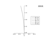
図2Bは、図1の撮像レンズ10の歪曲収差を示すグラフ図である。図2Bにおいて、縦軸は瞳径を1に正規化した入射瞳上の入射高を示し、横軸は結像位置のずれを示す。グラフ中の各線は、グラフ右に示す各波長の光に対する歪曲収差(%)を示す。 FIG. 2B is a graph diagram showing distortion aberration of the imaging lens 10 of FIG. 1. In FIG. 2B, the vertical axis indicates the incident height on the entrance pupil with the pupil diameter normalized to 1, and the horizontal axis indicates the shift in the imaging position. Each line in the graph indicates the distortion (%) for light of each wavelength shown on the right side of the graph.

図2A及び図2Bに示されるように、実施例1によれば、非点及び歪曲の諸収差が良好に補正され、結像性能に優れた撮像レンズ10が得られる。 As shown in FIGS. 2A and 2B, according to Example 1, various aberrations such as astigmatism and distortion are well corrected, and an imaging lens 10 with excellent imaging performance is obtained.

以上の収差図に関する説明は、他の各実施例で示す収差図においても同様に当てはまるため、以下では説明を省略する。 The above explanation regarding the aberration diagrams applies similarly to the aberration diagrams shown in each of the other examples, so the explanation will be omitted below.

(実施例2)
図3は、本開示の実施例2に係る撮像レンズ10のレンズ構成図である。図3は、実施例2に係る撮像レンズ10のレンズ構成を光学断面で示したものである。
(Example 2)
FIG. 3 is a lens configuration diagram of the imaging lens 10 according to Example 2 of the present disclosure. FIG. 3 shows the lens configuration of the imaging lens 10 according to the second embodiment in an optical cross section.

図3に示されるように、実施例2の撮像レンズ10において、第1レンズ110は、負の屈折力及び球面形状を有する、両凹レンズである。第2レンズ120は、負の屈折力及び球面形状を有する、両凹レンズである。第3レンズ130は、正の屈折力及び球面形状を有する、両凸レンズである。第4レンズ140は、正の屈折力及び球面形状を有する、両凸レンズである。第5レンズ150は、負の屈折力及び球面形状を有する、両凹レンズである。第6レンズ160は、正の屈折力及び非球面形状を有する、両凸レンズである。 As shown in FIG. 3, in the imaging lens 10 of Example 2, the first lens 110 is a biconcave lens having negative refractive power and a spherical shape. The second lens 120 is a biconcave lens with negative refractive power and a spherical shape. The third lens 130 is a biconvex lens with positive refractive power and a spherical shape. The fourth lens 140 is a biconvex lens with positive refractive power and a spherical shape. The fifth lens 150 is a biconcave lens with negative refractive power and a spherical shape. The sixth lens 160 is a biconvex lens with positive refractive power and an aspherical shape.

表5は、実施例2に係る撮像レンズ10の諸元値を含む基本レンズデータを示す。表5において、※で示される非球面としての面S11及びS12に対しては、曲率半径Riの値は、近軸曲率半径を示している。

Figure 2024032572000007
※は非球面 Table 5 shows basic lens data including specification values of the imaging lens 10 according to the second embodiment. In Table 5, for the aspheric surfaces S11 and S12 indicated by *, the value of the radius of curvature Ri indicates the paraxial radius of curvature.
Figure 2024032572000007
*Aspherical surface

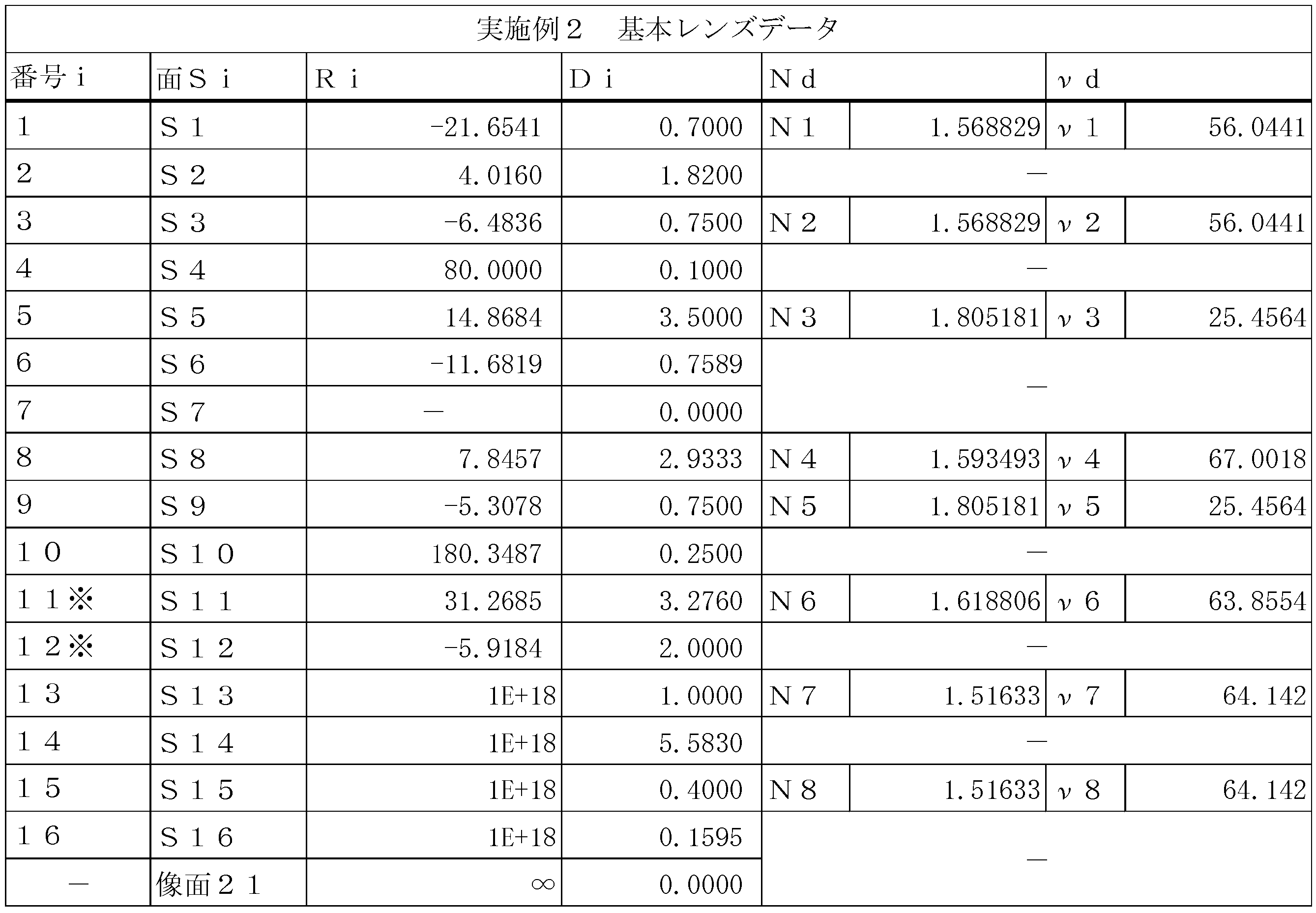
表6は、実施例2に係る撮像レンズ10の非球面係数を含む非球面データを示す。表6に示す非球面データは、第6レンズ160の面S11及びS12の各々に対するデータである。

Figure 2024032572000008
Table 6 shows aspherical surface data including aspherical coefficients of the imaging lens 10 according to Example 2. The aspherical surface data shown in Table 6 is data for each of surfaces S11 and S12 of the sixth lens 160.
Figure 2024032572000008

図4A及び図4Bは、図3の撮像レンズ10の収差図である。図4Aは、図3の撮像レンズ10の非点収差を示すグラフ図である。図4Bは、図3の撮像レンズ10の歪曲収差を示すグラフ図である。図4A及び図4Bに示されるように、実施例2によれば、非点及び歪曲の諸収差が良好に補正され、結像性能に優れた撮像レンズ10が得られる。 4A and 4B are aberration diagrams of the imaging lens 10 of FIG. 3. FIG. 4A is a graph diagram showing astigmatism of the imaging lens 10 of FIG. 3. FIG. FIG. 4B is a graph diagram showing distortion aberration of the imaging lens 10 of FIG. 3. FIG. As shown in FIGS. 4A and 4B, according to Example 2, various aberrations such as astigmatism and distortion are well corrected, and an imaging lens 10 with excellent imaging performance can be obtained.

(実施例3)
図5は、本開示の実施例3に係る撮像レンズ10のレンズ構成図である。図5は、実施例3に係る撮像レンズ10のレンズ構成を光学断面で示したものである。
(Example 3)
FIG. 5 is a lens configuration diagram of the imaging lens 10 according to Example 3 of the present disclosure. FIG. 5 shows the lens configuration of the imaging lens 10 according to the third embodiment in an optical cross section.

図5に示されるように、実施例3の撮像レンズ10において、第1レンズ110は、負の屈折力及び球面形状を有する、両凹レンズである。第2レンズ120は、負の屈折力及び球面形状を有する、両凹レンズである。第3レンズ130は、正の屈折力及び球面形状を有する、両凸レンズである。第4レンズ140は、正の屈折力及び球面形状を有する、両凸レンズである。第5レンズ150は、負の屈折力及び球面形状を有する、両凹レンズである。第6レンズ160は、正の屈折力及び非球面形状を有する、両凸レンズである。 As shown in FIG. 5, in the imaging lens 10 of Example 3, the first lens 110 is a biconcave lens having negative refractive power and a spherical shape. The second lens 120 is a biconcave lens with negative refractive power and a spherical shape. The third lens 130 is a biconvex lens with positive refractive power and a spherical shape. The fourth lens 140 is a biconvex lens with positive refractive power and a spherical shape. The fifth lens 150 is a biconcave lens with negative refractive power and a spherical shape. The sixth lens 160 is a biconvex lens with positive refractive power and an aspherical shape.

表7は、実施例3に係る撮像レンズ10の諸元値を含む基本レンズデータを示す。表7において、※で示される非球面としての面S11及びS12に対しては、曲率半径Riの値は、近軸曲率半径を示している。

Figure 2024032572000009
※は非球面 Table 7 shows basic lens data including specification values of the imaging lens 10 according to the third embodiment. In Table 7, for the aspheric surfaces S11 and S12 indicated by *, the value of the radius of curvature Ri indicates the paraxial radius of curvature.
Figure 2024032572000009
*Aspherical surface

表8は、実施例3に係る撮像レンズ10の非球面係数を含む非球面データを示す。表8に示す非球面データは、第6レンズ160の面S11及びS12の各々に対するデータである。

Figure 2024032572000010
Table 8 shows aspherical surface data including aspherical coefficients of the imaging lens 10 according to Example 3. The aspherical surface data shown in Table 8 is data for each of surfaces S11 and S12 of the sixth lens 160.
Figure 2024032572000010

図6A及び図6Bは、図5の撮像レンズ10の収差図である。図6Aは、図5の撮像レンズ10の非点収差を示すグラフ図である。図6Bは、図5の撮像レンズ10の歪曲収差を示すグラフ図である。図6A及び図6Bに示されるように、実施例3によれば、非点及び歪曲の諸収差が良好に補正され、結像性能に優れた撮像レンズ10が得られる。 6A and 6B are aberration diagrams of the imaging lens 10 of FIG. 5. FIG. 6A is a graph diagram showing astigmatism of the imaging lens 10 of FIG. 5. FIG. FIG. 6B is a graph diagram showing distortion aberration of the imaging lens 10 of FIG. 5. FIG. As shown in FIGS. 6A and 6B, according to Example 3, various aberrations such as astigmatism and distortion are well corrected, and an imaging lens 10 with excellent imaging performance is obtained.

(実施例4)
図7は、本開示の実施例4に係る撮像レンズ10のレンズ構成図である。図7は、実施例4に係る撮像レンズ10のレンズ構成を光学断面で示したものである。
(Example 4)
FIG. 7 is a lens configuration diagram of the imaging lens 10 according to Example 4 of the present disclosure. FIG. 7 shows the lens configuration of the imaging lens 10 according to Example 4 in an optical cross section.

図7に示されるように、実施例4の撮像レンズ10において、第1レンズ110は、負の屈折力及び球面形状を有する、両凹レンズである。第2レンズ120は、負の屈折力及び球面形状を有する、両凹レンズである。第3レンズ130は、正の屈折力及び球面形状を有する、両凸レンズである。第4レンズ140は、正の屈折力及び球面形状を有する、両凸レンズである。第5レンズ150は、負の屈折力及び球面形状を有する、両凹レンズである。第6レンズ160は、正の屈折力及び非球面形状を有する、両凸レンズである。 As shown in FIG. 7, in the imaging lens 10 of Example 4, the first lens 110 is a biconcave lens having negative refractive power and a spherical shape. The second lens 120 is a biconcave lens with negative refractive power and a spherical shape. The third lens 130 is a biconvex lens with positive refractive power and a spherical shape. The fourth lens 140 is a biconvex lens with positive refractive power and a spherical shape. The fifth lens 150 is a biconcave lens with negative refractive power and a spherical shape. The sixth lens 160 is a biconvex lens with positive refractive power and an aspherical shape.

表9は、実施例4に係る撮像レンズ10の諸元値を含む基本レンズデータを示す。表9において、※で示される非球面としての面S11及びS12に対しては、曲率半径Riの値は、近軸曲率半径を示している。

Figure 2024032572000011
※は非球面 Table 9 shows basic lens data including specification values of the imaging lens 10 according to Example 4. In Table 9, for the aspheric surfaces S11 and S12 indicated by *, the value of the radius of curvature Ri indicates the paraxial radius of curvature.
Figure 2024032572000011
*Aspherical surface

表10は、実施例4に係る撮像レンズ10の非球面係数を含む非球面データを示す。表10に示す非球面データは、第6レンズ160の面S11及びS12の各々に対するデータである。

Figure 2024032572000012
Table 10 shows aspherical surface data including aspherical coefficients of the imaging lens 10 according to Example 4. The aspherical surface data shown in Table 10 is data for each of surfaces S11 and S12 of the sixth lens 160.
Figure 2024032572000012

図8A及び図8Bは、図7の撮像レンズ10の収差図である。図8Aは、図7の撮像レンズ10の非点収差を示すグラフ図である。図8Bは、図7の撮像レンズ10の歪曲収差を示すグラフ図である。図8A及び図8Bに示されるように、実施例4によれば、非点及び歪曲の諸収差が良好に補正され、結像性能に優れた撮像レンズ10が得られる。 8A and 8B are aberration diagrams of the imaging lens 10 of FIG. 7. FIG. 8A is a graph diagram showing astigmatism of the imaging lens 10 of FIG. 7. FIG. 8B is a graph diagram showing distortion aberration of the imaging lens 10 of FIG. 7. As shown in FIGS. 8A and 8B, according to Example 4, various aberrations such as astigmatism and distortion are well corrected, and an imaging lens 10 with excellent imaging performance is obtained.

(実施例5)
図9は、本開示の実施例5に係る撮像レンズ10のレンズ構成図である。図9は、実施例5に係る撮像レンズ10のレンズ構成を光学断面で示したものである。
(Example 5)
FIG. 9 is a lens configuration diagram of the imaging lens 10 according to Example 5 of the present disclosure. FIG. 9 shows the lens configuration of the imaging lens 10 according to the fifth embodiment in an optical cross section.

図9に示されるように、実施例5の撮像レンズ10において、第1レンズ110は、負の屈折力及び球面形状を有する、両凹レンズである。第2レンズ120は、負の屈折力及び球面形状を有する、両凹レンズである。第3レンズ130は、正の屈折力及び球面形状を有する、両凸レンズである。第4レンズ140は、正の屈折力及び球面形状を有する、両凸レンズである。第5レンズ150は、負の屈折力及び球面形状を有する、両凹レンズである。第6レンズ160は、正の屈折力及び非球面形状を有する、両凸レンズである。 As shown in FIG. 9, in the imaging lens 10 of Example 5, the first lens 110 is a biconcave lens having negative refractive power and a spherical shape. The second lens 120 is a biconcave lens with negative refractive power and a spherical shape. The third lens 130 is a biconvex lens with positive refractive power and a spherical shape. The fourth lens 140 is a biconvex lens with positive refractive power and a spherical shape. The fifth lens 150 is a biconcave lens with negative refractive power and a spherical shape. The sixth lens 160 is a biconvex lens with positive refractive power and an aspherical shape.

表11は、実施例5に係る撮像レンズ10の諸元値を含む基本レンズデータを示す。表11において、※で示される非球面としての面S11及びS12に対しては、曲率半径Riの値は、近軸曲率半径を示している。

Figure 2024032572000013
※は非球面 Table 11 shows basic lens data including specification values of the imaging lens 10 according to Example 5. In Table 11, for the aspheric surfaces S11 and S12 indicated by *, the value of the radius of curvature Ri indicates the paraxial radius of curvature.
Figure 2024032572000013
*Aspherical surface

表12は、実施例5に係る撮像レンズ10の非球面係数を含む非球面データを示す。表12に示す非球面データは、第6レンズ160の面S11及びS12の各々に対するデータである。

Figure 2024032572000014
Table 12 shows aspherical surface data including aspherical coefficients of the imaging lens 10 according to Example 5. The aspherical surface data shown in Table 12 is data for each of surfaces S11 and S12 of the sixth lens 160.
Figure 2024032572000014

図10A及び図10Bは、図9の撮像レンズ10の収差図である。図10Aは、図9の撮像レンズ10の非点収差を示すグラフ図である。図10Bは、図9の撮像レンズ10の歪曲収差を示すグラフ図である。図10A及び図10Bに示されるように、実施例5によれば、非点及び歪曲の諸収差が良好に補正され、結像性能に優れた撮像レンズ10が得られる。 10A and 10B are aberration diagrams of the imaging lens 10 of FIG. 9. FIG. 10A is a graph diagram showing astigmatism of the imaging lens 10 of FIG. 9. FIG. FIG. 10B is a graph diagram showing distortion aberration of the imaging lens 10 of FIG. 9. As shown in FIGS. 10A and 10B, according to Example 5, various aberrations such as astigmatism and distortion are well corrected, and an imaging lens 10 with excellent imaging performance can be obtained.

(実施例6)
図11は、本開示の実施例6に係る撮像レンズ10のレンズ構成図である。図11は、実施例6に係る撮像レンズ10のレンズ構成を光学断面で示したものである。
(Example 6)
FIG. 11 is a lens configuration diagram of the imaging lens 10 according to Example 6 of the present disclosure. FIG. 11 shows an optical cross section of the lens configuration of the imaging lens 10 according to the sixth embodiment.

図11に示されるように、実施例6の撮像レンズ10において、第1レンズ110は、負の屈折力及び球面形状を有する、両凹レンズである。第2レンズ120は、負の屈折力及び球面形状を有する、両凹レンズである。第3レンズ130は、正の屈折力及び球面形状を有する、両凸レンズである。第4レンズ140は、正の屈折力及び球面形状を有する、両凸レンズである。第5レンズ150は、負の屈折力及び球面形状を有する、両凹レンズである。第6レンズ160は、正の屈折力及び非球面形状を有する、両凸レンズである。 As shown in FIG. 11, in the imaging lens 10 of Example 6, the first lens 110 is a biconcave lens having negative refractive power and a spherical shape. The second lens 120 is a biconcave lens with negative refractive power and a spherical shape. The third lens 130 is a biconvex lens with positive refractive power and a spherical shape. The fourth lens 140 is a biconvex lens with positive refractive power and a spherical shape. The fifth lens 150 is a biconcave lens with negative refractive power and a spherical shape. The sixth lens 160 is a biconvex lens with positive refractive power and an aspherical shape.

表13は、実施例6に係る撮像レンズ10の諸元値を含む基本レンズデータを示す。表13において、※で示される非球面としての面S11及びS12に対しては、曲率半径Riの値は、近軸曲率半径を示している。

Figure 2024032572000015
※は非球面 Table 13 shows basic lens data including specification values of the imaging lens 10 according to Example 6. In Table 13, for the aspheric surfaces S11 and S12 indicated by *, the value of the radius of curvature Ri indicates the paraxial radius of curvature.
Figure 2024032572000015
*Aspherical surface

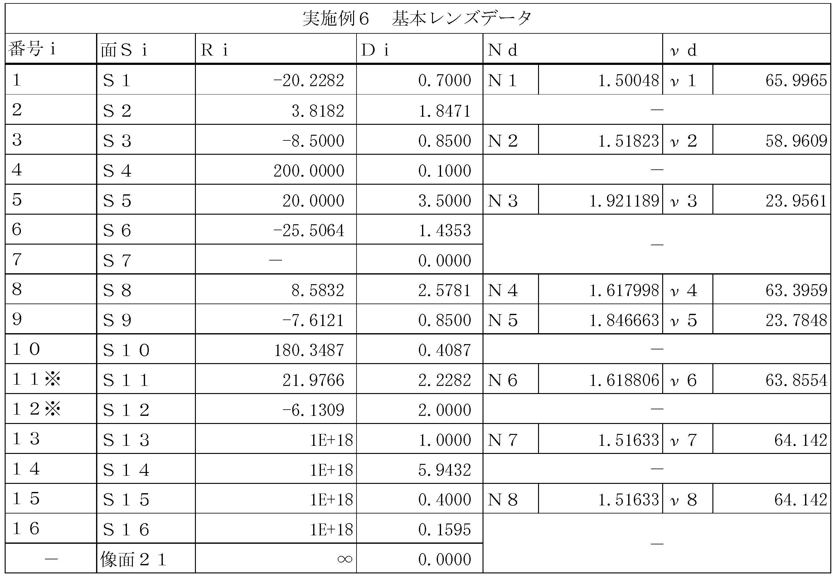
表14は、実施例6に係る撮像レンズ10の非球面係数を含む非球面データを示す。表14に示す非球面データは、第6レンズ160の面S11及びS12の各々に対するデータである。

Figure 2024032572000016
Table 14 shows aspherical surface data including aspherical coefficients of the imaging lens 10 according to Example 6. The aspherical surface data shown in Table 14 is data for each of surfaces S11 and S12 of the sixth lens 160.
Figure 2024032572000016

図12A及び図12Bは、図11の撮像レンズ10の収差図である。図12Aは、図11の撮像レンズ10の非点収差を示すグラフ図である。図12Bは、図11の撮像レンズ10の歪曲収差を示すグラフ図である。図12A及び図12Bに示されるように、実施例6によれば、非点及び歪曲の諸収差が良好に補正され、結像性能に優れた撮像レンズ10が得られる。 12A and 12B are aberration diagrams of the imaging lens 10 of FIG. 11. FIG. 12A is a graph diagram showing astigmatism of the imaging lens 10 of FIG. 11. FIG. 12B is a graph diagram showing distortion aberration of the imaging lens 10 of FIG. 11. As shown in FIGS. 12A and 12B, according to Example 6, various aberrations such as astigmatism and distortion are well corrected, and an imaging lens 10 with excellent imaging performance can be obtained.

(実施例7)
図13は、本開示の実施例7に係る撮像レンズ10のレンズ構成図である。図13は、実施例7に係る撮像レンズ10のレンズ構成を光学断面で示したものである。
(Example 7)
FIG. 13 is a lens configuration diagram of the imaging lens 10 according to Example 7 of the present disclosure. FIG. 13 shows the lens configuration of the imaging lens 10 according to Example 7 in an optical cross section.

図13に示されるように、実施例7の撮像レンズ10において、第1レンズ110は、負の屈折力及び球面形状を有する、両凹レンズである。第2レンズ120は、負の屈折力及び球面形状を有する、両凹レンズである。第3レンズ130は、正の屈折力及び球面形状を有する、両凸レンズである。第4レンズ140は、正の屈折力及び球面形状を有する、両凸レンズである。第5レンズ150は、負の屈折力及び球面形状を有する、両凹レンズである。第6レンズ160は、正の屈折力及び非球面形状を有する、両凸レンズである。 As shown in FIG. 13, in the imaging lens 10 of Example 7, the first lens 110 is a biconcave lens having negative refractive power and a spherical shape. The second lens 120 is a biconcave lens with negative refractive power and a spherical shape. The third lens 130 is a biconvex lens with positive refractive power and a spherical shape. The fourth lens 140 is a biconvex lens with positive refractive power and a spherical shape. The fifth lens 150 is a biconcave lens with negative refractive power and a spherical shape. The sixth lens 160 is a biconvex lens with positive refractive power and an aspherical shape.

表15は、実施例7に係る撮像レンズ10の諸元値を含む基本レンズデータを示す。表15において、※で示される非球面としての面S11及びS12に対しては、曲率半径Riの値は、近軸曲率半径を示している。

Figure 2024032572000017
※は非球面 Table 15 shows basic lens data including specification values of the imaging lens 10 according to Example 7. In Table 15, for the aspheric surfaces S11 and S12 indicated by *, the value of the radius of curvature Ri indicates the paraxial radius of curvature.
Figure 2024032572000017
*Aspherical surface

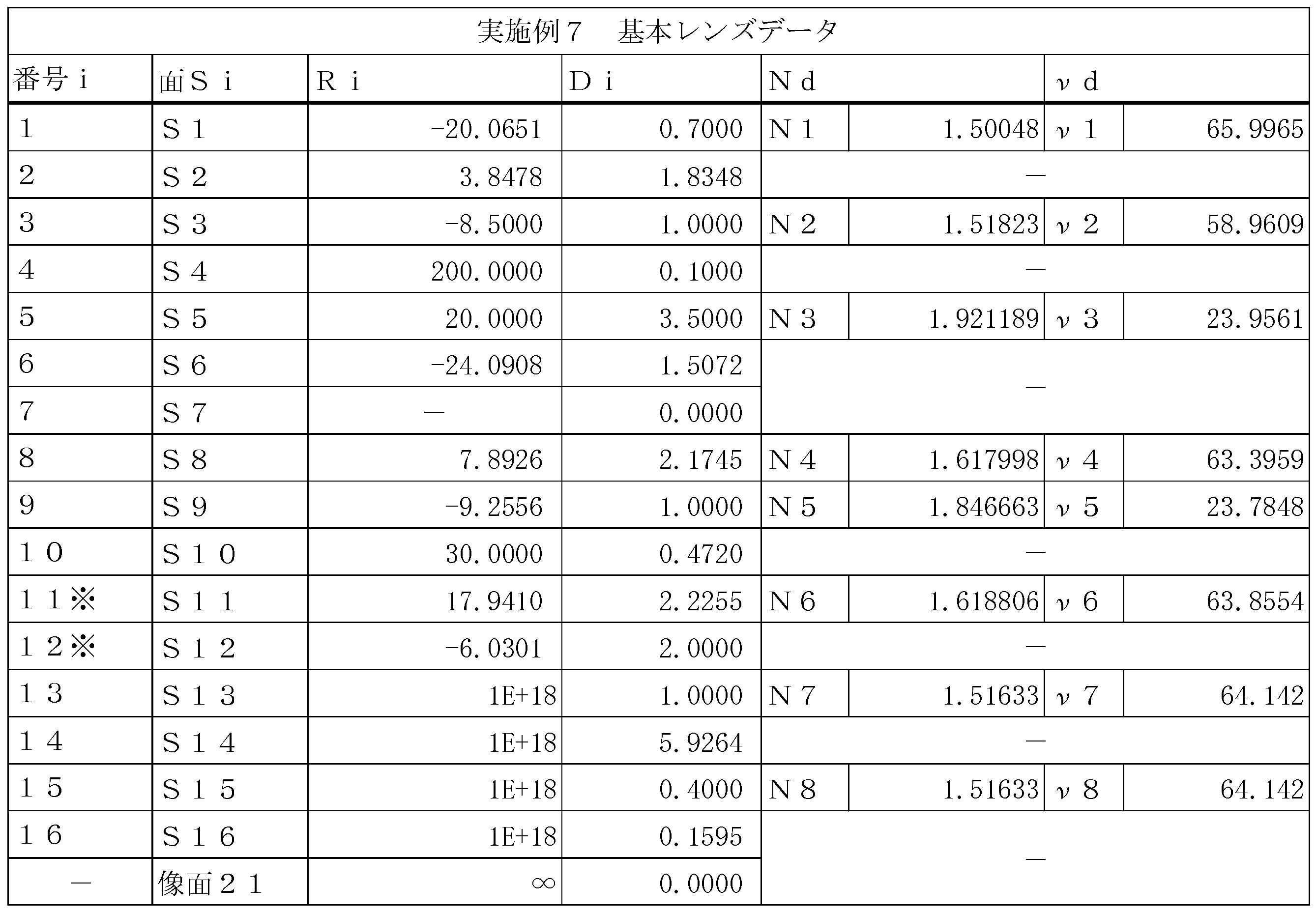
表16は、実施例7に係る撮像レンズ10の非球面係数を含む非球面データを示す。表16に示す非球面データは、第6レンズ160の面S11及びS12の各々に対するデータである。

Figure 2024032572000018
Table 16 shows aspherical surface data including aspherical coefficients of the imaging lens 10 according to Example 7. The aspherical surface data shown in Table 16 is data for each of surfaces S11 and S12 of the sixth lens 160.
Figure 2024032572000018

図14A及び図14Bは、図13の撮像レンズ10の収差図である。図14Aは、図13の撮像レンズ10の非点収差を示すグラフ図である。図14Bは、図13の撮像レンズ10の歪曲収差を示すグラフ図である。図14A及び図14Bに示されるように、実施例7によれば、非点及び歪曲の諸収差が良好に補正され、結像性能に優れた撮像レンズ10が得られる。 14A and 14B are aberration diagrams of the imaging lens 10 of FIG. 13. FIG. 14A is a graph diagram showing astigmatism of the imaging lens 10 of FIG. 13. FIG. 14B is a graph diagram showing the distortion of the imaging lens 10 of FIG. 13. As shown in FIGS. 14A and 14B, according to Example 7, various aberrations such as astigmatism and distortion are well corrected, and an imaging lens 10 with excellent imaging performance is obtained.

(実施例8)
図15は、本開示の実施例8に係る撮像レンズ10のレンズ構成図である。図15は、実施例8に係る撮像レンズ10のレンズ構成を光学断面で示したものである。
(Example 8)
FIG. 15 is a lens configuration diagram of the imaging lens 10 according to Example 8 of the present disclosure. FIG. 15 shows the lens configuration of the imaging lens 10 according to Example 8 in an optical cross section.

図15に示されるように、実施例8の撮像レンズ10において、第1レンズ110は、負の屈折力及び球面形状を有する、両凹レンズである。第2レンズ120は、負の屈折力及び球面形状を有する、両凹レンズである。第3レンズ130は、正の屈折力及び球面形状を有する、両凸レンズである。第4レンズ140は、正の屈折力及び球面形状を有する、両凸レンズである。第5レンズ150は、負の屈折力及び球面形状を有する、両凹レンズである。第6レンズ160は、正の屈折力及び非球面形状を有する、両凸レンズである。 As shown in FIG. 15, in the imaging lens 10 of Example 8, the first lens 110 is a biconcave lens having negative refractive power and a spherical shape. The second lens 120 is a biconcave lens with negative refractive power and a spherical shape. The third lens 130 is a biconvex lens with positive refractive power and a spherical shape. The fourth lens 140 is a biconvex lens with positive refractive power and a spherical shape. The fifth lens 150 is a biconcave lens with negative refractive power and a spherical shape. The sixth lens 160 is a biconvex lens with positive refractive power and an aspherical shape.

表17は、実施例8に係る撮像レンズ10の諸元値を含む基本レンズデータを示す。表17において、※で示される非球面としての面S11及びS12に対しては、曲率半径Riの値は、近軸曲率半径を示している。

Figure 2024032572000019
※は非球面 Table 17 shows basic lens data including specification values of the imaging lens 10 according to Example 8. In Table 17, for the aspheric surfaces S11 and S12 indicated by *, the value of the radius of curvature Ri indicates the paraxial radius of curvature.
Figure 2024032572000019
*Aspherical surface

表18は、実施例8に係る撮像レンズ10の非球面係数を含む非球面データを示す。表18に示す非球面データは、第6レンズ160の面S11及びS12の各々に対するデータである。

Figure 2024032572000020
Table 18 shows aspherical surface data including aspherical coefficients of the imaging lens 10 according to Example 8. The aspherical surface data shown in Table 18 is data for each of surfaces S11 and S12 of the sixth lens 160.
Figure 2024032572000020

図16A及び図16Bは、図15の撮像レンズ10の収差図である。図16Aは、図15の撮像レンズ10の非点収差を示すグラフ図である。図16Bは、図15の撮像レンズ10の歪曲収差を示すグラフ図である。図16A及び図16Bに示されるように、実施例8によれば、非点及び歪曲の諸収差が良好に補正され、結像性能に優れた撮像レンズ10が得られる。 16A and 16B are aberration diagrams of the imaging lens 10 of FIG. 15. FIG. 16A is a graph diagram showing astigmatism of the imaging lens 10 of FIG. 15. FIG. 16B is a graph diagram showing distortion aberration of the imaging lens 10 of FIG. 15. As shown in FIGS. 16A and 16B, according to Example 8, various aberrations such as astigmatism and distortion are well corrected, and an imaging lens 10 with excellent imaging performance can be obtained.

(実施例9)
図17は、本開示の実施例9に係る撮像レンズ10のレンズ構成図である。図17は、実施例9に係る撮像レンズ10のレンズ構成を光学断面で示したものである。
(Example 9)
FIG. 17 is a lens configuration diagram of the imaging lens 10 according to Example 9 of the present disclosure. FIG. 17 shows the lens configuration of the imaging lens 10 according to Example 9 in an optical cross section.

図17に示されるように、実施例9の撮像レンズ10において、第1レンズ110は、負の屈折力及び球面形状を有する、両凹レンズである。第2レンズ120は、負の屈折力及び球面形状を有する、両凹レンズである。第3レンズ130は、正の屈折力及び球面形状を有する、両凸レンズである。第4レンズ140は、正の屈折力及び球面形状を有する、両凸レンズである。第5レンズ150は、負の屈折力及び球面形状を有する、両凹レンズである。第6レンズ160は、正の屈折力及び非球面形状を有する、両凸レンズである。 As shown in FIG. 17, in the imaging lens 10 of Example 9, the first lens 110 is a biconcave lens having negative refractive power and a spherical shape. The second lens 120 is a biconcave lens with negative refractive power and a spherical shape. The third lens 130 is a biconvex lens with positive refractive power and a spherical shape. The fourth lens 140 is a biconvex lens with positive refractive power and a spherical shape. The fifth lens 150 is a biconcave lens with negative refractive power and a spherical shape. The sixth lens 160 is a biconvex lens with positive refractive power and an aspherical shape.

表19は、実施例9に係る撮像レンズ10の諸元値を含む基本レンズデータを示す。表19において、※で示される非球面としての面S11及びS12に対しては、曲率半径Riの値は、近軸曲率半径を示している。

Figure 2024032572000021
※は非球面 Table 19 shows basic lens data including specification values of the imaging lens 10 according to Example 9. In Table 19, for the aspheric surfaces S11 and S12 indicated by *, the value of the radius of curvature Ri indicates the paraxial radius of curvature.
Figure 2024032572000021
*Aspherical surface

表20は、実施例9に係る撮像レンズ10の非球面係数を含む非球面データを示す。表20に示す非球面データは、第6レンズ160の面S11及びS12の各々に対するデータである。

Figure 2024032572000022
Table 20 shows aspherical surface data including aspherical coefficients of the imaging lens 10 according to Example 9. The aspherical surface data shown in Table 20 is data for each of surfaces S11 and S12 of the sixth lens 160.
Figure 2024032572000022

図18A及び図18Bは、図17の撮像レンズ10の収差図である。図18Aは、図17の撮像レンズ10の非点収差を示すグラフ図である。図18Bは、図17の撮像レンズ10の歪曲収差を示すグラフ図である。図18A及び図18Bに示されるように、実施例9によれば、非点及び歪曲の諸収差が良好に補正され、結像性能に優れた撮像レンズ10が得られる。 18A and 18B are aberration diagrams of the imaging lens 10 of FIG. 17. FIG. 18A is a graph diagram showing astigmatism of the imaging lens 10 of FIG. 17. FIG. 18B is a graph diagram showing the distortion of the imaging lens 10 of FIG. 17. As shown in FIGS. 18A and 18B, according to Example 9, various aberrations such as astigmatism and distortion are well corrected, and an imaging lens 10 with excellent imaging performance can be obtained.

以上のような本開示の一実施形態に係る撮像レンズ10及び撮像装置1によれば、6枚構成によって小型、軽量かつ安価でありながら、レンズの形状を適切に設定することにより高い光学性能を実現可能である。その結果、監視用カメラ及び車載用カメラなどを含むカメラに搭載可能なコンパクトで高い光学性能を有する撮像レンズ10及び撮像装置1を実現することが可能である。 According to the above-described imaging lens 10 and imaging device 1 according to an embodiment of the present disclosure, the six-lens configuration is small, lightweight, and inexpensive, while high optical performance is achieved by appropriately setting the shape of the lens. It is possible. As a result, it is possible to realize an imaging lens 10 and an imaging device 1 that are compact and have high optical performance and can be mounted on cameras such as surveillance cameras and vehicle-mounted cameras.

撮像レンズ10は、条件式(1)を満たすことで、非点収差の発生及びメリディオナル方向の像面21の物体側への倒れを抑制可能である。撮像レンズ10は、条件式(2)を満たすことで、軸上色収差を補正することが可能である。 By satisfying conditional expression (1), the imaging lens 10 can suppress the occurrence of astigmatism and the inclination of the image plane 21 in the meridional direction toward the object side. The imaging lens 10 can correct longitudinal chromatic aberration by satisfying conditional expression (2).

撮像レンズ10は、条件式(3)を満たすことで、非点収差の発生を抑制可能である。加えて、撮像レンズ10は、軸上色収差を容易に補正することが可能である。 The imaging lens 10 can suppress the occurrence of astigmatism by satisfying conditional expression (3). In addition, the imaging lens 10 can easily correct axial chromatic aberration.

撮像レンズ10は、条件式(4)を満たすことで、像面湾曲を容易に補正可能であり、負の第5レンズ150による軸上色収差も容易に補正可能である。 By satisfying conditional expression (4), the imaging lens 10 can easily correct field curvature, and can also easily correct axial chromatic aberration due to the negative fifth lens 150.

撮像レンズ10は、第2レンズ120の両面の各々が凹面であることで、第2レンズ120に対して追加の加工を施すことなく、第1レンズ110及びスペーサなどに対し平面で接触させることが可能な平坦受け部を容易に形成することができる。 Since both surfaces of the second lens 120 are concave, the imaging lens 10 can be brought into contact with the first lens 110 and the spacer on a flat surface without performing any additional processing on the second lens 120. Possible flat receivers can be easily formed.

撮像レンズ10は、条件式(5)を満たすことで、非点収差の発生を抑制可能である。加えて、撮像レンズ10は、メリディオナル方向の像面21の湾曲を抑制可能である。 The imaging lens 10 can suppress the occurrence of astigmatism by satisfying conditional expression (5). In addition, the imaging lens 10 can suppress curvature of the image plane 21 in the meridional direction.

撮像レンズ10は、条件式(6)を満たすことで、像面21に入射する光線の入射角を抑制可能である。 The imaging lens 10 can suppress the angle of incidence of the light beam incident on the image plane 21 by satisfying conditional expression (6).

撮像レンズ10は、条件式(7)を満たすことで、非点収差の発生を抑制可能である。 The imaging lens 10 can suppress the occurrence of astigmatism by satisfying conditional expression (7).

撮像レンズ10は、条件式(8)を満たすことで、倍率の色収差を容易に補正可能である。加えて、撮像レンズ10は、安価な材料の選択により、低コスト化を容易に実現可能である。 The imaging lens 10 can easily correct chromatic aberration of magnification by satisfying conditional expression (8). In addition, the cost of the imaging lens 10 can be easily reduced by selecting inexpensive materials.

撮像レンズ10は、条件式(9)を満たすことで、非点収差を抑制可能である。加えて、撮像レンズ10は、全長方向及び径方向での小型化を可能にし、カメラ筐体の設計の自由度を向上させる。 The imaging lens 10 can suppress astigmatism by satisfying conditional expression (9). In addition, the imaging lens 10 enables miniaturization in the overall length direction and radial direction, improving the degree of freedom in designing the camera housing.

撮像レンズ10は、条件式(10)を満たすことで、倍率色収差の逆方向への発生を抑制し、軸上色収差も容易に補正可能である。 By satisfying conditional expression (10), the imaging lens 10 can suppress the occurrence of lateral chromatic aberration in the opposite direction, and can also easily correct axial chromatic aberration.

撮像レンズ10は、条件式(11)を満たすことで、像面湾曲を容易に補正可能である。加えて、撮像レンズ10は、公差感度を低くすることも可能である。 The imaging lens 10 can easily correct field curvature by satisfying conditional expression (11). In addition, the imaging lens 10 can also have low tolerance sensitivity.

撮像レンズ10は、第6レンズ160の両面の各々が非球面であることで、撮像素子20への光の入射角を容易に調整可能である。結果として、撮像レンズ10は、球面収差及び非点収差を容易に補正可能である。 In the imaging lens 10, since both surfaces of the sixth lens 160 are aspherical, the angle of incidence of light onto the imaging element 20 can be easily adjusted. As a result, the imaging lens 10 can easily correct spherical aberration and astigmatism.

撮像レンズ10は、第4レンズ140と第5レンズ150とが接合レンズとして形成されていることで、公差感度の低い光学系を実現可能である。加えて、撮像レンズ10は、撮像レンズ10への組み込みの作業負荷を低減することが可能である。 Since the fourth lens 140 and the fifth lens 150 are formed as a cemented lens, the imaging lens 10 can realize an optical system with low tolerance sensitivity. In addition, the imaging lens 10 can reduce the workload of assembling the imaging lens 10.

撮像レンズ10は、第1レンズ110、第2レンズ120、第3レンズ130、第4レンズ140、第5レンズ150、及び第6レンズ160の各々が硝子材料で形成されていることで、紫外線による黄変及び温度変化による光学特性の変化などを抑制可能である。 The imaging lens 10 has a first lens 110, a second lens 120, a third lens 130, a fourth lens 140, a fifth lens 150, and a sixth lens 160 each made of a glass material. It is possible to suppress yellowing and changes in optical properties due to temperature changes.

撮像レンズ10は、条件式(12)を満たすことで、像面湾曲の発生を抑制可能である。加えて、撮像レンズ10は、軸上色収差を良好に補正することも可能である。 The imaging lens 10 can suppress the occurrence of field curvature by satisfying conditional expression (12). In addition, the imaging lens 10 can also satisfactorily correct axial chromatic aberration.

撮像レンズ10は、条件式(13)を満たすことで、撮像レンズ10全体での軸上色収差を容易に補正可能である。 By satisfying conditional expression (13), the imaging lens 10 can easily correct longitudinal chromatic aberration in the entire imaging lens 10.

撮像レンズ10は、条件式(14)を満たすことで、像面湾曲の発生を抑制し、第3レンズ130で発生する軸上色収差を容易に補正可能である。 By satisfying conditional expression (14), the imaging lens 10 can suppress the occurrence of field curvature and easily correct the longitudinal chromatic aberration occurring in the third lens 130.

撮像レンズ10は、条件式(15)を満たすことで、例えば車載用カメラに用いられる撮像装置1が満たすべき撮像範囲を容易に確保可能である。 By satisfying conditional expression (15), the imaging lens 10 can easily secure an imaging range that should be satisfied by the imaging device 1 used for, for example, a vehicle-mounted camera.

撮像レンズ10は、第1レンズ110の物体側面が凹面であることで、第1レンズ110に対して追加の加工を施すことなく、リテーナなどでの被保持構造を容易に形成することが可能である。加えて、撮像レンズ10は、ゴーストの発生を抑制可能である。 In the imaging lens 10, since the object side surface of the first lens 110 is concave, it is possible to easily form a structure to be held by a retainer or the like without performing additional processing on the first lens 110. be. In addition, the imaging lens 10 can suppress the occurrence of ghosts.

本開示は、その精神又はその本質的な特徴から離れることなく、上述した実施形態以外の他の所定の形態で実現できることは当業者にとって明白である。したがって、先の記述は例示的であり、これに限定されない。開示の範囲は、先の記述によってではなく、付加した請求項によって定義される。あらゆる変更のうちその均等の範囲内にあるいくつかの変更は、その中に包含されるとする。 It will be obvious to those skilled in the art that the present disclosure can be implemented in other predetermined forms than the embodiments described above without departing from the spirit or essential characteristics thereof. Accordingly, the above description is illustrative and not limiting. The scope of the disclosure is defined by the appended claims rather than by the foregoing description. Any changes that come within the range of equivalents are intended to be included therein.

例えば、上述した各構成部の形状、大きさ、配置、向き、及び個数などは、上記の説明及び図面における図示の内容に限定されない。各構成部の形状、大きさ、配置、向き、及び個数などは、その機能を実現できるのであれば、任意に構成されてもよい。 For example, the shape, size, arrangement, orientation, number, etc. of each component described above are not limited to what is illustrated in the above description and drawings. The shape, size, arrangement, orientation, number, etc. of each component may be arbitrarily configured as long as the function can be realized.

一実施形態に係る撮像レンズ10について説明したが、本開示は上述した各実施例の撮像レンズ10に限定されるものではなく、発明の要旨を逸脱しない範囲で種々の変形が可能である。例えば、各実施例の撮像レンズ10の諸元は例示であって、本開示の範囲内で種々のパラメータの変更が可能である。 Although the imaging lens 10 according to one embodiment has been described, the present disclosure is not limited to the imaging lens 10 of each example described above, and various modifications can be made without departing from the gist of the invention. For example, the specifications of the imaging lens 10 in each embodiment are merely examples, and various parameters can be changed within the scope of the present disclosure.

1 撮像装置
10 撮像レンズ
110 第1レンズ
120 第2レンズ
130 第3レンズ
140 第4レンズ
150 第5レンズ
160 第6レンズ
170 開口絞り
180a 第1平板
180b 第2平板
20 撮像素子
21 像面
Ax 光軸
Di 面間隔
Da 全長
Ri 曲率半径
Si 面
1 Imaging device 10 Imaging lens 110 First lens 120 Second lens 130 Third lens 140 Fourth lens 150 Fifth lens 160 Sixth lens 170 Aperture stop 180a First flat plate 180b Second flat plate 20 Imaging element 21 Image plane Ax Optical axis Di Surface spacing Da Total length Ri Radius of curvature Si Surface

Claims (20)

撮像レンズであって、
物体側から順に、負の屈折力を有する第1レンズと、負の屈折力を有する第2レンズと、正の屈折力を有する第3レンズと、開口絞りと、正の屈折力を有する第4レンズと、負の屈折力を有する第5レンズと、正の屈折力を有する第6レンズと、を備え、
前記第4レンズ、前記第5レンズ、及び前記第6レンズのd線に対する合成焦点距離をfg、前記撮像レンズのd線に対する焦点距離をf、前記第5レンズの屈折率をN5とすると、条件式、
1.4<fg/f<1.8 (1)
0.35<N5/f (2)
を満足する、撮像レンズ。
An imaging lens,
In order from the object side, a first lens having a negative refractive power, a second lens having a negative refractive power, a third lens having a positive refractive power, an aperture stop, and a fourth lens having a positive refractive power. A lens, a fifth lens having negative refractive power, and a sixth lens having positive refractive power,
If the combined focal length of the fourth lens, the fifth lens, and the sixth lens for the d-line is fg, the focal length of the imaging lens for the d-line is f, and the refractive index of the fifth lens is N5, then the conditions formula,
1.4<fg/f<1.8 (1)
0.35<N5/f (2)
An imaging lens that satisfies your needs.
請求項1に記載の撮像レンズであって、
前記第4レンズの物体側面の曲率半径をR8、前記第4レンズの像側面の曲率半径をR9とすると、条件式、
-0.4<(R8+R9)/(R8-R9)<0.25 (3)
を満足する、撮像レンズ。
The imaging lens according to claim 1,
If the radius of curvature of the object side surface of the fourth lens is R8, and the radius of curvature of the image side surface of the fourth lens is R9, then the conditional expression
-0.4<(R8+R9)/(R8-R9)<0.25 (3)
An imaging lens that satisfies your needs.
請求項1又は2に記載の撮像レンズであって、
前記第4レンズのd線に対する焦点距離をf4とすると、条件式、
1.2<f4/f<1.8 (4)
を満足する、撮像レンズ。
The imaging lens according to claim 1 or 2,
If the focal length of the fourth lens with respect to the d-line is f4, then the conditional expression:
1.2<f4/f<1.8 (4)
An imaging lens that satisfies your needs.
請求項1又は2に記載の撮像レンズであって、
前記第2レンズの両面の各々は、凹面である、
撮像レンズ。
The imaging lens according to claim 1 or 2,
Each of both surfaces of the second lens is a concave surface.
Imaging lens.
請求項1又は2に記載の撮像レンズであって、
前記第4レンズの軸上厚みをD8とすると、条件式、
0.4<D8/f<0.7 (5)
を満足する、撮像レンズ。
The imaging lens according to claim 1 or 2,
If the axial thickness of the fourth lens is D8, then the conditional expression:
0.4<D8/f<0.7 (5)
An imaging lens that satisfies your needs.
請求項1又は2に記載の撮像レンズであって、
前記第5レンズの像側面から前記第6レンズの物体側面までの軸上距離をD10とすると、条件式、
0.015<D10/f (6)
を満足する、撮像レンズ。
The imaging lens according to claim 1 or 2,
If the axial distance from the image side surface of the fifth lens to the object side surface of the sixth lens is D10, the conditional expression:
0.015<D10/f (6)
An imaging lens that satisfies your needs.
請求項1又は2に記載の撮像レンズであって、
条件式、
R8/f<1.9 (7)
を満足する、撮像レンズ。
The imaging lens according to claim 1 or 2,
conditional expression,
R8/f<1.9 (7)
An imaging lens that satisfies your needs.
請求項1又は2に記載の撮像レンズであって、
前記第2レンズのアッベ数をν2とすると、条件式、
11<ν2/f (8)
を満足する、撮像レンズ。
The imaging lens according to claim 1 or 2,
If the Abbe number of the second lens is ν2, then the conditional expression:
11<ν2/f (8)
An imaging lens that satisfies your needs.
請求項1又は2に記載の撮像レンズであって、
前記撮像レンズの軸上での全長をDaとすると、条件式、
Da/f<5.2 (9)
を満足する、撮像レンズ。
The imaging lens according to claim 1 or 2,
If the total length of the imaging lens on the axis is Da, then the conditional expression:
Da/f<5.2 (9)
An imaging lens that satisfies your needs.
請求項1又は2に記載の撮像レンズであって、
前記第5レンズのd線に対する焦点距離をf5とすると、条件式、
-2.0<f5/f<-1.1 (10)
を満足する、撮像レンズ。
The imaging lens according to claim 1 or 2,
If the focal length of the fifth lens with respect to the d-line is f5, then the conditional expression:
-2.0<f5/f<-1.1 (10)
An imaging lens that satisfies your needs.
請求項1又は2に記載の撮像レンズであって、
前記第6レンズのd線に対する焦点距離をf6とすると、条件式、
1.45<f6/f<1.8 (11)
を満足する、撮像レンズ。
The imaging lens according to claim 1 or 2,
If the focal length of the sixth lens with respect to the d-line is f6, then the conditional expression:
1.45<f6/f<1.8 (11)
An imaging lens that satisfies your needs.
請求項1又は2に記載の撮像レンズであって、
前記第6レンズの両面の各々は、非球面である、
撮像レンズ。
The imaging lens according to claim 1 or 2,
Each of both surfaces of the sixth lens is an aspherical surface.
Imaging lens.
請求項1又は2に記載の撮像レンズであって、
前記第4レンズと前記第5レンズとは、接合レンズとして形成されている、
撮像レンズ。
The imaging lens according to claim 1 or 2,
The fourth lens and the fifth lens are formed as a cemented lens,
Imaging lens.
請求項1又は2に記載の撮像レンズであって、
前記第1レンズ、前記第2レンズ、前記第3レンズ、前記第4レンズ、前記第5レンズ、及び前記第6レンズの各々は、硝子材料で形成されている、
撮像レンズ。
The imaging lens according to claim 1 or 2,
Each of the first lens, the second lens, the third lens, the fourth lens, the fifth lens, and the sixth lens is formed of a glass material.
Imaging lens.
請求項1又は2に記載の撮像レンズであって、
前記第1レンズのd線に対する焦点距離をf1とすると、条件式、
-1.5<f1/f<-1.2 (12)
を満足する、撮像レンズ。
The imaging lens according to claim 1 or 2,
If the focal length of the first lens with respect to the d-line is f1, then the conditional expression:
-1.5<f1/f<-1.2 (12)
An imaging lens that satisfies your needs.
請求項1又は2に記載の撮像レンズであって、
前記第2レンズのd線に対する焦点距離をf2とすると、条件式、
-3.8<f2/f<-2 (13)
を満足する、撮像レンズ。
The imaging lens according to claim 1 or 2,
If the focal length of the second lens with respect to the d-line is f2, then the conditional expression:
-3.8<f2/f<-2 (13)
An imaging lens that satisfies your needs.
請求項1又は2に記載の撮像レンズであって、
前記第3レンズのd線に対する焦点距離をf3とすると、条件式、
1.6<f3/f<3.1 (14)
を満足する、撮像レンズ。
The imaging lens according to claim 1 or 2,
If the focal length of the third lens with respect to the d-line is f3, then the conditional expression:
1.6<f3/f<3.1 (14)
An imaging lens that satisfies your needs.
請求項1又は2に記載の撮像レンズであって、
像面での最大像高位置に入射する光線の半画角をWとすると、条件式、
48<W (15)
を満足する、撮像レンズ。
The imaging lens according to claim 1 or 2,
If the half angle of view of the ray incident on the maximum image height position on the image plane is W, then the conditional expression is
48<W (15)
An imaging lens that satisfies your needs.
請求項1又は2に記載の撮像レンズであって、
前記第1レンズの物体側面は、凹面である、
撮像レンズ。
The imaging lens according to claim 1 or 2,
The object side surface of the first lens is a concave surface.
Imaging lens.
物体側から順に、負の屈折力を有する第1レンズと、負の屈折力を有する第2レンズと、正の屈折力を有する第3レンズと、開口絞りと、正の屈折力を有する第4レンズと、負の屈折力を有する第5レンズと、正の屈折力を有する第6レンズと、を有する撮像レンズと、
前記撮像レンズを介して結像する光学像を電気信号に変換する撮像素子と、
を備え、
前記第4レンズ、前記第5レンズ、及び前記第6レンズのd線に対する合成焦点距離をfg、前記撮像レンズのd線に対する焦点距離をf、前記第5レンズの屈折率をN5とすると、条件式、
1.4<fg/f<1.8 (16)
0.35<N5/f (17)
を満足する、撮像装置。
In order from the object side, a first lens having a negative refractive power, a second lens having a negative refractive power, a third lens having a positive refractive power, an aperture stop, and a fourth lens having a positive refractive power. an imaging lens having a lens, a fifth lens having negative refractive power, and a sixth lens having positive refractive power;
an imaging element that converts an optical image formed through the imaging lens into an electrical signal;
Equipped with
If the combined focal length of the fourth lens, the fifth lens, and the sixth lens for the d-line is fg, the focal length of the imaging lens for the d-line is f, and the refractive index of the fifth lens is N5, then the conditions formula,
1.4<fg/f<1.8 (16)
0.35<N5/f (17)
An imaging device that satisfies the following.
JP2022136294A 2022-08-29 2022-08-29 Imaging lens and imaging device Pending JP2024032572A (en)

Priority Applications (5)

Application Number Priority Date Filing Date Title
JP2022136294A JP2024032572A (en) 2022-08-29 2022-08-29 Imaging lens and imaging device
EP23860228.8A EP4582848A1 (en) 2022-08-29 2023-08-25 Imaging lens and imaging device
CN202380063059.2A CN119790341A (en) 2022-08-29 2023-08-25 Shooting lens and shooting device
US19/107,255 US20260036789A1 (en) 2022-08-29 2023-08-25 Imaging lens and imaging apparatus
PCT/JP2023/030790 WO2024048466A1 (en) 2022-08-29 2023-08-25 Imaging lens and imaging device

Applications Claiming Priority (1)

Application Number Priority Date Filing Date Title
JP2022136294A JP2024032572A (en) 2022-08-29 2022-08-29 Imaging lens and imaging device

Publications (1)

Publication Number Publication Date
JP2024032572A true JP2024032572A (en) 2024-03-12

Family

ID=90192877

Family Applications (1)

Application Number Title Priority Date Filing Date
JP2022136294A Pending JP2024032572A (en) 2022-08-29 2022-08-29 Imaging lens and imaging device

Country Status (1)

Country Link
JP (1) JP2024032572A (en)

Citations (11)

* Cited by examiner, † Cited by third party
Publication number Priority date Publication date Assignee Title
JPH1020189A (en) * 1996-07-03 1998-01-23 Asahi Optical Co Ltd Endoscope objective lens
JP2005010521A (en) * 2003-06-19 2005-01-13 Minolta Co Ltd Imaging apparatus
JP2005221920A (en) * 2004-02-09 2005-08-18 Konica Minolta Opto Inc Super-wide-angle optical system
JP2006171597A (en) * 2004-12-20 2006-06-29 Matsushita Electric Ind Co Ltd Wide angle lens
JP2006349920A (en) * 2005-06-15 2006-12-28 Ricoh Co Ltd Imaging optical system, imaging lens unit, camera, and portable information terminal device
JP2014059466A (en) * 2012-09-18 2014-04-03 Ricoh Co Ltd Imaging lens, image capturing device, and information device
JP2017156570A (en) * 2016-03-02 2017-09-07 株式会社リコー Imaging lens, camera device, and sensing device
JP2018136476A (en) * 2017-02-23 2018-08-30 富士フイルム株式会社 Imaging lens and imaging apparatus
JP2020046565A (en) * 2018-09-20 2020-03-26 マクセル株式会社 Imaging lens system and imaging device
JP2020150427A (en) * 2019-03-14 2020-09-17 株式会社リコー Imaging device, imaging optical system and moving object
WO2022138253A1 (en) * 2020-12-22 2022-06-30 京セラ株式会社 Imaging lens

Patent Citations (11)

* Cited by examiner, † Cited by third party
Publication number Priority date Publication date Assignee Title
JPH1020189A (en) * 1996-07-03 1998-01-23 Asahi Optical Co Ltd Endoscope objective lens
JP2005010521A (en) * 2003-06-19 2005-01-13 Minolta Co Ltd Imaging apparatus
JP2005221920A (en) * 2004-02-09 2005-08-18 Konica Minolta Opto Inc Super-wide-angle optical system
JP2006171597A (en) * 2004-12-20 2006-06-29 Matsushita Electric Ind Co Ltd Wide angle lens
JP2006349920A (en) * 2005-06-15 2006-12-28 Ricoh Co Ltd Imaging optical system, imaging lens unit, camera, and portable information terminal device
JP2014059466A (en) * 2012-09-18 2014-04-03 Ricoh Co Ltd Imaging lens, image capturing device, and information device
JP2017156570A (en) * 2016-03-02 2017-09-07 株式会社リコー Imaging lens, camera device, and sensing device
JP2018136476A (en) * 2017-02-23 2018-08-30 富士フイルム株式会社 Imaging lens and imaging apparatus
JP2020046565A (en) * 2018-09-20 2020-03-26 マクセル株式会社 Imaging lens system and imaging device
JP2020150427A (en) * 2019-03-14 2020-09-17 株式会社リコー Imaging device, imaging optical system and moving object
WO2022138253A1 (en) * 2020-12-22 2022-06-30 京セラ株式会社 Imaging lens

Similar Documents

Publication Publication Date Title
US11099358B2 (en) Photographing lens assembly, image capturing unit and electronic device
JP3594088B1 (en) Imaging lens
JP6732411B2 (en) Imaging lens and imaging device
CN108351494B (en) Imaging lens
JP2009128654A (en) Fisheye imaging lens
JP5398400B2 (en) Imaging lens
JP6664853B2 (en) Imaging lens
US20150116843A1 (en) Lens module
JP6290694B2 (en) Imaging lens and imaging apparatus
JP2021026063A (en) Image capturing lens
WO2009125522A1 (en) Imaging lens
CN104024909B (en) Imaging lens system and camera head
CN115933129A (en) Capture lens
CN117055200A (en) Optical imaging lens
JP5725967B2 (en) Imaging lens
JP2024104245A (en) Imaging lens, imaging device, and vehicle-mounted camera
CN112799219B (en) Optical lens sets, camera modules and electronic equipment
JP7804109B2 (en) Imaging lens system and imaging device
CN113267872B (en) Optical lens and electronic device
JP2019101146A (en) Imaging lens and imaging device including the same
JP5679902B2 (en) Imaging lens
JP2024032572A (en) Imaging lens and imaging device
JP2024032570A (en) Imaging lens and imaging device
JP2024032566A (en) Imaging lens and imaging device
JP2024032578A (en) Imaging lens and imaging device

Legal Events

Date Code Title Description
A621 Written request for application examination

Free format text: JAPANESE INTERMEDIATE CODE: A621

Effective date: 20241217

A131 Notification of reasons for refusal

Free format text: JAPANESE INTERMEDIATE CODE: A131

Effective date: 20250924

A521 Request for written amendment filed

Free format text: JAPANESE INTERMEDIATE CODE: A523

Effective date: 20251120

A131 Notification of reasons for refusal

Free format text: JAPANESE INTERMEDIATE CODE: A131

Effective date: 20260106