JP2023543559A - Inserter for intraocular lenses - Google Patents
Inserter for intraocular lenses Download PDFInfo
- Publication number
- JP2023543559A JP2023543559A JP2023515137A JP2023515137A JP2023543559A JP 2023543559 A JP2023543559 A JP 2023543559A JP 2023515137 A JP2023515137 A JP 2023515137A JP 2023515137 A JP2023515137 A JP 2023515137A JP 2023543559 A JP2023543559 A JP 2023543559A
- Authority
- JP
- Japan
- Prior art keywords
- inserter
- operating
- switching member
- spring arm
- main body
- Prior art date
- Legal status (The legal status is an assumption and is not a legal conclusion. Google has not performed a legal analysis and makes no representation as to the accuracy of the status listed.)
- Granted
Links
Images




Classifications
-
- A—HUMAN NECESSITIES
- A61—MEDICAL OR VETERINARY SCIENCE; HYGIENE
- A61F—FILTERS IMPLANTABLE INTO BLOOD VESSELS; PROSTHESES; DEVICES PROVIDING PATENCY TO, OR PREVENTING COLLAPSING OF, TUBULAR STRUCTURES OF THE BODY, e.g. STENTS; ORTHOPAEDIC, NURSING OR CONTRACEPTIVE DEVICES; FOMENTATION; TREATMENT OR PROTECTION OF EYES OR EARS; BANDAGES, DRESSINGS OR ABSORBENT PADS; FIRST-AID KITS
- A61F2/00—Filters implantable into blood vessels; Prostheses, i.e. artificial substitutes or replacements for parts of the body; Appliances for connecting them with the body; Devices providing patency to, or preventing collapsing of, tubular structures of the body, e.g. stents
- A61F2/02—Prostheses implantable into the body
- A61F2/14—Eye parts, e.g. lenses or corneal implants; Artificial eyes
- A61F2/16—Intraocular lenses
- A61F2/1662—Instruments for inserting intraocular lenses into the eye
- A61F2/1672—Instruments for inserting intraocular lenses into the eye with a two-stage plunger, e.g. rotatable and pushable or rotatable at different speeds
-
- A—HUMAN NECESSITIES
- A61—MEDICAL OR VETERINARY SCIENCE; HYGIENE
- A61F—FILTERS IMPLANTABLE INTO BLOOD VESSELS; PROSTHESES; DEVICES PROVIDING PATENCY TO, OR PREVENTING COLLAPSING OF, TUBULAR STRUCTURES OF THE BODY, e.g. STENTS; ORTHOPAEDIC, NURSING OR CONTRACEPTIVE DEVICES; FOMENTATION; TREATMENT OR PROTECTION OF EYES OR EARS; BANDAGES, DRESSINGS OR ABSORBENT PADS; FIRST-AID KITS
- A61F2/00—Filters implantable into blood vessels; Prostheses, i.e. artificial substitutes or replacements for parts of the body; Appliances for connecting them with the body; Devices providing patency to, or preventing collapsing of, tubular structures of the body, e.g. stents
- A61F2/02—Prostheses implantable into the body
- A61F2/14—Eye parts, e.g. lenses or corneal implants; Artificial eyes
- A61F2/16—Intraocular lenses
- A61F2/1662—Instruments for inserting intraocular lenses into the eye
- A61F2/1667—Instruments for inserting intraocular lenses into the eye with rotatable plungers
-
- A—HUMAN NECESSITIES
- A61—MEDICAL OR VETERINARY SCIENCE; HYGIENE
- A61F—FILTERS IMPLANTABLE INTO BLOOD VESSELS; PROSTHESES; DEVICES PROVIDING PATENCY TO, OR PREVENTING COLLAPSING OF, TUBULAR STRUCTURES OF THE BODY, e.g. STENTS; ORTHOPAEDIC, NURSING OR CONTRACEPTIVE DEVICES; FOMENTATION; TREATMENT OR PROTECTION OF EYES OR EARS; BANDAGES, DRESSINGS OR ABSORBENT PADS; FIRST-AID KITS
- A61F2/00—Filters implantable into blood vessels; Prostheses, i.e. artificial substitutes or replacements for parts of the body; Appliances for connecting them with the body; Devices providing patency to, or preventing collapsing of, tubular structures of the body, e.g. stents
- A61F2/02—Prostheses implantable into the body
- A61F2/14—Eye parts, e.g. lenses or corneal implants; Artificial eyes
- A61F2/16—Intraocular lenses
- A61F2/1662—Instruments for inserting intraocular lenses into the eye
- A61F2/167—Instruments for inserting intraocular lenses into the eye with pushable plungers
Landscapes
- Health & Medical Sciences (AREA)
- Ophthalmology & Optometry (AREA)
- Cardiology (AREA)
- Oral & Maxillofacial Surgery (AREA)
- Transplantation (AREA)
- Engineering & Computer Science (AREA)
- Biomedical Technology (AREA)
- Heart & Thoracic Surgery (AREA)
- Vascular Medicine (AREA)
- Life Sciences & Earth Sciences (AREA)
- Animal Behavior & Ethology (AREA)
- General Health & Medical Sciences (AREA)
- Public Health (AREA)
- Veterinary Medicine (AREA)
- Prostheses (AREA)
Abstract

本発明の主題は、眼内レンズを埋植するための挿入器(1)であって、本体(10)を備え、その本体内に、細長く形成された操作部材(11)が、後端側において部分的に突入しているとともに操作軸線(12)に沿って移動可能に案内されており、操作部材(11)は、操作軸線(12)に沿ったプッシュ操作(P)によるか或いは操作軸線(12)周りのスクリュー操作(S)によるかのいずれかを選択して本体(10)内へと移動させることができ、操作部材(11)は、少なくとも一部の上に螺子山(13)を備えている挿入器である。本発明によれば、本体(10)には、少なくとも一つのスプリングアーム(14)が配置され、当該スプリングアームは、螺子山(13)に面する内面に螺合構造(15)を備え、本体(10)には、スプリングアーム(14)と相互作用する切替部材(16)が、操作軸線(12)周りに回転可能または操作軸線(12)に沿ってスライド可能に配置され、切替部材(16)は、作用接触を介してスプリングアーム(14)と協働し、作用接触に関わる少なくとも一つの切替部材(16)の内面(17)および/またはスプリングアーム(14)の外面(18)が、操作軸線(12)に対して所定の角度(α)で斜めに形成されていることで、切替部材(16)の回転またはスライドが、スプリングアーム(14)の、操作軸線(12)へと向かう弾性変形および操作軸線(12)から離れる弾性変形を生じさせることができ、これにより、螺合構造(15)を螺子山(13)に選択的に係合させるか或いは係合解除させることができる。
The subject of the present invention is an inserter (1) for implanting an intraocular lens, which includes a main body (10), in which an elongated operating member (11) is provided on the rear end side. The actuating member (11) can be moved by a push operation (P) along the actuating axis (12) or by a push actuation (P) along the actuating axis (12). (12) The operating member (11) can be moved into the main body (10) either by operating a surrounding screw (S) or by a screw thread (13) on at least a portion of the operating member (11). It is an inserter equipped with According to the present invention, at least one spring arm (14) is disposed on the main body (10), and the spring arm has a threaded structure (15) on the inner surface facing the thread (13), and In (10), a switching member (16) interacting with the spring arm (14) is arranged rotatably around the operating axis (12) or slidably along the operating axis (12), and the switching member (16) interacts with the spring arm (14). ) cooperates with the spring arm (14) via a working contact, the inner surface (17) of the at least one switching element (16) and/or the outer surface (18) of the spring arm (14) participating in the working contact being By being formed obliquely at a predetermined angle (α) with respect to the operating axis (12), the switching member (16) rotates or slides toward the operating axis (12) of the spring arm (14). An elastic deformation and an elastic deformation away from the operating axis (12) can be produced, thereby allowing the threaded structure (15) to selectively engage or disengage the thread (13). .
Description
本発明は、ヒトの眼に眼内レンズを埋植するための挿入器であって、本体を備え、その本体内に、細長く形成された操作部材が、後端側で部分的に突入しているとともに、操作軸線に沿って移動可能に案内されており、操作部材は、操作軸線に沿ったプッシュ操作によるか或いは操作軸線周りのスクリュー操作によるかのいずれかを選択して本体内へと移動させることができ、操作部材は、少なくとも一部の上に螺子山を備えている挿入器に関する。 The present invention is an inserter for implanting an intraocular lens into a human eye, which includes a main body, into which an elongated operating member partially protrudes on the rear end side. and is guided so as to be movable along the operating axis, and the operating member is moved into the main body by selecting either a push operation along the operating axis or a screw operation around the operating axis. and the operating member relates to an inserter comprising a thread on at least a portion thereof.
ヒトの眼に眼内レンズを埋植するための挿入器はよく知られている。この場合、眼内レンズは、眼に嵌め込まれる少し前に、内部に眼内レンズが組み込まれたレンズカートリッジを用いて挿入器に組み込むことができ、その後、粘弾性物質を加えてから眼内レンズを前側の送出ノズルから眼の後房に送出するようになっている。本体の前側に、挿入器のレンズガイド部が配置されており、送出ノズルは、そのレンズガイド部の開放端を形成している。 Inserters for implanting intraocular lenses into human eyes are well known. In this case, the intraocular lens can be assembled into the inserter using a lens cartridge with the intraocular lens installed inside it shortly before being inserted into the eye, and then the viscoelastic material is added before the intraocular lens is inserted. is delivered from the front delivery nozzle to the posterior chamber of the eye. A lens guide portion of the inserter is arranged on the front side of the body, and the delivery nozzle forms an open end of the lens guide portion.
本体内には、ピストンが操作軸線に沿って移動可能に案内されており、操作軸線に沿って前後の位置で操作部材に接続している当該ピストンは、操作部材を前進させると、それがピストンに伝わって、送出ノズルに向かう方向で眼内レンズに接触することができ、眼内レンズを送出ノズルを通して送出することができる。 A piston is guided in the main body so as to be movable along the operating axis, and the piston is connected to the operating member at front and rear positions along the operating axis. can be transmitted to contact the intraocular lens in a direction toward the delivery nozzle, and the intraocular lens can be delivered through the delivery nozzle.
ピストンを挿入器の本体内部において動かすために、そして、ピストンをレンズガイド部をも通して送出ノズルの方に制御しながらさらに前へと動かすために、操作部材が本体内に突入するように設けられており、これにより、その操作部材を前進させると、ピストンが、操作軸線に沿って先ず眼内レンズに接触し且つそのまま進んで行くことで眼内レンズが後房内に送り出されるまで眼内レンズと一緒に送出ノズルの方に移動させられ得るようになっている。新しい構造の挿入器は、使い捨ての挿入器として利用され、一度使用されてプリロードされた眼内レンズが送り出されると廃棄される。挿入器のこの構造は、一般にプリロードシステムと呼ばれる。 An operating member is provided to protrude into the body of the inserter for moving the piston within the body of the inserter and for controlling the piston further forward toward the delivery nozzle through the lens guide. As a result, when the operating member is advanced, the piston first contacts the intraocular lens along the operating axis and moves forward until the intraocular lens is delivered into the posterior chamber. It is adapted to be able to be moved together with the lens towards the delivery nozzle. The new design of the inserter is utilized as a disposable inserter, used once and discarded after the preloaded intraocular lens is delivered. This structure of the inserter is commonly referred to as a preload system.
操作部材は、通常、操作者、すなわち眼科医によって手動で本体の後方開口部に押し込まれる。ここで、操作部材を操作軸線に沿って動かすために、第一の操作モードでは、手動で操作部材に加えられる純粋なスラスト運動が可能になり、第二の操作モードでは、同じ操作部材に加えられる回転運動が可能になる挿入器が知られている。その点では、新しい構造の挿入器は、プッシュ操作とスクリュー操作の両方を可能にすることができ、そのために、挿入器には、操作モードを切り替えるための然るべき仕組みが設けられる。 The operating member is typically manually pushed into the rear opening of the body by an operator, ie an ophthalmologist. Here, in order to move the operating member along the operating axis, the first operating mode allows a pure thrust movement to be manually applied to the operating member, and the second operating mode allows an additional thrust movement to be applied to the same operating member. Inserters are known that allow rotational movements. In that regard, the new design of the inserter may allow both push and screw operation, for which purpose the inserter is provided with appropriate mechanisms for switching between operating modes.
例えば、特許文献1は、眼内レンズを埋植するための挿入器を開示し、その操作部材は、後ろからのプッシュか或いはスクリュー運動によって本体内に入り込ませることができ、そのスクリュー運動は、操作部材の螺子山と直にネジ結合している切替部材に手動で加えることができる。一方、操作部材が手動で本体内に押し込まれると、切替部材は自由に共回りする。操作部材を後ろから押すか或いは切替部材を回すかのいずれかによって操作部材が本体内に押し込まれると、操作部材がピストンと接触したまま眼内レンズを前側で送出ノズルから送出することができる。
For example,
特許文献2は、ヒトの眼に眼内レンズを埋植するための挿入器のさらに他の態様であって、本体を備え、その本体内に、細長く形成された操作部材が、後端側で部分的に突入しているとともに、操作軸線に沿って移動可能に案内されており、操作部材は、操作軸線に沿った操作部材のプッシュ操作によるか或いは操作軸線周りの操作部材のスクリュー操作によるかのいずれかを選択して本体内へと移動させることができ、そのために、操作部材は、少なくとも一部の上に螺子山を備えている挿入器を開示する。操作部材のプッシュ操作とスクリュー操作を切り替えるために、折り畳みと展開が可能な対向し合う二つの翼状把持部が設けられており、展開した姿勢にすることにより操作モードをプッシュ操作に、畳み込まれた状態ではスクリュー操作に切り替えることができる。プッシュ操作の操作モードではこのとき、折り畳みと展開が可能な翼状把持部は、フィンガーグリップとして機能することができるため、執刀医は、翼状把持部のところで挿入器を人指指と中指の間でつかんで親指を使って後端側で操作部材を本体内に押し込むことができるようになる。翼状把持部が畳み込まれている場合、操作部材は、執刀医の一方の手に本体が保持されつつ執刀医の他方の手により操作部材がねじ込まれることで、本体内に螺入させることができる。 Patent Document 2 discloses yet another embodiment of an inserter for implanting an intraocular lens into a human eye, which includes a main body, and within the main body, an elongated operating member is provided on the rear end side. The actuating member is partially recessed and movably guided along the actuating axis, the actuating member being moved either by a push operation of the actuating member along the actuating axis or by a screw actuating of the actuating member about the actuating axis. can be selectively moved into the body, for which purpose the operating member discloses an inserter comprising a thread on at least a portion thereof. In order to switch between push operation and screw operation of the operating member, two opposing wing-like grips that can be folded and unfolded are provided. In this state, you can switch to screw operation. In the push operating mode, the foldable and unfoldable winged grip can function as a finger grip, allowing the surgeon to place the inserter between the index and middle fingers at the winged grip. You can now grasp it and use your thumb to push the operating member into the main body on the rear end side. When the wing-like grip is folded, the operating member can be screwed into the main body by holding the main body in one hand of the surgeon and screwing the operating member with the surgeon's other hand. can.
挿入器をプッシュ操作にするのかスクリュー操作にするかの設定は、通常は助手により行なわれ、その後、眼科医は、操作モードが予め設定された挿入器を駆使しながら、前方のレンズガイド部における送出ノズルを眼球内に挿入し、次に眼内レンズを後房に入り込ませた状態にするまで操作部材の操作を行うことになる。 Setting the inserter for push operation or screw operation is usually done by an assistant, and then the ophthalmologist uses the inserter with the preset operation mode to insert the inserter into the front lens guide section. The delivery nozzle is inserted into the eyeball, and then the operating member is operated until the intraocular lens is placed in the posterior chamber.
本発明の課題は、ヒトの眼に眼内レンズを埋植するための挿入器をさらに発展させ、挿入器が、眼内レンズを前進させるための操作部材のプッシュ操作とスクリュー操作のできる限り簡単な切替性能を持つようにすることである。特に、プッシュ操作とスクリュー操作との間の操作モードの切り替えは、それ以外の点では挿入器を同じように扱える一方、プッシュ操作とスクリュー操作との間の切替が挿入器の使用の直前に設定可能となるようにできなければならない。 The object of the present invention is to further develop an inserter for implanting an intraocular lens into a human eye, and to make the inserter as easy as possible to push and screw the operating member to advance the intraocular lens. The objective is to have good switching performance. In particular, switching the operating mode between push and screw operation allows the inserter to be otherwise handled similarly, while switching between push and screw operation is set immediately prior to use of the inserter. It must be possible to do so.
この課題は、請求項1のおいて書きに係る挿入器に基づいて、その特徴的な特徴部を組み合わせることにより解決される。本発明の有利な発展態様は、従属請求項に記載されている。
This object is solved on the basis of the inserter according to
本発明は、本体に、少なくとも一つのスプリングアームが配置され、当該スプリングアームは、螺子山に面する内面に螺合構造を備え、本体に、スプリングアームと相互作用する切替部材が操作軸線周りに回転可能または操作軸線に沿ってスライド可能に配置され、切替部材は、作用接触を介してスプリングアームと協働し、作用接触に関わる少なくとも一つの切替部材の内面および/またはスプリングアームの外面が、操作軸線に対して所定の角度で斜めに形成されていることで、切替部材の回転またはスライドが、スプリングアームの、操作軸線へと向かう弾性変形および操作軸線から離れる弾性変形を生じさせることができ、これにより、螺合構造を螺子山に選択的に係合させるか或いは係合解除させることができるという技術的教示を含む。 In the present invention, at least one spring arm is arranged in the main body, the spring arm has a threaded structure on the inner surface facing the thread, and the main body has a switching member that interacts with the spring arm around the operating axis. The switching member is arranged rotatably or slidably along the operating axis, and the switching member cooperates with the spring arm via a working contact, such that the inner surface of the at least one switching member and/or the outer surface of the spring arm involved in the working contact is By being formed obliquely at a predetermined angle with respect to the operating axis, rotation or sliding of the switching member can cause elastic deformation of the spring arm toward and away from the operating axis. , which includes technical teachings that the threaded structure can be selectively engaged or disengaged from the threads.
本発明の中心となる思想は、二つの切替位置の間で手によって回すことができるか或いはずらすことができる切替部材であり、第一の切替位置では、切替部材は、スプリングアーム上の螺合構造を操作部材の螺子山にスクリュー操作のために係合させ、第二の切替位置では、切替部材は、螺合構造を持つスプリングアームを操作部材の螺子山から解放することで、スプリングアームが操作部材側の螺子山との係合が外れた状態になって、最終的に、操作部材がプッシュ操作のために自由にスライドできるようになる。 The central idea of the invention is a switching member that can be turned by hand or displaced between two switching positions, in the first switching position the switching member engages in a threaded engagement on the spring arm. the structure is engaged with the threads of the operating member for screw operation, and in the second switching position, the switching member disengages the spring arm with the threaded structure from the threads of the operating member, so that the spring arm The engagement with the thread on the operating member side is disengaged, and the operating member is finally free to slide for a push operation.
こうして、切替部材が第二の切替位置へと回されると、上記スプリングアーム或いは複数のスプリングアーム(特に、互いに向き合う位置にある二つのスプリングアーム)が、操作軸線に対して自ずと外側へと弾発することで、螺合構造が操作部材の螺子山を解放する。切替部材とスプリングアームとの間の作用的な結び付きは、本発明によれば作用接触により生み出され、その作用接触は、切替部材がスプリングアームに対して軸線方向に変位する際に、操作軸線に対して半径方向で行なわれるスプリングアームの動きが生じさせられるように、つまり、スプリングアームを、操作軸線へと、つまり操作部材の螺子山へと動かすことも、これから再び離れさせることもできるように出来ている。軸線方向はここで、操作軸線に沿って延在する方向を表し、半径方向は、その操作軸線に垂直な方向を表す。その点では、軸線方向と半径方向は、本発明の意味において互いに垂直になっている。 In this way, when the switching member is turned to the second switching position, the spring arm or spring arms (in particular, two spring arms facing each other) naturally spring outward with respect to the operating axis. By firing, the threaded structure releases the thread of the operating member. The operative connection between the switching element and the spring arm is created according to the invention by an operative contact, which, when the switching element is displaced axially with respect to the spring arm, extends along the operating axis. so that a movement of the spring arm that takes place in the radial direction is produced, i.e. the spring arm can be moved towards the actuating axis, that is to say into the thread of the actuating element, and away from this again. It's done. Axial direction here refers to the direction extending along the operating axis, and radial direction refers to the direction perpendicular to the operating axis. In that respect, the axial direction and the radial direction are perpendicular to each other in the sense of the invention.
切替部材の動きによってスプリングアームに動きを生じさせるために、作用接触に関わる少なくとも一つの面(関与面)が傾斜を備えており、その傾斜が、操作軸線の延在する方向に対して或る角度を有している。その場合、その角度は、操作軸線と、上記関与面にあるベクトル、つまり上記内面および/または上記外面にあるベクトル(このベクトルは、上記内面と上記外面の間の接触点または接触線を通って延在する。)との間にとることができる。もちろん、切替部材若しくはスプリングアームの内面および/または外面は、或る角度で作用接触するという本発明の思想から逸脱することなく、湾曲していることも、或いは、その他の態様で平面とは異なるように形成されていることも可能である。 In order to cause a movement of the spring arm by the movement of the switching member, at least one surface involved in the working contact (participating surface) is provided with an inclination, the inclination being a certain degree with respect to the direction in which the operating axis extends. It has an angle. In that case, the angle is between the operating axis and a vector lying on said participating plane, i.e. a vector lying on said inner surface and/or said outer surface (this vector passes through the point of contact or line of contact between said inner surface and said outer surface). ) can be taken between. Of course, the inner and/or outer surfaces of the switching member or the spring arm may also be curved or otherwise deviate from a plane, without departing from the idea of the invention of working contact at an angle. It is also possible that the structure is formed as follows.
スプリングアームの外面が真っ直ぐ、つまり、外面が相応に傾斜または湾曲しているのではなく、操作軸線に対する延在方向に、何らの角度も持たずに延在するように形成されている一方で、関与面の傾斜部が切替部材の内面であってもよい。 While the outer surface of the spring arm is straight, that is, the outer surface is not correspondingly inclined or curved, but is formed in such a way that it extends without any angle in the direction of extension with respect to the operating axis; The inclined portion of the participating surface may be the inner surface of the switching member.
同様に、スプリングアームの外面が真っ直ぐ延び、切替部材の内面が傾斜または湾曲しているのでもよい。 Similarly, the outer surface of the spring arm may extend straight and the inner surface of the switching member may be sloped or curved.
もちろん、切替部材とスプリングアームとの間の本発明による作用原理は、内面と外面のいずれもが傾斜または湾曲を備え、特に、それらが操作軸線に対してそれぞれ同じ角度をなしている場合に特に上手く機能する。しかしながら、内面と外面のいずれの形態であっても、操作軸線に対して相対的に或る角度で傾斜した作用接触となる。切替部材は、一体で構成されている必要はなく、複数の部品により形成されていることで、外からは手で操作できない切替部材の一つの部品に内面が形成されているのでもよい。 Of course, the principle of action according to the invention between the switching element and the spring arm is particularly important if both the inner and outer surfaces are provided with an inclination or curvature, in particular if they each make the same angle to the operating axis. Works well. However, both the inner and outer configurations result in a working contact that is inclined at an angle relative to the operating axis. The switching member does not need to be constructed in one piece, but may be formed from a plurality of parts, and the inner surface may be formed in one part of the switching member that cannot be manually operated from the outside.
さらに有利にも、作用接触に関わる面は、内面および/または外面がコーティング、特に効率的な表面の滑りを互いに可能にするコーティングを備えるのでもよい。 Furthermore, advantageously, the surfaces involved in working contact may be provided with a coating on the inner and/or outer surfaces, in particular a coating that allows efficient sliding of the surfaces relative to each other.
例えば、切替部材は、スライド部材として構成され、本体内または本体上を移動可能に配置されている。上記内面は、スライド部材が本体上で変位する際にその内面がスプリングアームに対して相対的に変位するようにスライド部材上に構成されていればよいので、操作軸線に対する或る角度での作用接触の原理は、スライド部材においても使うことができる。好ましい場合において、切替部材は、環状またはスリーブ状に構成されており、操作部材は、部分的にまたは完全に切替部材により取り囲まれている。 For example, the switching member is configured as a sliding member and is movably arranged within or on the main body. The inner surface may be configured on the slide member so that the inner surface is displaced relative to the spring arm when the slide member is displaced on the main body, so that the inner surface acts at a certain angle with respect to the operating axis. The contact principle can also be used in sliding members. In a preferred case, the switching element is of ring-shaped or sleeve-shaped design, and the actuating element is partially or completely surrounded by the switching element.
切替部材が環状またはスリーブ状に構成されている場合、切替部材は、好ましくは、環状またはスリーブ状の切替部材の回転軸線が操作軸線と一致するように本体上に配置されている。 When the switching member has an annular or sleeve-shaped configuration, the switching member is preferably arranged on the main body such that the axis of rotation of the annular or sleeve-shaped switching member coincides with the operating axis.
ここで、回転可能な切替部材を備えた挿入器の取り扱いは、スライド部材を二つのスナップ嵌め位置の間でスライドさせるよりも簡単且つ快適であるのが一般的であるが、環状またはスリーブ状の形態とされた切替部材が、本体上で操作軸線に沿ってやはりスライド可能で、切替部材が二つのスナップ嵌め位置の間で変位できることも考えられる。 Here, handling of inserters with rotatable switching members is generally easier and more comfortable than sliding a sliding member between two snap-fit positions, but annular or sleeve-shaped It is also conceivable that the shaped switching member is also slidable along the operating axis on the body, so that the switching member can be displaced between two snap-fit positions.
要するに、切替部材は、本体上に配置された状態でのスライド回転可動性を備えることにより、つまり、切替部材が、切替部材と本体との間のネジ状のガイド部により本体上で変位できる場合に、最も好ましい変形例が達成されると考えられる。そうして、切替部材を手で回し、切替部材と本体との間の相応のネジ状のガイドを介した連携が行なわれる場合に、操作軸線に沿った切替部材の変位は、この方法で極めて快適に実現することができる。 In short, if the switching member has sliding rotational mobility when placed on the main body, that is, if the switching member can be displaced on the main body by a threaded guide between the switching member and the main body. It is believed that the most preferred variant is achieved. In this way, the displacement of the switching element along the actuating axis is extremely variable when the switching element is rotated by hand and the connection between the switching element and the body via a corresponding threaded guide takes place. This can be achieved comfortably.
特に、切替部材は、操作軸線周りに手動で回転可能な、内部貫通路のある回転体を形成し、その内部間通路内に少なくとも一つのスプリングアームが突入しているとともに、その内部間通路を操作部材が貫通して延在している。こうして、スプリングアームは、少なくとも部分的に、内側に延在する操作部材と外側の切替部材との間に形成された半径方向ギャップ、特に環状ギャップ内にある。 In particular, the switching member forms a rotary body manually rotatable about the operating axis with an internal passageway into which at least one spring arm extends; An operating member extends therethrough. The spring arm thus lies at least partially in a radial gap, in particular an annular gap, formed between the inwardly extending actuating member and the outer switching member.
さらに別の長所として、上記内面が切替部材の内部貫通路内に形成されているか或いは上記内面が操作軸線の周りを一周する内側コーン部を形成しているかの少なくともいずれかとされている。すなわち、切替部材が操作軸線に沿って変位すると、スプリングアーム側の外面が、切替部材における内面の異なる部位、つまり、切替部材側の内面の異なる半径と接触するようになり、切替部材が軸線方向に第一の方向に動かされるか或いは第二の方向に動かされるかに応じて、その内面が、円錐構造に起因する傾斜により、スプリングアームを操作部材に向けて押すか或いは操作部材との距離を再び拡大させる。切替部材の操作軸線に沿ったこの動きはここで、操作軸線周りの切替部材の回転運動が重ね合わされてもよい。 A further advantage is that the inner surface is formed in an internal passageway of the switching element and/or that it forms an inner cone that goes around the operating axis. That is, when the switching member is displaced along the operating axis, the outer surface on the spring arm side comes into contact with different parts of the inner surface of the switching member, that is, different radii of the inner surface on the switching member side, and the switching member moves in the axial direction. Depending on whether the spring arm is moved in the first direction or in the second direction, its inner surface, due to the inclination caused by the conical structure, pushes the spring arm towards the operating member or at a distance from it. Expand again. This movement of the switching element along the operating axis may here be superimposed with a rotational movement of the switching element about the operating axis.
さらなる長所は、本体が、貫通路のある受け部を備え、その貫通路を操作部材が貫通して延在し、操作部材が、受け部に接して或いは受け部上を少なくとも部分的に回転可能またはスライド可能に受容または配置されている場合に達成される。 A further advantage is that the body comprises a receiving part with a through passage through which the operating member extends, the operating member being at least partially rotatable on or over the receiving part. or achieved when slidably received or arranged.
切替部材は、操作軸線に沿って軸線方向に移動可能および/または操作軸線周りに回転可能に受け部に接して或いは受け部上を案内されるように受容されており、切替部材の後側の部分は、受け部を超えて突出し、その内部には、上記角度で傾斜した切替部材側の内面であって、少なくとも一つのスプリングアームと相互作用する内面が形成されている。 The switching member is received so as to be axially movable along the operating axis and/or rotatably about the operating axis in contact with or guided on the receiving part, and the switching member is arranged on the rear side of the switching member. The part protrudes beyond the receiving part and is formed in its interior with an inner surface on the side of the switching element which is inclined at said angle and which interacts with the at least one spring arm.
要するに、少なくとも一つのスプリングアーム、互いに対向する二つのスプリングアーム、三つ又は四つ又はそれ以上のスプリングアームが、終端側で受け部上或いは受け部内において受け部または本体に配置されていてもよく、それらのスプリングアームが、スリーブ状の受け部の開放端から内側で突出して切替部材の内面と相互作用する。 In short, at least one spring arm, two spring arms opposite each other, three or four or more spring arms may be arranged on or in the receiving part on the receiving part or in the body on the end side; The spring arms project inwardly from the open end of the sleeve-like receiver and interact with the inner surface of the switching member.
例えば、複数のスプリングアームが、とりわけ一周に亘って均等に配分されるようにして、内側の操作部材と外側の切替部材との間に配置されている場合、コレットチャックのような形態を実現することができ、複数のスプリングアームが操作部材とその螺子山の周りを取り囲むように配置されると、一周に亘って均等に配分されるように位置するスプリングアームの複数の螺合構造から出来上がる雌ネジが、略全周に亘って形成される。 For example, if a plurality of spring arms are arranged between the inner actuating member and the outer switching member, especially in an evenly distributed manner over the circumference, a collet chuck-like configuration can be achieved. When a plurality of spring arms are arranged so as to surround the operating member and its threads, a female member is formed from a plurality of threaded structures of the spring arms arranged so as to be evenly distributed over one circumference. A screw is formed over substantially the entire circumference.
しかしながら、本発明による形態は、一箇所の周位置における単体のスプリングアームを用いるもの、例えば、この単体のスプリングアームと対向するように、螺子山を備えた操作部材が、スプリングアームと反対側のベアリングシェル内に保持される場合などでも技術的に可能である。そのような変形例は、同じように一つだけの周位置に配置されている簡易なスライドスイッチとして切替部材が形成されている場合に有利であると考えられる。 However, the embodiment according to the invention uses a single spring arm at one circumferential position, for example, the operating member with a thread is located opposite to the single spring arm on the opposite side of the spring arm. It is technically possible, for example, if it is held within a bearing shell. Such a variant is considered to be advantageous if the switching element is designed as a simple slide switch which is likewise arranged in only one circumferential position.
切替部材に回転運動が手動で加えられる際に切替部材が同時に操作軸線に沿って移動する、つまり、回転運動に直線運動が重なるようにするための連結リンクを作るために、特に有利にも、受け部の外周に、少なくとも一つのスロットが設けられ、切替部材には、内周側に少なくとも一つのピンが形成され、そのピンが上記のスロット内を案内されているのでもよい。このスロットとピンの結合により、一種の連結リンクが作られ、スロットは、好ましくは受け部の周りの一部または全部にわたって螺旋形状に形成されている。例えば、切替部材は、操作軸線周りに90°または180°回転させることができ、これにより、切替部材は、回転とともに操作軸線に沿って変位させられることになり、その変位は、スプリングアーム若しくは切替部材の外面若しくは内面の上記角度による作用接触を介してスプリングアームが操作部材の螺子山にしっかりと押し込まれ、スプリングアームの螺合構造と操作部材の螺子山との間にネジ結合を生じさせることができる程度の大きさである。特に有利にも、周面に均等に配分された互いに対向する二つのスロットまたは三つのスロットは、ネジ状の形態で受け部の外周に設けられ、その中を、切替部材の内面の内側に形成されている対応する位置に設けられたピンが走行することができる。受け部にわたって延在する切替部材の内面のこの領域は、内面における傾斜面が形成されている領域、特に内側コーン部が形成されている領域に隣接している。 Particularly advantageously, in order to create a coupling link such that when a rotational movement is manually applied to the switching element, the switching element simultaneously moves along the operating axis, that is, the rotational movement is superimposed on the linear movement. At least one slot may be provided on the outer periphery of the receiving part, and at least one pin may be formed on the inner periphery of the switching member, and the pin may be guided in the slot. This combination of the slot and the pin creates a type of connecting link, and the slot is preferably formed in a helical shape partially or completely around the receiving part. For example, the switching member can be rotated 90° or 180° about the operating axis, whereby the switching member is displaced along the operating axis with rotation, the displacement being caused by the spring arm or the switching The spring arm is firmly pushed into the thread of the operating member through the angular working contact of the outer or inner surface of the member, creating a threaded connection between the threaded structure of the spring arm and the thread of the operating member. It is large enough to allow Particularly advantageously, two or three mutually opposing slots, evenly distributed over the circumference, are provided in thread-like form on the outer circumference of the receiving part, in which they are formed inside the inner surface of the switching element. The pin provided in the corresponding position can be moved. This region of the inner surface of the switching element extending over the receiving part is adjacent to the region of the inner surface in which the slope is formed, in particular the region in which the inner cone is formed.
特に、有利な実施形態は、切替部材が受け部上にネジ結合により配置され、操作軸線周りに切替部材が回転すると、同時に切替部材が操作軸線に沿って動いていく場合に得られる。 A particularly advantageous embodiment is obtained if the switching element is arranged with a screw connection on the receiving part, such that rotation of the switching element about the operating axis causes simultaneous movement of the switching element along the operating axis.
要するに、本体は、翼状把持部を備えることができ、受け部は、その翼状把持部の後端側に突出部としてつながっている。受け部、翼状把持部およびその他の本体の残りの部分は、一体的に一つの材料で作ることができ、特に、射出成形で製造することができる。 In short, the main body can include a wing-shaped grip, and the receiving part is connected to the rear end side of the wing-shaped grip as a protrusion. The receiving part, the wing-like gripping parts and the remaining parts of the body can be made integrally of one material, in particular produced by injection molding.
さらに、挿入器がレンズカートリッジのための収容手段を備え、そのレンズカートリッジ内に眼内レンズが組み込まれており、このレンズカートリッジが、眼内レンズとともに収容手段内に装着可能とされていれば有利である。この種の挿入器は、挿入器を再滅菌できさえすれば、とりわけ複数回の利用が可能である。もっとも、カートリッジを装填できる挿入器は、一回限りの使い捨て品として形成されていてもよい。 Furthermore, it is advantageous if the inserter is provided with a receiving means for a lens cartridge, in which the intraocular lens is integrated, the lens cartridge being able to be inserted into the receiving means together with the intraocular lens. It is. This type of inserter can be used multiple times, especially if the inserter can be resterilized. However, the inserter into which the cartridge can be loaded may also be designed as a one-time disposable item.
挿入器は、いわゆるプリロードシステムとしても構成することができ、このシステムにより、挿入器が、本体内か或いは本体における前側に配置されたレンズガイド部内の少なくともいずれかに形成された収容室を備え、その中に眼内レンズが予め製造者側で装填されていることで、挿入器が、装填された眼内レンズと一緒にして取扱可能且つ流通可能なユニットを形成する。その点では、本発明による挿入器は、プリロードシステムまたはカートリッジシステムとして機能することができる。 The inserter can also be configured as a so-called preload system, with which the inserter comprises a receiving chamber formed in the main body and/or in a lens guide part arranged on the front side of the main body; With the intraocular lens preloaded therein by the manufacturer, the inserter forms a handleable and communicable unit with the loaded intraocular lens. In that regard, the inserter according to the invention can function as a preload system or a cartridge system.
最後に、本体内にピストンが収容されており、このピストンは、有利にも、回転変換部を介して操作部材により軸線方向にスライド可能とされている。特に、挿入器のスクリュー操作が開始されると、操作部材は必ず回転運動を行うことになる一方で、ピストンは、操作軸線で回転することなく、操作軸線に沿って直線運動しかしない。 Finally, a piston is accommodated in the body, which can advantageously be slidable in the axial direction by means of an actuating member via a rotation converter. In particular, when the screw operation of the inserter is started, the operating member necessarily performs a rotational movement, while the piston only makes a linear movement along the operating axis without rotating on the operating axis.
本体は、有利にも、受け部と一体且つ翼状把持部と一体に一つのプラスチック体だけから作られ、本体における前側に配置されたレンズガイド部は、先端側の送出ノズルにより眼内レンズを送出するように形成され、特に、本体上で取り外し可能に配置されている。 The body is advantageously made of only one plastic body integrally with the receiving part and integrally with the wing-shaped gripping part, and the lens guide part arranged on the front side of the body delivers the intraocular lens by means of the distal delivery nozzle. In particular, it is removably arranged on the body.
以下に、本発明の好ましい実施例の記載により、本発明をさらに良くする手段を図面に基づいて詳細に説明する。 DETAILED DESCRIPTION OF THE PREFERRED EMBODIMENTS In the following, preferred embodiments of the present invention will be described, and means for further improving the present invention will be explained in detail based on the drawings.
図1は、ヒトの眼に眼内レンズを埋植するために使用される挿入器1の斜視図を示す。挿入器1は、主要な構造部品として本体10を備え、その本体内に、把手32が終端側にある細長く形成された操作部材11が、後端側において部分的に挿入されている。操作部材11は、その大半の長さにわたって螺子山13を有した部分があり、その操作部材11は、本体10内に後端側において部分的に挿入されていることで、操作部材11の自由端に把手32が形成されるようになっている。
FIG. 1 shows a perspective view of an
本体10の前方側には、レンズガイド部30が配置され、その中に、詳細には図示していない態様で眼内レンズが収容されている。本体10の主要構成部品は、ほぼ円筒形であるか或いは取り扱いのために人間の手に馴染みやすく作られているとともに、細長く延びた部分を備えており、本体10と、前方側のレンズガイド部30と、後端側に挿入された操作部材11とを備えた挿入器1が、操作軸線12において細長に延在している。操作軸線12はここで、選択的にスライド可能または回転可能な操作部材11のスラスト軸線と回転軸線を同時に形成している。
A
より取り扱い易くするために、本体10の後側の部分には、翼状把持部23があり、これにより、翼状把持部23を使って挿入器1を人指指と中指の間に挟みながら、後側で親指を把手32にのせて押すことができる。翼状把持部23に対して背面側には、操作軸線12周りに回転可能に本体10上に受容された切替部材16が隣接しており、この切替部材16が貫通路を有し、その中を操作部材11が貫通して延在している。切替部材16はここで、切替部材が操作部材11に直に接触せず、特にネジ結合によって直接的に相互作用することがないように本体10上に設置されている。
In order to make it easier to handle, the rear part of the
レンズガイド部30には、投入口33が示されており、ここを通して、挿入器1の使用開始前に粘弾性体を注入することができる。これが、特にレンズガイド部30内の内部空間および内在する眼内レンズを湿潤し、これにより、眼内レンズを送出するプロセスがやり易くなるか若しくは眼内レンズの損傷をなくすようにできる。次に、レンズガイド部30の自由先端部における送出ノズル31を介して、眼内レンズが送り出される。
An
挿入器1は、切替部材16を用いることで、挿入器1の使用のためにプッシュ操作とスクリュー操作の間の切り替えを行なうことができるようにするのに用いられる一つの手段を備えている。切替部材16は、図1の実施例では、プッシュ操作とスクリュー操作の間の切替のために、操作軸線12周りに回転可能に本体10上に形成されており、その切替部材16の、操作部材11との相互作用は、さらに他の図により詳細に示す。
The
図2は、挿入器1を分解図で示し、そこには、挿入器1の主要構成部品が示されているが、本発明を説明するのに必要ないという理由で図示されていないさらに他の挿入器1の構成部品も存在しており、図示されていないとはいえ、それらの部品は、本発明に係る挿入器1の構成部品であることに違いはなく、図は、限定的に理解されるべきものではない。
FIG. 2 shows the
この図は、本体10をレンズガイド部30から切り離して示しており、操作軸線12と一列に並んで示されたレンズガイド部30は、収容室27を備えて構成され、その中に、(支持部の一つが見えている)眼内レンズ24が装填されており、下側に示されたさらに他のレンズガイド部30は、代替的な構成を形成し、レンズカートリッジ25を収容するための収容手段24を備え、その中に、切り離して描かれた眼内レンズ26が装填されている。眼内レンズ26がレンズカートリッジ25内に装填され、次にレンズカートリッジ25が収容手段24内に装填されると、眼内レンズ26は、ピストン28により、前方側で送出ノズル31からヒトの眼の後房内へと送出することができる。挿入器がプリロードシステムとして構成されている場合、収容室27を備えてその中に眼内レンズ26が予め製造者側で装填されている上側に描かれたレンズガイド部30を使用することができる。
This figure shows the
眼内レンズ26を送出するために、ピストン28は、操作軸線12で直線運動を行い、操作部材11がスクリュー操作により本体10内に螺入されると、回転変換部29の働きで、操作部材11の回転運動がピストン25に伝わらない。
In order to deliver the
別の言い方では、眼内レンズ26が収容室27にそのまま収容されたレンズガイド部30を用いない場合、眼内レンズ26が中に組み込まれるレンズカートリッジ25を中に装填することのできる収容手段24を備えて構成されたレンズガイド部30を代わりに用いることができる。こうして、収容室27を備えたレンズガイド部30は、眼内レンズ26が既に工場側で装填された挿入器1が販売されるプリロードシステムを形成する。代替的に、挿入器1は、眼内レンズ26をプリロードせずに提供することもでき、そのときには、レンズガイド部30は、挿入器1を使用する直前になって初めて眼内レンズ26を備えたレンズカートリッジ25を中に装着できる収容手段24を備えており、これは、いわゆるカートリッジシステムと呼ばれる。レンズカートリッジを収容するための収容手段24および/または眼内レンズ26をそのまま収容するための収容室27は、代替的に本体10内に設置することもできるし、或いは、レンズガイド部30が本体10に配置された場合には、収容手段24または収容室27は、レンズガイド部30と本体10との間の領域に形成されている。
In other words, if the
本体10は、翼状把持部23の後ろ側に、射出成形による受け部20を有し、その上に、切替部材16が操作軸線12周りに回転可能に取り付けられている。このとき、受け部20の外面は、受け部20にわたって螺旋の形状で受け部に設けられているスロット21を備え、これにより、切替部材16を操作軸線12周りに回転すると、切替部材16が同時に操作軸線12に沿った動きをするようになる。スロット21の終端部分には、スナップ嵌め手段34が設けられていてもよく、切替部材16が終位置まで回される度に、ユーザに感触によるフィードバックがあり、切替部材16は、自ずと最終姿勢で動かなくなる。切替部材16の内側には、スロット21との作用接続のためにピンが設けられ、それがスロット21内を走行するが、示された図には描かれていないだけなので、図3を参照されたい。
The
受け部20は、スリーブ状に構成され、特に、翼状把持部23の後端側で本体10に一体的に接続されている。受け部20の内側には、例えば、三つのスプリングアーム14が配置され、これらのスプリングアーム14は、受け部20における内側か、或いは、本体10若しくは翼状把持部23の後端側のいずれかに弾力的に根元で固定されている。こうして、スプリングアーム14は、弾性変形によって、操作軸線12に向かって内向きに、或いは、操作軸線12から離れるように外向きに弾性的に動くことができる。力が加わっていないスプリングアーム14の配置では、これらは、互いに若しくは操作軸線12に対して所定の隔たりを有し、それによって、操作部材11上の螺子山13は、スプリングアーム14間の真中を自由に動くことができる。従って、挿入器1の出荷時の状態は、切替部材がプッシュ操作のための切替位置にあることで、スプリングアーム14が継続的に力の加わった状態になく、その戻ろうとする弾性作用が比較的長期の保管期間に亘って保たれることのないような切替部材16の位置に設定されていなければならない。
The receiving
操作軸線12に沿って切替部材16が軸線方向に変位させられることによって、それも特に、操作軸線12に沿った切替部材16の翼状把持部23に向かう変位をスロット21のガイドがもたらすように、切替部材16が好ましくは回転によって翼状把持部23に向かって変位させられるときに中心の操作軸線12に向かうスプリングアーム14の弾性的なバネ運動が生じさせられる。スプリングアーム14は、切替部材の内面16と接触することにより弾性的に操作軸線12に向かって内向きに撓み込み、これにより、スプリングアーム14の内面上の螺合構造15が操作部材11の螺子山13に係合して、挿入器1をスクリュー操作用に設定することができるようになる。
The axial displacement of the switching
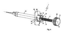
図3および図4は、プッシュ操作Pのための態勢にある挿入器1を図3により示し、スクリュー操作Sのための態勢にある挿入器1を図4で示している。
3 and 4 show the
本体10上の翼状把持部23の後ろ側に受容された切替部材16は、図3では、操作軸線12に沿って把手32の方から見て反時計回りに切替部材が回転されたことによって、翼状把持部23から離れた後方位置にある。このとき、切替部材16の内面上のピン22は、スロット21内を走行し、これにより、切替部材16は、手動で加えられる操作軸線12周りの回転運動により軸線方向に変位して、図3では、切替部材16は、スプリングアーム14を開く後方の位置にあるので、スプリングアーム14が内側の螺合構造15を操作部材11上の螺子山13に係合させないようになっている。
The switching
スプリングアーム14を操作軸線12に向けて半径方向に変位させるために、切替部材16は、切替部材16の内面17の一部を形成する内側コーン部19を備えている。スプリングアーム14の外面18は、切替部材16の内面17に面し、その外面18は、本実施例によれば、内面17と同様に操作軸線12に対して角度αで延びる傾斜を備えている。つまり、切替部材16が操作軸線12に沿って変位すると、切替部材16が翼状把持部23の方に向かって変位するか或いは翼状把持部23から離れるように変位するかに応じて、スプリングアーム14の位置が、互いに接触する内面17と外面18の傾斜若しくは勾配により、半径方向に内側に向かって押されるか或いは半径方向に再び外側に向かって解放される。
In order to displace the
こうして、図3は、スプリングアーム14が、より大きな直径の内側コーン部19上で内面17に接触することにより、スプリングアーム14が弾性的に拡開することができることで、挿入器1をプッシュ操作Pで使用することができるようになるような、翼状把持部23から隔たりのある切替部材16の位置を示している。
Thus, FIG. 3 shows a push operation of the
これに対して、図4は、切替部材が翼状把持部23に押し付けられていることで、スプリングアーム14の外面18が、内側コーン部19が比較的小さな直径を予め有している切替部材16の内面17の領域に接触するようになっており、それにより、螺合構造15が操作部材11の螺子山13と係合するようになる切替部材16の位置を示している。こうして、挿入器1は、スクリュー操作Sで使用することができる。
In contrast, FIG. 4 shows that the switching element is pressed against the wing-
図5および図6は、本体10の受け部20上に切替部材16が配置されている挿入器1のさらに他の実施例を示しており、この切替部材16は、軸線方向に変位する際に、前述のようにスプリングアーム14に作用して、スプリングアームがその内側の螺合構造15を操作部材11の螺子山13に作用接続させる或いは作用接続を解除させることができるようになっている。
FIGS. 5 and 6 show a further embodiment of the
切替部材16が、図5に示されるように、翼状把持部23までの切替部材の隔たりが比較的大きな位置に配置されると、スプリングアーム14は、外側に向かって弾発し、切替部材16が翼状把持部23の方に向かって変位すると、スプリングアーム14は、内側に向かって押され、スプリングアームの内面上の螺合構造15が操作部材11の螺子山13に係合する。
As shown in FIG. 5, when the switching
図5はここで、翼状把持部23までの隔たりが比較的大きいことで、プッシュ操作Pにより挿入器1を使用することができる切替部材16の位置を示し、図6には、翼状把持部23に近づいた位置にある切替部材16が示されており、スプリングアーム14は、挿入器1をスクリュー操作Sで使用することができるように内側に押されている。
FIG. 5 shows the position of the switching
この場合、受け部20上のスロットは、操作軸線12と平行に延びているので、切替部材16は、この実施例によれば回転させることができず、切替部材は、特に、感触によるフィードバックのあるスナップ嵌め位置として構成することのできる前述した二つの終位置の間でユーザによって軸線方向に単にスライドさせることができるに過ぎない。従って、切替部材16がスライダとして構成されていてもよい実施形態が明らかとされ、それによれば、切替部材16は、必ずしも操作部材11を全周にわたって取り囲む必要はなく、切替部材16は、図5および図6による図示されたものとは違って、一つの周位置に配置されたスライダとして構成することもできる。
In this case, the slot on the
従って、この挿入器1は、執刀医が、ヒトの眼に施術する直前であっても、例えば自分の手で或いは手術助手の手を借りて、挿入器1をプッシュ操作Pで使用するか或いはスクリュー操作Sで使用するかを決定することができるという長所をもたらす。把手32は、単に一例として示されたもので、別の構成とされていてもよいし、同じく、翼状把持部23も、横方向に延在するように構成されている必要はなく、操作軸線12周りの鍔部を有したグリッププレートとして構成されていても構わない。図5および図6による実施例はここで、同じく、プリロードシステムとして或いはカートリッジシステムとして使用することができる。
Therefore, the
本発明は、その構成において、上で述べられた好ましい実施例に限定されない。むしろ、基本的に異なる類の構成であっても、示された解決策を利用する多くの変形例が考えられ得る。請求項、明細書または図面から導かれる全ての特徴および/または長所は、構造的な詳細または空間的な配置も含めて、それ自体でも或いはさまざまな組み合わせでも本発明に不可欠であり得る。 The invention is not limited in its construction to the preferred embodiments described above. On the contrary, many variants can be envisaged that make use of the presented solution, even with fundamentally different types of configurations. All features and/or advantages derived from the claims, the description or the drawings, including structural details or spatial arrangements, may be essential to the invention either on their own or in various combinations.
1 挿入器
10 本体
11 操作部材
12 操作軸線
13 螺子山
14 スプリングアーム
15 螺合構造
16 切替部材
17 内面
18 外面
19 内側コーン部
20 受け部
21 スロット
22 ピン
23 翼状把持部
24 収容手段
25 レンズカートリッジ
26 眼内レンズ
27 収容室
28 ピストン
29 回転変換部
30 レンズガイド部
31 送出ノズル
32 把手
33 投入口
34 スナップ嵌め手段
P プッシュ操作
S スクリュー操作
α 角度
1
本発明は、ヒトの眼に眼内レンズを埋植するための挿入器であって、本体を備え、その本体内に、細長く形成された操作部材が、後端側で部分的に突入しているとともに、操作軸線に沿って移動可能に案内されており、操作部材は、操作軸線に沿ったプッシュ操作によるか或いは操作軸線周りのスクリュー操作によるかのいずれかを選択して本体内へと移動させることができ、操作部材は、少なくとも一部の上に螺子山を備え、本体に、切替部材が配置されている挿入器に関する。 The present invention is an inserter for implanting an intraocular lens into a human eye, which includes a main body, into which an elongated operating member partially protrudes on the rear end side. and is guided so as to be movable along the operating axis, and the operating member is moved into the main body by selecting either a push operation along the operating axis or a screw operation around the operating axis. The present invention relates to an inserter in which the operating member is provided with a thread on at least a portion thereof and in which the switching member is disposed in the body .
ヒトの眼に眼内レンズを埋植するための挿入器はよく知られている。この場合、眼内レンズは、眼に嵌め込まれる少し前に、内部に眼内レンズが組み込まれたレンズカートリッジを用いて挿入器に組み込むことができ、その後、粘弾性物質を加えてから眼内レンズを前側の送出ノズルから眼の後房に送出するようになっている。本体の前側に、挿入器のレンズガイド部が配置されており、送出ノズルは、そのレンズガイド部の開放端を形成している。 Inserters for implanting intraocular lenses into human eyes are well known. In this case, the intraocular lens can be assembled into the inserter using a lens cartridge with the intraocular lens installed inside it shortly before being inserted into the eye, and then the viscoelastic material is added before the intraocular lens is inserted. is delivered from the front delivery nozzle to the posterior chamber of the eye. A lens guide portion of the inserter is arranged on the front side of the body, and the delivery nozzle forms an open end of the lens guide portion.
本体内には、ピストンが操作軸線に沿って移動可能に案内されており、操作軸線に沿って前後の位置で操作部材に接続している当該ピストンは、操作部材を前進させると、それがピストンに伝わって、送出ノズルに向かう方向で眼内レンズに接触することができ、眼内レンズを送出ノズルを通して送出することができる。 A piston is guided in the main body so as to be movable along the operating axis, and the piston is connected to the operating member at front and rear positions along the operating axis. can be transmitted to contact the intraocular lens in a direction toward the delivery nozzle, and the intraocular lens can be delivered through the delivery nozzle.
ピストンを挿入器の本体内部において動かすために、そして、ピストンをレンズガイド部をも通して送出ノズルの方に制御しながらさらに前へと動かすために、操作部材が本体内に突入するように設けられており、これにより、その操作部材を前進させると、ピストンが、操作軸線に沿って先ず眼内レンズに接触し且つそのまま進んで行くことで眼内レンズが後房内に送り出されるまで眼内レンズと一緒に送出ノズルの方に移動させられ得るようになっている。新しい構造の挿入器は、使い捨ての挿入器として利用され、一度使用されてプリロードされた眼内レンズが送り出されると廃棄される。挿入器のこの構造は、一般にプリロードシステムと呼ばれる。 An operating member is provided to protrude into the body of the inserter for moving the piston within the body of the inserter and for controlling the piston further forward toward the delivery nozzle through the lens guide. As a result, when the operating member is advanced, the piston first contacts the intraocular lens along the operating axis and moves forward until the intraocular lens is delivered into the posterior chamber. It is adapted to be able to be moved together with the lens towards the delivery nozzle. The new design of the inserter is utilized as a disposable inserter, used once and discarded after the preloaded intraocular lens is delivered. This structure of the inserter is commonly referred to as a preload system.
操作部材は、通常、操作者、すなわち眼科医によって手動で本体の後方開口部に押し込まれる。ここで、操作部材を操作軸線に沿って動かすために、第一の操作モードでは、手動で操作部材に加えられる純粋なスラスト運動が可能になり、第二の操作モードでは、同じ操作部材に加えられる回転運動が可能になる挿入器が知られている。その点では、新しい構造の挿入器は、プッシュ操作とスクリュー操作の両方を可能にすることができ、そのために、挿入器には、操作モードを切り替えるための然るべき仕組みが設けられる。 The operating member is typically manually pushed into the rear opening of the body by an operator, ie an ophthalmologist. Here, in order to move the operating member along the operating axis, the first operating mode allows a pure thrust movement to be manually applied to the operating member, and the second operating mode allows an additional thrust movement to be applied to the same operating member. Inserters are known that allow rotational movements. In that regard, the new design of the inserter may allow both push and screw operation, for which purpose the inserter is provided with appropriate mechanisms for switching between operating modes.
例えば、特許文献1は、眼内レンズを埋植するための挿入器を開示し、その操作部材は、後ろからのプッシュか或いはスクリュー運動によって本体内に入り込ませることができ、そのスクリュー運動は、操作部材の螺子山と直にネジ結合している切替部材に手動で加えることができる。一方、操作部材が手動で本体内に押し込まれると、切替部材は自由に共回りする。操作部材を後ろから押すか或いは切替部材を回すかのいずれかによって操作部材が本体内に押し込まれると、操作部材がピストンと接触したまま眼内レンズを前側で送出ノズルから送出することができる。
For example,
特許文献2は、ヒトの眼に眼内レンズを埋植するための挿入器のさらに他の態様であって、本体を備え、その本体内に、細長く形成された操作部材が、後端側で部分的に突入しているとともに、操作軸線に沿って移動可能に案内されており、操作部材は、操作軸線に沿った操作部材のプッシュ操作によるか或いは操作軸線周りの操作部材のスクリュー操作によるかのいずれかを選択して本体内へと移動させることができ、そのために、操作部材は、少なくとも一部の上に螺子山を備えている挿入器を開示する。操作部材のプッシュ操作とスクリュー操作を切り替えるために、折り畳みと展開が可能な対向し合う二つの翼状把持部が設けられており、展開した姿勢にすることにより操作モードをプッシュ操作に、畳み込まれた状態ではスクリュー操作に切り替えることができる。プッシュ操作の操作モードでは、折り畳みと展開が可能な翼状把持部は、フィンガーグリップとして機能することができるため、執刀医は、翼状把持部のところで挿入器を人指指と中指の間でつかんで親指を使って後端側で操作部材を本体内に押し込むことができるようになる。翼状把持部が畳み込まれている場合、操作部材は、執刀医の一方の手に本体が保持されつつ執刀医の他方の手により操作部材がねじ込まれることで、本体内に螺入させることができる。
特許文献3より、さらに他の挿入器が公知であり、この挿入器は、本体に配置され且つ操作軸線周りに回転可能な貫通路のある切替部材を備え、その貫通路を操作部材が貫通して延在している。操作部材はここで、切替部材の内部輪郭に接触している固定されていないボールと協働し、その内部輪郭が可変な半径を備えている。切替部材が操作軸線周りに回されると、ボールは、解放位置に従って、外側で本体上へ押されるか、或いは、係合位置に従って、本体に設けられた開口部内へと半径方向内向きに押される。操作部材は、解放位置では、本体を自由に通り抜け、係合位置では、ボールが操作部材上の螺子山に係合するため、これを本体内にねじ込むことができる。
特許文献4より、螺子山を有して構成された押圧ピストンを備えた骨セメントまたは人工骨置換材料のための混練配出装置が公知である。押圧ピストンが本体内に押し込まれると、この押圧ピストンが、本体に配置されたラッチと相互作用する。そうして、押圧ピストンは、ラッチによって押圧ピストンが再び外れることを阻止されながら、例えば骨セメントまたは人工骨置換材料が充填された本体内に押し込められることができる。この場合、ラッチは、ネジ山を乗り越えると弾性的に拡開するので、押圧ピストンは、本体内に押し込めることはできても、再び引っ張り出すことができない。より大きな力が必要な場合に、押圧ピストンを押し込むため、そして、骨セメントや骨置換材料などからなる混錬物を送出するため、押圧ピストンをねじ込み動作により中に押しやるために、ロックスリーブを軸方向にラッチに押し付けることができ、これにより、ラッチは、半径方向に弾性的に拡開しなくなるとともに、そのときに限り雌ネジを形成することになり、そこに、押圧ピストンを螺子山により螺入することができるようになっている。
最後に、特許文献5は、プランジャーを備えた医療用の注射器であって、プランジャーが螺子山を備え、注射器のプランジャーは、選択的に、それ自体公知の押圧運動で注射器の本体内に押し込むことができるか、或いは、本体に存在する爪が作動させられ、その爪の作動後にプランジャーが螺子山に係合することで、プランジャーをそれ以上本体内に押し込むことができなくなる一方、ねじ込むことだけはできるようになる注射器を開示する。
Patent Document 2 discloses yet another embodiment of an inserter for implanting an intraocular lens into a human eye, which includes a main body, and within the main body, an elongated operating member is provided on the rear end side. The actuating member is partially recessed and movably guided along the actuating axis, the actuating member being moved either by a push operation of the actuating member along the actuating axis or by a screw actuating of the actuating member about the actuating axis. can be selectively moved into the body, for which purpose the operating member discloses an inserter comprising a thread on at least a portion thereof. In order to switch between push operation and screw operation of the operating member, two opposing wing-like grips that can be folded and unfolded are provided. In this state, you can switch to screw operation. In the push operating mode, the collapsible and unfoldable winged grip can function as a finger grip, allowing the surgeon to grasp the inserter between the index and middle fingers at the winged grip. You can now use your thumb to push the operating member into the main body on the rear end side. When the wing-like grip is folded, the operating member can be screwed into the main body by holding the main body in one hand of the surgeon and screwing the operating member with the surgeon's other hand. can.
Still another inserter is known from US Pat. It has been extended. The actuating member now cooperates with a free ball that is in contact with the internal contour of the switching member, the internal contour of which is provided with a variable radius. When the switching member is turned about the operating axis, the ball is pushed either outwardly onto the body, according to the release position, or radially inwardly into an opening provided in the body, according to the engaged position. It will be done. In the released position, the operating member passes freely through the body, and in the engaged position, the ball engages a thread on the operating member so that it can be screwed into the body.
A kneading and dispensing device for bone cement or artificial bone replacement material is known from US Pat. When the push piston is pushed into the body, it interacts with a latch arranged on the body. The pusher piston can then be pushed into the body filled with, for example, bone cement or artificial bone replacement material, with the latch preventing the pusher piston from coming off again. In this case, the latch expands elastically after overcoming the thread, so that the push piston can be pushed into the body but cannot be pulled out again. The locking sleeve can be pivoted in order to push the push piston in when greater force is required, and in order to force the push piston in with a screwing motion to deliver mixes such as bone cement or bone replacement material. direction, so that the latch no longer expands elastically in the radial direction and only then forms an internal thread, into which the pressing piston can be screwed by means of a thread. It is now possible to enter.
Finally, US Pat. No. 5,002,302 discloses a medical syringe with a plunger, the plunger being provided with a thread, the plunger of the syringe optionally being inserted into the body of the syringe with a pressing movement known per se. Alternatively, a pawl present in the body is actuated, and after actuation of the pawl, the plunger engages with the thread, making it impossible to push the plunger further into the body. , discloses a syringe that can only be screwed on.
挿入器をプッシュ操作にするのかスクリュー操作にするかの設定は、通常は助手により行なわれ、その後、眼科医は、操作モードが予め設定された挿入器を駆使しながら、前方のレンズガイド部における送出ノズルを眼球内に挿入し、次に眼内レンズを後房に入り込ませた状態にするまで操作部材の操作を行うことになる。 Setting the inserter for push operation or screw operation is usually done by an assistant, and then the ophthalmologist uses the inserter with the preset operation mode to insert the inserter into the front lens guide section. The delivery nozzle is inserted into the eyeball, and then the operating member is operated until the intraocular lens is placed in the posterior chamber.
本発明の課題は、ヒトの眼に眼内レンズを埋植するための挿入器をさらに発展させ、挿入器が、眼内レンズを前進させるための操作部材のプッシュ操作とスクリュー操作のできる限り簡単な切替性能を持つようにすることである。特に、プッシュ操作とスクリュー操作との間の操作モードの切り替えは、それ以外の点では挿入器を同じように扱える一方、プッシュ操作とスクリュー操作との間の切替が挿入器の使用の直前に設定可能となるようにできなければならない。 The object of the present invention is to further develop an inserter for implanting an intraocular lens into a human eye, and to make the inserter as easy as possible to push and screw the operating member to advance the intraocular lens. The objective is to have good switching performance. In particular, switching the operating mode between push and screw operation allows the inserter to be otherwise handled similarly, while switching between push and screw operation is set immediately prior to use of the inserter. It must be possible to do so.
この課題は、請求項1のおいて書きに係る挿入器に基づいて、その特徴的な特徴部を組み合わせることにより解決される。本発明の有利な発展態様は、従属請求項に記載されている。
This object is solved on the basis of the inserter according to
本発明は、本体に、少なくとも一つのスプリングアームが配置され、当該スプリングアームは、螺子山に面する内面に螺合構造を備え、切替部材がスプリングアームと相互作用するとともに、操作軸線周りに回転可能または操作軸線に沿ってスライド可能に配置され、切替部材は、作用接触を介してスプリングアームと協働し、作用接触に関わる少なくとも一つの切替部材の内面および/またはスプリングアームの外面が、操作軸線に対して所定の角度で斜めに形成されていることで、切替部材の回転またはスライドが、スプリングアームの、操作軸線へと向かう弾性変形および操作軸線から離れる弾性変形を生じさせることができ、これにより、螺合構造を螺子山に選択的に係合させるか或いは係合解除させることができるという技術的教示を含む。 In the present invention, at least one spring arm is disposed in the main body, the spring arm has a threaded structure on the inner surface facing the thread, and the switching member interacts with the spring arm and rotates around the operating axis. The switching member is disposed slidably along the operating axis, and the switching member cooperates with the spring arm via the working contact, such that the inner surface of the at least one switching member and/or the outer surface of the spring arm involved in the working contact is arranged to be slidable along the operating axis. By being formed obliquely at a predetermined angle with respect to the axis, rotation or sliding of the switching member can cause elastic deformation of the spring arm toward the operating axis and away from the operating axis, This includes the technical teaching that the threaded structure can be selectively engaged or disengaged from the threads.
本発明の中心となる思想は、二つの切替位置の間で手によって回すことができるか或いはずらすことができる切替部材であり、第一の切替位置では、切替部材は、スプリングアーム上の螺合構造を操作部材の螺子山にスクリュー操作のために係合させ、第二の切替位置では、切替部材は、螺合構造を持つスプリングアームを操作部材の螺子山から解放することで、スプリングアームが操作部材側の螺子山との係合が外れた状態になって、最終的に、操作部材がプッシュ操作のために自由にスライドできるようになる。 The central idea of the invention is a switching member that can be turned by hand or displaced between two switching positions, in the first switching position the switching member engages in a threaded engagement on the spring arm. the structure is engaged with the threads of the operating member for screw operation, and in the second switching position, the switching member disengages the spring arm with the threaded structure from the threads of the operating member, so that the spring arm The engagement with the thread on the operating member side is disengaged, and the operating member is finally free to slide for a push operation.
こうして、切替部材が第二の切替位置へと回されると、上記スプリングアーム或いは複数のスプリングアーム(特に、互いに向き合う位置にある二つのスプリングアーム)が、操作軸線に対して自ずと外側へと弾発することで、螺合構造が操作部材の螺子山を解放する。切替部材とスプリングアームとの間の作用的な結び付きは、本発明によれば作用接触により生み出され、その作用接触は、切替部材がスプリングアームに対して軸線方向に変位する際に、操作軸線に対して半径方向で行なわれるスプリングアームの動きが生じさせられるように、つまり、スプリングアームを、操作軸線へと、つまり操作部材の螺子山へと動かすことも、これから再び離れさせることもできるように出来ている。軸線方向はここで、操作軸線に沿って延在する方向を表し、半径方向は、その操作軸線に垂直な方向を表す。その点では、軸線方向と半径方向は、本発明の意味において互いに垂直になっている。 In this way, when the switching member is turned to the second switching position, the spring arm or spring arms (in particular, two spring arms facing each other) naturally spring outward with respect to the operating axis. By firing, the threaded structure releases the thread of the operating member. The operative connection between the switching element and the spring arm is created according to the invention by an operative contact, which, when the switching element is displaced axially with respect to the spring arm, extends along the operating axis. so that a movement of the spring arm that takes place in the radial direction is produced, i.e. the spring arm can be moved towards the actuating axis, that is to say into the thread of the actuating element, and away from this again. It's done. Axial direction here refers to the direction extending along the operating axis, and radial direction refers to the direction perpendicular to the operating axis. In that respect, the axial direction and the radial direction are perpendicular to each other in the sense of the invention.
切替部材の動きによってスプリングアームに動きを生じさせるために、作用接触に関わる少なくとも一つの面(関与面)が傾斜を備えており、その傾斜が、操作軸線の延在する方向に対して或る角度を有している。その場合、その角度は、操作軸線と、上記関与面にあるベクトル、つまり上記内面および/または上記外面にあるベクトル(このベクトルは、上記内面と上記外面の間の接触点または接触線を通って延在する。)との間にとることができる。もちろん、切替部材若しくはスプリングアームの内面および/または外面は、或る角度で作用接触するという本発明の思想から逸脱することなく、湾曲していることも、或いは、その他の態様で平面とは異なるように形成されていることも可能である。 In order to cause a movement of the spring arm by the movement of the switching member, at least one surface involved in the working contact (participating surface) is provided with an inclination, the inclination being a certain degree with respect to the direction in which the operating axis extends. It has an angle. In that case, the angle is between the operating axis and a vector lying on said participating plane, i.e. a vector lying on said inner surface and/or said outer surface (this vector passes through the point of contact or line of contact between said inner surface and said outer surface). ) can be taken between. Of course, the inner and/or outer surfaces of the switching member or the spring arm may also be curved or otherwise deviate from a plane, without departing from the idea of the invention of working contact at an angle. It is also possible that the structure is formed as follows.
スプリングアームの外面が真っ直ぐ、つまり、外面が相応に傾斜または湾曲しているのではなく、操作軸線に対する延在方向に、何らの角度も持たずに延在するように形成されている一方で、関与面の傾斜部が切替部材の内面であってもよい。 While the outer surface of the spring arm is straight, that is, the outer surface is not correspondingly inclined or curved, but is formed in such a way that it extends without any angle in the direction of extension with respect to the operating axis; The inclined portion of the participating surface may be the inner surface of the switching member.
同様に、スプリングアームの外面が真っ直ぐ延び、切替部材の内面が傾斜または湾曲しているのでもよい。 Similarly, the outer surface of the spring arm may extend straight and the inner surface of the switching member may be sloped or curved.
もちろん、切替部材とスプリングアームとの間の本発明による作用原理は、内面と外面のいずれもが傾斜または湾曲を備え、特に、それらが操作軸線に対してそれぞれ同じ角度をなしている場合に特に上手く機能する。しかしながら、内面と外面のいずれの形態であっても、操作軸線に対して相対的に或る角度で傾斜した作用接触となる。切替部材は、一体で構成されている必要はなく、複数の部品により形成されていることで、外からは手で操作できない切替部材の一つの部品に内面が形成されているのでもよい。 Of course, the principle of action according to the invention between the switching element and the spring arm is particularly important if both the inner and outer surfaces are provided with an inclination or curvature, in particular if they each make the same angle to the operating axis. Works well. However, both the inner and outer configurations result in a working contact that is inclined at an angle relative to the operating axis. The switching member does not need to be constructed in one piece, but may be formed from a plurality of parts, and the inner surface may be formed in one part of the switching member that cannot be manually operated from the outside.
さらに有利にも、作用接触に関わる面は、内面および/または外面がコーティング、特に効率的な表面の滑りを互いに可能にするコーティングを備えるのでもよい。 Furthermore, advantageously, the surfaces involved in working contact may be provided with a coating on the inner and/or outer surfaces, in particular a coating that allows efficient sliding of the surfaces relative to each other.
例えば、切替部材は、スライド部材として構成され、本体内または本体上を移動可能に配置されている。上記内面は、スライド部材が本体上で変位する際にその内面がスプリングアームに対して相対的に変位するようにスライド部材上に構成されていればよいので、操作軸線に対する或る角度での作用接触の原理は、スライド部材においても使うことができる。好ましい場合において、切替部材は、環状またはスリーブ状に構成されており、操作部材は、部分的にまたは完全に切替部材により取り囲まれている。 For example, the switching member is configured as a sliding member and is movably arranged within or on the main body. The inner surface may be configured on the slide member so that the inner surface is displaced relative to the spring arm when the slide member is displaced on the main body, so that the inner surface acts at a certain angle with respect to the operating axis. The contact principle can also be used in sliding members. In a preferred case, the switching element is of ring-shaped or sleeve-shaped design, and the actuating element is partially or completely surrounded by the switching element.
切替部材が環状またはスリーブ状に構成されている場合、切替部材は、好ましくは、環状またはスリーブ状の切替部材の回転軸線が操作軸線と一致するように本体上に配置されている。 When the switching member has an annular or sleeve-shaped configuration, the switching member is preferably arranged on the main body such that the axis of rotation of the annular or sleeve-shaped switching member coincides with the operating axis.
ここで、回転可能な切替部材を備えた挿入器の取り扱いは、スライド部材を二つのスナップ嵌め位置の間でスライドさせるよりも簡単且つ快適であるのが一般的であるが、環状またはスリーブ状の形態とされた切替部材が、本体上で操作軸線に沿ってやはりスライド可能で、切替部材が二つのスナップ嵌め位置の間で変位できることも考えられる。 Here, handling of inserters with rotatable switching members is generally easier and more comfortable than sliding a sliding member between two snap-fit positions, but annular or sleeve-shaped It is also conceivable that the shaped switching member is also slidable along the operating axis on the body, so that the switching member can be displaced between two snap-fit positions.
要するに、切替部材は、本体上に配置された状態でのスライド回転可動性を備えることにより、つまり、切替部材が、切替部材と本体との間のネジ状のガイド部により本体上で変位できる場合に、最も好ましい変形例が達成されると考えられる。そうして、切替部材を手で回し、切替部材と本体との間の相応のネジ状のガイドを介した連携が行なわれる場合に、操作軸線に沿った切替部材の変位は、この方法で極めて快適に実現することができる。 In short, if the switching member has sliding rotational mobility when placed on the main body, that is, if the switching member can be displaced on the main body by a threaded guide between the switching member and the main body. It is believed that the most preferred variant is achieved. In this way, the displacement of the switching element along the actuating axis is extremely variable when the switching element is rotated by hand and the connection between the switching element and the body via a corresponding threaded guide takes place. This can be achieved comfortably.
特に、切替部材は、操作軸線周りに手動で回転可能な、内部貫通路のある回転体を形成し、その内部間通路内に少なくとも一つのスプリングアームが突入しているとともに、その内部間通路を操作部材が貫通して延在している。こうして、スプリングアームは、少なくとも部分的に、内側に延在する操作部材と外側の切替部材との間に形成された半径方向ギャップ、特に環状ギャップ内にある。 In particular, the switching member forms a rotary body manually rotatable about the operating axis with an internal passageway into which at least one spring arm extends; An operating member extends therethrough. The spring arm thus lies at least partially in a radial gap, in particular an annular gap, formed between the inwardly extending actuating member and the outer switching member.
さらに別の長所として、上記内面が切替部材の内部貫通路内に形成されているか或いは上記内面が操作軸線の周りを一周する内側コーン部を形成しているかの少なくともいずれかとされている。すなわち、切替部材が操作軸線に沿って変位すると、スプリングアーム側の外面が、切替部材における内面の異なる部位、つまり、切替部材側の内面の異なる半径と接触するようになり、切替部材が軸線方向に第一の方向に動かされるか或いは第二の方向に動かされるかに応じて、その内面が、円錐構造に起因する傾斜により、スプリングアームを操作部材に向けて押すか或いは操作部材との距離を再び拡大させる。切替部材の操作軸線に沿ったこの動きはここで、操作軸線周りの切替部材の回転運動が重ね合わされてもよい。 A further advantage is that the inner surface is formed in an internal passageway of the switching element and/or that it forms an inner cone that goes around the operating axis. That is, when the switching member is displaced along the operating axis, the outer surface on the spring arm side comes into contact with different parts of the inner surface of the switching member, that is, different radii of the inner surface on the switching member side, and the switching member moves in the axial direction. Depending on whether the spring arm is moved in the first direction or in the second direction, its inner surface, due to the inclination caused by the conical structure, pushes the spring arm towards the operating member or at a distance from it. Expand again. This movement of the switching element along the operating axis may here be superimposed with a rotational movement of the switching element about the operating axis.
さらなる長所は、本体が、貫通路のある受け部を備え、その貫通路を操作部材が貫通して延在し、切替部材が、受け部に接して或いは受け部上を少なくとも部分的に回転可能またはスライド可能に受容または配置され、少なくとも一つのスプリングアームは、切替部材の内面と操作部材との間の領域に入り込むように延在している場合に達成される。 A further advantage is that the body comprises a receiving part with a through passage through which the operating member extends, and the switching member is rotatable at least partially on or over the receiving part. or slidably received or arranged , this is achieved if the at least one spring arm extends into the region between the inner surface of the switching member and the operating member.
切替部材は、操作軸線に沿って軸線方向に移動可能および/または操作軸線周りに回転可能に受け部に接して或いは受け部上を案内されるように受容されており、切替部材の後側の部分は、受け部を超えて突出し、その内部には、上記角度で傾斜した切替部材側の内面であって、少なくとも一つのスプリングアームと相互作用する内面が形成されている。 The switching member is received so as to be axially movable along the operating axis and/or rotatably about the operating axis in contact with or guided on the receiving part, and the switching member is arranged on the rear side of the switching member. The part protrudes beyond the receiving part and is formed in its interior with an inner surface on the side of the switching element which is inclined at said angle and which interacts with the at least one spring arm.
要するに、少なくとも一つのスプリングアーム、互いに対向する二つのスプリングアーム、三つ又は四つ又はそれ以上のスプリングアームが、終端側で受け部上或いは受け部内において受け部または本体に配置されていてもよく、それらのスプリングアームが、スリーブ状の受け部の開放端から内側で突出して切替部材の内面と相互作用する。 In short, at least one spring arm, two spring arms opposite each other, three or four or more spring arms may be arranged on or in the receiving part on the receiving part or in the body on the end side; The spring arms project inwardly from the open end of the sleeve-like receiver and interact with the inner surface of the switching member.
例えば、複数のスプリングアームが、とりわけ一周に亘って均等に配分されるようにして、内側の操作部材と外側の切替部材との間に配置されている場合、コレットチャックのような形態を実現することができ、複数のスプリングアームが操作部材とその螺子山の周りを取り囲むように配置されると、一周に亘って均等に配分されるように位置するスプリングアームの複数の螺合構造から出来上がる雌ネジが、略全周に亘って形成される。 For example, if a plurality of spring arms are arranged between the inner actuating member and the outer switching member, especially in an evenly distributed manner over the circumference, a collet chuck-like configuration can be achieved. When a plurality of spring arms are arranged so as to surround the operating member and its threads, a female member is formed from a plurality of threaded structures of the spring arms arranged so as to be evenly distributed over one circumference. A screw is formed over substantially the entire circumference.
しかしながら、本発明による形態は、一箇所の周位置における単体のスプリングアームを用いるもの、例えば、この単体のスプリングアームと対向するように、螺子山を備えた操作部材が、スプリングアームと反対側のベアリングシェル内に保持される場合などでも技術的に可能である。そのような変形例は、同じように一つだけの周位置に配置されている簡易なスライドスイッチとして切替部材が形成されている場合に有利であると考えられる。 However, the embodiment according to the invention uses a single spring arm at one circumferential position, for example, the operating member with a thread is located opposite to the single spring arm on the opposite side of the spring arm. It is technically possible, for example, if it is held within a bearing shell. Such a variant is considered to be advantageous if the switching element is designed as a simple slide switch which is likewise arranged in only one circumferential position.
切替部材に回転運動が手動で加えられる際に切替部材が同時に操作軸線に沿って移動する、つまり、回転運動に直線運動が重なるようにするための連結リンクを作るために、特に有利にも、受け部の外周に、少なくとも一つのスロットが設けられ、切替部材には、内周側に少なくとも一つのピンが形成され、そのピンが上記のスロット内を案内されているのでもよい。このスロットとピンの結合により、一種の連結リンクが作られ、スロットは、好ましくは受け部の周りの一部または全部にわたって螺旋形状に形成されている。例えば、切替部材は、操作軸線周りに90°または180°回転させることができ、これにより、切替部材は、回転とともに操作軸線に沿って変位させられることになり、その変位は、スプリングアーム若しくは切替部材の外面若しくは内面の上記角度による作用接触を介してスプリングアームが操作部材の螺子山にしっかりと押し込まれ、スプリングアームの螺合構造と操作部材の螺子山との間にネジ結合を生じさせることができる程度の大きさである。特に有利にも、周面に均等に配分された互いに対向する二つのスロットまたは三つのスロットは、ネジ状の形態で受け部の外周に設けられ、その中を、切替部材の内面の内側に形成されている対応する位置に設けられたピンが走行することができる。受け部にわたって延在する切替部材の内面のこの領域は、内面における傾斜面が形成されている領域、特に内側コーン部が形成されている領域に隣接している。 Particularly advantageously, in order to create a coupling link such that when a rotational movement is manually applied to the switching element, the switching element simultaneously moves along the operating axis, that is, the rotational movement is superimposed on the linear movement. At least one slot may be provided on the outer periphery of the receiving part, and at least one pin may be formed on the inner periphery of the switching member, and the pin may be guided in the slot. This combination of the slot and the pin creates a type of connecting link, and the slot is preferably formed in a helical shape partially or completely around the receiving part. For example, the switching member can be rotated 90° or 180° about the operating axis, whereby the switching member is displaced along the operating axis with rotation, the displacement being caused by the spring arm or the switching The spring arm is firmly pushed into the thread of the operating member through the angular working contact of the outer or inner surface of the member, creating a threaded connection between the threaded structure of the spring arm and the thread of the operating member. It is large enough to allow Particularly advantageously, two or three mutually opposing slots, evenly distributed over the circumference, are provided in thread-like form on the outer circumference of the receiving part, in which they are formed inside the inner surface of the switching element. The pin provided in the corresponding position can be moved. This region of the inner surface of the switching element extending over the receiving part is adjacent to the region of the inner surface in which the slope is formed, in particular the region in which the inner cone is formed.
特に、有利な実施形態は、切替部材が受け部上にネジ結合により配置され、操作軸線周りに切替部材が回転すると、同時に切替部材が操作軸線に沿って動いていく場合に得られる。 A particularly advantageous embodiment is obtained if the switching element is arranged with a screw connection on the receiving part, such that rotation of the switching element about the operating axis causes simultaneous movement of the switching element along the operating axis.
要するに、本体は、翼状把持部を備えることができ、受け部は、その翼状把持部の後端側に突出部としてつながっている。受け部、翼状把持部およびその他の本体の残りの部分は、一体的に一つの材料で作ることができ、特に、射出成形で製造することができる。 In short, the main body can include a wing-shaped grip, and the receiving part is connected to the rear end side of the wing-shaped grip as a protrusion. The receiving part, the wing-like gripping parts and the remaining parts of the body can be made integrally of one material, in particular produced by injection molding.
さらに、挿入器がレンズカートリッジのための収容手段を備え、そのレンズカートリッジ内に眼内レンズが組み込まれており、このレンズカートリッジが、眼内レンズとともに収容手段内に装着可能とされていれば有利である。この種の挿入器は、挿入器を再滅菌できさえすれば、とりわけ複数回の利用が可能である。もっとも、カートリッジを装填できる挿入器は、一回限りの使い捨て品として形成されていてもよい。 Furthermore, it is advantageous if the inserter is provided with a receiving means for a lens cartridge, in which the intraocular lens is integrated, the lens cartridge being able to be inserted into the receiving means together with the intraocular lens. It is. This type of inserter can be used multiple times, especially if the inserter can be resterilized. However, the inserter into which the cartridge can be loaded may also be designed as a one-time disposable item.
挿入器は、いわゆるプリロードシステムとしても構成することができ、このシステムにより、挿入器が、本体内か或いは本体における前側に配置されたレンズガイド部内の少なくともいずれかに形成された収容室を備え、その中に眼内レンズが予め製造者側で装填されていることで、挿入器が、装填された眼内レンズと一緒にして取扱可能且つ流通可能なユニットを形成する。その点では、本発明による挿入器は、プリロードシステムまたはカートリッジシステムとして機能することができる。 The inserter can also be configured as a so-called preload system, with which the inserter comprises a receiving chamber formed in the main body and/or in a lens guide part arranged on the front side of the main body; With the intraocular lens preloaded therein by the manufacturer, the inserter forms a handleable and communicable unit with the loaded intraocular lens. In that regard, the inserter according to the invention can function as a preload system or a cartridge system.
最後に、本体内にピストンが収容されており、このピストンは、有利にも、回転変換部を介して操作部材により軸線方向にスライド可能とされている。特に、挿入器のスクリュー操作が開始されると、操作部材は必ず回転運動を行うことになる一方で、ピストンは、操作軸線で回転することなく、操作軸線に沿って直線運動しかしない。 Finally, a piston is accommodated in the body, which can advantageously be slidable in the axial direction by means of an actuating member via a rotation converter. In particular, when the screw operation of the inserter is started, the operating member necessarily performs a rotational movement, while the piston only makes a linear movement along the operating axis without rotating on the operating axis.
本体は、有利にも、受け部と一体且つ翼状把持部と一体に一つのプラスチック体だけから作られ、本体における前側に配置されたレンズガイド部は、先端側の送出ノズルにより眼内レンズを送出するように形成され、特に、本体上で取り外し可能に配置されている。 The body is advantageously made of only one plastic body integrally with the receiving part and integrally with the wing-shaped gripping part, and the lens guide part arranged on the front side of the body delivers the intraocular lens by means of the distal delivery nozzle. In particular, it is removably arranged on the body.
以下に、本発明の好ましい実施例の記載により、本発明をさらに良くする手段を図面に基づいて詳細に説明する。 DETAILED DESCRIPTION OF THE PREFERRED EMBODIMENTS In the following, preferred embodiments of the present invention will be described, and means for further improving the present invention will be explained in detail based on the drawings.
図1は、ヒトの眼に眼内レンズを埋植するために使用される挿入器1の斜視図を示す。挿入器1は、主要な構造部品として本体10を備え、その本体内に、把手32が終端側にある細長く形成された操作部材11が、後端側において部分的に挿入されている。操作部材11は、その大半の長さにわたって螺子山13を有した部分があり、その操作部材11は、本体10内に後端側において部分的に挿入されていることで、操作部材11の自由端に把手32が形成されるようになっている。
FIG. 1 shows a perspective view of an
本体10の前方側には、レンズガイド部30が配置され、その中に、詳細には図示していない態様で眼内レンズが収容されている。本体10の主要構成部品は、ほぼ円筒形であるか或いは取り扱いのために人間の手に馴染みやすく作られているとともに、細長く延びた部分を備えており、本体10と、前方側のレンズガイド部30と、後端側に挿入された操作部材11とを備えた挿入器1が、操作軸線12において細長に延在している。操作軸線12はここで、選択的にスライド可能または回転可能な操作部材11のスラスト軸線と回転軸線を同時に形成している。
A
より取り扱い易くするために、本体10の後側の部分には、翼状把持部23があり、これにより、翼状把持部23を使って挿入器1を人指指と中指の間に挟みながら、後側で親指を把手32にのせて押すことができる。翼状把持部23に対して背面側には、操作軸線12周りに回転可能に本体10上に受容された切替部材16が隣接しており、この切替部材16が貫通路を有し、その中を操作部材11が貫通して延在している。切替部材16はここで、切替部材が操作部材11に直に接触せず、特にネジ結合によって直接的に相互作用することがないように本体10上に設置されている。
In order to make it easier to handle, the rear part of the
レンズガイド部30には、投入口33が示されており、ここを通して、挿入器1の使用開始前に粘弾性体を注入することができる。これが、特にレンズガイド部30内の内部空間および内在する眼内レンズを湿潤し、これにより、眼内レンズを送出するプロセスがやり易くなるか若しくは眼内レンズの損傷をなくすようにできる。次に、レンズガイド部30の自由先端部における送出ノズル31を介して、眼内レンズが送り出される。
An
挿入器1は、切替部材16を用いることで、挿入器1の使用のためにプッシュ操作とスクリュー操作の間の切り替えを行なうことができるようにするのに用いられる一つの手段を備えている。切替部材16は、図1の実施例では、プッシュ操作とスクリュー操作の間の切替のために、操作軸線12周りに回転可能に本体10上に形成されており、その切替部材16の、操作部材11との相互作用は、さらに他の図により詳細に示す。
The
図2は、挿入器1を分解図で示し、そこには、挿入器1の主要構成部品が示されているが、本発明を説明するのに必要ないという理由で図示されていないさらに他の挿入器1の構成部品も存在しており、図示されていないとはいえ、それらの部品は、本発明に係る挿入器1の構成部品であることに違いはなく、図は、限定的に理解されるべきものではない。
FIG. 2 shows the
この図は、本体10をレンズガイド部30から切り離して示しており、操作軸線12と一列に並んで示されたレンズガイド部30は、収容室27を備えて構成され、その中に、(支持部の一つが見えている)眼内レンズ24が装填されており、下側に示されたさらに他のレンズガイド部30は、代替的な構成を形成し、レンズカートリッジ25を収容するための収容手段24を備え、その中に、切り離して描かれた眼内レンズ26が装填されている。眼内レンズ26がレンズカートリッジ25内に装填され、次にレンズカートリッジ25が収容手段24内に装填されると、眼内レンズ26は、ピストン28により、前方側で送出ノズル31からヒトの眼の後房内へと送出することができる。挿入器がプリロードシステムとして構成されている場合、収容室27を備えてその中に眼内レンズ26が予め製造者側で装填されている上側に描かれたレンズガイド部30を使用することができる。
This figure shows the
眼内レンズ26を送出するために、ピストン28は、操作軸線12で直線運動を行い、操作部材11がスクリュー操作により本体10内に螺入されると、回転変換部29の働きで、操作部材11の回転運動がピストン25に伝わらない。
In order to deliver the
別の言い方では、眼内レンズ26が収容室27にそのまま収容されたレンズガイド部30を用いない場合、眼内レンズ26が中に組み込まれるレンズカートリッジ25を中に装填することのできる収容手段24を備えて構成されたレンズガイド部30を代わりに用いることができる。こうして、収容室27を備えたレンズガイド部30は、眼内レンズ26が既に工場側で装填された挿入器1が販売されるプリロードシステムを形成する。代替的に、挿入器1は、眼内レンズ26をプリロードせずに提供することもでき、そのときには、レンズガイド部30は、挿入器1を使用する直前になって初めて眼内レンズ26を備えたレンズカートリッジ25を中に装着できる収容手段24を備えており、これは、いわゆるカートリッジシステムと呼ばれる。レンズカートリッジを収容するための収容手段24および/または眼内レンズ26をそのまま収容するための収容室27は、代替的に本体10内に設置することもできるし、或いは、レンズガイド部30が本体10に配置された場合には、収容手段24または収容室27は、レンズガイド部30と本体10との間の領域に形成されている。
In other words, if the
本体10は、翼状把持部23の後ろ側に、射出成形による受け部20を有し、その上に、切替部材16が操作軸線12周りに回転可能に取り付けられている。このとき、受け部20の外面は、受け部20にわたって螺旋の形状で受け部に設けられているスロット21を備え、これにより、切替部材16を操作軸線12周りに回転すると、切替部材16が同時に操作軸線12に沿った動きをするようになる。スロット21の終端部分には、スナップ嵌め手段34が設けられていてもよく、切替部材16が終位置まで回される度に、ユーザに感触によるフィードバックがあり、切替部材16は、自ずと最終姿勢で動かなくなる。切替部材16の内側には、スロット21との作用接続のためにピンが設けられ、それがスロット21内を走行するが、示された図には描かれていないだけなので、図3を参照されたい。
The
受け部20は、スリーブ状に構成され、特に、翼状把持部23の後端側で本体10に一体的に接続されている。受け部20の内側には、例えば、三つのスプリングアーム14が配置され、これらのスプリングアーム14は、受け部20における内側か、或いは、本体10若しくは翼状把持部23の後端側のいずれかに弾力的に根元で固定されている。こうして、スプリングアーム14は、弾性変形によって、操作軸線12に向かって内向きに、或いは、操作軸線12から離れるように外向きに弾性的に動くことができる。力が加わっていないスプリングアーム14の配置では、これらは、互いに若しくは操作軸線12に対して所定の隔たりを有し、それによって、操作部材11上の螺子山13は、スプリングアーム14間の真中を自由に動くことができる。従って、挿入器1の出荷時の状態は、切替部材がプッシュ操作のための切替位置にあることで、スプリングアーム14が継続的に力の加わった状態になく、その戻ろうとする弾性作用が比較的長期の保管期間に亘って保たれることのないような切替部材16の位置に設定されていなければならない。
The receiving
操作軸線12に沿って切替部材16が軸線方向に変位させられることによって、それも特に、操作軸線12に沿った切替部材16の翼状把持部23に向かう変位をスロット21のガイドがもたらすように、切替部材16が好ましくは回転によって翼状把持部23に向かって変位させられるときに中心の操作軸線12に向かうスプリングアーム14の弾性的なバネ運動が生じさせられる。スプリングアーム14は、切替部材の内面16と接触することにより弾性的に操作軸線12に向かって内向きに撓み込み、これにより、スプリングアーム14の内面上の螺合構造15が操作部材11の螺子山13に係合して、挿入器1をスクリュー操作用に設定することができるようになる。
The axial displacement of the switching
図3および図4は、プッシュ操作Pのための態勢にある挿入器1を図3により示し、スクリュー操作Sのための態勢にある挿入器1を図4で示している。
3 and 4 show the
本体10上の翼状把持部23の後ろ側に受容された切替部材16は、図3では、操作軸線12に沿って把手32の方から見て反時計回りに切替部材が回転されたことによって、翼状把持部23から離れた後方位置にある。このとき、切替部材16の内面上のピン22は、スロット21内を走行し、これにより、切替部材16は、手動で加えられる操作軸線12周りの回転運動により軸線方向に変位して、図3では、切替部材16は、スプリングアーム14を開く後方の位置にあるので、スプリングアーム14が内側の螺合構造15を操作部材11上の螺子山13に係合させないようになっている。
The switching
スプリングアーム14を操作軸線12に向けて半径方向に変位させるために、切替部材16は、切替部材16の内面17の一部を形成する内側コーン部19を備えている。スプリングアーム14の外面18は、切替部材16の内面17に面し、その外面18は、本実施例によれば、内面17と同様に操作軸線12に対して角度αで延びる傾斜を備えている。つまり、切替部材16が操作軸線12に沿って変位すると、切替部材16が翼状把持部23の方に向かって変位するか或いは翼状把持部23から離れるように変位するかに応じて、スプリングアーム14の位置が、互いに接触する内面17と外面18の傾斜若しくは勾配により、半径方向に内側に向かって押されるか或いは半径方向に再び外側に向かって解放される。
In order to displace the
こうして、図3は、スプリングアーム14が、より大きな直径の内側コーン部19上で内面17に接触することにより、スプリングアーム14が弾性的に拡開することができることで、挿入器1をプッシュ操作Pで使用することができるようになるような、翼状把持部23から隔たりのある切替部材16の位置を示している。
Thus, FIG. 3 shows a push operation of the
これに対して、図4は、切替部材が翼状把持部23に押し付けられていることで、スプリングアーム14の外面18が、内側コーン部19が比較的小さな直径を予め有している切替部材16の内面17の領域に接触するようになっており、それにより、螺合構造15が操作部材11の螺子山13と係合するようになる切替部材16の位置を示している。こうして、挿入器1は、スクリュー操作Sで使用することができる。
In contrast, FIG. 4 shows that the switching element is pressed against the wing-
図5および図6は、本体10の受け部20上に切替部材16が配置されている挿入器1のさらに他の実施例を示しており、この切替部材16は、軸線方向に変位する際に、前述のようにスプリングアーム14に作用して、スプリングアームがその内側の螺合構造15を操作部材11の螺子山13に作用接続させる或いは作用接続を解除させることができるようになっている。
FIGS. 5 and 6 show a further embodiment of the
切替部材16が、図5に示されるように、翼状把持部23までの切替部材の隔たりが比較的大きな位置に配置されると、スプリングアーム14は、外側に向かって弾発し、切替部材16が翼状把持部23の方に向かって変位すると、スプリングアーム14は、内側に向かって押され、スプリングアームの内面上の螺合構造15が操作部材11の螺子山13に係合する。
As shown in FIG. 5, when the switching
図5はここで、翼状把持部23までの隔たりが比較的大きいことで、プッシュ操作Pにより挿入器1を使用することができる切替部材16の位置を示し、図6には、翼状把持部23に近づいた位置にある切替部材16が示されており、スプリングアーム14は、挿入器1をスクリュー操作Sで使用することができるように内側に押されている。
FIG. 5 shows the position of the switching
この場合、受け部20上のスロットは、操作軸線12と平行に延びているので、切替部材16は、この実施例によれば回転させることができず、切替部材は、特に、感触によるフィードバックのあるスナップ嵌め位置として構成することのできる前述した二つの終位置の間でユーザによって軸線方向に単にスライドさせることができるに過ぎない。従って、切替部材16がスライダとして構成されていてもよい実施形態が明らかとされ、それによれば、切替部材16は、必ずしも操作部材11を全周にわたって取り囲む必要はなく、切替部材16は、図5および図6による図示されたものとは違って、一つの周位置に配置されたスライダとして構成することもできる。
In this case, the slot on the
従って、この挿入器1は、執刀医が、ヒトの眼に施術する直前であっても、例えば自分の手で或いは手術助手の手を借りて、挿入器1をプッシュ操作Pで使用するか或いはスクリュー操作Sで使用するかを決定することができるという長所をもたらす。把手32は、単に一例として示されたもので、別の構成とされていてもよいし、同じく、翼状把持部23も、横方向に延在するように構成されている必要はなく、操作軸線12周りの鍔部を有したグリッププレートとして構成されていても構わない。図5および図6による実施例はここで、同じく、プリロードシステムとして或いはカートリッジシステムとして使用することができる。
Therefore, the
本発明は、その構成において、上で述べられた好ましい実施例に限定されない。むしろ、基本的に異なる類の構成であっても、示された解決策を利用する多くの変形例が考えられ得る。請求項、明細書または図面から導かれる全ての特徴および/または長所は、構造的な詳細または空間的な配置も含めて、それ自体でも或いはさまざまな組み合わせでも本発明に不可欠であり得る。 The invention is not limited in its construction to the preferred embodiments described above. On the contrary, many variants can be envisaged that make use of the presented solution, even with fundamentally different types of configurations. All features and/or advantages derived from the claims, the description or the drawings, including structural details or spatial arrangements, may be essential to the invention either on their own or in various combinations.
1 挿入器
10 本体
11 操作部材
12 操作軸線
13 螺子山
14 スプリングアーム
15 螺合構造
16 切替部材
17 内面
18 外面
19 内側コーン部
20 受け部
21 スロット
22 ピン
23 翼状把持部
24 収容手段
25 レンズカートリッジ
26 眼内レンズ
27 収容室
28 ピストン
29 回転変換部
30 レンズガイド部
31 送出ノズル
32 把手
33 投入口
34 スナップ嵌め手段
P プッシュ操作
S スクリュー操作
α 角度
1
Claims (15)
前記本体(10)に、少なくとも一つのスプリングアーム(14)が配置され、当該スプリングアームは、前記螺子山(13)に面する内面に螺合構造(15)を備え、前記本体(10)に、前記スプリングアーム(14)と相互作用する切替部材(16)が前記操作軸線(12)周りに回転可能または前記操作軸線(12)に沿ってスライド可能に配置され、前記切替部材(16)は、作用接触を介して前記スプリングアーム(14)と協働し、作用接触に関わる少なくとも一つの前記切替部材(16)の内面(17)および/または前記スプリングアーム(14)の外面(18)が、前記操作軸線(12)に対して所定の角度(α)で斜めに形成されていることで、前記切替部材(16)の回転またはスライドが、前記スプリングアーム(14)の、前記操作軸線(12)へと向かう弾性変形および前記操作軸線(12)から離れる弾性変形を生じさせることができ、これにより、前記螺合構造(15)を前記螺子山(13)に選択的に係合させるか或いは係合解除させることができることを特徴とする挿入器。 An inserter (1) for implanting an intraocular lens, comprising a main body (10) into which an elongated operating member (11) partially protrudes on the rear end side. and is movably guided along an operating axis (12), the operating member (11) being moved by a push operation (P) along the operating axis (12) or by a push operation (P) along the operating axis (12). ) can be selectively moved into said body (10) either by a screw operation (S) around said operating member (11), said operating member (11) having a screw thread (13) on at least a part In the inserter equipped with
At least one spring arm (14) is disposed on the main body (10), the spring arm has a threaded structure (15) on its inner surface facing the thread (13), and is attached to the main body (10). , a switching member (16) interacting with the spring arm (14) is arranged rotatably about the operating axis (12) or slidably along the operating axis (12), the switching member (16) , the inner surface (17) of the at least one switching element (16) and/or the outer surface (18) of the spring arm (14) cooperating with the spring arm (14) through working contact and participating in the working contact. , is formed obliquely at a predetermined angle (α) with respect to the operating axis (12), so that the rotation or sliding of the switching member (16) is caused by the operating axis ( 12) and away from the operating axis (12), thereby selectively engaging the threaded structure (15) with the thread (13); Alternatively, an inserter characterized in that it can be disengaged.
前記切替部材(16)は、スライド部材として構成されていて前記本体(10)内または前記本体(10)上を移動可能に配置されているか、或いは、前記切替部材(16)は、環状またはスリーブ状に構成されていて前記操作部材(11)を部分的にまたは完全に取り囲むか、の少なくともいずれかであることを特徴とする挿入器。 In the inserter (1) according to claim 1,
The switching member (16) is configured as a sliding member and is arranged movably in or on the body (10), or the switching member (16) is annular or sleeve-shaped. An inserter, characterized in that it is configured in a shape and partially and/or completely surrounds said operating member (11).
前記切替部材(16)は、前記操作軸線(12)周りに手動で回転可能な、内部貫通路のある回転体を形成し、前記内部間通路内に少なくとも一つの前記スプリングアーム(14)が突入しているとともに、前記内部貫通路を前記操作部材(11)が貫通して延在していることを特徴とする挿入器。 The inserter (1) according to claim 1 or 2,
The switching member (16) forms a rotary body manually rotatable about the operating axis (12) with an internal passageway into which at least one spring arm (14) protrudes. An inserter characterized in that the operating member (11) extends through the internal passageway.
前記内面(17)は、前記切替部材(16)の前記内部貫通路に形成されているとともに、前記操作軸線(12)の周りを一周する内側コーン部(19)を形成していることを特徴とする挿入器。 The inserter (1) according to any one of claims 1 to 3,
The inner surface (17) is formed in the internal passageway of the switching member (16) and also forms an inner cone portion (19) that goes around the operating axis (12). inserter.
前記本体(10)は、貫通路のある受け部(20)を備え、前記貫通路を前記操作部材(11)が貫通して延在し、前記操作部材(11)は、前記受け部(20)に接して或いは前記受け部(20)上を移動可能に受容されていることを特徴とする挿入器。 The inserter (1) according to any one of claims 1 to 4,
The main body (10) includes a receiving part (20) with a through passage, and the operating member (11) extends through the through passage, and the operating member (11) has a receiving part (20) with a through passage. ) or movably received on said receiving part (20).
前記操作部材(11)は、前記操作軸線(12)に沿って軸線方向に移動可能および/または前記操作軸線(12)周りに回転可能に前記受け部(20)に接して或いは前記受け部(20)上を案内されていることを特徴とする挿入器。 The inserter (1) according to any one of claims 1 to 5,
The operating member (11) is movable axially along the operating axis (12) and/or rotatably about the operating axis (12) in contact with the receiving part (20) or in contact with the receiving part (20). 20) An inserter characterized by being guided above.
少なくとも一つのスプリングアーム(14)、互いに対向する二つのスプリングアーム(14)、三つ、四つ又はそれ以上のスプリングアーム(14)が、終端側で前記受け部(20)上或いは前記受け部(20)内において前記受け部(20)または前記本体(10)に配置されていることを特徴とする挿入器。 The inserter (1) according to any one of claims 1 to 6,
At least one spring arm (14), two spring arms (14) opposite each other, three, four or more spring arms (14) on the terminal side or on the receiving part (20). (20) An inserter, characterized in that the inserter is disposed within the receiver (20) or the main body (10).
少なくとも一つの前記スプリングアーム(14)は、前記切替部材(16)の前記内面(17)と前記操作部材(11)との間の領域に入り込むように延在していることを特徴とする挿入器。 The inserter (1) according to any one of claims 1 to 7,
Insertion characterized in that at least one spring arm (14) extends into the region between the inner surface (17) of the switching member (16) and the operating member (11). vessel.
前記受け部(20)の外周に、少なくとも一つのスロット(21)が設けられ、前記切替部材(16)には、内周側に少なくとも一つのピン(22)が形成され、当該ピンが前記スロット(21)内を案内されていることを特徴とする挿入器。 The inserter (1) according to any one of claims 1 to 8,
At least one slot (21) is provided on the outer periphery of the receiving portion (20), and at least one pin (22) is formed on the inner periphery of the switching member (16), and the pin is connected to the slot. (21) An inserter characterized by being guided inside.
前記切替部材(16)は、前記受け部(20)上にネジ結合により配置され、前記操作軸線(12)周りに前記切替部材(16)が回転すると、前記切替部材(16)が前記操作軸線(12)に沿って動いていくことを特徴とする挿入器。 The inserter (1) according to any one of claims 1 to 9,
The switching member (16) is disposed on the receiving portion (20) by screw connection, and when the switching member (16) rotates around the operating axis (12), the switching member (16) moves along the operating axis. (12) An inserter characterized by moving along.
前記本体(10)は、翼状把持部(23)を備え、前記受け部(20)は、前記翼状把持部(23)の後端側に突出部としてつながっていることを特徴とする挿入器。 The inserter (1) according to any one of claims 1 to 10,
An inserter characterized in that the main body (10) includes a wing-shaped gripping part (23), and the receiving part (20) is connected to the rear end side of the wing-shaped gripping part (23) as a protruding part.
前記挿入器(1)がレンズカートリッジ(25)のための収容手段(24)を備え、前記レンズカートリッジ(25)内に眼内レンズ(26)が組み込まれており、前記レンズカートリッジ(25)が、前記眼内レンズ(26)とともに前記収容手段(24)内に装着可能とされていることを特徴とする挿入器。 The inserter (1) according to any one of claims 1 to 11,
The inserter (1) comprises receiving means (24) for a lens cartridge (25), in which an intraocular lens (26) is installed, the lens cartridge (25) , an inserter that can be installed in the accommodation means (24) together with the intraocular lens (26).
前記挿入器(1)が、前記本体(10)内か或いは前記本体(10)における前側に配置されたレンズガイド部(30)内かの少なくともいずれかに形成された収容室(27)を備え、その中に眼内レンズ(26)が装填されていることで、前記挿入器(1)が、装填された前記眼内レンズ(26)と一緒にして個別に取扱可能且つ流通可能なユニットを形成することを特徴とする挿入器。 The inserter (1) according to any one of claims 1 to 11,
The inserter (1) includes a storage chamber (27) formed in at least one of the main body (10) and a lens guide section (30) disposed on the front side of the main body (10). , with the intraocular lens (26) loaded therein, so that the inserter (1) forms a unit that can be handled and distributed separately together with the loaded intraocular lens (26). An inserter characterized in that:
前記本体(10)内にピストン(28)が収容されており、当該ピストンは、回転変換部(29)を介して前記操作部材(11)により軸線方向にスライド可能とされていることを特徴とする挿入器。 The inserter (1) according to any one of claims 1 to 13,
A piston (28) is housed in the main body (10), and the piston is slidable in the axial direction by the operating member (11) via a rotation converter (29). inserter.
前記本体(10)は、前記受け部(20)とともに、且つ前記翼状把持部(23)とともに、一体的に一つのプラスチック体から作られ、前記本体(10)における前側に配置された前記レンズガイド部(30)は、前記眼内レンズを送出するための送出ノズル(31)を先端側に有して形成されていることを特徴とする挿入器。 The inserter (1) according to any one of claims 1 to 14,
The main body (10), together with the receiving part (20) and with the wing-shaped gripping part (23), are integrally made of one plastic body, and the lens guide is arranged on the front side of the main body (10). An inserter characterized in that the section (30) is formed with a delivery nozzle (31) on the distal end side for delivering the intraocular lens.
Applications Claiming Priority (1)
| Application Number | Priority Date | Filing Date | Title |
|---|---|---|---|
| PCT/EP2020/074776 WO2022048767A1 (en) | 2020-09-04 | 2020-09-04 | Injector for intraocular lenses |
Publications (2)
| Publication Number | Publication Date |
|---|---|
| JP2023543559A true JP2023543559A (en) | 2023-10-17 |
| JP7625691B2 JP7625691B2 (en) | 2025-02-03 |
Family
ID=72603443
Family Applications (1)
| Application Number | Title | Priority Date | Filing Date |
|---|---|---|---|
| JP2023515137A Active JP7625691B2 (en) | 2020-09-04 | 2020-09-04 | Intraocular lens inserter |
Country Status (6)
| Country | Link |
|---|---|
| US (1) | US11931245B2 (en) |
| EP (1) | EP4208126B1 (en) |
| JP (1) | JP7625691B2 (en) |
| CN (1) | CN116033881B (en) |
| AU (1) | AU2020466989B2 (en) |
| WO (1) | WO2022048767A1 (en) |
Citations (5)
| Publication number | Priority date | Publication date | Assignee | Title |
|---|---|---|---|---|
| JPH0623054A (en) * | 1992-04-07 | 1994-02-01 | C R Bard Inc | Selectively controllable expansion-con- traction apparatus to be adapted to use of blood vessel forming art |
| US20060116643A1 (en) * | 2000-06-08 | 2006-06-01 | Dixon Christopher G | High pressure injection syringe |
| JP2011502012A (en) * | 2007-10-30 | 2011-01-20 | アルコン,インコーポレイティド | Lens delivery device |
| EP3476375A1 (en) * | 2016-06-28 | 2019-05-01 | Hoya Corporation | Intraocular lens insertion tool |
| WO2019195951A1 (en) * | 2018-04-12 | 2019-10-17 | Medicel Ag | Injector, in particular dual function injector and/or injector with stop element |
Family Cites Families (4)
| Publication number | Priority date | Publication date | Assignee | Title |
|---|---|---|---|---|
| US4810249A (en) * | 1987-03-12 | 1989-03-07 | Habley Medical Technology Corp. | Linear and Vernier-type syringe |
| FR2764515B1 (en) * | 1997-06-16 | 1999-09-03 | Sedat | BALLOON INFLATION DEVICE |
| GB2501109B (en) * | 2012-04-12 | 2014-04-23 | Duckworth & Kent Ltd | Actuator for device for delivery of ophthalmic lenses |
| CH708236A1 (en) * | 2013-06-18 | 2014-12-31 | Medmix Systems Ag | Mixing and discharge device with threaded spindle. |
-
2020
- 2020-09-04 JP JP2023515137A patent/JP7625691B2/en active Active
- 2020-09-04 US US18/024,331 patent/US11931245B2/en active Active
- 2020-09-04 EP EP20775582.8A patent/EP4208126B1/en active Active
- 2020-09-04 WO PCT/EP2020/074776 patent/WO2022048767A1/en not_active Ceased
- 2020-09-04 CN CN202080103790.XA patent/CN116033881B/en active Active
- 2020-09-04 AU AU2020466989A patent/AU2020466989B2/en active Active
Patent Citations (5)
| Publication number | Priority date | Publication date | Assignee | Title |
|---|---|---|---|---|
| JPH0623054A (en) * | 1992-04-07 | 1994-02-01 | C R Bard Inc | Selectively controllable expansion-con- traction apparatus to be adapted to use of blood vessel forming art |
| US20060116643A1 (en) * | 2000-06-08 | 2006-06-01 | Dixon Christopher G | High pressure injection syringe |
| JP2011502012A (en) * | 2007-10-30 | 2011-01-20 | アルコン,インコーポレイティド | Lens delivery device |
| EP3476375A1 (en) * | 2016-06-28 | 2019-05-01 | Hoya Corporation | Intraocular lens insertion tool |
| WO2019195951A1 (en) * | 2018-04-12 | 2019-10-17 | Medicel Ag | Injector, in particular dual function injector and/or injector with stop element |
Also Published As
| Publication number | Publication date |
|---|---|
| CN116033881B (en) | 2024-12-13 |
| US20230285139A1 (en) | 2023-09-14 |
| AU2020466989B2 (en) | 2023-06-01 |
| CN116033881A (en) | 2023-04-28 |
| EP4208126A1 (en) | 2023-07-12 |
| EP4208126C0 (en) | 2024-10-09 |
| AU2020466989A1 (en) | 2023-05-11 |
| WO2022048767A1 (en) | 2022-03-10 |
| EP4208126B1 (en) | 2024-10-09 |
| JP7625691B2 (en) | 2025-02-03 |
| AU2020466989A9 (en) | 2024-08-08 |
| US11931245B2 (en) | 2024-03-19 |
Similar Documents
| Publication | Publication Date | Title |
|---|---|---|
| JP5466322B2 (en) | Actuator for ophthalmic lens delivery device | |
| US12178461B2 (en) | Actuation mechanism with grooved actuation levers | |
| CN107126315B (en) | Syringe with a gear mechanism, in particular a gear train | |
| CA2262891C (en) | Spring biased deformable intraocular lens injecting apparatus | |
| KR101780613B1 (en) | Medicament delivery device | |
| JP6099906B2 (en) | Modular intraocular lens injector | |
| GB2517921A (en) | Device for use in a delivery of ophthalmic lenses | |
| CN108430388A (en) | Intraocular lens' delivery apparatus and application method | |
| JP2006522674A (en) | New and improved system for intraocular lens insertion | |
| EP1800624B1 (en) | Spring-biased injector for an intraocular lens | |
| CN116322570B (en) | Injector for intraocular lens | |
| JP2023543559A (en) | Inserter for intraocular lenses | |
| CN116056665B (en) | Injectors for intraocular lenses | |
| US20240268951A1 (en) | Injector for an intraocular lens | |
| HK1242559A (en) | Injector with transmission mechanism, in particular gear train | |
| HK1242559A1 (en) | Injector with transmission mechanism, in particular gear train |
Legal Events
| Date | Code | Title | Description |
|---|---|---|---|
| A529 | Written submission of copy of amendment under article 34 pct |
Free format text: JAPANESE INTERMEDIATE CODE: A529 Effective date: 20230323 |
|
| A621 | Written request for application examination |
Free format text: JAPANESE INTERMEDIATE CODE: A621 Effective date: 20230324 |
|
| A131 | Notification of reasons for refusal |
Free format text: JAPANESE INTERMEDIATE CODE: A131 Effective date: 20240110 |
|
| A601 | Written request for extension of time |
Free format text: JAPANESE INTERMEDIATE CODE: A601 Effective date: 20240327 |
|
| A521 | Request for written amendment filed |
Free format text: JAPANESE INTERMEDIATE CODE: A523 Effective date: 20240607 |
|
| A131 | Notification of reasons for refusal |
Free format text: JAPANESE INTERMEDIATE CODE: A131 Effective date: 20240807 |
|
| A521 | Request for written amendment filed |
Free format text: JAPANESE INTERMEDIATE CODE: A523 Effective date: 20241105 |
|
| TRDD | Decision of grant or rejection written | ||
| A01 | Written decision to grant a patent or to grant a registration (utility model) |
Free format text: JAPANESE INTERMEDIATE CODE: A01 Effective date: 20250108 |
|
| A61 | First payment of annual fees (during grant procedure) |
Free format text: JAPANESE INTERMEDIATE CODE: A61 Effective date: 20250122 |
|
| R150 | Certificate of patent or registration of utility model |
Ref document number: 7625691 Country of ref document: JP Free format text: JAPANESE INTERMEDIATE CODE: R150 |