JP2023173615A - cap - Google Patents
cap Download PDFInfo
- Publication number
- JP2023173615A JP2023173615A JP2022085984A JP2022085984A JP2023173615A JP 2023173615 A JP2023173615 A JP 2023173615A JP 2022085984 A JP2022085984 A JP 2022085984A JP 2022085984 A JP2022085984 A JP 2022085984A JP 2023173615 A JP2023173615 A JP 2023173615A
- Authority
- JP
- Japan
- Prior art keywords
- cap
- container
- cylindrical portion
- cylindrical
- shaft member
- Prior art date
- Legal status (The legal status is an assumption and is not a legal conclusion. Google has not performed a legal analysis and makes no representation as to the accuracy of the status listed.)
- Pending
Links
Images


Landscapes
- Devices For Dispensing Beverages (AREA)
- Closures For Containers (AREA)
Abstract
Description
本発明は、キャップに関するものである。 The present invention relates to a cap.
従来、ウォーターサーバーなどの液体供給装置において、装置本体の上部に設けられた容器受けに対して、水などの液体が収容された容器を着脱自在に構成する技術が知られている。この装置に用いられる容器に備えられるキャップは、容器本体の液体供給口に取り付けられるキャップ本体と、キャップ本体の中央に設けられる補助キャップとから構成されるのが一般的である。そして、この装置においては、容器を装置本体に装着する過程で、装置本体に設けられた軸部材により補助キャップが押圧されることによって、補助キャップがキャップ本体から離脱する。軸部材は、筒状の軸本体部と、軸本体部に設けられる流入口とを有しており、補助キャップがキャップ本体から離脱すると、容器本体に収容された液体は、流入口から軸本体部の筒内を通って装置本体の内部へと供給される。 BACKGROUND ART Conventionally, in a liquid supply device such as a water server, a technique is known in which a container containing a liquid such as water is detachably attached to a container receiver provided at the upper part of the device main body. A cap provided on a container used in this device is generally composed of a cap main body attached to a liquid supply port of the container main body, and an auxiliary cap provided in the center of the cap main body. In this device, during the process of attaching the container to the device main body, the auxiliary cap is pressed by a shaft member provided on the device main body, so that the auxiliary cap separates from the cap main body. The shaft member has a cylindrical shaft body and an inlet provided in the shaft body. When the auxiliary cap is separated from the cap body, the liquid contained in the container body flows from the inlet to the shaft body. It is supplied to the inside of the device main body through the inside of the cylinder.
装置本体に設けられる上記の軸部材においては、軸本体部の先端に、段差面を介して先細り部が設けられ、キャップ本体から離脱した補助キャップが、先細り部に保持されるように構成されるのが一般的である。そして、先細り部の先端によって補助キャップを押圧し、かつ、補助キャップを先細り部に安定的に保持できるように、補助キャップの寸法形状は、先細り部の寸法形状に対応するように設計されるのが一般的である。 In the above-mentioned shaft member provided in the device main body, a tapered portion is provided at the tip of the shaft main body portion via a stepped surface, and the auxiliary cap detached from the cap main body is configured to be held in the tapered portion. is common. The dimensions and shape of the auxiliary cap are designed to correspond to the dimensions and shape of the tapered part so that the tip of the tapered part can press the auxiliary cap and stably hold the auxiliary cap in the tapered part. is common.
上記の先細り部の寸法形状は、装置本体のメーカ及び製品によって様々であるため、補助キャップの寸法形状も製品毎に変える必要があり、キャップは各種製品に応じて専用のキャップを用意する必要があった。これに伴い、コストを削減することが難しかった。 The dimensions and shape of the tapered part mentioned above vary depending on the manufacturer and product of the main body of the device, so the dimensions and shape of the auxiliary cap also need to be different for each product, and special caps need to be prepared for each type of product. there were. This has made it difficult to reduce costs.
本発明の目的は、汎用性を高めることのできるキャップを提供することにある。 An object of the present invention is to provide a cap that can increase versatility.
本発明は、上記課題を解決するために以下の手段を採用した。 The present invention employs the following means to solve the above problems.
すなわち、本発明のキャップは、
段差面と、前記段差面よりも先端の先細り部とを有し、かつ容器受けの底から上方に突出する軸部材を備える液体供給装置本体における前記容器受けに対し着脱可能な容器本体の液体供給口を塞ぐキャップであって、
開口部を有する天面と、前記天面より垂下し、前記液体供給口に取り付けられる第1の筒状部と、前記第1の筒状部の筒内において前記開口部より垂下するように設けられる第2の筒状部と、を有するキャップ本体と、
前記第2の筒状部における下端部を塞ぐ補助キャップと、
を備えると共に、
前記補助キャップは前記第2の筒状部と接続する筒状部分を有し、かつ、前記筒状部分の下端部は閉塞されており、
前記容器受けに前記容器本体が装着されることで、前記補助キャップにおける上端部が前記軸部材の前記段差面に押圧されて、前記補助キャップが前記第2の筒状部から離脱するように構成され、かつ、前記上端部には、周方向の少なくとも一部に突起が設けられていることを特徴とする。
That is, the cap of the present invention is
Liquid supply of a container main body that is detachable from the container receiver in a liquid supply device main body that has a step surface and a tapered portion at the tip than the step surface, and a shaft member that projects upward from the bottom of the container receiver. A cap that closes the mouth,
a top surface having an opening; a first cylindrical portion that hangs down from the top surface and is attached to the liquid supply port; a cap body having a second cylindrical part;
an auxiliary cap that closes a lower end of the second cylindrical part;
In addition to providing
The auxiliary cap has a cylindrical part connected to the second cylindrical part, and a lower end of the cylindrical part is closed,
When the container body is attached to the container receiver, the upper end portion of the auxiliary cap is pressed against the stepped surface of the shaft member, and the auxiliary cap is detached from the second cylindrical portion. Further, the upper end portion is provided with a protrusion in at least a portion of the circumferential direction.
本発明によれば、補助キャップにおける筒状部分の上端部が軸部材の段差面に押圧されて、補助キャップが第2の筒状部から離脱するように構成されている。そのため、軸部材における先細り部の寸法形状に関係なく、補助キャップをキャップ本体から離脱させることができる。従って、様々な液体供給装置本体に対して、キャップを適用することが可能となる。また、前記筒状部分の上端部には、周方向の少なくとも一部に突起が設けられているので、突起が軸部材の段差面により押圧されることで、補助キャップは第2の筒状部から離脱される。これにより、補助キャップが軸部材の段差面に押圧される際には偏荷重が作用するため、補助キャップをキャップ本体から離脱させるのに必要な力を軽減させることができる。 According to the present invention, the upper end of the cylindrical portion of the auxiliary cap is pressed against the stepped surface of the shaft member, and the auxiliary cap is detached from the second cylindrical portion. Therefore, the auxiliary cap can be removed from the cap body regardless of the size and shape of the tapered portion of the shaft member. Therefore, the cap can be applied to various liquid supply device bodies. Further, since the upper end of the cylindrical portion is provided with a protrusion at least in part in the circumferential direction, the auxiliary cap is moved to the second cylindrical portion by pressing the protrusion with the stepped surface of the shaft member. will be separated from. Thereby, when the auxiliary cap is pressed against the step surface of the shaft member, an uneven load is applied, so that the force required to separate the auxiliary cap from the cap body can be reduced.
前記補助キャップにおける前記筒状部分は円筒形状であり、前記突起は、前記筒状部分の上端部における周方向の120°未満の範囲に複数設けられているとよい。 The cylindrical portion of the auxiliary cap has a cylindrical shape, and a plurality of the protrusions are preferably provided in a range of less than 120° in the circumferential direction at the upper end of the cylindrical portion.
このような構成を採用することで、軸部材の段差面の一部に溝などが設けられていても、補助キャップに設けられた突起は、より確実に軸部材の段差面に押圧される。従って、より確実に偏荷重を作用させることができる。 By employing such a configuration, even if a groove or the like is provided in a part of the stepped surface of the shaft member, the protrusion provided on the auxiliary cap is more reliably pressed against the stepped surface of the shaft member. Therefore, an unbalanced load can be applied more reliably.
未使用時においては、前記キャップ本体と前記補助キャップが薄肉部分を介して一体に設けられており、前記容器受けへの前記容器本体の装着に伴って前記薄肉部分が破断されて、前記補助キャップが前記キャップ本体から離脱するとよい。 When not in use, the cap main body and the auxiliary cap are integrally provided through a thin part, and when the container main body is attached to the container holder, the thin part is broken and the auxiliary cap is removed. It is preferable that the cap body separate from the cap body.
これにより、キャップを1部品で構成できるためコストを抑制できると共に、補助キャップがキャップ本体から離脱する前の状態においては、キャップ本体と補助キャップとの間に隙間が生じることもない。 As a result, the cap can be composed of one component, thereby reducing costs, and there is no gap between the cap body and the auxiliary cap before the auxiliary cap is detached from the cap body.
前記補助キャップにおける前記筒状部分の内周面には、前記軸部材における前記段差面と前記先細り部との間に設けられた環状溝に係合する係合突起が設けられているとよい。 An engaging protrusion that engages with an annular groove provided between the stepped surface and the tapered portion of the shaft member may be provided on the inner circumferential surface of the cylindrical portion of the auxiliary cap.
これにより、補助キャップがキャップ本体から離脱した状態において、補助キャップを軸部材における先細り部に安定的に保持させることができる。 Thereby, in a state where the auxiliary cap is detached from the cap main body, the auxiliary cap can be stably held in the tapered portion of the shaft member.
前記第2の筒状部の内周面には、前記容器本体の前記容器受けへの装着過程において前記軸部材の外周面に対して摺動し、かつ、装着が完了した状態においては前記軸部材の外周面に設けられた環状溝に嵌る環状のシール突起が設けられているとよい。 The inner circumferential surface of the second cylindrical portion slides against the outer circumferential surface of the shaft member during the process of attaching the container body to the container receiver, and when the attachment is completed, the shaft Preferably, an annular seal protrusion is provided that fits into an annular groove provided on the outer peripheral surface of the member.
これにより、容器受けへの容器の装着途中の段階、及び装着後においても、キャップ本体と軸部材との間の隙間から液体が漏れてしまうことを抑制することができる。 Thereby, it is possible to suppress liquid from leaking from the gap between the cap body and the shaft member during the stage where the container is being mounted on the container receiver and even after the container is mounted.
前記容器受けから前記容器本体を離脱させる過程で、前記軸部材の先端に嵌った状態の前記補助キャップは、前記筒状部分の上端部が前記シール突起に突き当たるまで前記第2の筒状部の内部に入り込んで前記軸部材から離脱して、前記筒状部分の外周面と前記第2の筒状部の内周面との間の環状隙間が封止されるとよい。 In the process of detaching the container body from the container holder, the auxiliary cap fitted onto the tip of the shaft member moves the second cylindrical portion until the upper end of the cylindrical portion abuts against the seal protrusion. It is preferable that the annular gap between the outer circumferential surface of the cylindrical portion and the inner circumferential surface of the second cylindrical portion be sealed by entering the inside and separating from the shaft member.
これにより、容器本体に液体が残っている状態で、容器本体を容器受けから離脱させても、容器本体内の液体が漏れてしまうことを抑制することができる。 Thereby, even if the container main body is removed from the container receiver while liquid remains in the container main body, leakage of the liquid in the container main body can be suppressed.
なお、上記各構成は、可能な限り組み合わせて採用し得る。 Note that each of the above configurations may be employed in combination as much as possible.
以上説明したように、本発明によれば、汎用性を高めることができる。 As explained above, according to the present invention, versatility can be improved.
以下に図面を参照して、この発明を実施するための形態を、実施例に基づいて例示的に詳しく説明する。ただし、この実施例に記載されている構成部品の寸法、材質、形状、その相対配置などは、特に特定的な記載がない限りは、この発明の範囲をそれらのみに限定する趣旨のものではない。 EMBODIMENT OF THE INVENTION Below, with reference to drawings, the form for implementing this invention is illustratively described in detail based on an Example. However, the dimensions, materials, shapes, relative arrangements, etc. of the components described in this example are not intended to limit the scope of this invention to only those, unless otherwise specified. .
(実施例)
図1から図9を参照して、本発明の実施例に係る液体供給装置及びキャップについて説明する。本実施例においては、液体供給装置の一例として、ウォーターサーバーの場合を例にして説明するが、本発明に係る液体供給装置は、水以外の液体を供給する各種装置に適用可能である。
(Example)
A liquid supply device and a cap according to an embodiment of the present invention will be described with reference to FIGS. 1 to 9. In this embodiment, a water server will be described as an example of a liquid supply device, but the liquid supply device according to the present invention can be applied to various devices that supply liquids other than water.
<液体供給装置>
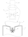
図1を参照して、本実施例に係る液体供給装置について説明する。図1は本発明の実施例に係る液体供給装置の簡略図であり、正面から見た外観図と、外観図中の楕円で囲った部分の内部における要部の構成を簡略的に示す断面図とを示している。
<Liquid supply device>
With reference to FIG. 1, a liquid supply device according to this embodiment will be described. FIG. 1 is a simplified diagram of a liquid supply device according to an embodiment of the present invention, including an external view as seen from the front and a cross-sectional view that simply shows the configuration of the main parts inside the part surrounded by an ellipse in the external view. It shows.
液体供給装置は、液体供給装置本体10と、液体供給装置本体10に着脱自在に設けられる容器20とから構成される。液体供給装置本体10は、冷水用の第1の注口11aと、第1の注口11aから冷水を注ぎ出すための第1のレバー12aと、温水用の第2の注口11bと、第2の注口11bから温水を注ぎ出すための第2のレバー12bとを備えている。また、液体供給装置本体10は、容器20が装着された際に容器20を支持するための容器受け13を備えている。容器20は、液体(本実施例では水)が収容される容器本体21と、容器本体21の液体供給口を塞ぐキャップ200とを備えている。
The liquid supply device includes a liquid supply device
以下の説明において、液体供給装置本体10に関する構成の上下方向については、液体供給装置本体10が水平面に載置された状態における上下方向を意味する。また、容器20に関する上下方向については、容器20が水平面に載置された状態(容器本体21におけるキャップ200が取り付けられる側とは反対側の底面が水平面に載置された状態)における上下方向を意味する。なお、容器20が液体供給装置本体10に装着される過程、及び装着された後の状態においては、容器本体21に対してキャップ200が下側となる。
In the following description, the vertical direction of the configuration regarding the liquid supply device
ここで、液体供給装置本体10においては、容器受け13の底から上方に突出する軸部材100が設けられている。この軸部材100について、特に、図2を参照して説明する。図2は本発明の実施例に係る軸部材の一例を示す外観図である。なお、図2(a)と同図(b)においては、各部の形状や寸法が異なるだけで基本的な構成及び作用(機能)は同一であるので、基本的な構成が同一の部分には同一の符号を付している。
Here, in the liquid supply device
軸部材100は、軸本体部110と、軸本体部110の上面となる段差面112と、段差面112よりも先端の先細り部120とを有している。なお、先細り部120は、軸本体部110よりも細い部分であることを意味しており、必ずしも、先端に向かって細くなるように構成される必要はない。軸本体部110は内部が中空の筒状の部分であり、軸本体部110には筒内に通じる流入口111が設けられている。これにより、流入口111から流入した液体は、軸本体部110の筒内を通って、液体供給装置本体10の内部へと供給される(図1の断面図中の矢印参照)。軸本体部110の外周面は、上方から下方に向かって徐々に拡径するテーパ面により形成されている。また、軸部材100においては、軸本体部110と先細り部120との間に環状溝130が設けられている。
The
軸部材100については、液体供給装置本体10を製造するメーカーや製品によって、形状や寸法が様々である。すなわち、先細り部120の形状は、図2(a)に示すように、円柱形状の先端の周囲が湾曲面で構成された形状や、図2(b)に示すように長球の一部を切り取ったような形状など、各種の形状を採用し得る。そして、先細り部120の高さH1や環状溝130の溝幅H2も様々である。図2中の点線で示すように、先細り部120の先端に更に細い突起物121を有する構成も採用し得る。また、流入口111についても、その形状及び寸法は様々であり、流入口111の数や配置も様々である。
The shape and dimensions of the
<キャップ>
図3及び図4を参照してキャップ200の構成について、より詳細に説明する。図3は本発明の実施例に係るキャップ200の外観図であり、同図(a)はキャップ200の平面図であり、同図(b)はキャップ200の正面図である。図4は本発明の実施例に係るキャップの模式的断面図であり、図3(a)中のAA断面図に相当する。なお、図4においては、キャップ200が容器本体21の液体供給口21aを塞いだ状態において、液体供給口21aの外形の一部を太い点線にて示している。
<Cap>
The structure of the
キャップ200は、キャップ本体210と、補助キャップ220と、キャップ本体210と補助キャップ220とを繋ぐ薄肉部分230とを備えており、未使用時においては、これらが一体となっている。
The
キャップ本体210は、開口部211aを有する天面211と、天面211より垂下し、液体供給口21aに取り付けられる第1の筒状部212と、第1の筒状部212の筒内において開口部211aより垂下するように設けられる第2の筒状部213とを有する。また、キャップ本体210は、第1の筒状部212の筒内、かつ第2の筒状部213の筒の外側に第3の筒状部214も有している。これら第1から第3の筒状部212,213,214はいずれも略円筒形状である。
The
未使用時、かつ、キャップ200によって容器本体21の液体供給口21aを塞いだ状態においては、略円筒形状の液体供給口21aは、第1の筒状部212と第3の筒状部214との間の環状隙間に差し込まれた状態となっている。これにより、液体供給口21aの外周面と第1の筒状部212の内周面とが密着し、かつ液体供給口21aの内周面と第3の筒状部214の外周面とが密着する。従って、ゴム製のガスケットなどを設けなくても、キャップ200と容器本体21の液体供給口21aとの間からの液体漏れを十分に抑制することができる。
When not in use and when the
そして、第2の筒状部213の内周面には、第1の環状突起213aと第2の環状突起213bが設けられている。特に、第1の環状突起213aは、液体供給装置本体10に容器20が装着された状態において、キャップ本体210と軸部材100との間の環状隙間からの液体の漏れを抑制するための環状のシール突起として機能する。
A first
補助キャップ220は、キャップ本体210における第2の筒状部213における端部の開口部を塞ぐ、有底筒状の部材である。すなわち、補助キャップ220は第2の筒状部213と接続する筒状部分221と、筒状部分221における下端に設けられる底部222とを備えている。つまり、筒状部分221の下端部は底部222により閉塞されている。この補助キャップ220の筒状部分221の上端部には、周方向の少なくとも一部に突起224が設けられている。より具体的には、補助キャップ220における筒状部分221は円筒形状であり、突起224は、筒状部分221の端部221aにおける周方向の120°未満の範囲に複数設けられている。図3(a)においては、角度B(約90°)の範囲に4つの突起224が設けられる例を示している。ただし、突起224は周方向の120°未満の範囲に設けられればよく、その個数も適宜設定することができる。
The
また、補助キャップ220における筒状部分221の内周面には、底部222とは反対側の端部に環状の係合突起223が設けられている。また、補助キャップ220の筒状部分221の外周面には、底部222側が細くなるように構成される段差面221bが設けられている。
Furthermore, an
<キャップの動作メカニズム>
図5から図8を参照して、液体供給装置本体10に対して、容器20を着脱する際のキャップ200の動作メカニズムについて説明する。図5から図8は本発明の実施例に係るキャップのメカニズム説明図である。これらの図においては、キャップ200の構成については模式的断面図にて示しており、容器本体21については省略している。また、軸部材100については外観にて示している。
<Cap operation mechanism>
The operating mechanism of the
液体供給装置本体10に対して、容器20を装着する際においては、容器受け13の上方から容器20を載せるようにすることで、容器20は装着される。図5(a)は装着過程の初期時の様子を示しており、キャップ200が軸部材100の先端に届いていない状態を示している。そして、容器20を更に下方に移動させることで、軸部材100の先細り部120が補助キャップ220内に入り込み、軸本体部110の段差面112が補助キャップ220における筒状部分221の端部221aに突き当たる。本実施例においては、筒状部分221の端部221aに複数の突起224が設けられているため、これらの突起224の少なくとも一つ以上が端部221aに突き当たり、補助キャップ220は軸本体部110の段差面112から偏荷重を受ける。これにより、図5(b)に示すように、補助キャップ220はキャップ本体210から傾くような力Rを受ける。
When mounting the
そして、容器20を更に下方に移動させることで、補助キャップ220における筒状部分の端部221aが軸部材100の段差面112に更に押圧されて、薄肉部分230は突起224が設けられている付近から徐々に破断される。薄肉部分230の全周が破断されることにより、補助キャップ220は第2の筒状部213から離脱する。
Then, by moving the
図6(a)は補助キャップ220がキャップ本体210から離脱した後の状態を示している。キャップ本体210から離脱した補助キャップ220は、筒状部分221の内周面に設けられた係合突起223が、軸部材100における段差面112と先細り部120との間に設けられた環状溝130に係合する。これにより、補助キャップ220は、軸部材100における先細り部120に保持された状態となる。また、容器本体21の容器受け
13への装着過程においては、環状のシール突起である第1の環状突起213aが、軸部材100における軸本体部110の外周面に対して摺動する。そして、装着が完了した状態においては、第1の環状突起213aは軸部材100における軸本体部110の外周面に設けられた環状溝140に嵌る。図6(b)は容器20の装着が完了した際のキャップ200の状態を示している。なお、軸部材100における軸本体部110の外周面は、上方から下方に向かって徐々に拡径するテーパ面により形成されている。そのため、容器20の装着作業は円滑に行われると共に、第1の環状突起213aによる軸本体部110の外周面に対する密着力は装着過程で徐々に高まり、装着完了状態において、シール性が十分に発揮される。
FIG. 6A shows the state after the
次に、容器20を液体供給装置本体10から離脱させる際のキャップ200の動作メカニズムについて説明する。液体供給装置本体10から容器20を離脱する際においては、容器20が上方に持ち上げられる。図7(a)は容器20を上方に持ち上げる過程で、キャップ本体210における第2の筒状部213の端部が、補助キャップ220における筒状部分221の端部を通り過ぎる直前のキャップ200の様子を示している。また、同図(b)は更に容器20を持ち上げた時点のキャップ200の様子を示している。
Next, the operating mechanism of the
本実施例においては、容器受け13から容器本体21を離脱させる過程で、軸部材100の先端に嵌った状態の補助キャップ220は、筒状部分221の上端部がシール突起(第1の環状突起213a)に突き当たるまで第2の筒状部213の内部に入り込む。なお、本実施例においては、筒状部分221の端部(先端部)の外周面全周に面取りが形成され、かつ第2の筒状部213の端部(先端部)の内周面全周に面取りが形成されている。これにより、より確実に、筒状部分221を第2の筒状部213の内部に入り込ませることができる。そして、筒状部分221の上端部がシール突起(第1の環状突起213a)に突き当たるまで第2の筒状部213の内部に入り込み、更に、容器20が持ち上げられることで、補助キャップ220は軸部材100から離脱する。そして、筒状部分221の外周面と第2の筒状部213の内周面との間の環状隙間が封止される。なお、本実施例においては、筒状部分221の上端部が第1の環状突起213aに突き当たるまで第2の筒状部213の内部に入り込んだ状態においては、筒状部分221の段差面221bと第2の筒状部213における第2の環状突起213bが接した状態となる。これにより、より効果的にシール性を高めることができる。図8は容器20を液体供給装置本体10から離脱させた後のキャップ200の状態を示している。このように、容器20を離脱させた状態においても、キャップ本体210と補助キャップ220との間の環状隙間が封止されるため、容器本体21に液体が残っていても、液体が外部に漏れてしまうことを抑制することができる。
In this embodiment, in the process of detaching the
<本実施例に係るキャップの優れた点>
本実施例に係るキャップ200によれば、補助キャップ220における筒状部分221の端部221aが軸部材100の段差面112に押圧されて、補助キャップ220が第2の筒状部213から離脱するように構成されている。そのため、軸部材100における先細り部120の寸法形状に関係なく、補助キャップ220をキャップ本体210から離脱させることができる。従って、様々な液体供給装置本体10に対して、キャップ200を適用することが可能となる。以上より、キャップ200の汎用性を高めることができる。
<Excellent points of the cap according to this example>
According to the
そして、本実施例においては、補助キャップ220における筒状部分221の端部221aに突起224を設けることによって、補助キャップ220は軸本体部110の段差面112から偏荷重を受ける。これにより、補助キャップ220をキャップ本体210から離脱させるのに必要な力を軽減させることができる。なお、上記の通り、軸部材100については、液体供給装置本体10を製造するメーカーや製品によって、形状や寸法が様々であり、軸本体部110に設けられる流入口111の数や配置も様々である。そして、流
入口111の配置によっては、軸本体部110の段差面112が全周に亘って設けられない場合がある。突起224を一つしか設けない場合には、段差面112が設けられていない位置に突起224が入り込むと、段差面112に突起224が当たらずに、補助キャップ220に偏荷重が作用しなくなってしまう。そこで、本実施例においては、筒状部分221の端部221aにおける周方向の120°未満の範囲に突起224を複数設けることで、少なくとも一か所の突起224が段差面112に当たるようにしている。これにより、より確実に、補助キャップ220に偏荷重が作用するようにしている。ただし、突起224を一つしか設けない場合であっても、軸本体部110の段差面112が全周に亘って設けられる装置においては、補助キャップ220に偏荷重が作用するため、キャップ200の汎用性は十分高くすることができる。そして、突起224を上記のように複数個所に設ければ、軸本体部110の段差面112が全周に亘って設けられない装置に対しても、補助キャップ220に偏荷重を作用させることができるので、より一層キャップ200の汎用性を高めることができる。
In this embodiment, by providing the
また、本実施例では、未使用時においては、キャップ本体210と補助キャップ220が薄肉部分230を介して一体に設けられている。そして、容器受け13への容器本体21の装着に伴って薄肉部分230が破断されて、補助キャップ220がキャップ本体210から離脱する構成を採用している。このような構成を採用することで、キャップ200を1部品で構成できるためコストを抑制できると共に、補助キャップ220がキャップ本体210から離脱する前の状態においては、キャップ本体210と補助キャップ220との間に隙間が生じることもない。なお、キャップ本体210と補助キャップ220と薄肉部分230とを一体に有するキャップ200は、金型による樹脂成形により得ることができる。
Further, in this embodiment, when not in use, the cap
また、本実施例においては、補助キャップ220における筒状部分221の内周面には、軸部材100における段差面112と先細り部120との間に設けられた環状溝130に係合する係合突起223が設けられている。これにより、補助キャップ220がキャップ本体210から離脱した状態において、補助キャップ220を軸部材100における先細り部120に安定的に保持させることができる。
In this embodiment, the inner peripheral surface of the
また、本実施例においては、容器本体21の容器受け13への装着過程において軸部材100の外周面に対して摺動し、かつ、装着が完了した状態においては軸部材100の外周面に設けられた環状溝140に嵌る環状の第1の環状突起213aが設けられている。これにより、容器受け13への容器20の装着途中の段階、及び装着後においても、キャップ本体210と軸部材100との間の隙間から液体が漏れてしまうことを抑制することができる。
In addition, in this embodiment, the container
更に、本実施例においては、容器受け13から容器本体21を離脱させる過程で、軸部材100の先端に嵌った状態の補助キャップ220は、筒状部分221の上端部が第1の環状突起213aに突き当たるまで第2の筒状部213の内部に入り込む。そして、補助キャップ220は軸部材100から離脱して、筒状部分221の外周面と第2の筒状部213の内周面との間の環状隙間が封止される。これにより、容器20に液体が残っている状態で、容器20を容器受け13から離脱させても、容器内の液体が漏れてしまうことを抑制することができる。
Furthermore, in this embodiment, in the process of detaching the
(その他)
上記実施例においては、未使用時において、キャップ本体210と補助キャップ220と薄肉部分230とを一体に有するキャップ200を採用した場合について示した。しかしながら、例えば、図9に示すように、未使用時において、キャップ本体210Aと補助キャップ220Aが別体に構成されて、補助キャップ220Aがキャップ本体210Aに
対して圧入により嵌合されるキャップ200Aを採用することもできる。このような構成を採用した場合でも、上記実施例と同様の効果を得ることができる。
(others)
In the above embodiment, a case is shown in which a
また、このキャップ200Aのように、上記実施例で示した第3の筒状部214を有しない構成を採用してもよい。ただし、この構成を採用した場合には、液体供給口21aの外周面と第1の筒状部212の内周面とを密着させるだけでは十分なシール性を得られないこともある。その場合にはゴム製のガスケット250を天面211に貼り付けるように設ける構成を採用するとよい。
Further, like this
10…液体供給装置本体
11a…第1の注口 11b…第2の注口
12a…第1のレバー 12b…第2のレバー
20 容器
21…容器本体 21a…液体供給口
100 軸部材
110…軸本体部
111…流入口 112…段差面
120…先細り部
121…突起物
130…環状溝
140…環状溝
200,200A…キャップ
210…キャップ本体
211…天面 211a…開口部 212…第1の筒状部 213…第2の筒状部
213a…第1の環状突起 213b…第2の環状突起 214…第3の筒状部
220,220A 補助キャップ
221…筒状部分 221a…端部 221b…段差面 222…底部 223…係合突起 224…突起
230…薄肉部分
250…ガスケット
DESCRIPTION OF
Claims (6)
開口部を有する天面と、前記天面より垂下し、前記液体供給口に取り付けられる第1の筒状部と、前記第1の筒状部の筒内において前記開口部より垂下するように設けられる第2の筒状部と、を有するキャップ本体と、
前記第2の筒状部における下端部を塞ぐ補助キャップと、
を備えると共に、
前記補助キャップは前記第2の筒状部と接続する筒状部分を有し、かつ、前記筒状部分の下端部は閉塞されており、
前記容器受けに前記容器本体が装着されることで、前記補助キャップにおける上端部が前記軸部材の前記段差面に押圧されて、前記補助キャップが前記第2の筒状部から離脱するように構成され、かつ、前記上端部には、周方向の少なくとも一部に突起が設けられていることを特徴とするキャップ。 Liquid supply of a container main body that is detachable from the container receiver in a liquid supply device main body that has a step surface and a tapered portion at the tip than the step surface, and a shaft member that projects upward from the bottom of the container receiver. A cap that closes the mouth,
a top surface having an opening; a first cylindrical portion that hangs down from the top surface and is attached to the liquid supply port; a cap body having a second cylindrical part;
an auxiliary cap that closes a lower end of the second cylindrical part;
In addition to providing
The auxiliary cap has a cylindrical part connected to the second cylindrical part, and a lower end of the cylindrical part is closed,
When the container body is attached to the container receiver, the upper end portion of the auxiliary cap is pressed against the stepped surface of the shaft member, and the auxiliary cap is detached from the second cylindrical portion. A cap characterized in that the upper end portion is provided with a protrusion in at least a portion of the circumferential direction.
Priority Applications (1)
| Application Number | Priority Date | Filing Date | Title |
|---|---|---|---|
| JP2022085984A JP2023173615A (en) | 2022-05-26 | 2022-05-26 | cap |
Applications Claiming Priority (1)
| Application Number | Priority Date | Filing Date | Title |
|---|---|---|---|
| JP2022085984A JP2023173615A (en) | 2022-05-26 | 2022-05-26 | cap |
Publications (1)
| Publication Number | Publication Date |
|---|---|
| JP2023173615A true JP2023173615A (en) | 2023-12-07 |
Family
ID=89030471
Family Applications (1)
| Application Number | Title | Priority Date | Filing Date |
|---|---|---|---|
| JP2022085984A Pending JP2023173615A (en) | 2022-05-26 | 2022-05-26 | cap |
Country Status (1)
| Country | Link |
|---|---|
| JP (1) | JP2023173615A (en) |
Citations (3)
| Publication number | Priority date | Publication date | Assignee | Title |
|---|---|---|---|---|
| WO2014170214A1 (en) * | 2013-04-15 | 2014-10-23 | Tetra Laval Holdings & Finance S.A. | Method for manufacturing a closure / stopper for closing the neck of a container, method for closing / stoppering a container using a closure / stopper manufactured according to such a method and a closure / stopper manufactured according to such a method |
| JP6600520B2 (en) * | 2015-09-29 | 2019-10-30 | 日本クロージャー株式会社 | Plastic container lid |
| JP2022023727A (en) * | 2020-07-27 | 2022-02-08 | 康洋 河島 | Integral type cap for bottle |
-
2022
- 2022-05-26 JP JP2022085984A patent/JP2023173615A/en active Pending
Patent Citations (3)
| Publication number | Priority date | Publication date | Assignee | Title |
|---|---|---|---|---|
| WO2014170214A1 (en) * | 2013-04-15 | 2014-10-23 | Tetra Laval Holdings & Finance S.A. | Method for manufacturing a closure / stopper for closing the neck of a container, method for closing / stoppering a container using a closure / stopper manufactured according to such a method and a closure / stopper manufactured according to such a method |
| JP6600520B2 (en) * | 2015-09-29 | 2019-10-30 | 日本クロージャー株式会社 | Plastic container lid |
| JP2022023727A (en) * | 2020-07-27 | 2022-02-08 | 康洋 河島 | Integral type cap for bottle |
Similar Documents
| Publication | Publication Date | Title |
|---|---|---|
| KR102209126B1 (en) | Spray bottle | |
| US3809275A (en) | Stopper | |
| CN101437728B (en) | Self-closing valve with valve cover | |
| WO2013047419A1 (en) | Cap unit for puncture repair | |
| JP5450263B2 (en) | Dispensing container | |
| JP2023173615A (en) | cap | |
| CN104555048A (en) | Bottle cap discharging water through stirring | |
| KR20120125059A (en) | Container of seperately keeping two kinds of liquids from each other | |
| CN110352166A (en) | The sealing structure of lid | |
| JP2012030864A (en) | Discharge vessel | |
| US2797836A (en) | Nipple carrying vent controlling ring | |
| JP6602088B2 (en) | cap | |
| JP5150398B2 (en) | cap | |
| CN105292726A (en) | Elastic self-sealing water outlet structure | |
| CN214016997U (en) | Sealed leak-proof container cover capable of being opened quickly and safely | |
| CN223836187U (en) | Novel leakage-proof cover structure for steel drum | |
| JPH0219437Y2 (en) | ||
| CN213911378U (en) | Medicine water bottle gland structure | |
| CN205649379U (en) | Soybean milk machine | |
| CN221437522U (en) | Ink bottle | |
| JP2013049432A (en) | Spouting tool with check valve, and cap therefor | |
| CN223433263U (en) | Filling valve and filling machine | |
| JP7300933B2 (en) | cap | |
| CN215605224U (en) | Novel oil filtering bottle | |
| JPS5843598Y2 (en) | filling equipment |
Legal Events
| Date | Code | Title | Description |
|---|---|---|---|
| A625 | Written request for application examination (by other person) |
Free format text: JAPANESE INTERMEDIATE CODE: A625 Effective date: 20250414 |
|
| A977 | Report on retrieval |
Free format text: JAPANESE INTERMEDIATE CODE: A971007 Effective date: 20260121 |
|
| A131 | Notification of reasons for refusal |
Free format text: JAPANESE INTERMEDIATE CODE: A131 Effective date: 20260127 |
|
| A521 | Request for written amendment filed |
Free format text: JAPANESE INTERMEDIATE CODE: A523 Effective date: 20260316 |