JP2023072562A - Motor control method and motor control device - Google Patents
Motor control method and motor control device Download PDFInfo
- Publication number
- JP2023072562A JP2023072562A JP2021185198A JP2021185198A JP2023072562A JP 2023072562 A JP2023072562 A JP 2023072562A JP 2021185198 A JP2021185198 A JP 2021185198A JP 2021185198 A JP2021185198 A JP 2021185198A JP 2023072562 A JP2023072562 A JP 2023072562A
- Authority
- JP
- Japan
- Prior art keywords
- feedback signal
- motor control
- command value
- control method
- voltage phase
- Prior art date
- Legal status (The legal status is an assumption and is not a legal conclusion. Google has not performed a legal analysis and makes no representation as to the accuracy of the status listed.)
- Granted
Links
Images


Landscapes
- Control Of Ac Motors In General (AREA)
Abstract
Description
本発明は、電動機制御方法及び電動機制御装置に関する。 The present invention relates to a motor control method and a motor control device.
特許文献1では、三相の巻線組をステータに2組有し、各巻線組は異なる中性点をもつ電動機に対し、2組のステータ巻線に発生する電力を各巻線組に個別に接続されたインバータでフィードバック制御する電動機制御方法が提案されている。特に、この電動機制御方法では、電気的に接続されていない2組の巻線間の磁気結合よって発生する干渉電圧の影響を非干渉化しつつ所望の電力を実現するための電力フィードバック制御を実行する。
In
特に、特許文献1の電動機制御方法では、モータの低回転領域(特に、弱め界磁制御領域などの正弦波電圧を印加すべき回転数域に至らない回転数領域)において、各巻線組の電力フィードバック制御器の出力として少なくとも一つとして当該巻線組の電圧位相を出力し、もう一つとして第1及び第2の巻線組の電圧位相の差分を出力する。
In particular, in the electric motor control method of
しかしながら、特許文献1の電動機制御方法は、第1及び第2の巻線組のそれぞれに対して独立にフィードバック制御器を持つ構成を前提とする。このため、各巻線組のフィードバック信号にリプル成分が残っている場合には、ステータの巻線構造に起因する振動の影響が大きくなって、各巻線組の制御器の出力信号が振動してトルクリプルが引き起こされるという問題がある。
However, the motor control method of
このような事情に鑑み、本発明は、2つの巻線組をもつ多重巻線同期型の電動機において、トルクリプルの発生をより確実に抑制し得る電動機制御方法及び電動機制御装置を提供することを目的とする。 In view of such circumstances, it is an object of the present invention to provide a motor control method and a motor control apparatus capable of more reliably suppressing the occurrence of torque ripple in a multi-winding synchronous motor having two winding sets. and
本発明のある態様によれば、ステータに2つの巻線組が設けられた多重巻線同期型の電動機を制御する電動機制御方法が提供される。この電動機制御方法は、電動機の出力に応じたフィードバック信号を生成する生成工程と、電動機に対する要求出力及びフィードバック信号に基づいて、第1の巻線組に対する電圧位相の指令値である第1電圧位相指令値、及び第2の巻線組に対する電圧位相の指令値である第2電圧位相指令値を演算する演算工程と、を備える。特に、演算工程では、フィードバック信号に対してステータの巻線構造に起因する電気角逓倍次数の振動成分を除去する振動除去処理を実行することで補正フィードバック信号を生成し、補正フィードバック信号に基づいて、第1電圧位相指令値及び第2電圧位相指令値を演算する。 According to one aspect of the present invention, there is provided a motor control method for controlling a multi-winding synchronous motor having a stator with two winding sets. This motor control method includes a generation step of generating a feedback signal according to the output of the motor, and a first voltage phase command value for the first winding set based on the required output and the feedback signal for the motor. and a computing step of computing a command value and a second voltage phase command value, which is a voltage phase command value for the second winding set. In particular, in the calculation process, a correction feedback signal is generated by performing vibration removal processing for removing the vibration component of the multiplied electrical angle due to the winding structure of the stator on the feedback signal, and based on the correction feedback signal, , a first voltage phase command value and a second voltage phase command value are calculated.
本発明によれば、2つの巻線組をもつ多重巻線同期モータにおいて、トルクリプルの発生をより確実に抑制することができる。 According to the present invention, it is possible to more reliably suppress the occurrence of torque ripple in a multiple winding synchronous motor having two winding sets.
以下、本発明の実施形態について説明する。 Embodiments of the present invention will be described below.
(第1実施形態)
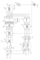
図1は、本実施形態による電動機制御方法を実行するための電動機制御システム100の構成を説明するブロック図である。また、図2は、電動機制御方法の処理の概要を説明するフローチャートである。
(First embodiment)
FIG. 1 is a block diagram illustrating the configuration of a motor control system 100 for executing the motor control method according to this embodiment. Also, FIG. 2 is a flowchart for explaining the outline of the processing of the motor control method.
本実施形態の電動機制御システム100は、固定子(ステータ)に2組の巻線組が設けられた多重巻線同期電動機(より詳細には三相二重巻線型の永久磁石同期モータ)としてのモータ101の動作を制御するシステムである。
The motor control system 100 of the present embodiment is a multiple-winding synchronous motor (more specifically, a three-phase double-winding permanent-magnet synchronous motor) in which two sets of windings are provided on a stator. It is a system that controls the operation of the
モータ101は、種々の駆動力要求装置の動力源として用いることができる。特に、モータ101は、電気自動車(EV)又はハイブリッド自動車(HEV)等の電動モータの駆動力で走行する任意の車両における駆動源として用いられる。
The
ここで、本実施形態における巻線組とは、各相(例えば、三相交流の場合、U相、V相、及びW相の各相)のそれぞれに対応する一組の巻線を組み合わせて成る巻線組を意味する。 Here, the winding set in the present embodiment is a combination of a set of windings corresponding to each phase (for example, each phase of U phase, V phase, and W phase in the case of three-phase alternating current). means a set of windings consisting of
また、以下の説明において、上記複数の巻線組の内の特定の巻線組への通電を制御する一組の構成要素の単位を「系統」と称する。 Further, in the following description, a unit of a set of components for controlling energization of a specific winding set among the plurality of winding sets is referred to as a "system".
さらに、以下の説明においては、三相二重巻線型永久磁石同期モータとして構成されるモータ101を備える電動機制御システム100において、上述した2つの系統をそれぞれ「系統1」及び「系統2」と称する。特に、系統1における各制御量(電流など)及び系統2における各制御量を区別する必要がある場合には、これら各制御量に「1」又は「2」という下付きの添え字を付する。
Furthermore, in the following description, in the electric motor control system 100 including the
また、これら系統1及び系統2における各制御量を包括して説明する場合には、各制御量に「n」(n=1又は2)という下付きの添え字を付する。例えば、系統1における三相電圧の指令値「三相電圧指令値(v*
u1,v*
v1,v*
w1)」及び系統2における三相電圧の指令値「三相電圧指令値(v*
u2,v*
v2,v*
w2)」を包括して、「三相電圧指令値(v*
un,v*
vn,v*
wn)」などと表記する。
Further, when each control amount in
図1に示すように、本実施形態の電動機制御システム100は、PWM変換器102と、三相電圧型のインバータ103と、直流電源104と、電流センサ105と、A/D変換器106と、3相/dq交流座標変換部107と、磁極位置検出器108と、パルスカウンタ109と、角速度演算部110と、トルク推定部111と、トルク制御部112と、電圧指令値演算部113と、dq/3相交流座標変換器114と、振動除去部115と、を有している。なお、これらの各構成の機能は、適宜、当該機能を実行するようにプログラムされたコンピュータにより実現される。
As shown in FIG. 1, the motor control system 100 of this embodiment includes a
PWM変換器102は、2系統の三相電圧指令値(v*
un,v*
vn,v*
wn)に基づいて、2系統の三相電圧型のインバータ103のスイッチング素子(IGBTなど)のPWM_Duty駆動信号(D*
uun,D*
uln,D*
vun,D*
vln,D*
wun,D*
wln)を生成する。
The
インバータ103は、PWM変換器102によって生成されるPWM_Duty駆動信号(D*
uun,D*
uln,D*
vun,D*
vln,D*
wun,D*
wln)に基づいて、直流電源104からの直流電圧を三相電圧指令値(v*
un,v*
vn,v*
wn)に応じた三相交流電圧(vun,vvn,vwn)に変換し、モータ101に供給する。
直流電源104は、積層型リチウムイオンバッテリなどの蓄電デバイスにより構成される。
The
電流センサ105は、インバータ103からモータ101の各巻線組に供給される三相交流電流(iun,ivn,iwn)を検出する(図2のステップS10)。特に、電流センサ105は、系統1及び2のそれぞれにおける少なくとも2相の電流(例えば、iu1、iv1、iu2、iv2)を検出する複数(図1では4つ)の個別センサにより構成される。なお、電流センサ105が2相の電流を検出する構成である場合、残りの1相の電流iwnは、次式(1)により求めることができる。

A/D変換器106は、電流センサ105による三相交流電流検出値をデジタル信号に変換して、3相/dq交流座標変換部107に出力する。
A/
磁極位置検出器108は、モータ101の回転子位置に応じたA相B相Z相のパルスをパルスカウンタ109に出力する。
The magnetic
パルスカウンタ109は、磁極位置検出器108からのA相B相Z相のパルスに基づいて、モータ101の電気角度θreを演算する(ステップS10)。この電気角度θreは、実際の機械角度θrm及びモータ101の構造により定まるモータ極対数pに基づいて定まる、モータ101の電気角の実値に相当する値である。
The
角速度演算部110は、パルスカウンタ109からの電気角度θreを時間変化率(時間微分)から電気角速度ωreを演算し、さらに電気角速度ωreをモータ極対数pで除して機械角速度ωrmを演算する(ステップS20)。
3相/dq交流座標変換部107は、パルスカウンタ109で演算される電気角度θreを用いて、A/D変換器106でデジタル信号に変換された三相交流電流検出値(iuns,ivns,iwns)に対して3相交流座標系(uvw軸)から直交2軸直流座標系(dq軸)への変換を行う(ステップS30)。
The three-phase/dq AC
より具体的に、3相/dq交流座標変換部107は、以下の式(2)及び式(3)に基づいて電気角度θreから系統nの電気角θnを算出する。
More specifically, the 3-phase/dq AC


なお、式(2)及び式(3)中の「θoffset」は電気角度θreと系統1の位相差を意味する。また、「θ12」は、系統1に対する系統2の位相差を意味する。すなわち「θ12」は、「θ2-θ1」に相当する。
Note that “θ offset ” in equations (2) and (3) means the phase difference between the electrical angle θ re and
さらに、3相/dq交流座標変換部107は、以下の式(4)に基づき、電気角θnを用いて上記三相交流電流検出値(iuns,ivns,iwns)から系統1のdq軸電流(id1,iq1)及び系統2のdq軸電流(id2,iq2)をそれぞれ算出する。
Furthermore, the three-phase/dq AC

なお、以下では、記載の簡略化のため、適宜、電流等のパラメータに関してd軸成分とq軸成分を包括する符号「x」(x=d,q)を用いた表示を行う。例えば、系統1のdq軸電流(id1,iq1)及び系統2のdq軸電流(id2,iq2)について、d軸及びq軸成分と各系統をそれぞれ包括して「dq軸電流ixn」と表記する。
In the following, for the sake of simplification of description, a symbol “x” (x=d, q) encompassing the d-axis component and the q-axis component will be used to indicate parameters such as current as appropriate. For example, regarding the dq-axis currents (i d1 , i q1 ) of
トルク推定部111は、dq軸電流ixnを入力として、推定トルクTestnを演算する。具体的に、トルク推定部111は、予めメモリに記憶されたd軸電流、q軸電流、及びトルクの関係を定めたテーブルデータを参照して、dq軸電流ixnから推定トルクTestnを求める。なお、このテーブルデータは、実機モータに対する計測又は所定のモデル解析の結果に基づいて定めることができる。特に、このモデル解析には、例えば、3D-CAD等の専用ソフトウェアを用いた3次元有限要素解析(3D-FEA)が含まれる。 A torque estimator 111 receives the dq-axis current i xn and calculates an estimated torque T estn . Specifically, the torque estimator 111 obtains the estimated torque Testn from the dq-axis current ixn by referring to table data preliminarily stored in memory that defines the relationship between the d-axis current, the q-axis current, and the torque . . Note that this table data can be determined based on the results of measurement or predetermined model analysis of the actual motor. In particular, this model analysis includes, for example, three-dimensional finite element analysis (3D-FEA) using dedicated software such as 3D-CAD.
より詳細に、本実施形態のトルク推定部111は、第1トルク推定部111-1及び第2トルク推定部111-2により構成される。第1トルク推定部111-1は、系統1のdq軸電流ix1を入力として、系統1の推定トルクTestである第1推定トルクTest1を演算する。一方、第2トルク推定部111-2は、系統2のdq軸電流ix2を入力として、系統2の推定トルクTestである第2推定トルクTest2を演算する。
More specifically, the torque estimator 111 of the present embodiment is composed of a first torque estimator 111-1 and a second torque estimator 111-2. The first torque estimator 111-1 receives the dq-axis current i x1 of the
振動除去部115は、推定トルクTestnを入力として、当該推定トルクTestnに対してステータ巻線構造に起因して発生する電気角逓倍次数の振動成分を除去する処理(振動除去処理)を実行して補正推定トルクTestn_viblessを生成する。
The
より詳細に、振動除去部115は、第1振動除去部115-1及び第2振動除去部115-2により構成される。第1振動除去部115-1は、第1推定トルクTest1から上記振動成分を除去して、系統1の補正推定トルクTest_viblessである第1補正推定トルクTest1_viblessを演算する。一方、第2振動除去部115-2は、第2推定トルクTest2から上記振動成分を除去して、系統2の補正推定トルクTest_viblessである第2補正推定トルクTest2_viblessを演算する(ステップS40)。
More specifically, the
トルク制御部112は、モータ101に対する要求出力に応じたトルク指令値T*
n、及び補正推定トルクTestn_viblessを入力として、以下の式(5)に基づくPI制御によって電圧位相指令値(以下、「fb電圧位相指令値α*
fbn」とも称する)を演算する(ステップS50)。
The

特に、トルク制御部112は、第1トルク制御部112-1及び第2トルク制御部112-2により構成される。第1トルク制御部112-1は、系統1のトルク指令値T*(以下、「第1トルク指令値T*
1」とも称する)及び第1補正推定トルクTest1_viblessに基づいて、系統1のfb電圧位相指令値α*
fbである第1fb電圧位相指令値α*
fb1を求める。一方、第2トルク制御部112-2は、系統2のトルク指令値T*(以下、「第2トルク指令値T*
2」とも称する)及び第2補正推定トルクTest2_viblessに基づいて、系統2のfb電圧位相指令値α*
fbである第2fb電圧位相指令値α*
fb2を求める。
In particular, the
電圧指令値演算部113は、電圧ノルム指令値Va
*、フィードフォワード信号として定められる電圧指令値(以下、「ff電圧位相指令値α*
ff」とも称する)、及びfb電圧位相指令値α*
fbnを入力として、以下の式(6)に基づいて、dq軸電圧指令値v*
xnを演算する(ステップS60)。
Voltage command

なお、上記dq軸電圧指令値v*
xnの演算及び以降の処理においては説明の簡略化のため、電圧ノルム指令値Va
*及びff電圧位相指令値α*
ffが系統1及び2の双方で共通すること、特に、第1トルク指令値T*
1及び第2トルク指令値T*
2が相互に同一であることを前提とする。しかしながら、これに限られず、系統1及び2の間で、トルク指令値T*、電圧ノルム指令値Va
*、及びff電圧位相指令値α*
ffの少なくとも何れかが相互に異なる場合であっても、式(6)に基づくdq軸電圧指令値v*
xnの演算、及び当該演算以降の各処理を同様の制御ロジックにより実現することが可能である。
Note that in the calculation of the dq-axis voltage command values v * xn and the subsequent processing, the voltage norm command value V a * and the ff voltage phase command value α * ff are assumed to be It is assumed in common that, in particular, the first torque command value T * 1 and the second torque command value T * 2 are mutually identical. However, not limited to this, even if at least one of the torque command value T * , the voltage norm command value V a * , and the ff voltage phase command value α * ff differs between the
dq/3相交流座標変換器114は、電気角度θreを用いて、dq軸電圧指令値v*
xnに対して直交2軸直流座標系(dq軸)から3相交流座標系(uvw軸)への変換を行う(ステップS70)。
The dq/three-phase AC coordinate
特に、dq/3相交流座標変換器114は、上記式(2)及び(3)に基づいて電気角度θreから定まる系統nの電気角θnを用いて、以下の式(7)に基づき、三相電圧指令値(v*
un,v*
vn,v*
wn)を求める。
In particular, the dq/3-phase AC coordinate

以上説明した本実施形態の電動機制御方法の構成及びそれによる作用効果について説明する。 The configuration of the motor control method according to the present embodiment described above and the effects thereof will be described.
本実施形態の電動機制御方法は、ステータ(固定子)に2つの巻線組(系統1及び系統2)が設けられた多重巻線同期型の電動機(モータ101)を制御する電動機制御方法が提供される。
The motor control method of the present embodiment provides a motor control method for controlling a multi-winding synchronous motor (motor 101) in which two winding sets (
この電動機制御方法は、モータ101の出力に応じたフィードバック信号(推定トルクTest)を生成する生成工程(トルク推定部111)と、モータ101に対する要求出力(特にトルク指令値T*)及び推定トルクTestnに基づいて、第1の巻線組に対する電圧位相の指令値である第1電圧位相指令値(第1fb電圧位相指令値α*
fb1)、及び第2の巻線組に対する電圧位相の指令値である第2電圧位相指令値(第2fb電圧位相指令値α*
fb2)を演算する演算工程(トルク制御部112)と、を備える。
This electric motor control method includes a generating step (torque estimator 111) for generating a feedback signal (estimated torque Test ) corresponding to the output of the
そして、演算工程では、推定トルクTestnに対してステータの巻線構造に起因する電気角逓倍次数の振動を除去する振動除去処理(振動除去部115)を実行することで補正フィードバック信号(補正推定トルクTestn_vibless)を生成し、補正推定トルクTestn_viblessに基づいて、第1fb電圧位相指令値α* fb1及び第2fb電圧位相指令値α* fb2を演算する。 Then, in the calculation step , a correction feedback signal (correction estimation torque Testn_vibless ), and calculates the first fb voltage phase command value α * fb1 and the second fb voltage phase command value α * fb2 based on the corrected estimated torque Testn_vibless .
このように、振動除去処理を実行することで、電気角逓倍次数の振動成分が除去されたfb電圧位相指令値α*
fbnが定められることとなる。すなわち、モータ101の制御量であるfb電圧位相指令値α*
fbnから不要な振動成分を消失させることができので、モータ101の出力トルクを安定させることができ、トルクリプルの発生を抑制することができる。
By executing the vibration elimination process in this way, the fb voltage phase command value α * fbn from which the vibration component of the electrical angle multiplication order is eliminated is determined. That is, since unnecessary vibration components can be eliminated from the fb voltage phase command value α * fbn , which is the control amount of the
特に、三相二重巻線モータでは、一般的に電気角6次の振動を低減すべく各系統1,2の巻線組の位相差が30°となるように設計される。しかしながら、巻線組ごとにフィードバックループを構成した電圧位相制御を採用する場合、各フィードバック信号(第1推定トルクTest1及び第2推定トルクTest2)が、上記電気角6次の振動の影響を受けることで当該フィードバック信号に基づいて定まる各操作量が振動し、トルクリプルを生じさせる。これに対して、上記振動除去処理を実行することで、かかるトルクリプルを好適に抑制することができる。
In particular, a three-phase double-wound motor is generally designed so that the phase difference between the winding sets of the
さらに、電気角6次の振動に起因するトルクリプルは、モータ101の回転数(例えば、機械角速度ωrm)が所定の閾値以上となる高回転領域において特に顕著となる。この点を考慮して、モータ101の回転数が上記閾値未満の場合(電気角6次の振動による影響が相対的に小さいと推定される場合)には上記振動除去処理を実行せず、モータ101の回転数が閾値以上の場合(電気角6次の振動による影響が相対的に大きいと推定される場合)に上記振動除去処理を実行する制御ロジックを採用しても良い。より詳細には、モータ101の回転数がある一定値未満の場合にいわゆる電流ベクトル制御を実行し、モータ101の回転数が当該一定値以上の場合に電圧位相制御を実行する制御システムにおいて、上記振動除去処理の実行の有無を判断するための回転数閾値を、当該電圧位相制御が実行されている回転数領域内の特定の値に定める制御構成を採用しても良い。
Furthermore, the torque ripple caused by the vibration of the 6th electrical angle becomes particularly noticeable in a high rotation region where the rotation speed (for example, the mechanical angular velocity ω rm ) of the
また、本実施形態の電動機制御方法において、上記フィードバック信号は、第1の巻線組の出力に応じた第1フィードバック信号(第1推定トルクTest1)、及び第2の巻線組の出力に応じた第2フィードバック信号(第2推定トルクTest2)を含む。そして、演算工程では、第1推定トルクTest1及び第2推定トルクTest2から個別に電気角逓倍次数の振動成分を除去して、それぞれに応じた補正第1フィードバック信号(第1補正推定トルクTest1_vibless)及び補正第2フィードバック信号(第2補正推定トルクTest2_vibless)を定め、第1補正推定トルクTest1_vibless及び第2補正推定トルクTest2_viblessのそれぞれに基づいて、第1fb電圧位相指令値α* fb1及び第2fb電圧位相指令値α* fb2を演算する。 Further, in the electric motor control method of the present embodiment, the feedback signal is a first feedback signal (first estimated torque Test1 ) corresponding to the output of the first winding set and the output of the second winding set. It includes a responsive second feedback signal (second estimated torque Test2 ). Then, in the calculation step, the vibration component of the electrical angle multiplication order is individually removed from the first estimated torque Test1 and the second estimated torque Test2 , and a corrected first feedback signal (first corrected estimated torque T est1_vibless ) and a corrected second feedback signal (second corrected estimated torque Test2_vibless ) are determined, and the first fb voltage phase command value α * fb1 is determined based on the first corrected estimated torque Test1_vibless and the second corrected estimated torque Test2_vibless , respectively. and the second fb voltage phase command value α * fb2 .
これにより、巻線組ごとにフィードバックループが構成された電圧位相制御を採用するシステムにおいて、各フィードバック信号のそれぞれから電気角逓倍次数の振動成分を除去し得る制御構成が実現される。 As a result, in a system employing voltage phase control in which a feedback loop is configured for each winding set, a control configuration capable of removing an oscillation component of the electrical angle multiplication order from each feedback signal is realized.
さらに、本実施形態では、上記電動機制御方法の実行に適した電動機制御装置が提供される。 Furthermore, the present embodiment provides a motor control device suitable for executing the above motor control method.
この電動機制御装置は、モータ101の出力に応じたフィードバック信号(推定トルクTest)を生成する生成部(トルク推定部111)と、モータ101に対する要求出力(特にトルク指令値T*)及び推定トルクTestに基づいて、第1の巻線組に対する電圧位相の指令値である第1電圧位相指令値(第1fb電圧位相指令値α*
fb1)、及び第2の巻線組に対する電圧位相の指令値である第2電圧位相指令値(第2fb電圧位相指令値α*
fb2)を演算する演算部(トルク制御部112)と、を備える。
This electric motor control device includes a generator (torque estimator 111 ) that generates a feedback signal (estimated torque Test) corresponding to the output of the
特に、トルク制御部112は、推定トルクTestに対してステータの巻線構造に起因する電気角逓倍次数の振動を除去する振動除去処理(振動除去部115)を実行することで補正フィードバック信号(補正推定トルクTestn_vibless)を生成し、補正推定トルクTestn_viblessに基づいて、第1fb電圧位相指令値α*
fb1及び第2fb電圧位相指令値α*
fb2を演算する。
In particular, the
これにより、本実施形態の電動機制御方法を実行するための好適な電動機制御装置が実現される。 This implements a suitable motor control device for executing the motor control method of the present embodiment.
(第2実施形態)
以下、第2実施形態について説明する。なお、第1実施形態と同様の要素には、同一の符号を付し、その説明を省略する。
(Second embodiment)
A second embodiment will be described below. Elements similar to those of the first embodiment are assigned the same reference numerals, and descriptions thereof are omitted.
図3は、本実施形態による電動機制御方法を実行するための電動機制御システム100の構成を説明するブロック図である。図示のように、本実施形態では、振動除去部115が、ローパスフィルタ(第1ローパスフィルタ及び第2ローパスフィルタ)又は移動平均処理(第1移動平均処理及び第2移動平均処理)により構成される。
FIG. 3 is a block diagram illustrating the configuration of a motor control system 100 for executing the motor control method according to this embodiment. As illustrated, in this embodiment, the
<振動除去部115がローパスフィルタにより構成される場合>
振動除去部115は、以下の式(8)により、補正推定トルクTestn_viblessを演算する。
<When
The

ただし、式中の「τ」は、ローパスフィルタ伝達関数G(s)の時定数、「ωc」はカットオフ周波数をそれぞれ表す。ここで、カットオフ周波数ωc(又は時定数τ)は、電気角逓倍次数の振動周波数、特に高次の高調波成分のみに有効となるように設定することが好ましい。なお、式(8)に示す一次のローパスフィルタに代えて、高次の高調波成分のみに有効となる2次以上のローパスフィルタを採用しても良い。 However, "τ" in the formula represents the time constant of the low-pass filter transfer function G(s), and "ω c " represents the cutoff frequency. Here, the cut-off frequency ω c (or the time constant τ) is preferably set so as to be effective only for the vibration frequency of the electrical angle multiplication order, especially for higher harmonic components. In place of the first-order low-pass filter shown in Equation (8), a second-order or higher-order low-pass filter that is effective only for higher-order harmonic components may be employed.
<振動除去部115が移動平均処理により構成される場合>
振動除去部115は、以下の式(9)及び式(10)により、補正推定トルクTestn_viblessを演算する。
<Case where the
The

ただし、式中の「MAiN(xi)」は移動平均処理関数、「xi」は入力信号(すなわち、第1推定トルクTest1及び第2推定トルクTest2)、「N」は移動平均回数をそれぞれ表す。ここで、移動平均回数Nは、電気角逓倍次数の振動周波数、特に高次の高調波成分のみに有効となるように設定することが好ましい。なお、式(9)及び式(10)に示す累積移動平均に代えて、適宜得られる振動除去性能を考慮して、加重移動平均などの他の平均処理アルゴリズムを採用しても良い。 However, "MA iN (x i )" in the formula is the moving average processing function, "x i " is the input signal (that is, the first estimated torque Test1 and the second estimated torque Test2 ), and "N" is the moving average Each represents the number of times. Here, it is preferable that the moving average frequency N is set so as to be effective only for the vibration frequency of the electrical angle multiplication order, especially for higher harmonic components. Note that, in place of the cumulative moving average shown in Equations (9) and (10), another average processing algorithm such as a weighted moving average may be adopted in consideration of the vibration elimination performance that can be appropriately obtained.
以上説明した本実施形態の電動機制御方法の構成及びそれによる作用効果について説明する。 The configuration of the motor control method according to the present embodiment described above and the effects thereof will be described.
上記振動除去処理(振動除去部115)は、ローパスフィルタ処理又は移動平均化処理を含む。 The vibration removal processing (vibration removal unit 115) includes low-pass filter processing or moving average processing.
これにより、ステータの巻線構造に起因する電気角逓倍次数の振動を除去するためのより具体的な制御構成が実現される。 This realizes a more specific control configuration for removing vibrations of the electrical angle multiplication order caused by the winding structure of the stator.
特に、上記ローパスフィルタ処理のカットオフ周波数ωc又は移動平均化処理の移動平均回数Nを、電気角逓倍次数の振動成分(高次の高調波成分)を選択的に除去し得る所定値以上に定める。 In particular, the cutoff frequency ωc of the low-pass filtering process or the number of moving averages N of the moving averaging process is set to a predetermined value or more that can selectively remove the vibration component of the electrical angle multiplication order (higher harmonic component). stipulate.
これにより、ローパスフィルタ処理又は移動平均化処理に起因するフィードバック信号(推定トルクTestn)の基本波成分の位相遅れを抑制しつつも、当該推定トルクTestnに含まれる電気角逓倍次数の振動成分を除去することができる。 As a result, while suppressing the phase delay of the fundamental wave component of the feedback signal (estimated torque Testn ) due to the low-pass filter processing or moving average processing, the vibration component of the electrical angle multiplication order included in the estimated torque Testn can be removed.
(第3実施形態)
以下、第3実施形態について説明する。なお、第1又は第2実施形態と同様の要素には、同一の符号を付し、その説明を省略する。本実施形態では、第1推定トルクTest1及び第2推定トルクTest2のそれぞれに個別に含まれる電気角逓倍次数の振動成分を個別に推定し、得られた推定値(第1振動成分Test1_vib及び第2振動成分Test2_vib)を、第1推定トルクTest1及び第2推定トルクTest2から減じることで第1補正推定トルクTest1_vibless及び第2補正推定トルクTest2_viblessを求める制御構成が提供される。
(Third embodiment)
A third embodiment will be described below. Elements similar to those in the first or second embodiment are assigned the same reference numerals, and descriptions thereof are omitted. In the present embodiment, the vibration component of the electrical angle multiplication order included in each of the first estimated torque Test1 and the second estimated torque Test2 is separately estimated, and the obtained estimated value (first vibration component Test1_vib and the second vibration component Test2_vib ) from the first estimated torque Test1 and the second estimated torque Test2 to obtain the first corrected estimated torque Test1_vibless and the second corrected estimated torque Test2_vibless . .
図4は、本実施形態による電動機制御方法を実行するための電動機制御システム100の構成を説明するブロック図である。図示のように、本実施形態では、振動除去部115が、バンドパスフィルタ115a(第1バンドパスフィルタ115a-1及び第2バンドパスフィルタ115a-2)と、減算部115b(第1減算部115b-1及び第2減算部115b-2)と、により構成される。
FIG. 4 is a block diagram illustrating the configuration of a motor control system 100 for executing the motor control method according to this embodiment. As illustrated, in the present embodiment, the
振動除去部115は、以下の式(11)~式(13)により、補正推定トルクTestn_viblessを演算する。
The

ただし、式中の「τ」はバンドフィルタ伝達関数F(s)の時定数、「ωc」はカットオフ周波数、「H0」はバンドフィルタゲイン、「Q」は重みづけ係数をそれぞれ表す。ここで、カットオフ周波数ωc(又は時定数τ)は、電気角逓倍次数の振動周波数、特に高次の高調波成分のみに有効となるように設定することが好ましい。なお、式(11)に示すバンドパスフィルタ115aに代えて、抽出対象とする周波数の数に応じた異なるカットオフ周波数ωcを持つフィルタを並列に接続して成るバンドパスフィルタ115aを用いても良い。
In the equation, "τ" represents the time constant of the band filter transfer function F(s), "ω c " represents the cutoff frequency, "H 0 " represents the band filter gain, and "Q" represents the weighting factor. Here, the cut-off frequency ω c (or the time constant τ) is preferably set so as to be effective only for the vibration frequency of the electrical angle multiplication order, especially for higher harmonic components. Instead of the
以上説明した本実施形態の電動機制御方法の構成及びそれによる作用効果について説明する。 The configuration of the motor control method according to the present embodiment described above and the effects thereof will be described.
本実施形態の振動除去処理では、第1推定トルクTest1及び第2推定トルクTest2のそれぞれに個別に含まれる電気角逓倍次数の振動成分としての第1振動成分Test1_vib及び第2振動成分Test2_vibを推定し(式(11))、第1推定トルクTest1及び第1振動成分Test1_vibに基づいて第1補正推定トルクTest1_viblessを生成し(式(12))、第2推定トルクTest2及び第2振動成分Test2_vibに基づいて第2補正推定トルクTest2_viblessを生成する(式(13))。 In the vibration elimination process of the present embodiment, the first vibration component Test1_vib and the second vibration component T as the vibration components of the electrical angle multiplication order individually included in the first estimated torque Test1 and the second estimated torque Test2 , respectively. est2_vib is estimated (equation (11)), the first corrected estimated torque Test1_vibless is generated based on the first estimated torque Test1 and the first vibration component Test1_vib (equation (12)), and the second estimated torque Test2 and a second corrected estimated torque Test2_vibless based on the second vibration component Test2_vib (equation (13)).
これにより、巻線構造に起因する電気角逓倍次数の振動成分を除去するためのより具体的な制御構成が実現される。 This realizes a more specific control configuration for removing the vibration component of the electrical angle multiplication order caused by the winding structure.
特に、第1振動成分Test1_vib及び第2振動成分Test2_vibの演算を、第1推定トルクTest1及び第2推定トルクTest2に対するバンドパスフィルタ処理という簡易な演算ロジックで実現することができる。 In particular, the calculation of the first vibration component Test1_vib and the second vibration component Test2_vib can be realized by simple calculation logic such as band-pass filtering of the first estimated torque Test1 and the second estimated torque Test2 .
(第3実施形態の変形例)
図5は、本変形例による電動機制御方法を実行するための電動機制御システム100の構成を説明するブロック図である。
(Modified example of the third embodiment)
FIG. 5 is a block diagram illustrating the configuration of a motor control system 100 for executing the motor control method according to this modification.
図示のように、本変形例では、振動除去部115が、差分演算部115cと、減算部115b(第1減算部115b-1及び第2減算部115b-2)と、により構成される。
As shown in the figure, in this modification, the
そして、振動除去部115は、以下の式(14)~式(17)により、補正推定トルクTestn_viblessを演算する。
Then, the

このように本変形例では、第1振動成分Test1_vib及び第2振動成分Test2_vibを、第1推定トルクTest1及び第2推定トルクTest2の差分演算という簡易な演算処理により推定することができる。 As described above, in this modified example, the first vibration component Test1_vib and the second vibration component Test2_vib can be estimated by a simple arithmetic process of calculating the difference between the first estimated torque Test1 and the second estimated torque Test2 . .
(第4実施形態)
以下、第4実施形態について説明する。なお、第1~第3実施形態の何れかと同様の要素には、同一の符号を付し、その説明を省略する。本実施形態では、第1推定トルクTest1及び第2推定トルクTest2の何れか一方(以下では、第1推定トルクTest1として説明を行う)に含まれる電気角逓倍次数の振動成分(第1振動成分Test1_vib)を推定し、得られた推定値を、第1推定トルクTest1及び第2推定トルクTest2から減じることで第1補正推定トルクTest1_vibless及び第2補正推定トルクTest2_viblessを求める制御構成が提供される。
(Fourth embodiment)
A fourth embodiment will be described below. Elements that are the same as those in any of the first to third embodiments are given the same reference numerals, and description thereof will be omitted. In the present embodiment , the vibration component of the multiplied electrical angle order (first Estimate the vibration component Test1_vib ), and subtract the obtained estimated value from the first estimated torque Test1 and the second estimated torque Test2 to obtain the first corrected estimated torque Test1_vibless and the second corrected estimated torque Test2_vibless . A control configuration is provided.
図6は、本実施形態による電動機制御方法を実行するための電動機制御システム100の構成を説明するブロック図である。図示のように、本実施形態では、振動除去部115が、第1推定トルクTest1に対するバンドパスフィルタ115aと、減算部115bと、加算部115dと、により構成される。
FIG. 6 is a block diagram illustrating the configuration of a motor control system 100 for executing the motor control method according to this embodiment. As illustrated, in the present embodiment, the
そして、振動除去部115は、以下の式(18)~式(20)により、補正推定トルクTestn_viblessを演算する。
Then, the

以上説明した本実施形態の電動機制御方法の構成及びそれによる作用効果について説明する。 The configuration of the motor control method according to the present embodiment described above and the effects thereof will be described.
本実施形態の振動除去処理では、第1推定トルクTest1及び第2推定トルクTest2の何れか一方(第1推定トルクTest1)に含まれる電気角逓倍次数の振動成分(第1振動成分Test1_vib)を推定し(式(18))、第1推定トルクTest1及び第1振動成分Test1_vibに基づいて第1補正推定トルクTest1_viblessを生成し(式(19))、第2推定トルクTest2及び第1振動成分Test1_vibに基づいて第2補正推定トルクTest2_viblessを生成する(式(20))。 In the vibration elimination process of the present embodiment, the vibration component (the first vibration component T est1_vib ) is estimated (equation (18)), the first corrected estimated torque T est1_vibless is generated based on the first estimated torque T est1 and the first vibration component T est1_vib (equation (19)), and the second estimated torque T A second corrected estimated torque Test2_vibless is generated based on est2 and the first vibration component Test1_vib (equation (20)).
これにより、一方の系統に係るフィードバック信号に含まれる電気角逓倍次数の振動成分のみを推定することで、両系統における第1補正推定トルクTest1_vibless及び第2補正推定トルクTest2_viblessを演算可能となる制御構成が実現される。したがって、演算負担を軽減しつつ、トルクリプルを抑制することができる。特に、電気角逓倍次数の振動成分は、系統間の対称性を考慮すると、両系統の各フィードバック信号に概ね逆符号の同一の波形として含まれる。このため、式(19)及び式(20)のように、推定した第1振動成分Test1_vibを一方の系統に係る第1推定トルクTest1から減じるとともに、他方の系統に係る第2推定トルクTest2に加算することで、実用的な精度が確保されたそれぞれの第1補正推定トルクTest1_vibless及び第2補正推定トルクTest2_viblessを得ることができる。 Thus, by estimating only the vibration component of the electrical angle multiplication order included in the feedback signal related to one system, it is possible to calculate the first corrected estimated torque Test1_vibless and the second corrected estimated torque Test2_vibless in both systems. A control configuration is realized. Therefore, it is possible to suppress the torque ripple while reducing the calculation load. In particular, considering the symmetry between the systems, the vibration component of the multiplied electrical angle order is included in the feedback signals of both systems as the same waveform with substantially opposite signs. Therefore, as shown in equations (19) and (20), the estimated first vibration component Test1_vib is subtracted from the first estimated torque Test1 related to one system, and the second estimated torque T By adding to est2 , it is possible to obtain the first corrected estimated torque Test1_vibless and the second corrected estimated torque Test2_vibless that ensure practical accuracy.
なお、本実施形態では、一方の系統に係るフィードバック信号に含まれる電気角逓倍次数の振動成分として第1振動成分Test1_vibを演算し、これに基づき第1補正推定トルクTest1_vibless及び第2補正推定トルクTest2_viblessを求める例を説明した。一方で、これに代えて、一方の系統に係るフィードバック信号に含まれる電気角逓倍次数の振動成分として第2振動成分Test2_vibを演算し、これに基づき第1補正推定トルクTest1_vibless及び第2補正推定トルクTest2_viblessを求めても良い。この場合においても、系統官間における振動成分の対称性から同様の効果が得られる。 In the present embodiment, the first vibration component Test1_vib is calculated as the vibration component of the electrical angle multiplication order included in the feedback signal related to one system, and based on this, the first corrected estimated torque Test1_vibless and the second corrected estimated torque Test1_vibless are calculated. An example of obtaining the torque Test2_vibless has been described. On the other hand, instead of this, the second vibration component Test2_vib is calculated as the vibration component of the electrical angle multiplication order included in the feedback signal related to one system, and based on this, the first correction estimated torque Test1_vibless and the second correction are calculated. An estimated torque Test2_vibless may be obtained. Also in this case, the same effect can be obtained from the symmetry of the vibration components between the system organs.
(第4実施形態の変形例)
図7は、本変形例による電動機制御方法を実行するための電動機制御システム100の構成を説明するブロック図である。
(Modified example of the fourth embodiment)
FIG. 7 is a block diagram illustrating the configuration of a motor control system 100 for executing the motor control method according to this modification.
図示のように、本変形例では、振動除去部115が、差分演算部115cと、減算部115bと、加算部115dと、により構成される。
As shown in the figure, in this modified example, the
そして、振動除去部115は、以下の式(21)~式(23)により、補正推定トルクTestn_viblessを演算する。
Then, the

このように本変形例では、第1補正推定トルクTest1_vibless及び第2補正推定トルクTest2_viblessを求めるための第1振動成分Test1_vibを、第1推定トルクTest1及び第2推定トルクTest2の差分演算という簡易な演算処理で求めることができ、演算負担がより軽減される。 As described above, in this modification, the first vibration component Test1_vib for obtaining the first corrected estimated torque Test1_vibless and the second corrected estimated torque Test2_vibless is the difference between the first estimated torque Test1 and the second estimated torque Test2 . It can be obtained by a simple arithmetic process called arithmetic, and the arithmetic load is further reduced.
(第5実施形態)
以下、第5実施形態について説明する。なお、第1~第4実施形態の何れかと同様の要素には、同一の符号を付し、その説明を省略する。特に、本実施形態では、予め準備された振動モデルに基づいて、電気角逓倍次数の振動成分(特に、第1振動成分Test1_vib)を推定し、当該第1推定トルクTest1及び第2推定トルクTest2から推定された第1振動成分Test1_vibを除去する制御構成が提供される。
(Fifth embodiment)
The fifth embodiment will be described below. Elements similar to those in any one of the first to fourth embodiments are denoted by the same reference numerals, and description thereof will be omitted. In particular, in this embodiment, based on a vibration model prepared in advance, the vibration component of the multiplied electrical angle order (in particular, the first vibration component T est1_vib ) is estimated, and the first estimated torque T est1 and the second estimated torque A control arrangement is provided that removes the first vibrational component Test1_vib estimated from Test2 .
図8は、本実施形態による電動機制御方法を実行するための電動機制御システム100の構成を説明するブロック図である。図示のように、本実施形態では、振動除去部115が、振動モデルテーブル115eと、減算部115bと、加算部115dと、により構成される。
FIG. 8 is a block diagram illustrating the configuration of a motor control system 100 for executing the motor control method according to this embodiment. As illustrated, in the present embodiment, the
そして、振動除去部115は、第1トルク指令値T*
1、電気角速度ωre、及び電気角度θreを入力信号として、振動モデルテーブル115eを参照して第1振動成分Test1_vibを求める。ここで、振動モデルテーブル115eは、実験、シミュレーション、及び/又はモータ磁気回路特性の解析結果に基づいて予め定められる。
Then, the
さらに、振動除去部115は、第4実施形態と同様に式(19)及び式(20)を用いて、第1振動成分Test1_vib、第1推定トルクTest1、及び第2推定トルクTest2から、第1補正推定トルクTest1_vibless及び第2補正推定トルクTest2_viblessを求める。 Furthermore, the vibration remover 115 uses the equations (19) and ( 20 ) in the same manner as in the fourth embodiment to obtain , the first corrected estimated torque Test1_vibless and the second corrected estimated torque Test2_vibless .
以上説明した本実施形態の電動機制御方法の構成及びそれによる作用効果について説明する。 The configuration of the motor control method according to the present embodiment described above and the effects thereof will be described.
本実施形態の演算工程では、振動除去処理として、予め準備された振動モデルテーブル115eに基づいて、電気角逓倍次数の振動成分(特に、第1振動成分Test1_vib)を推定する。 In the calculation process of the present embodiment, as the vibration removal process, the vibration component of the electrical angle multiplication order (in particular, the first vibration component T est1 — vib ) is estimated based on the vibration model table 115e prepared in advance.
これにより、巻線構造に起因する電気角逓倍次数の振動成分を除去するためのより具体的な制御構成が実現される。 This realizes a more specific control configuration for removing the vibration component of the electrical angle multiplication order caused by the winding structure.
なお、振動モデルテーブル115eの入力信号としては、第1振動成分Test1_vibを求めるという機能を実現し得る範囲において種々変更が可能である。例えば、第1トルク指令値T* 1に代えて系統1の巻線組の実電流(例えば、dq軸電流ix1の検出値など)、及び/又は電気角度θreに代えて機械角速度ωrmを入力信号とする振動モデルテーブル115eを採用しても良い。また、第1振動成分Test1_vibが直流電圧の違いに対して一定の感度を示す場合などには、直流電圧(直流電源104の出力電圧)の検出値を入力信号としても良い。さらに、振動モデルテーブル115eを、複数の振動周波数成分(複数の電気角逓倍次数の振動成分)を除去できるように構成しても良い。 The input signal of the vibration model table 115e can be changed in various ways within the range where the function of obtaining the first vibration component Test1_vib can be realized. For example, instead of the first torque command value T * 1 , the actual current of the winding set of the system 1 (for example, the detected value of the dq-axis current i x1 ), and/or instead of the electrical angle θ re , the mechanical angular velocity ω rm may be adopted as the vibration model table 115e having as an input signal. In addition, when the first vibration component Test1_vib exhibits a certain sensitivity to a difference in DC voltage, the detected value of the DC voltage (the output voltage of the DC power supply 104) may be used as the input signal. Furthermore, the vibration model table 115e may be configured so as to be able to remove a plurality of vibration frequency components (a plurality of vibration components of multiple electrical angle orders).
(第6実施形態)
以下、第6実施形態について説明する。なお、第1~第5実施形態の何れかと同様の要素には、同一の符号を付し、その説明を省略する。
(Sixth embodiment)
The sixth embodiment will be described below. Elements that are the same as those in any of the first to fifth embodiments are given the same reference numerals, and description thereof will be omitted.
特に、本実施形態では、上記振動除去処理として、第1推定トルクTest1及び第2推定トルクTest2を統合した推定合成トルクTest1_sumを生成する。そして、生成した推定合成トルクTest1_sumに基づいて、第1fb電圧位相指令値α* fb1及び第2fb電圧位相指令値α* fb2を演算する。 In particular, in the present embodiment, as the vibration elimination process, an estimated combined torque Test1_sum is generated by integrating the first estimated torque Test1 and the second estimated torque Test2 . Then, the first fb voltage phase command value α * fb1 and the second fb voltage phase command value α * fb2 are calculated based on the generated estimated combined torque Test1_sum .
図9は、本実施形態による電動機制御方法を実行するための電動機制御システム100の構成を説明するブロック図である。図示のように、本実施形態では、振動除去部115が、d軸電流合成部116と、q軸電流合成部117と、推定合成トルク演算部118と、により構成される。
FIG. 9 is a block diagram illustrating the configuration of a motor control system 100 for executing the motor control method according to this embodiment. As shown in the figure, in this embodiment, the
d軸電流合成部116は、3相/dq交流座標変換部107から入力される系統1のd軸電流id1と系統2のd軸電流id2の和を合成d軸電流id_sumとして演算し、推定合成トルク演算部118に出力する。
The d-axis
q軸電流合成部117は、3相/dq交流座標変換部107から入力される系統1のq軸電流iq1と系統2のq軸電流iq2の和を合成q軸電流iq_sumとして演算し、推定合成トルク演算部118に出力する。
The q-axis
推定合成トルク演算部118は、予め定められる電流-トルクマップを参照して、入力された合成d軸電流id_sum及び合成q軸電流iq_sumに基づいて、推定合成トルクTest_sumを求める。なお、電流-トルクマップは、実験又はシミュレーションにより得られる系統1及び2を統合したモータ101の電流-トルク特性に基づいて定められる。
The estimated combined
そして、トルク制御部112は、トルク指令値T*(T*
1+T*
2)及び推定合成トルクTest_sumを入力として、fb電圧位相指令値α*
fbを求める。より具体的には、第1実施形態で示した式(5)に基づき、「α*
fbn」を「α*
fb」、「T*
n」を「T*」、及び「Testn_vibless」を「Test_sum」にそれぞれ置き換えて、fb電圧位相指令値α*
fbを演算する。さらに、トルク制御部112は、得られたfb電圧位相指令値α*
fbにff電圧位相指令値α*
ffを加算して、系統1及び2の共通のfb電圧位相指令値α*
fbとして機能する最終電圧位相指令値α*
finを求める。
そして、電圧指令値演算部113は、電圧ノルム指令値Va
*及び最終電圧位相指令値α*
finを入力として系統間の対称性を考慮し、以下の式(24)に基づき各系統のdq軸電圧指令値v*
xnを定める。

以上説明した本実施形態の電動機制御方法の構成及びそれによる作用効果について説明する。 The configuration of the motor control method according to the present embodiment described above and the effects thereof will be described.
本実施形態の電動機制御方法において、フィードバック信号は、第1の巻線組の出力に応じた第1フィードバック信号(d軸電流id1及びq軸電流iq1)、及び第2の巻線組出力に応じた第2フィードバック信号(d軸電流id2及びq軸電流iq2)を含む。そして、演算工程では、振動除去処理として、第1フィードバック信号及び第2フィードバック信号を統合した統合フィードバック信号(推定合成トルクTest_sum)を生成し、推定合成トルクTest_sumを補正フィードバック信号として、第1fb電圧位相指令値α* fb1及び第2fb電圧位相指令値α* fb2(本実施形態では、何れも最終電圧位相指令値α* fin)を演算する。 In the motor control method of the present embodiment, the feedback signal is a first feedback signal (d-axis current i d1 and q-axis current i q1 ) corresponding to the output of the first winding set, and the second winding set output (d-axis current i d2 and q-axis current i q2 ) in response to . Then, in the calculation step, as vibration elimination processing, an integrated feedback signal (estimated combined torque Test_sum ) is generated by integrating the first feedback signal and the second feedback signal, and the estimated combined torque Test_sum is used as a correction feedback signal, and the first fb A voltage phase command value α * fb1 and a second fb voltage phase command value α * fb2 (in this embodiment, both are final voltage phase command values α * fin ) are calculated.
これにより、制御系を、系統1及び系統2を統括したモータ101の制御に係る一つのフィードバックループにより構成して制御ロジックを簡素化しつつ、上記振動除去処理の機能も実現することができる。
As a result, the control system can be configured by one feedback loop related to the control of the
また、本実施形態の生成工程では、第1の巻線組及び第2の巻線組の各dq軸電流ixnをフィードバック信号として生成する。また、演算工程では、各dq軸電流ixnに基づく推定合成トルクTest_sumを上記統合フィードバック信号として演算する。特に、推定合成トルクTest_sumは、各dq軸電流ixnの内のd軸成分同士の和(id1+id2)として定まる合成d軸電流id_sum、及び各dq軸電流ixnの内のq軸成分同士の和(iq1+iq2)として定まる合成q軸電流iq_sumに基づいて得られる。 Further, in the generation step of the present embodiment, each dq-axis current i xn of the first winding set and the second winding set is generated as a feedback signal. Further, in the calculation step, an estimated combined torque Test_sum based on each dq-axis current ixn is calculated as the integrated feedback signal. In particular, the estimated combined torque Test_sum is the combined d-axis current i d_sum determined as the sum (i d1 +i d2 ) of the d-axis components in each dq-axis current i xn , and q It is obtained based on the combined q-axis current i q_sum determined as the sum of the axis components (i q1 +i q2 ).
これにより、上述した振動除去機能を実現可能な一つのフィードバックループを備えるより具体的な制御構成を実現することができる。 Thereby, it is possible to realize a more specific control configuration having one feedback loop capable of realizing the above-described vibration elimination function.
(第6実施形態の変形例)
図10は、本変形例による電動機制御方法を実行するための電動機制御システム100の構成を説明するブロック図である。
(Modified example of the sixth embodiment)
FIG. 10 is a block diagram illustrating the configuration of a motor control system 100 for executing the motor control method according to this modification.
図示のように、本変形例では、振動除去部115が、推定合成トルク演算部118により構成される。特に、本変形例の推定合成トルク演算部118は、第1トルク推定部111-1で演算された第1推定トルクTest1及び第2トルク推定部111-2で演算された第2推定トルクTest2を入力とし、これらの和を推定合成トルクTest_sumとして求め、トルク制御部112に出力する。
As shown in the figure, in this modified example, the
すなわち、本変形例の生成工程では、第1の巻線組(系統1)及び第2の巻線組(系統2)の各推定トルク(第1推定トルクTest1及び第2推定トルクTest2)をフィードバック信号として生成する。そして、演算工程では、統合フィードバック信号として、第1推定トルクTest1及び第2推定トルクTest2を合成した推定合成トルクTest_sumを演算する。 That is, in the generation process of this modification, each estimated torque (first estimated torque Test1 and second estimated torque Test2 ) of the first winding set (system 1) and the second winding set (system 2 ) is generated as a feedback signal. Then, in the calculation step, an estimated combined torque Test_sum obtained by synthesizing the first estimated torque Test1 and the second estimated torque Test2 is calculated as an integrated feedback signal.
これにより、上述した振動除去機能を実現可能な一つのフィードバックループを備えるより具体的な制御構成を実現することができる。 Thereby, it is possible to realize a more specific control configuration having one feedback loop capable of realizing the above-described vibration elimination function.
以上、本発明の実施形態について説明したが、上記実施形態で説明した構成は本発明の適用例の一部を示したに過ぎず、本発明の技術的範囲を限定する趣旨ではない。 Although the embodiments of the present invention have been described above, the configurations described in the above embodiments merely show a part of application examples of the present invention, and are not intended to limit the technical scope of the present invention.
なお、上記各実施形態では、モータ101の出力に応じたフィードバック信号として、推定トルクTestn又はdq軸電流ixnを採用する例を説明した。しかしながら、フィードバック信号を構成するパラメータはこれに限られず、モータ101の出力の大小に相関する任意のパラメータを採用することができる。例えば、三相交流電流検出値(iuns,ivns,iwns)を適切な次数に変換して得られたパラメータに基づいてフィードバック信号を生成しても良い。
In each of the above-described embodiments, an example in which the estimated torque Testn or the dq-axis current ixn is used as the feedback signal corresponding to the output of the
また、上記各実施形態では、モータ101の要求出力の示唆量としてトルク指令値T*
nを用いてfb電圧位相指令値α*
fbの演算する例について説明した。しかしながら、fb電圧位相指令値α*
fbの演算に用いるパラメータとしては、トルク指令値T*
nに限られず、モータ101の要求出力に相関する任意のパラメータを採用することができる。
Further, in each of the above-described embodiments, an example in which the fb voltage phase command value α * fb is calculated using the torque command value T * n as the suggested amount of the required output of the
100 電動機制御システム、101 モータ、102 PWM変換器、103 インバータ、104 直流電源、105 電流センサ、106 A/D変換器、107 3相/dq交流座標変換部、108 磁極位置検出器、109 パルスカウンタ、110 角速度演算部、111 トルク推定部、112 トルク制御部、113 電圧指令値演算部、114 dq/3相交流座標変換器、115 振動除去部
100 Motor Control System, 101 Motor, 102 PWM Converter, 103 Inverter, 104 DC Power Supply, 105 Current Sensor, 106 A/D Converter, 107 3-Phase/dq AC Coordinate Converter, 108 Magnetic Pole Position Detector, 109 Pulse Counter , 110 angular velocity calculator, 111 torque estimator, 112 torque controller, 113 voltage command value calculator, 114 dq/3-phase AC coordinate converter, 115 vibration remover
Claims (12)
前記電動機の出力に応じたフィードバック信号を生成する生成工程と、
前記電動機に対する要求出力及び前記フィードバック信号に基づいて、第1の前記巻線組に対する電圧位相の指令値である第1電圧位相指令値、及び第2の前記巻線組に対する電圧位相の指令値である第2電圧位相指令値を演算する演算工程と、を備え、
前記演算工程では、
前記フィードバック信号に対して前記ステータの巻線構造に起因する電気角逓倍次数の振動成分を除去する振動除去処理を実行することで補正フィードバック信号を生成し、
前記補正フィードバック信号に基づいて、前記第1電圧位相指令値及び前記第2電圧位相指令値を演算する、
電動機制御方法。 A motor control method for controlling a multi-winding synchronous motor in which a stator is provided with two winding sets,
a generation step of generating a feedback signal according to the output of the electric motor;
A first voltage phase command value, which is a voltage phase command value for the first winding set, and a voltage phase command value for the second winding set, based on the required output for the motor and the feedback signal. a computing step of computing a certain second voltage phase command value,
In the calculation step,
generating a correction feedback signal by performing a vibration removal process on the feedback signal to remove a vibration component of a multiplied electrical angle due to the winding structure of the stator;
calculating the first voltage phase command value and the second voltage phase command value based on the corrected feedback signal;
Electric motor control method.
前記フィードバック信号は、
第1の前記巻線組の出力に応じた第1フィードバック信号、及び第2の前記巻線組の出力に応じた第2フィードバック信号を含み、
前記演算工程では、
前記第1フィードバック信号及び前記第2フィードバック信号から個別に前記電気角逓倍次数の振動成分を除去して、それぞれに応じた補正第1フィードバック信号及び補正第2フィードバック信号を定め、
前記補正第1フィードバック信号及び前記補正第2フィードバック信号のそれぞれに基づいて、前記第1電圧位相指令値及び前記第2電圧位相指令値を演算する、
電動機制御方法。 The electric motor control method according to claim 1,
The feedback signal is
a first feedback signal responsive to the output of the first winding set and a second feedback signal responsive to the output of the second winding set;
In the calculation step,
determining a corrected first feedback signal and a corrected second feedback signal respectively by removing the vibration component of the multiplied electrical angle order from the first feedback signal and the second feedback signal, respectively;
calculating the first voltage phase command value and the second voltage phase command value based on the corrected first feedback signal and the corrected second feedback signal, respectively;
Electric motor control method.
前記振動除去処理は、前記フィードバック信号に対するローパスフィルタ処理又は移動平均化処理を含む、
電動機制御方法。 The motor control method according to claim 1 or 2,
The vibration removal processing includes low-pass filtering or moving average processing for the feedback signal,
Electric motor control method.
前記ローパスフィルタ処理のカットオフ周波数又は前記移動平均化処理の移動平均回数を、前記電気角逓倍次数の振動成分を選択的に除去し得る所定値以上に定める、
電動機制御方法。 The electric motor control method according to claim 3,
setting the cutoff frequency of the low-pass filtering process or the number of moving averages of the moving average process to a predetermined value or more that can selectively remove the vibration component of the multiplied electrical angle order;
Electric motor control method.
前記振動除去処理では、前記第1フィードバック信号及び前記第2フィードバック信号のそれぞれに個別に含まれる前記電気角逓倍次数の振動成分としての第1振動成分及び第2振動成分を推定し、
前記第1フィードバック信号及び前記第1振動成分に基づいて前記補正第1フィードバック信号を生成し、
前記第2フィードバック信号及び前記第2振動成分に基づいて前記補正第2フィードバック信号を生成する、
電動機制御方法。 The electric motor control method according to claim 2,
In the vibration removal process, a first vibration component and a second vibration component as vibration components of the electrical angle multiplication order individually included in the first feedback signal and the second feedback signal are estimated,
generating the corrected first feedback signal based on the first feedback signal and the first vibration component;
generating the corrected second feedback signal based on the second feedback signal and the second oscillatory component;
Electric motor control method.
前記振動除去処理では、前記第1フィードバック信号及び前記第2フィードバック信号の何れか一方に含まれる前記電気角逓倍次数の振動成分を推定し、
前記第1フィードバック信号及び推定した振動成分に基づいて前記補正第1フィードバック信号を生成し、
前記第2フィードバック信号及び推定した振動成分に基づいて前記補正第2フィードバック信号を生成する、
電動機制御方法。 The electric motor control method according to claim 2,
In the vibration elimination process, a vibration component of the electrical angle multiplication order included in one of the first feedback signal and the second feedback signal is estimated,
generating the corrected first feedback signal based on the first feedback signal and the estimated vibration component;
generating the corrected second feedback signal based on the second feedback signal and the estimated vibration component;
Electric motor control method.
前記振動成分を、前記第1フィードバック信号及び/又は前記第2フィードバック信号に対するバンドパスフィルタ処理、又は前記第1フィードバック信号及び前記第2フィードバック信号の間の差分演算により推定する、
電動機制御方法。 The electric motor control method according to claim 5 or 6,
estimating the oscillating component by band-pass filtering the first feedback signal and/or the second feedback signal, or difference calculation between the first feedback signal and the second feedback signal;
Electric motor control method.
前記演算工程では、前記振動除去処理として、
予め準備された振動モデルテーブルに基づいて前記電気角逓倍次数の振動成分を推定する、
電動機制御方法。 The motor control method according to claim 1 or 2,
In the calculation step, as the vibration removal process,
estimating the vibration component of the electrical angle multiplication order based on a vibration model table prepared in advance;
Electric motor control method.
前記フィードバック信号は、
第1の前記巻線組の出力に応じた第1フィードバック信号、及び第2の前記巻線組の出力に応じた第2フィードバック信号を含み、
前記演算工程では、
前記振動除去処理として、前記第1フィードバック信号及び前記第2フィードバック信号を統合した統合フィードバック信号を生成し、
前記統合フィードバック信号を前記補正フィードバック信号として、前記第1電圧位相指令値及び前記第2電圧位相指令値を演算する、
電動機制御方法。 The electric motor control method according to claim 1,
The feedback signal is
a first feedback signal responsive to the output of the first winding set and a second feedback signal responsive to the output of the second winding set;
In the calculation step,
generating an integrated feedback signal that integrates the first feedback signal and the second feedback signal as the vibration removal process;
calculating the first voltage phase command value and the second voltage phase command value using the integrated feedback signal as the corrected feedback signal;
Electric motor control method.
前記生成工程では、
第1の前記巻線組及び第2の前記巻線組の各dq軸電流を前記フィードバック信号として生成し、
前記演算工程では、
前記各dq軸電流に基づく推定合成トルクを前記統合フィードバック信号として演算し、
前記推定合成トルクは、前記各dq軸電流の内のd軸成分同士の和として定まる合成d軸電流、及び前記各dq軸電流の内のq軸成分同士の和として定まる合成q軸電流に基づいて得られる、
電動機制御方法。 A motor control method according to claim 9,
In the generating step,
generating each dq-axis current of the first winding set and the second winding set as the feedback signal;
In the calculation step,
calculating an estimated combined torque based on the respective dq-axis currents as the integrated feedback signal;
The estimated combined torque is based on a combined d-axis current determined as the sum of d-axis components of the dq-axis currents and a combined q-axis current determined as the sum of q-axis components of the dq-axis currents. obtained by
Electric motor control method.
前記生成工程では、
第1の前記巻線組及び第2の巻線組の各推定トルクを前記フィードバック信号として生成し、
前記演算工程では、
前記統合フィードバック信号として、前記各推定トルクを合成した推定合成トルクを演算する、
電動機制御方法。 A motor control method according to claim 9,
In the generating step,
generating each estimated torque of the first winding set and the second winding set as the feedback signal;
In the calculation step,
calculating an estimated synthetic torque obtained by synthesizing the respective estimated torques as the integrated feedback signal;
Electric motor control method.
前記電動機の出力に応じたフィードバック信号を生成する生成部と、
前記電動機に対する要求出力及び前記フィードバック信号に基づいて、第1の前記巻線組に対する電圧位相の指令値である第1電圧位相指令値、及び第2の前記巻線組に対する電圧位相の指令値である第2電圧位相指令値を演算する演算部と、を備え、
前記演算部は、
前記フィードバック信号に対して前記ステータの巻線構造に起因する電気角逓倍次数の振動成分を除去する振動除去処理を実行することで補正フィードバック信号を生成し、
前記補正フィードバック信号に基づいて、前記第1電圧位相指令値及び前記第2電圧位相指令値を演算する、
電動機制御装置。
A motor control device for controlling a multi-winding synchronous motor in which a stator is provided with two sets of windings,
a generator that generates a feedback signal according to the output of the electric motor;
A first voltage phase command value, which is a voltage phase command value for the first winding set, and a voltage phase command value for the second winding set, based on the required output for the motor and the feedback signal. a computing unit that computes a certain second voltage phase command value,
The calculation unit is
generating a correction feedback signal by performing a vibration removal process for removing a vibration component of a multiplied electrical angle due to the winding structure of the stator on the feedback signal;
calculating the first voltage phase command value and the second voltage phase command value based on the corrected feedback signal;
motor controller.
Priority Applications (1)
| Application Number | Priority Date | Filing Date | Title |
|---|---|---|---|
| JP2021185198A JP7733546B2 (en) | 2021-11-12 | 2021-11-12 | Electric motor control method and electric motor control device |
Applications Claiming Priority (1)
| Application Number | Priority Date | Filing Date | Title |
|---|---|---|---|
| JP2021185198A JP7733546B2 (en) | 2021-11-12 | 2021-11-12 | Electric motor control method and electric motor control device |
Publications (2)
| Publication Number | Publication Date |
|---|---|
| JP2023072562A true JP2023072562A (en) | 2023-05-24 |
| JP7733546B2 JP7733546B2 (en) | 2025-09-03 |
Family
ID=86424335
Family Applications (1)
| Application Number | Title | Priority Date | Filing Date |
|---|---|---|---|
| JP2021185198A Active JP7733546B2 (en) | 2021-11-12 | 2021-11-12 | Electric motor control method and electric motor control device |
Country Status (1)
| Country | Link |
|---|---|
| JP (1) | JP7733546B2 (en) |
Citations (4)
| Publication number | Priority date | Publication date | Assignee | Title |
|---|---|---|---|---|
| JP2015231286A (en) * | 2014-06-05 | 2015-12-21 | 株式会社デンソー | Multi-winding rotating electrical machine control device |
| JP2016131461A (en) * | 2015-01-14 | 2016-07-21 | 株式会社デンソー | Controller of multiple winding dynamo-electric machine |
| JP2017147840A (en) * | 2016-02-17 | 2017-08-24 | 株式会社デンソー | Control device for three-phase rotating machine and electric power steering device |
| JP2019140814A (en) * | 2018-02-13 | 2019-08-22 | 株式会社デンソー | Motor control device |
-
2021
- 2021-11-12 JP JP2021185198A patent/JP7733546B2/en active Active
Patent Citations (4)
| Publication number | Priority date | Publication date | Assignee | Title |
|---|---|---|---|---|
| JP2015231286A (en) * | 2014-06-05 | 2015-12-21 | 株式会社デンソー | Multi-winding rotating electrical machine control device |
| JP2016131461A (en) * | 2015-01-14 | 2016-07-21 | 株式会社デンソー | Controller of multiple winding dynamo-electric machine |
| JP2017147840A (en) * | 2016-02-17 | 2017-08-24 | 株式会社デンソー | Control device for three-phase rotating machine and electric power steering device |
| JP2019140814A (en) * | 2018-02-13 | 2019-08-22 | 株式会社デンソー | Motor control device |
Also Published As
| Publication number | Publication date |
|---|---|
| JP7733546B2 (en) | 2025-09-03 |
Similar Documents
| Publication | Publication Date | Title |
|---|---|---|
| EP2543133B1 (en) | Current sensor error compensation | |
| JP2020014350A (en) | Polyphase motor drive | |
| KR101485988B1 (en) | Motor control device | |
| EP2715931B1 (en) | Motor control with voltage harmonic shaping | |
| JP5637042B2 (en) | Electric motor pulsation suppressing device and electric motor pulsation suppressing method | |
| JP6206767B2 (en) | Motor control device and generator control device | |
| KR101485989B1 (en) | Motor control device | |
| JP6183554B2 (en) | Periodic disturbance automatic suppression device | |
| JP6519149B2 (en) | Motor controller | |
| JP5692572B2 (en) | Synchronous motor drive control device | |
| JP2009100615A (en) | AC motor control device and AC motor control method | |
| JP6424773B2 (en) | Control device of AC rotating electric machine | |
| JP7733546B2 (en) | Electric motor control method and electric motor control device | |
| JP5998663B2 (en) | AC motor drive control device | |
| JP2013027134A (en) | Control device | |
| CN114977934B (en) | A motor control method and related equipment | |
| JP2009213287A (en) | Rotary electric machine controller | |
| JP6604436B2 (en) | Motor control device and control method | |
| JP2015027136A (en) | Inverter controller | |
| JP6417881B2 (en) | Induction motor controller | |
| JP7291578B2 (en) | Rotating electric machine control method and rotating electric machine control system | |
| Su et al. | Model predictive torque-vector control for four-switch three-phase inverter-fed PMSM with capacitor voltage offset suppression | |
| JP7815944B2 (en) | Electric motor control method and electric motor control device | |
| CN116054667A (en) | A current harmonic suppression method and device for an electrolytic capacitor drive system | |
| Prakash et al. | Constant switching frequency DTC for induction motor fed from two level voltage source inverter |
Legal Events
| Date | Code | Title | Description |
|---|---|---|---|
| A621 | Written request for application examination |
Free format text: JAPANESE INTERMEDIATE CODE: A621 Effective date: 20240807 |
|
| A977 | Report on retrieval |
Free format text: JAPANESE INTERMEDIATE CODE: A971007 Effective date: 20250219 |
|
| A131 | Notification of reasons for refusal |
Free format text: JAPANESE INTERMEDIATE CODE: A131 Effective date: 20250225 |
|
| A521 | Request for written amendment filed |
Free format text: JAPANESE INTERMEDIATE CODE: A523 Effective date: 20250514 |
|
| A131 | Notification of reasons for refusal |
Free format text: JAPANESE INTERMEDIATE CODE: A131 Effective date: 20250603 |
|
| A521 | Request for written amendment filed |
Free format text: JAPANESE INTERMEDIATE CODE: A523 Effective date: 20250718 |
|
| TRDD | Decision of grant or rejection written | ||
| A01 | Written decision to grant a patent or to grant a registration (utility model) |
Free format text: JAPANESE INTERMEDIATE CODE: A01 Effective date: 20250729 |
|
| A61 | First payment of annual fees (during grant procedure) |
Free format text: JAPANESE INTERMEDIATE CODE: A61 Effective date: 20250822 |
|
| R150 | Certificate of patent or registration of utility model |
Ref document number: 7733546 Country of ref document: JP Free format text: JAPANESE INTERMEDIATE CODE: R150 |
|
| S111 | Request for change of ownership or part of ownership |
Free format text: JAPANESE INTERMEDIATE CODE: R313117 |
|
| R350 | Written notification of registration of transfer |
Free format text: JAPANESE INTERMEDIATE CODE: R350 |