JP2022541616A - System and method for deactivating cylinders having deactivator controller operably connected to deactivators of at least two cylinders - Google Patents
System and method for deactivating cylinders having deactivator controller operably connected to deactivators of at least two cylinders Download PDFInfo
- Publication number
- JP2022541616A JP2022541616A JP2022504214A JP2022504214A JP2022541616A JP 2022541616 A JP2022541616 A JP 2022541616A JP 2022504214 A JP2022504214 A JP 2022504214A JP 2022504214 A JP2022504214 A JP 2022504214A JP 2022541616 A JP2022541616 A JP 2022541616A
- Authority
- JP
- Japan
- Prior art keywords
- exhaust
- intake
- cylinders
- controller
- deactivation
- Prior art date
- Legal status (The legal status is an assumption and is not a legal conclusion. Google has not performed a legal analysis and makes no representation as to the accuracy of the status listed.)
- Granted
Links
Images





Classifications
-
- F—MECHANICAL ENGINEERING; LIGHTING; HEATING; WEAPONS; BLASTING
- F02—COMBUSTION ENGINES; HOT-GAS OR COMBUSTION-PRODUCT ENGINE PLANTS
- F02D—CONTROLLING COMBUSTION ENGINES
- F02D13/00—Controlling the engine output power by varying inlet or exhaust valve operating characteristics, e.g. timing
- F02D13/02—Controlling the engine output power by varying inlet or exhaust valve operating characteristics, e.g. timing during engine operation
- F02D13/06—Cutting-out cylinders
-
- F—MECHANICAL ENGINEERING; LIGHTING; HEATING; WEAPONS; BLASTING
- F02—COMBUSTION ENGINES; HOT-GAS OR COMBUSTION-PRODUCT ENGINE PLANTS
- F02D—CONTROLLING COMBUSTION ENGINES
- F02D13/00—Controlling the engine output power by varying inlet or exhaust valve operating characteristics, e.g. timing
- F02D13/02—Controlling the engine output power by varying inlet or exhaust valve operating characteristics, e.g. timing during engine operation
- F02D13/0203—Variable control of intake and exhaust valves
- F02D13/0215—Variable control of intake and exhaust valves changing the valve timing only
-
- F—MECHANICAL ENGINEERING; LIGHTING; HEATING; WEAPONS; BLASTING
- F02—COMBUSTION ENGINES; HOT-GAS OR COMBUSTION-PRODUCT ENGINE PLANTS
- F02D—CONTROLLING COMBUSTION ENGINES
- F02D13/00—Controlling the engine output power by varying inlet or exhaust valve operating characteristics, e.g. timing
- F02D13/02—Controlling the engine output power by varying inlet or exhaust valve operating characteristics, e.g. timing during engine operation
- F02D13/04—Controlling the engine output power by varying inlet or exhaust valve operating characteristics, e.g. timing during engine operation using engine as brake
-
- F—MECHANICAL ENGINEERING; LIGHTING; HEATING; WEAPONS; BLASTING
- F02—COMBUSTION ENGINES; HOT-GAS OR COMBUSTION-PRODUCT ENGINE PLANTS
- F02D—CONTROLLING COMBUSTION ENGINES
- F02D41/00—Electrical control of supply of combustible mixture or its constituents
- F02D41/008—Controlling each cylinder individually
- F02D41/0082—Controlling each cylinder individually per groups or banks
-
- F—MECHANICAL ENGINEERING; LIGHTING; HEATING; WEAPONS; BLASTING
- F02—COMBUSTION ENGINES; HOT-GAS OR COMBUSTION-PRODUCT ENGINE PLANTS
- F02D—CONTROLLING COMBUSTION ENGINES
- F02D41/00—Electrical control of supply of combustible mixture or its constituents
- F02D41/008—Controlling each cylinder individually
- F02D41/0087—Selective cylinder activation, i.e. partial cylinder operation
-
- F—MECHANICAL ENGINEERING; LIGHTING; HEATING; WEAPONS; BLASTING
- F01—MACHINES OR ENGINES IN GENERAL; ENGINE PLANTS IN GENERAL; STEAM ENGINES
- F01L—CYCLICALLY OPERATING VALVES FOR MACHINES OR ENGINES
- F01L13/00—Modifications of valve-gear to facilitate reversing, braking, starting, changing compression ratio, or other specific operations
- F01L13/0005—Deactivating valves
- F01L2013/001—Deactivating cylinders
-
- F—MECHANICAL ENGINEERING; LIGHTING; HEATING; WEAPONS; BLASTING
- F02—COMBUSTION ENGINES; HOT-GAS OR COMBUSTION-PRODUCT ENGINE PLANTS
- F02B—INTERNAL-COMBUSTION PISTON ENGINES; COMBUSTION ENGINES IN GENERAL
- F02B75/00—Other engines
- F02B75/16—Engines characterised by number of cylinders, e.g. single-cylinder engines
- F02B75/18—Multi-cylinder engines
- F02B2075/1804—Number of cylinders
- F02B2075/1824—Number of cylinders six
-
- F—MECHANICAL ENGINEERING; LIGHTING; HEATING; WEAPONS; BLASTING
- F02—COMBUSTION ENGINES; HOT-GAS OR COMBUSTION-PRODUCT ENGINE PLANTS
- F02B—INTERNAL-COMBUSTION PISTON ENGINES; COMBUSTION ENGINES IN GENERAL
- F02B75/00—Other engines
- F02B75/16—Engines characterised by number of cylinders, e.g. single-cylinder engines
- F02B75/18—Multi-cylinder engines
- F02B75/20—Multi-cylinder engines with cylinders all in one line
-
- F—MECHANICAL ENGINEERING; LIGHTING; HEATING; WEAPONS; BLASTING
- F02—COMBUSTION ENGINES; HOT-GAS OR COMBUSTION-PRODUCT ENGINE PLANTS
- F02D—CONTROLLING COMBUSTION ENGINES
- F02D41/00—Electrical control of supply of combustible mixture or its constituents
- F02D41/0002—Controlling intake air
- F02D2041/001—Controlling intake air for engines with variable valve actuation
- F02D2041/0012—Controlling intake air for engines with variable valve actuation with selective deactivation of cylinders
-
- F—MECHANICAL ENGINEERING; LIGHTING; HEATING; WEAPONS; BLASTING
- F02—COMBUSTION ENGINES; HOT-GAS OR COMBUSTION-PRODUCT ENGINE PLANTS
- F02D—CONTROLLING COMBUSTION ENGINES
- F02D2200/00—Input parameters for engine control
- F02D2200/02—Input parameters for engine control the parameters being related to the engine
- F02D2200/023—Temperature of lubricating oil or working fluid
-
- F—MECHANICAL ENGINEERING; LIGHTING; HEATING; WEAPONS; BLASTING
- F02—COMBUSTION ENGINES; HOT-GAS OR COMBUSTION-PRODUCT ENGINE PLANTS
- F02D—CONTROLLING COMBUSTION ENGINES
- F02D2200/00—Input parameters for engine control
- F02D2200/02—Input parameters for engine control the parameters being related to the engine
- F02D2200/024—Fluid pressure of lubricating oil or working fluid
-
- F—MECHANICAL ENGINEERING; LIGHTING; HEATING; WEAPONS; BLASTING
- F02—COMBUSTION ENGINES; HOT-GAS OR COMBUSTION-PRODUCT ENGINE PLANTS
- F02D—CONTROLLING COMBUSTION ENGINES
- F02D2200/00—Input parameters for engine control
- F02D2200/02—Input parameters for engine control the parameters being related to the engine
- F02D2200/10—Parameters related to the engine output, e.g. engine torque or engine speed
- F02D2200/101—Engine speed
-
- Y—GENERAL TAGGING OF NEW TECHNOLOGICAL DEVELOPMENTS; GENERAL TAGGING OF CROSS-SECTIONAL TECHNOLOGIES SPANNING OVER SEVERAL SECTIONS OF THE IPC; TECHNICAL SUBJECTS COVERED BY FORMER USPC CROSS-REFERENCE ART COLLECTIONS [XRACs] AND DIGESTS
- Y02—TECHNOLOGIES OR APPLICATIONS FOR MITIGATION OR ADAPTATION AGAINST CLIMATE CHANGE
- Y02T—CLIMATE CHANGE MITIGATION TECHNOLOGIES RELATED TO TRANSPORTATION
- Y02T10/00—Road transport of goods or passengers
- Y02T10/10—Internal combustion engine [ICE] based vehicles
- Y02T10/12—Improving ICE efficiencies
Landscapes
- Engineering & Computer Science (AREA)
- Chemical & Material Sciences (AREA)
- Combustion & Propulsion (AREA)
- Mechanical Engineering (AREA)
- General Engineering & Computer Science (AREA)
- Output Control And Ontrol Of Special Type Engine (AREA)
- Valve Device For Special Equipments (AREA)
Abstract

一実施形態では、内燃エンジンは、複数のシリンダーを含み、複数のシリンダーのそれぞれは、少なくとも1つの吸気バルブに動作可能に接続された少なくとも1つの吸気休止装置と、少なくとも1つの排気に動作可能に接続された少なくとも1つの排気休止装置とを備える。吸気休止装置コントローラは、複数のシリンダーのうちの少なくとも2つのシリンダーに関連する吸気休止装置に動作可能に接続され、排気休止装置コントローラは、少なくとも2つのシリンダーに関連する排気休止装置に動作可能に接続される。別の実施形態では、単一の休止装置コントローラのみが、複数のシリンダーのうちの少なくとも2つのシリンダーに関連する吸気休止装置および排気休止装置の両方に動作可能に接続されている。
In one embodiment, an internal combustion engine includes a plurality of cylinders, each of which has at least one intake deactivation device operably connected to at least one intake valve and operable to at least one exhaust. and at least one exhaust shutdown device connected thereto. An intake deactivator controller is operably connected to intake deactivators associated with at least two of the plurality of cylinders, and an exhaust deactivator controller is operably connected to exhaust deactivators associated with at least two cylinders. be done. In another embodiment, only a single deactivator controller is operably connected to both the intake deactivator and the exhaust deactivator associated with at least two of the plurality of cylinders.
Description
本開示は、概して、内燃エンジンのシリンダー休止に関し、特に、少なくとも2つのシリンダーに関連付けられる休止装置に動作可能に接続された1つ以上の休止装置コントローラを有するシステムにおけるシリンダー休止の制御に関する。 TECHNICAL FIELD The present disclosure relates generally to cylinder deactivation of an internal combustion engine, and more particularly to control of cylinder deactivation in a system having one or more deactivator controllers operably connected to deactivators associated with at least two cylinders.
図1は、本開示による、エンジンシリンダー102および関連するバルブ作動システムの断面図を含む内燃エンジン100の部分概略図である。単一のシリンダー102が図1に示されているが、これは例示を容易にするためだけであり、内燃エンジンは、クランクシャフト(図示せず)を駆動する複数のそのようなシリンダーを含むことが多いことが理解される。エンジンシリンダー102は、シリンダー102の正の動力動作(すなわち、ピストン104およびドライブトレインを駆動するための燃料の燃焼)およびエンジン制動動作(すなわち、ピストン104を使用して空気圧縮およびドライブトレインを介した動力の吸収を達成)の両方の間に繰り返し上下に往復運動するピストン104をその中に配設している。各シリンダー102の上部には、少なくとも1つの吸気バルブ106および少なくとも1つの排気バルブ108があり得る。吸気バルブ106および排気バルブ108は、それぞれ、吸気ガス通路110および排気ガス通路112との連通を提供するために開閉される。吸気バルブ106および排気バルブ108を開くためのバルブ作動力は、それぞれのバルブトレイン114、116によって伝達される。次に、そのようなバルブ作動力(破線の矢印で示されている)は、回転カムなどのそれぞれの主および/または補助運動源118、120、122、124によって提供されてもよい。本明細書で使用される場合、記述語「主」は、いわゆる主イベントエンジンバルブ運動、すなわち、正の動力発生中に使用されるバルブ運動を指し、一方、記述語「補助」は、正の動力発生以外の目的のための(例えば、圧縮解放制動、ブリーダー制動、シリンダー減圧、ブレーキガス再循環(BGR)など)または正の動力発生に加えて(例えば、内部排気ガス再循環(IEGR)、可変バルブ作動(VVA)、ミラー/アトキンソンサイクル、スワール制御など)他のエンジンバルブ運動を指す。
FIG. 1 is a partial schematic diagram of an
バルブトレイン114、116は、当技術分野で知られている任意の数の機械的、油圧的、水力機械的、電磁的、または他のタイプのバルブトレイン要素を含み得る。例えば、バルブトレイン114、116のそれぞれは、バルブ作動運動をバルブ106、108に伝達するために使用される1つ以上のカムフォロア、プッシュチューブ、ロッカーアーム、バルブブリッジなどを含み得る。追加的に、1つ以上の失われた運動成分は、バルブトレイン114、116のいずれかまたは両方に含まれ得、それにより、バルブトレイン114、116によって典型的に伝達されるバルブ作動運動の一部またはすべてが、バルブ106、108に到達することが防止される、すなわち、それらは「失われる」。このような失われた運動を使用する特定の機能が、シリンダー休止である。
Valve
一般に、シリンダー休止(CDA)は、多くの場合、燃料消費量を削減する目的で、内燃エンジンのシリンダーによる正の発電を停止するための技術を指している。図1の文脈において、本明細書で「休止装置」と呼ばれる失われた運動成分126、128は、シリンダーの休止を行うために、それぞれの吸気および排気バルブトレイン114、116に提供される。各休止装置130、132は、対応する休止装置コントローラ130、132によって制御され、それらは、エンジンコントローラ134によって制御される。エンジンコントローラ134は、休止装置コントローラ130、132と通信し、それらの動作を制御するための、任意の電子的、機械的、油圧的、電気油圧、または他のタイプの制御装置を備えることができる。例えば、エンジンコントローラ134は、当技術分野で知られているように、マイクロプロセッサおよび必要な制御機能を実装するために使用される実行可能命令を記憶する対応するメモリによって実装されてもよい。エンジンコントローラ134の他の機能的に同等の実装、例えば、好適なプログラムされた特定用途向け集積回路(ASIC)などが等しく使用され得ることが理解される。さらに、エンジンコントローラ134は、クランクシャフト位置、エンジン速度、車速、油温、冷却剤温度、マニホールド(またはポート)温度、マニホールド(またはポート)圧力、シリンダー温度、シリンダー圧力、粒子情報、その他の排気ガスパラメーター、ドライバー入力(エンジン制動の開始要求など)、トランスミッション入力、車両コントローラ入力、エンジンクランク角度、ならびに当業者に知られている他の様々なエンジンおよび車両パラメータのような様々なエンジン動作パラメータに対応するデータ(必要な制御機能に使用される)を得るために好適な機器にリンク付けされてもよい。同様に、エンジンバルブの作動がエンジンバルブに伝達される起動/ロック/非圧潰状態(本明細書では「起動状態」と呼ばれることもある)と、バルブ作動運動がエンジンバルブに伝達されない休止/ロック解除/圧潰状態(本明細書では「休止状態」と呼ばれることもある)との間で切り替えられ得る油圧制御コンポーネントを用いてこのような休止装置を実装し、それにより対応するシリンダーを効果的に休止することは当技術分野において知られている。
Cylinder deactivation (CDA) generally refers to a technique for stopping positive power generation by a cylinder of an internal combustion engine, often for the purpose of reducing fuel consumption. In the context of FIG. 1, lost
このような油圧制御コンポーネントの例は、特許文献1に示され、説明され、通常はロック/非圧潰または運動伝達状態にあるが、油圧流体が適用されると、ロック解除/圧潰または運動吸収状態に切り替わるロック機構が記載されている。さらに、特許文献1に記載されている各ロック機構は、個々のエンジンバルブ(例えば、単一のエンジンバルブを作動させるロッカーアーム内)または多数のエンジンバルブ(例えば、2つ以上のエンジンバルブを作動させるために使用されるバルブブリッジ内)に適用されてもよい。ホエー油圧制御された休止装置が使用されると、休止装置コントローラ130、132は、典型的には、油圧制御された休止装置への油圧流体(例えば、モーターオイル)の流れを制御するソレノイドを使用して実装される。
Examples of such hydraulic control components are shown and described in US Pat. A locking mechanism is described that switches to Further, each locking mechanism described in US Pat. No. 5,900,000 may operate either an individual engine valve (e.g., in a rocker arm that actuates a single engine valve) or multiple engine valves (e.g., two or more engine valves). (inside the valve bridge used to When whey hydraulically controlled rests are used, rests
顕著には、吸気バルブまたは排気バルブのいずれかに関連する休止装置126、128は、典型的には、単一のシリンダーに関連する対応する休止装置コントローラ130、132によって制御される、すなわち、休止装置コントローラとシリンダーとの間には1対1の対応がある。(なお、一部のシステムでは、所与のシリンダーの吸気および排気の両方の休止装置に対して、単一の休止装置コントローラのみが提供されている。しかしながら、この場合でも、休止装置コントローラとシリンダーとの1対1の対応は維持される。)例えば、図1に示すように、1つ以上の吸気関連休止装置126に動作可能に接続された吸気休止装置コントローラ130、および1つ以上の吸気関連休止装置128に動作可能に接続された排気休止装置コントローラ132は、それぞれ、示される単一のシリンダー102専用である。特定のシリンダーの順序付けでシリンダーの休止を提供して、所与のシリンダー内にガス(燃料と混同されてはならない)をトラップするか、またはシリンダーの休止によって対処される問題に応じて、そのようなシリンダー内にガスがトラップされるのを防ぐ場合に、一時の挙動を管理するために、シリンダーごとに各タイプの休止装置(吸気または排気)を個別に制御することが望ましい。(特定の内燃エンジンの能力によっては、このような休止されたシリンダー内のガスまたは真空のトラップが望ましい場合がある)。例えば、休止されたシリンダー内にガスをトラップするには、主排気イベントの休止は主吸気バルブイベントが発生した後に行われる必要があり、その後、休止状態の持続期間中、後続の主吸気バルブイベントが休止される。このようにして、すべてのバルブイベントが休止される前に、ガスがシリンダーに導入される。一方、休止されたシリンダーに真空をトラップするためには、プロセスは逆になり、つまり、主吸気イベントの休止は、主排気バルブイベントが発生した後に行われる必要があり、その後、休止状態の持続期間中、後続の主排気バルブイベントが休止される。このようにして、すべてのバルブイベントが休止される前に、ガスがシリンダーから排出される。
Notably, the
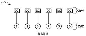
休止装置のコントローラとシリンダーを1対1で対応させる戦略では、エンジンのバルブカバーの下にうまくパッケージされないことがある大量の高価な制御コンポーネント(例えば、ソレノイド)と配線が必要になる。例えば、図2は、6つのシリンダー202を含む直列エンジンを非常に概略的に示している。1対1の戦略に沿って、この場合、各シリンダー202は、所与のシリンダーの吸気および排気休止装置に動作可能に接続された休止装置コントローラ204が関連付けられ、それにより、合計6つの休止装置コントローラが結果としてもたらされる。
The strategy of one-to-one correspondence of deactivator controllers to cylinders requires a large amount of expensive control components (eg, solenoids) and wiring that may not be well packaged under the engine valve cover. For example, FIG. 2 very schematically shows an in-line engine including six
さらに複雑なことに、大型ディーゼルエンジンで使用されるエンジン制動システムでは、エンジンブレーキバルブの運動を起動するために、追加の制御コンポーネント(ソレノイドなど)が必要になることがよくある。例えば、いわゆる「1.5ストローク」タイプのエンジン制動は、エンジン制動バルブ作動の適用と組み合わせて、排気主イベントバルブの作動の排除を必要とする。このような1.5ストロークエンジン制動を実装するための従来技術のシステムは、特許文献2に開示されており、これは、(吸気運動とは無関係に)排気運動の圧潰のためにソレノイドおよび制動運動を起動するために追加のソレノイドを利用する。その結果、特許文献2で説明されているタイプのシステムに1.5ストロークエンジン制動を備えた6シリンダーエンジンにシリンダー休止を追加するには、主イベントの休止用に12個の休止装置コントローラと、エンジンブレーキ制御用に少なくとも1つの追加コントローラ(ソレノイド)が必要になる。さらに、高速応答時間と低電力需要に対して部分的なブレーキ動力レベルを提供する能力を提供するためには、2つのコントローラがエンジンブレーキ制御に好ましいことが多い(例えば、6シリンダーエンジンでは、シリンダー1~3に対応する1つのエンジンブレーキコントローラ、およびシリンダー4~6に対応する別のエンジンブレーキコントローラ)。これは、第1のシリンダーグループ302(第1~第3のシリンダーを含む)および第2のシリンダーグループ304(第4~第6のシリンダーを含む)を含む同様の直列6エンジン300を示す図3に示されている。さらに示されるように、各シリンダーグループ302、304は、エンジン制動コントローラ306、308に関連付けられており、その結果、合計14個のコントローラが、1.5ストロークのエンジン制動およびシリンダー休止を提供している。これはコストがかかるだけでなく、エンジンバルブカバーの下のスペースに厳しい制約があるため、エンジンにパッケージすることはしばしば不可能である。
To further complicate matters, engine braking systems used in large diesel engines often require additional control components (such as solenoids) to initiate motion of the engine brake valves. For example, so-called "1.5-stroke" type engine braking requires elimination of exhaust main event valve actuation in combination with application of engine braking valve actuation. A prior art system for implementing such 1.5-stroke engine braking is disclosed in U.S. Pat. Utilizes additional solenoids to initiate movement. Consequently, to add cylinder deactivation to a 6-cylinder engine with 1.5-stroke engine braking in a system of the type described in US Pat. At least one additional controller (solenoid) is required for engine braking control. Additionally, two controllers are often preferred for engine braking control to provide fast response time and the ability to provide partial braking power levels for low power demands (e.g., in a six-cylinder engine, cylinder One engine brake controller for cylinders 1-3 and another engine brake controller for cylinders 4-6). This shows a similar inline 6
したがって、上記の欠点を克服するシリンダー休止技術は、当技術分野への歓迎すべき追加となるであろう。 Therefore, a cylinder deactivation technique that overcomes the above drawbacks would be a welcome addition to the art.
一実施形態では、本開示は、複数のシリンダーを含む内燃エンジンを説明し、複数のシリンダーのそれぞれは、少なくとも1つの吸気バルブおよび少なくとも1つの排気バルブを含む。複数の吸気休止装置は、複数のシリンダーに関連付けられ、複数のシリンダーの各シリンダーについて、複数の吸気休止装置のうちの少なくとも1つの吸気休止装置が、少なくとも1つの吸気バルブに動作可能に接続され、少なくとも1つの吸気バルブの作動が許可される吸気起動状態、または少なくとも1つの吸気バルブの作動が許可されない吸気休止状態のいずれかで動作するように制御可能である。内燃エンジンは、複数のシリンダーに関連する複数の排気休止装置をさらに含み、複数のシリンダーの各シリンダーについて、複数の排気休止装置のうちの少なくとも1つの排気休止装置が、少なくとも1つの排気バルブに動作可能に接続され、少なくとも1つの排気バルブの作動が許可される排気起動状態、または少なくとも1つの排気バルブの作動が許可されない排気休止状態のいずれかで動作するように制御可能である。吸気休止装置コントローラは、複数のシリンダーのうちの少なくとも2つのシリンダーに関連する吸気休止装置に動作可能に接続され、排気休止装置コントローラは、少なくとも2つのシリンダーに関連する排気休止装置に動作可能に接続される。 In one embodiment, the present disclosure describes an internal combustion engine that includes multiple cylinders, each of which includes at least one intake valve and at least one exhaust valve. a plurality of intake deactivation devices associated with the plurality of cylinders, at least one intake deactivation device of the plurality of intake deactivation devices being operatively connected to at least one intake valve for each cylinder of the plurality of cylinders; It is controllable to operate either in an intake activated state in which operation of at least one intake valve is permitted, or in an intake rest state in which operation of at least one intake valve is not permitted. The internal combustion engine further includes a plurality of exhaust deactivators associated with the plurality of cylinders, wherein for each cylinder of the plurality of cylinders, at least one exhaust deactivator of the plurality of exhaust deactivators operates at least one exhaust valve. operably connected and controllable to operate in either an exhaust active state in which operation of the at least one exhaust valve is permitted, or an exhaust inactive state in which operation of the at least one exhaust valve is not permitted. An intake deactivator controller is operably connected to intake deactivators associated with at least two of the plurality of cylinders, and an exhaust deactivator controller is operably connected to exhaust deactivators associated with at least two cylinders. be done.
複数の吸気休止装置および排気休止装置のそれぞれは、油圧制御休止装置を含み得、その場合、休止装置コントローラおよび排気休止装置コントローラは、それぞれ、油圧流体を制御するソレノイドを含み得る。 Each of the plurality of intake deactivators and exhaust deactivators may include a hydraulically controlled deactivator, in which case the deactivator controller and the exhaust deactivator controller may each include a solenoid for controlling hydraulic fluid.
内燃エンジンは、少なくとも2つのシリンダーに関連する吸気休止装置を吸気休止状態にさせるように吸気休止装置コントローラを動作させ、少なくとも2つのシリンダーに関連する排気休止装置を排気休止状態にさせるように排気休止装置コントローラを動作させるように構成されたエンジンコントローラを含んでもよい。エンジンコントローラによる吸気休止装置コントローラおよび排気休止用コントローラの動作は、実質的に同時に起こり得る。あるいは、エンジンコントローラは、吸気休止装置コントローラを動作させて、吸気休止装置を吸気休止状態にし、その後、排気休止装置コントローラを動作させて、排気休止装置を排気休止状態にする、またはその逆を行うことができる。吸気または排気の休止装置をそれぞれの休止状態にするときのそのようなその後の動作は、期間の完了もしくはクランクシャフトの角度範囲、またはその両方に基づくことができる。期間もしくはクランクシャフトの角度範囲のいずれか、またはその両方は、エンジン速度、油温、冷却剤温度、または油圧のうちの少なくとも1つに基づくことができる。エンジンコントローラはまた、排気休止装置コントローラを動作させて排気休止装置を排気起動状態にし、続いて吸気休止装置コントローラを動作させて、吸気休止装置が吸気休止状態での動作を停止するように制御し、またはその逆を行うように構成することができる。吸気または排気の休止装置をそれぞれの起動状態にするときのそのようなその後の動作は、クランクシャフトの角度範囲に基づくことができる。 The internal combustion engine operates an intake deactivator controller to cause intake deactivation devices associated with at least two cylinders to enter an exhaust deactivation state and exhaust deactivation devices associated with at least two cylinders to enter an exhaust deactivation state. An engine controller configured to operate the device controller may be included. Operation of the intake deactivator controller and the exhaust deactivation controller by the engine controller may occur substantially simultaneously. Alternatively, the engine controller operates the intake deactivation device controller to place the intake deactivation device in the intake deactivation state and then operates the exhaust deactivation device controller to place the exhaust deactivation device in the exhaust deactivation state, or vice versa. be able to. Such subsequent operation when deactivating the intake or exhaust deactivators, respectively, may be based on the completion of the period or the angular extent of the crankshaft, or both. Either the duration or the crankshaft angle range, or both, can be based on at least one of engine speed, oil temperature, coolant temperature, or oil pressure. The engine controller also operates the exhaust gas deactivation device controller to place the exhaust gas deactivation device in the exhaust activation state, and then operates the intake deactivation device controller to control the intake deactivation device to stop operating in the intake deactivation state. , or vice versa. Such subsequent operation when activating the intake or exhaust deactivator can be based on the angular range of the crankshaft.
特定の実施形態では、直列エンジンは6つのシリンダーを有し、正の動力動作中、複数のシリンダーは、第1のシリンダー、次に第5のシリンダー、次に第3のシリンダー、次に第6のシリンダー、次いで第2のシリンダー、次に第4のシリンダーの順に繰り返し点火される。この実施形態では、吸気休止装置コントローラは、第1~第3のシリンダーを含む第1のシリンダーグループ、または第4~第6のシリンダーを含む第2のシリンダーグループについて吸気休止装置に動作可能に接続され、排気休止装置コントローラは、第1シリンダーグループまたは第2シリンダーグループについて排気休止装置に動作可能に接続される。この実施形態のエンジンコントローラは、第1のシリンダーグループまたは第2のシリンダーグループ内の選択されたシリンダーの主排気イベントが失われないように排気休止装置コントローラを動作させ、第1のシリンダーグループまたは第2のシリンダーグループの排気休止装置を排気休止状態にさせるように構成される。さらに、この実施形態のエンジンコントローラは、第1のシリンダーグループまたは第2のシリンダーグループ内の選択されたシリンダーの主吸気イベントが失われないように吸気休止装置コントローラを動作させ、第1のシリンダーグループまたは第2のシリンダーグループの吸気休止装置を吸気休止状態にさせるように構成される。
In a particular embodiment, the in-line engine has six cylinders, and during positive power operation the multiple cylinders are the first cylinder, then the fifth cylinder, then the third cylinder, then the sixth cylinder.
別の実施形態では、本開示は、複数のシリンダーを含む内燃エンジンを説明し、複数のシリンダーのそれぞれは、少なくとも1つの吸気バルブおよび少なくとも1つの排気バルブを含む。複数の吸気休止装置は、複数のシリンダーに関連付けられ、複数のシリンダーの各シリンダーについて、複数の吸気休止装置のうちの少なくとも1つの吸気休止装置は、少なくとも1つの吸気バルブに動作可能に接続され、少なくとも1つの吸気バルブの作動が許可される吸気起動状態、または少なくとも1つの吸気バルブの作動が許可されない吸気休止状態のいずれかで動作するように制御可能である。内燃エンジンは、複数のシリンダーに関連する複数の排気休止装置をさらに含み、複数のシリンダーの各シリンダーについて、複数の排気休止装置のうちの少なくとも1つの排気休止装置が、少なくとも1つの排気バルブに動作可能に接続され、少なくとも1つの排気バルブの作動が許可される排気起動状態、または少なくとも1つの排気バルブの作動が許可されない排気休止状態のいずれかで動作するように制御可能である。休止装置コントローラは、複数のシリンダーのうちの少なくとも2つのシリンダーに関連する吸気休止装置および排気休止装置に動作可能に接続されている。さらに、エンジンコントローラが提供され、クランクシャフトの角度範囲に基づいて休止装置コントローラを動作させて、少なくとも2つの吸気休止装置を吸気休止状態に、少なくとも2つの排気休止装置を排気休止状態にさせるように構成される。エンジンコントローラはまた、少なくとも2つのシリンダーのうちの選択されたシリンダーの主排気イベントが失われず、選択されたシリンダーの主吸気イベントが失われるように、休止装置コントローラを動作させるように構成され得る。さらに、エンジンコントローラは、休止装置コントローラを動作させて、少なくとも2つのシリンダーに関連する吸気休止装置を吸気起動状態にし、少なくとも2つのシリンダーに関連する少なくとも2つの排気休止装置を排気起動状態にするように、かつそれにより選択されていないシリンダー(すなわち、選択されたシリンダー以外の少なくとも2つのシリンダーのそれらのシリンダー)の主排気イベントが、選択されていないシリンダーの吸気イベントの前に発生するように、構成されてもよい。 In another embodiment, the present disclosure describes an internal combustion engine including multiple cylinders, each of the multiple cylinders including at least one intake valve and at least one exhaust valve. a plurality of intake deactivation devices associated with the plurality of cylinders, wherein for each cylinder of the plurality of cylinders, at least one intake deactivation device of the plurality of intake deactivation devices is operatively connected to at least one intake valve; It is controllable to operate either in an intake activated state in which operation of at least one intake valve is permitted, or in an intake rest state in which operation of at least one intake valve is not permitted. The internal combustion engine further includes a plurality of exhaust deactivators associated with the plurality of cylinders, wherein for each cylinder of the plurality of cylinders, at least one exhaust deactivator of the plurality of exhaust deactivators operates at least one exhaust valve. operably connected and controllable to operate in either an exhaust active state in which operation of the at least one exhaust valve is permitted, or an exhaust inactive state in which operation of the at least one exhaust valve is not permitted. A deactivator controller is operatively connected to intake deactivators and exhaust deactivators associated with at least two of the plurality of cylinders. Further, an engine controller is provided to operate the deactivator controller based on the angular range of the crankshaft to cause the at least two intake deactivators to be in intake deactivation and the at least two exhaust deactivators to be in exhaust deactivation. Configured. The engine controller may also be configured to operate the hibernation device controller such that a selected one of the at least two cylinders is not lost a primary exhaust event and a selected cylinder is not lost a primary intake event. Further, the engine controller operates the deactivator controller to place intake deactivators associated with the at least two cylinders in an intake active state and to place at least two exhaust deactivators associated with the at least two cylinders in an exhaust active state. and whereby the main exhaust events of the non-selected cylinders (i.e. those cylinders of at least two cylinders other than the selected cylinder) occur before the intake events of the non-selected cylinders, may be configured.
対応する方法も本明細書に記載されている。 Corresponding methods are also described herein.
前述および他の特徴および利点は、添付の図面に関連して、特定の実施形態の以下の非限定的な説明において詳細に論じられる。 The foregoing and other features and advantages are discussed in detail in the following non-limiting description of certain embodiments in conjunction with the accompanying drawings.
本開示に従う特定のシステムおよび方法を説明する前に、本明細書で使用される様々な「ウィンドウ」の概念の図を通じて、より深い理解が提供され得る。本明細書に記載の休止装置および休止装置コントローラが、それらが以下に説明する機能を実行するという条件で様々な方法で実装され得ることが理解されるが、本開示の残りの部分は、休止装置および休止装置コントローラが、上述のように、油圧制御された休止装置およびソレノイドとして実装されると仮定する Before describing certain systems and methods according to the present disclosure, a better understanding may be provided through illustrations of various "window" concepts used herein. While it is understood that the hibernation device and hibernation device controller described herein may be implemented in a variety of ways, provided that they perform the functions described below, the remainder of this disclosure Assume that the device and resting device controllers are implemented as hydraulically controlled resting devices and solenoids as described above.
それを念頭に置いて、本明細書で使用されるように、ロック解除/圧潰ウィンドウまたはロック/非圧潰ウィンドウは、所与の休止装置の実際のロック解除/圧潰状態またはロック/非圧潰状態をそれぞれ達成することが望まれる特定のクランクシャフトの角度範囲を表す。当技術分野で知られているように、バルブ作動運動および他のタイミング関連のエンジン動作機能は、エンジン動作速度(例えば、毎分回転数(RPM))に依存しないクランクシャフト角度に関して説明することができる。典型的には、完全なエンジンサイクル(排気、吸気、圧縮および膨張段階を含む)は、クランクシャフトの2つの完全な回転(すなわち、720度)に関して説明され、この規則は、一般に、本開示において採用される。さらに、本明細書で使用される場合、クランクシャフト(またはその変形)の角度範囲は、動作が許可され、達成されることが求められるクランクシャフト角度の範囲を含むだけでなく、動作が抑制され、回避される必要があるクランクシャフト角度の範囲も含み得ることが理解される。 With that in mind, as used herein, an unlocked/collapsed window or locked/uncollapsed window represents the actual unlocked/collapsed or locked/uncollapsed state of a given resting device. Each represents a specific crankshaft angle range that it is desired to achieve. As is known in the art, valve actuation motion and other timing-related engine operating features can be described in terms of crankshaft angle independent of engine operating speed (e.g., revolutions per minute (RPM)). can. Typically, a complete engine cycle (including exhaust, intake, compression and expansion stages) is described in terms of two complete revolutions of the crankshaft (i.e. 720 degrees), and this convention is generally used in this disclosure Adopted. Further, as used herein, the angular range of a crankshaft (or variations thereof) includes not only the range of crankshaft angles over which motion is permitted and sought to be achieved, but also in which motion is inhibited. , may also include a range of crankshaft angles that need to be avoided.
このようなロック解除/圧潰またはロック/非圧潰ウィンドウは、休止装置コントローラの動作モードを切り替えるために必要な応答時間を考慮する、休止装置コントローラの通電ウィンドウとは区別されるべきである。例えば、ソレノイドベースの休止装置コントローラの場合、ソレノイド通電ウィンドウまたはソレノイド非通電ウィンドウはそれぞれ、所与の休止装置で十分な油圧流体圧力を生成して、所望のロック解除/圧潰を開始するためのソレノイドおよび関連する油圧システムの応答時間、または休止装置を減圧して所望のロック/非圧潰を実行するための応答時間を指している。換言すれば、ソレノイドの通電/非通電ウィンドウは、所望のロック解除/圧潰またはロック/非圧潰ウィンドウを達成するためにどのくらいの時間を考慮しなければならないかを表す。さらに、本開示は、クランクシャフトの角度範囲に加えて、または代わりとして、好ましくはないが使用され得る、休止装置コントローラ/休止装置の動作を順序付けるために使用され得る期間に言及する。 Such unlock/collapse or lock/uncollapse windows are to be distinguished from dormant device controller power-on windows, which take into account the response time required to switch the dormant device controller's operating mode. For example, in the case of a solenoid-based deactivator controller, the solenoid energized or non-solenoid energized windows, respectively, generate sufficient hydraulic fluid pressure at a given deactivator to activate the solenoid to initiate the desired unlock/collapse. and the response time of the associated hydraulic system, or the response time to depressurize the resting device to perform the desired lock/uncollapse. In other words, the energization/de-energization window of the solenoid represents how much time must be considered to achieve the desired unlock/collapse or lock/uncollapse window. Additionally, this disclosure refers to time periods that may be used to sequence the operation of the rest device controller/rest device that may be used in addition to, or instead of, crankshaft angular ranges, although this may not be preferred.
図4~図8は、これらの概念の様々な例を示している。例えば、図4は、後続の主排気イベントの休止の前に主排気イベント404の発生を許可し、このサイクルに関して主吸気イベント406の発生を許可しない、吸気および排気休止装置の両方に対する所望の圧潰ウィンドウ402を示す。本開示の残りの部分を通して、バルブイベントの開始後に始まる圧潰ウィンドウは、そのバルブイベントの喪失をもたらさないと仮定され、他方、バルブイベントの開始後に始まる非圧潰ウィンドウは、バルブイベントが実際にエンジンバルブに伝達されるように、非圧潰/再ロックをもたらさないと仮定される。(特許文献1に記載されているロック機構の文脈では、これは、ロック機構に課せられた主イベントのロードにより、ロック機構が再びアンロードされるときまで、ロック状態からロック解除状態への切り替えが妨げられるためであり、反対のシナリオでは、ロック機構が再びアンロード状態になるまで、同様に再ロックは発生し得ない。)したがって、圧潰ウィンドウ402は、主排気イベント404の開始直後に始まるので、主排気イベント404は、休止を通じて失われない。しかしながら、ウィンドウ402は、主吸気イベント406の開始前に発生および終了するので、主吸気イベントは、このエンジンサイクルおよび後続のエンジンサイクルの間圧潰し(すなわち、失われ)、このとき、主排気イベント404も圧潰する。その結果、この圧潰ウィンドウは、すべてのバルブ運動を無効にする前にシリンダーから残留ガスを効果的に空にする、つまり、休止されたシリンダーは真空を捕捉することになる。当技術分野で知られているように、このようにしてシリンダー内に真空を捕捉することは、(上死点(TDC)での)ピーク圧縮中にシリンダー内の摩擦を減少させる。多くのディーゼルエンジンには、真空で機能するように設計されていないピストンリングがあり、そのような真空が存在すると、シリンダー内に過剰な潤滑油が漏れる可能性があり、シリンダー内でその油が燃焼して、排出物や油消費の問題が発生する可能性がある。一方、多くのタイプのガソリンエンジンは、このような油消費の問題はなく、代わりに、シリンダーの摩擦を減少する真空の存在から恩恵を受けている。
4-8 illustrate various examples of these concepts. For example, FIG. 4 illustrates the desired collapse for both the intake and exhaust deactivators, allowing the
図4とは対照的に、図5は、後続の主吸気イベントの休止の前に主吸気イベント406の発生を可能にし、また、次のエンジンサイクルから始まる後続の主排気イベント404の喪失を結果としてもたらす、吸気および排気休止装置の両方に対する所望の圧潰ウィンドウ502を示す。主吸気イベント406がシリンダーへのガスの侵入を可能にし、主排気イベント404が次のエンジンサイクルで圧潰するため、シリンダー内のガスは排出されない、すなわち、ガスはシリンダー内にトラップされる。この場合、TDCでのピークシリンダー圧力は、真空がトラップされたシリンダーと比較してはるかに高くなる。このアプローチは、より高いシリンダー圧力からの追加のシリンダー摩擦をもたらすが、上記の油消費の問題は回避される。
In contrast to FIG. 4, FIG. 5 allows the occurrence of the
エンジンバルブの休止状態から起動状態への遷移の順序付けも検討に値する。吸気バルブの作動運動が、排気バルブの作動運動のそのような遷移の前に起動状態に遷移した場合、吸気バルブは、TDCの近くで開かれる。これが比較的高いシリンダー圧力に対して発生すると(以前に休止されたシリンダートラップガスの場合のように)、ノイズが発生する可能性があり、吸気バルブトレインコンポーネントに望ましくない高いロードが発生する可能性がある。 The sequencing of engine valve rest-to-start transitions is also worthy of consideration. If the intake valve actuation motion transitions to an active state prior to such transition of the exhaust valve actuation motion, the intake valve is opened near TDC. When this occurs for relatively high cylinder pressures (as was the case with previously deactivated cylinder trapped gas), it can create noise and undesirably high loads on intake valve train components. There is
図6は、トラップされたシリンダーガスから結果として生ずる高いシリンダー圧力に対して吸気バルブが開かないことを確実にするために、主吸気バルブ作動の前に主排気バルブ作動を再び起動させる、非圧潰ウィンドウ602を示し、これは、望ましくないノイズおよび/または過剰な吸気バルブトレインのロードの発生を防ぐための好ましい戦略である。ウィンドウ602は、主吸気イベント406の開始直後に始まるので、主吸気イベント406は発生しないが、後続の主排気イベント404は発生し、それにより、吸気休止装置がその後ロックするときに、より高いシリンダー圧力の発生を防止し、それにより、主吸気イベントが通常の圧力に対して開くことが許可される。
FIG. 6 shows a non-collapsed, reactivated main exhaust valve actuation before the main intake valve actuation to ensure that the intake valve does not open against the high cylinder pressure resulting from trapped cylinder gases. A
図7は、主排気イベント404が開始された後に始まる非圧潰ウィンドウ702を示しており、その結果、排気を再ロックすることは不可能である、すなわち、主排気イベント404は、このエンジンサイクルの間に失われる。しかしながら、ウィンドウ702は、主吸気イベント406が始まる前に終了するので、吸気バルブトレインは、前の主排気イベント404がなくても再ロックすることができ、したがって、吸気バルブは、TDCの近くで開く。上記のように、シリンダーにガスがトラップされている場合、これは好ましい戦略ではない。しかしながら、シリンダーにトラップされたガスがない場合、これは、以下でさらに説明するように、好ましい許容可能な動作条件となり得る。
FIG. 7 shows a
シリンダー毎にソレノイドを有するシステム(例えば、図2および図3)の場合、ソレノイドの通電および非通電ウィンドウは、それぞれ、圧潰および非圧潰ウィンドウが所望のクランクシャフト角度範囲内で発生するようにタイミングを合わせることができる。エンジン始動時などの冷油運転の場合、トラップされたガス戦略を達成するために約540度の持続時間を有するウィンドウ502においてソレノイドが応答しなければならないため(図5を参照)、これらのウィンドウを達成することはより困難な場合がある。ソレノイドの応答時間が540度のウィンドウよりも遅い場合は、起動/休止に時間をかけるために、油圧応答時間を考慮してソレノイドに通電および非通電する必要があり得る。 For systems with a solenoid per cylinder (e.g., FIGS. 2 and 3), the energized and de-energized windows of the solenoids are timed such that the collapse and de-collapse windows, respectively, occur within the desired crankshaft angle range. can be matched. These windows are can be more difficult to achieve. If the response time of the solenoid is slower than the 540 degree window, it may be necessary to energize and de-energize the solenoid to allow time for activation/deactivation to allow for hydraulic response time.
この例は図8に示され、油圧遅延を考慮するためにソレノイド通電ウィンドウ802が追加された圧潰ウィンドウ502を示している。図示される例では、休止ウィンドウ502は、通電ウィンドウ802の開始時に必要なソレノイドが通電される(それにより油圧流体の流れを可能にする)場合に満たされるであろう。この場合も、通電ウィンドウ802の長さは、油圧流体の流れを開くためのソレノイド応答時間に起因する予想される遅延、ならびにソレノイドおよび必要な油圧通路を流れる油圧流体の粘度に基づく。当業者によって理解されるように、ソレノイドおよび油圧遅延がクランク角度領域で変化するため、ソレノイド通電ウィンドウ802の持続時間はエンジン速度に依存する。例えば、より高いエンジン速度は、所与のソレノイドおよび/または油圧遅延に対して比較的大きな角度ウィンドウをカバーし、休止ウィンドウ502を開始するためのより長い時間を補償するために、通電イベントを早める(より早く発生させる)必要がある。さらに、より高いエンジン速度はまた、典型的にはより高い油圧およびより低い油粘度を有し、これは、ソレノイド通電ウィンドウ802の開始を遅らせる(後で発生させる)ことによって結果として生じるより速い圧力上昇時間を補償するために考慮に入れられる必要がある。
An example of this is shown in FIG. 8, which shows a
図9は、本開示による内燃エンジン900の一部の実施形態を概略的に示している。好ましくは、以下の図9~図16に関連して本明細書に記載される様々な実施形態は、直列6シリンダー内燃エンジンに適用可能である。しかしながら、これらの技術は、異なる数のシリンダー(例えば、4つのシリンダー、8つのシリンダーなど)およびシリンダーの向き(例えば、水平対向、Vなど)を有する内燃エンジンに等しく適用され得ることが理解される。
FIG. 9 schematically illustrates some embodiments of an
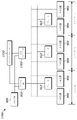
図9では、エンジン900は、複数のシリンダーを備える(3つのシリンダーのみが示され、シリンダー1、2、および3とラベル付けされている)。図9には3つのシリンダーが示されているが、図9に示される構成は、以下さらに詳細に説明するように、各吸気および排気休止装置が少なくとも2つのシリンダーに関連付けられていることを条件として、より多くのシリンダーに等しく適用されるか、または同様のシリンダーのグループ化に複製することができることが理解される。各シリンダーには、少なくとも1つの吸気休止装置902および少なくとも1つの排気休止装置904が関連付けられている。さらに、エンジン900は、少なくとも2つのシリンダーに対応する複数の吸気休止装置902に動作可能に接続された吸気休止装置コントローラ906と、同様に少なくとも2つのシリンダーに対応する複数の排気休止装置904に動作可能に接続された排気休止装置コントローラ908とを含む。しかしながら、図示する実施形態では、吸気休止装置906および排気休止装置908は、3つの図示されるシリンダーすべてについて、吸気休止装置902および排気休止装置904の動作を制御するように構成され、吸気休止装置コントローラ906と吸気休止装置902との間の油圧接続が実線で示され、排気休止装置コントローラ908と排気休止装置904との間の油圧接続は破線で示されている。各休止装置コントローラ906、908は、前述のように、油圧流体供給920(当技術分野で知られているオイルポンプ、1つ以上のアキュムレータなど)ならびにエンジンコントローラ930に動作可能に接続されている。当技術分野で知られているように、および休止装置コントローラを実装する油圧ソレノイドの場合、エンジンコントローラ930は、休止装置コントローラ906、908を通電/非通電させて、対応する休止装置902、904への油圧流体の流れを制御する電気信号を提供してもよい。
In FIG. 9,
個々の休止装置コントローラ906、908は、従来技術のシステムのような休止装置コントローラとシリンダーとの間の1対1の対応とは対照的に、2つ以上のシリンダーに関連付けられているため、エンジンのシリンダー休止動作を効果的に制御するために必要な休止装置コントローラ906、908の数は、大幅に減少し得る。例えば、図9が、3つのシリンダーの第1のグループ化の休止動作を制御する1つの吸気休止装置コントローラ906および1つの排気休止装置コントローラ908を示す範囲で、この構成は、6シリンダーエンジンにおける3つのシリンダーの第2のグループ化のために複製され得、図9のエンジン900は、図2および図3に示される従来技術によって必要とされる12個の休止装置コントローラとは対照的に、4つの休止装置コントローラのみを必要とするであろう。シリンダーのグループに対応する多数の休止装置コントローラの提供が現在好まれているが(油圧応答時間の短縮とシリンダーのよりきめ細かい制御のため)、6つのシリンダーエンジンの6つのシリンダーすべてに対して単一の吸気休止装置コントローラと単一の排気休止装置コントローラのみを有することで、休止装置コントローラの総数をさらに2つだけに減らすことができる。
Because individual
さらに、図9に示されるように、複数のオプションのエンジン制動アセンブリ912に動作可能に接続されるエンジン制動コントローラ910がオプションで提供されてもよい。エンジン制動コントローラ910とエンジン制動アセンブリとの間の油圧接続は、点線で示されている。この場合、エンジン制動アセンブリ912のそれぞれは、圧縮解放制動(特に1.5ストローク圧縮解放制動)、ブリーダー制動などの、各シリンダーに対してエンジン制動動作を選択的に提供する当技術分野で知られているタイプのものでもよい。あるいは、アセンブリ912のそれぞれは、当技術分野で知られている他のタイプの補助バルブ作動運動を提供するように構成されてもよい。この場合も、多くのエンジン制動アセンブリが油圧制御され得る範囲で、エンジン制動コントローラ910は、吸気/排気休止装置コントローラ906、908と構造が同一の油圧ソレノイドを備えてもよい。エンジン制動コントローラ910およびエンジン制動アセンブリ912は必要とされないが、本明細書に記載の様々な実施形態は、エンジン900内にパッケージ化される必要がある休止装置/コントローラの数を、適宜、減らすことができる範囲で、そのようなコンポーネントを含むシステムに特に適用可能である。
Additionally, as shown in FIG. 9, an
以下でさらに詳細に説明するように、休止装置の圧潰/ロック解除を順序付ける能力は、別個の吸気および排気休止装置コントローラ906、908を制御する独自の戦略を通じて提供される。好ましくは、そのような戦略は、ウィンドウもしくはクランクシャフトの角度範囲、および/または、あまり好ましくはないが、吸気および排気休止装置コントローラ906、908の動作間の期間に基づく。休止状態から起動状態に戻る休止装置902、904の遷移は、時間ベースのソレノイド遅延(期間)もこの目的のために使用され得るが、好ましくはクランクシャフトの角度範囲に基づいて、同様の反対の方法で再び扱われてもよい。
As will be described in further detail below, the ability to sequence deactivator collapse/unlock is provided through a unique strategy of controlling separate intake and exhaust deactivator controllers 906,908. Preferably, such a strategy is based on the window or crankshaft angle range and/or, less preferably, the period between operation of the intake and exhaust deactivator controllers 906,908. The transition of the
図10は、図9の実施形態によるシリンダー休止動作を提供するための処理のフローチャートを示している。一実施形態では、図10に示される処理は、エンジンコントローラ930によって実施され、好ましくは、1つ以上のメモリデバイスに記憶された実行可能命令の形で実装され、実行可能命令はメモリデバイスに動作可能に接続された少なくとも1つの処理装置によって実行される。とにかく、ブロック1002から開始して、シリンダーを休止する必要があるかどうか、すなわち、休止装置902、904をそれぞれの休止状態にする必要があるかどうかの決定がなされる。そのような決定は、特定の条件のセットが現在存在するという決定に応答して(例えば、エンジンコントローラが現在の車速およびロードが燃料消費を削減する機会を提供すると決定する場合)、または明示的な要求に応答して(例えば、シリンダー休止によって排気後処理温度を望ましく上げることが可能である後処理熱管理の場合)なされてもよい。さらに、ステップ1002でシリンダーを休止する決定は、以前に正の動力発生状態(すなわち、起動状態)にあったシリンダーに条件付けられる必要はない。例えば、当技術分野では、コールドエンジン始動中にディーゼルエンジンでシリンダー休止を使用することが知られている。
FIG. 10 shows a flowchart of a process for providing cylinder deactivation operation according to the embodiment of FIG. In one embodiment, the processing illustrated in FIG. 10 is performed by
シリンダー休止が必要であると決定されると、処理はステップ1004および1006に続く。ステップ1004および1006は並行して示されているが、休止されたシリンダーの望ましい動作状態を達成するために、実際には、これらのステップは、以下に説明するように、実質的に同時に、またはステップ1006がステップ1004の後に発生するように、またはステップ1004がステップ1006の後に発生するように実施され得る。ステップ1004において、エンジンコントローラは、吸気休止装置コントローラ906を動作させて、少なくとも2つのシリンダーに関連する吸気休止装置902を吸気休止状態にする。上記の油圧制御された休止装置およびソレノイドの例の文脈において、これは、エンジンコントローラ930が適切な信号を送信して吸気休止装置ソレノイド906を通電させ、それにより、油圧流体が吸気休止装置902に流れるようにし、吸気休止装置902がロック解除/圧潰されるようにすることによって行われる。同様に、ステップ1006において、エンジンコントローラは、排気休止装置コントローラ908を動作させて、少なくとも2つのシリンダーに関連する排気休止装置904を排気休止状態にする。ここでも、上記の油圧制御された休止装置およびソレノイドの例の文脈では、これは、エンジンコントローラ930が適切な信号を送信して吸気休止装置ソレノイド908を通電させ、それにより、油圧流体が排気休止装置904に流れるようにし、排気休止装置904がロック解除/圧潰されるようにすることによって行われる。
If it is determined that cylinder deactivation is required, processing continues at
上記のように、ステップ1004および1006で説明される動作は、実質的に同時にまたは順番通りに発生することが許可され得る。現在の好ましい実施形態では、休止装置をそれらの休止状態にするそのような同時または規則正しい性能は、達成されるべき結果に応じて変化し得るクランクシャフトの角度範囲に基づく。例えば、図9の各シリンダー内に真空をトラップすることが望まれる場合、図4に示される圧潰ウィンドウ402が使用されてもよい。より具体的には、図4に示される例示的な圧潰ウィンドウ402は、約130度のクランク角度(ただし、いずれの場合も、主排気イベント404の開始後)から約320度のクランク角度(ただし、いずれの場合も、主吸気イベント406の開始前)まで延在する。それぞれの吸気および排気休止装置コントローラ906、908が、このウィンドウ402内の任意の場所でそれぞれの休止状態を開始するように制御されるとすると、結果として生じる休止状態は、排気バルブ作動運動の前に吸気バルブ作動運動が無効になるように順番が付けられ、それによってシリンダー内に所望の真空がトラップされる。他方、図9の各シリンダーにガスをトラップさせることが望まれる場合、図5の圧潰ウィンドウ502が使用されてもよい。より具体的には、図4に示される例示的な圧潰ウィンドウ502は、約340度のクランク角度(ただし、いずれの場合も、主吸気イベント406の開始後)から約120度のクランク角度(モジュロ720度、および、いずれの場合も、主排気イベント404の開始前)まで延在する。それぞれの吸気および排気休止装置コントローラ906、908が、このウィンドウ502内の任意の場所でそれぞれの休止状態を開始するように制御されるとすると、結果として生じる休止状態は、吸気バルブ作動運動の前に排気バルブ作動運動が無効になるように順番が付けられ、それによってシリンダー内に所望のガスがトラップされる。
As noted above, the operations described in
それぞれの吸気および排気の休止状態にされると、吸気および排気の休止装置902、904は、吸気および排気の休止装置コントローラ906、908がこのようにエンジンコントローラ930によって動作される限り、かつ、それらの動作の切り替えが発生するまで、このようにして続けられる。これは、ステップ1008に反映され、ここで、シリンダーを再起動するかどうか、すなわち、休止装置902、904をそれぞれの起動状態にするかどうかが決定される。この場合も、そのような決定は、特定の条件のセットが現在存在するという決定に応答して(例えば、加速状態など、追加のエンジン動力の要求が必要であるとエンジンコントローラが決定する場合、またはコールドエンジン始動手順が正常に完了したことの決定)または明示的な要求に応答してなされてもよい。
Upon respective intake and exhaust deactivation states, the intake and exhaust deactivators 902, 904 are activated as long as the intake and
シリンダーの再起動が必要であると決定されると、処理はステップ1010および1012に続く。ステップ1004および1006と同様に、ステップ1010および1012は並行して示されているが、シリンダーを起動するために、実際には、これらのステップは、以下に説明するように、実質的に同時に、またはステップ1012がステップ1010の後に発生して、またはステップ1010がステップ1012の後に発生して実施され得る。ステップ1010において、エンジンコントローラは、吸気休止装置コントローラ906を動作させて、少なくとも2つのシリンダーに関連する吸気休止装置902を吸気起動状態にさせる。上記の油圧制御された休止装置およびソレノイドの例の文脈において、これは、エンジンコントローラ930が適切な信号を送信して吸気休止装置ソレノイド906を非通電させることによって行われ、それにより、ロック/非圧潰されるよう油圧流体が吸気休止装置902に流れることを停止させる。同様に、ステップ1012において、エンジンコントローラは、排気休止装置コントローラ908を動作させて、少なくとも2つのシリンダーに関連する排気休止装置904を排気起動状態にさせる。ここでも、上記の油圧制御された休止装置およびソレノイドの例の文脈では、これは、エンジンコントローラ930が適切な信号を送信して吸気休止装置ソレノイド908を非通電させることによって行われ、それにより、ロック/非圧潰されるよう油圧流体が排気休止装置904に流れることを停止させる。
If it is determined that a cylinder restart is required, processing continues at
上記のように、ステップ1010および1012で説明される動作は、実質的に同時にまたは順番通りに発生することが許可され得る。休止装置902、904が特定の順番に従ってそれぞれの休止状態にされた範囲で、その順番は、休止装置902、904をそれぞれの起動状態にするときに逆にされることが好ましい。この逆の順番は、休止された状態に入るときにガスをトラップするように休止されたシリンダーが以前に動作された場合は特に望ましいが(非常に高いシリンダー圧力に対して吸気バルブを再び開けようとする可能性を回避するため)、これは、真空をトラップするように休止されたシリンダーが以前に動作された場合は必ずしも要件である必要がない(再び開けられる時に吸気バルブが高いシリンダー圧力に遭遇しないため)。にもかかわらず、ここでも、現在の好ましい実施形態では、休止装置をそれらの起動状態にするそのような同時または順番通りの実施は、達成されるべき結果に応じて変化し得るクランクシャフトの角度範囲に基づく。例えば、図9の休止されたシリンダーがガスをトラップするように動作された場合、図6に示される非圧潰ウィンドウ602が使用されてもよい。より具体的には、図6に示される例示的な非圧潰ウィンドウ602は、約340度のクランク角度(ただし、いずれの場合も、主吸気イベント406の開始後)から約120度のクランク角度(モジュロ720度のクランク角度、ただし、いずれの場合も、主排気イベント404の開始前)まで延在する。それぞれの吸気および排気休止装置コントローラ906、908が、このウィンドウ602内の任意の場所でそれぞれの起動状態を開始するように制御されるとすると、結果として生じる起動状態は、排気バルブ作動運動が吸気バルブ作動運動の前に再び有効になるように順番が付けられ、それによってより高いシリンダー圧力に対して吸気バルブが開かれることが回避される。他方、図9の休止されたシリンダーが真空をトラップするように動作された場合、図7の圧潰ウィンドウ702が使用されてもよい。より具体的には、図7に示される例示的な圧潰ウィンドウ702は、約130度のクランク角度(ただし、いずれの場合も、主排気イベント404の開始後)から約320度のクランク角度(ただし、いずれの場合も、主吸気イベント406の開始前)まで延在する。それぞれの吸気および排気休止装置コントローラ906、908が、このウィンドウ702内の任意の場所でそれぞれの休止状態を開始するように制御されるとすると、結果として生じる起動状態は、排気バルブ作動運動の前に吸気バルブ作動運動が再び有効になるように順番が付けられ、それによって比較的低いシリンダー圧力に対して吸気バルブが開くことが許可される。
As noted above, the operations described in
前述のように、休止装置902、904を休止または起動状態にさせる動作は、クランクシャフトの角度範囲に基づくものとして上述されたが、これらの決定は、代わりに期間に基づくこともできる。すなわち、例えば、休止装置コントローラ906、908のうちの1つを動作させて対応する休止装置をそれらの休止状態にさせた後、他の休止装置コントローラ906、908を動作させて対応する休止装置をそれらの休止状態にさせる前に、ある期間または遅延が使用されてもよい。しかしながら、そのような期間は、エンジンの動作速度(例えば、RPM)および休止装置902、904の応答時間を考慮に入れる必要がある。例えば、比較的低いエンジン速度では、休止装置902、904の応答時間は、単一のエンジンサイクルを完了するのにかかる時間内に所望の動作が行われ得るように十分に短くてもよく、その場合、遅延を実現するための期間の使用は実現可能であり得る。しかしながら、より高いエンジン速度では、単一のエンジンサイクルの持続時間は、休止装置902、904の応答時間と比較して短すぎ、したがって、多数のエンジンサイクルにまたがる時間遅延を必要とし得る。さらに、休止装置コントローラ906、908の応答時間に影響を及ぼし得る他のエンジン動作パラメータもまた、このように考慮され得る。例えば、油圧流体(エンジンオイル)の粘度は温度の影響を受けることが理解される。その結果、所望の順番付けを実行するための好適な期間の決定は、油温もしくは冷却剤温度、またはその両方などの様々な温度関連パラメータを考慮に入れることができる。さらに、油圧供給920によって提供する油圧は、時間とともに変化する場合があり、これは、休止装置コントローラ906、908の応答時間に明らかに影響を与えるであろう。したがって、所望の順番付けを実行するための好適な期間の決定は、その時点での利用可能な油圧を考慮に入れてもよい。要するに、好適な期間は、記載されたエンジンパラメータ値のいずれか1つ、またはそれらの任意の所望の組み合わせに基づいてもよい。
As noted above, although the actions to deactivate or activate the
さらに、これらのパラメータは、同様に、休止装置コントローラ906、908を通じて所望の動作を実行するための好適な角度範囲の決定に適用可能である。例えば、コントローラの応答時間が速くならずに、エンジン速度が上がると、休止装置コントローラの応答時間に対応するために、より広い範囲のクランクシャフト角度が必要になる場合がある。他方、図13が示すように、油圧および温度の上昇とともに、休止を実行するためのコントローラの応答時間は減少する。その結果、エンジン速度の上昇に伴って油圧および/または温度が上昇した場合、コントローラの応答時間の短縮を考慮に入れる必要がある。
Further, these parameters are similarly applicable through the
トラップされたガスに対する吸気および排気バルブの休止および起動状態の順序付け、ならびにそのようなトラップされたガスの放出に加えて、休止装置902、904の部分的な係合の問題も考慮されるべきである。上記のように、休止装置902、904は、典型的には、バルブトレインをロックおよびロック解除するために移動する機械的要素によって油圧作動される。そのような休止装置に適用される油圧流体の圧力上昇が、主イベントの開始時にロック機構が部分的にのみ移動するようにタイミングがとられる場合、圧潰する部材にかかる応力が増加するリスクがある。
In addition to sequencing the deactivation and activation states of intake and exhaust valves to trapped gases, and releasing such trapped gases, the issue of partial engagement of
典型的には、ロック機構がこの遷移状態にあるときにソレノイドへの通電が発生する時間ウィンドウがあり、それは回避される必要がある。図11は、対応する休止装置コントローラに通電すると、任意の関連する休止装置の部分的なロック/ロック解除状態を潜在的に引き起こす可能性がある、領域1104(約65~115度のクランク角度の長方形のウィンドウとして示される)を示している。後続の主バルブイベント1102のロードがそのような休止装置にかかると、休止装置の急速かつ突然の圧潰の可能性があり、これは不適切な動作またはエンジンの損傷にさえつながる可能性がある。休止装置コントローラが主イベントの近くで通電される場合(通電のタイミングが遅い)、休止装置での油圧流体の圧力は、休止装置をロック解除するのに十分に上昇しない場合があり、主イベントの停止につながらない。他方、休止装置コントローラがより早く通電される場合(早いタイミング)、対応する休止装置での油圧流体の圧力は、そのような休止装置を完全かつ確実にロック解除するのに十分高くなる。このように理解すると、領域1104は、休止装置を休止状態にしようとするときに使用されるべきではないクランクシャフトの角度範囲の一部であると理解され、すなわち、この領域内にある休止装置コントローラの動作は抑制されるべきである。
There is typically a window of time during which energization of the solenoid occurs when the locking mechanism is in this transitional state, which must be avoided. FIG. 11 illustrates region 1104 (about 65-115 degrees of crank angle) where energizing the corresponding resting device controller could potentially cause a partial lock/unlock condition of any associated resting device. shown as a rectangular window). When a subsequent
吸気イベントと排気イベントの休止を組み合わせる場合、(吸気バルブまたは排気バルブ)のいずれかの開放イベントでこの発生を防ぐために、部分的な係合を回避する必要がある対応する第2の領域がある。この例を図12に示し、部分的な係合が起こり得る2つの領域1202、1208が示される(第1の領域1202は、図示される主吸気イベント1206に適用可能であり、第2の領域1208は、図示される主排気イベント1204に適用可能である)。この場合も、これらの領域は、休止装置906、908の動作が回避されるべきクランクシャフトの角度範囲の一部を構成する。休止装置コントローラとシリンダーの間に1対1の対応が提供された場合(図2および図3のように)、適切な領域においてそれぞれの休止装置/ソレノイドのそれぞれを通電することによって部分的な係合および順序付けが制御され得る起動を達成することは比較的簡単である。ただし、同じ休止装置コントローラで多数のシリンダーを組み合わせる場合に課題が発生し、所望の休止の順番を満たすために必要なソレノイド通電が特定の禁止角度範囲内になり得るオーバーラップ条件を引き起こすように、適切な順序付けのために多数のクランクシャフト角度範囲を組み合わせてもよい。例えば、トラップされた真空での動作を可能にするために、ソレノイド通電の角度範囲は、一部の速度では、部分的な係合のリスクも存在し得る領域内になり得る。クランクシャフトの角度範囲がオーバーラップするというこの問題は、クランクシャフトの角度範囲(望ましい部分と禁止部分の両方を含む)がエンジン速度(または上記の他のエンジン動作パラメータ)の関数として変化することが理解される場合に特に深刻になり得る。
When combining intake and exhaust event pauses, there is a corresponding second region where partial engagement must be avoided to prevent this from occurring on either (intake or exhaust valve) opening event. . An example of this is shown in FIG. 12 where two
好ましくは、潜在的にオーバーラップするクランクシャフト角度領域の影響を軽減するために、動作パラメータの異なる組み合わせについてソレノイド応答時間(そして、その結果、特定の休止装置コントローラ動作が達成され得るかどうか)を決定するためにマッピングが提供されてもよい。例えば、制御戦略を簡素化するために、休止装置の圧潰を確実にするのに十分な油圧までの通電時間からのソレノイドの時間応答は、圧力上昇時間が油圧と温度に従って索引付けされた2次元テーブルにリストされているテーブルに入力され得る。そして、この例を図13に示し、油圧(y軸;バール単位で表示)と温度(x軸;°Cで表示)の様々な組み合わせが、様々な圧力上昇時間に対応している。予想されるように、より高い油圧と温度の組み合わせ(つまり、図示される表の右下)は、休止を達成するのに十分な圧力に到達するためのより速い上昇時間に対応する。実際、これは、比較的「暖かい」エンジン動作の期間中にのみ動作が許可される既知の休止システムの経験とも相関し、一方、応答時間が遅いため、コールドオイルの動作は回避される。それにもかかわらず、特にシリンダー休止をコールドスタート/エンジンウォームアップ戦略の一部として使用できるディーゼルエンジンでは、コールドオイルシリンダー休止動作を提供することが望ましい。ただし、非常に冷たいオイルでは、利用可能な油圧の上昇が非常に遅くなり得るため、上記の角度ベースの休止で必要とされるように、シリンダー休止には単一のエンジンサイクルよりも長い時間が必要になる場合がある。これらの相反する要件に対処するために、禁止された角度範囲(潜在的な部分的な係合を回避するための要件に対処するため)と許可された角度範囲(望ましい順序付け要件に対処するため)を別々に処理することで、より大きな機会の角度で休止を行うことができ、したがって、部分的な係合を回避し、比較的簡単に適切な順序付けを提供し、より要求の厳しい動作条件の範囲にわたって、より堅牢なシステムが実現される。例えば、トラップされた真空に耐えることができるディーゼルエンジンの場合、角度ベースのタイミング(図4に示す)の組み合わせを時間ベースの遅延と組み合わせて、単一のエンジンサイクルよりも長い休止要件の必要性に対応することができる。時間ベースの遅延の代わりに、エンジンサイクルカウンタ(例えば、エンジンクランクシャフトの2回転ごと)を、以下でこの目的のために使用することができる。 Preferably, the solenoid response times (and thus whether a particular resting device controller operation can be achieved) are measured for different combinations of operating parameters to mitigate the effects of potentially overlapping crankshaft angle regions. A mapping may be provided to determine. For example, to simplify the control strategy, the time response of the solenoid from energization time to sufficient oil pressure to ensure the collapse of the deactivator is two-dimensional with pressure rise time indexed according to oil pressure and temperature. The tables listed in Tables can be entered. An example of this is then shown in FIG. 13, where different combinations of oil pressure (y-axis; expressed in bar) and temperature (x-axis; expressed in degrees Celsius) correspond to different pressure rise times. As expected, higher oil pressure and temperature combinations (ie, bottom right of chart shown) correspond to faster rise times to reach sufficient pressure to achieve rest. In fact, this also correlates with the experience of known rest systems that are only allowed to operate during periods of relatively "warm" engine operation, while cold oil operation is avoided due to the slow response time. Nonetheless, it is desirable to provide cold oil cylinder deactivation behavior, especially in diesel engines where cylinder deactivation can be used as part of a cold start/engine warm-up strategy. However, with very cold oil, the rise in available oil pressure can be very slow, so cylinder deactivation takes longer than a single engine cycle, as required by angle-based deactivation above. may be required. To address these conflicting requirements, the forbidden angular range (to address the requirement to avoid potential partial engagement) and the allowed angular range (to address the desired ordering requirement) ) can be treated separately to allow pauses to occur at greater angles of opportunity, thus avoiding partial engagement, providing proper sequencing with relative ease, and for more demanding operating conditions. A more robust system is achieved over the range of For example, for a diesel engine that can withstand a trapped vacuum, the combination of angle-based timing (shown in Figure 4) combined with time-based delays may result in the need for resting requirements longer than a single engine cycle. can correspond to Instead of a time-based delay, an engine cycle counter (eg, every two revolutions of the engine crankshaft) can be used below for this purpose.
この例は図14に示され、図4によって提供される順序付けに従って、3つのシリンダー(1~3)のグループ化が休止されている。図14のx軸は、シリンダー1~3についてシリンダー休止を開始することが決定されたときのT0から始まる時間の進行を示している。図示されるように、いくらかの時間(または特定の数のエンジンサイクル)の経過1402は、吸気休止装置コントローラ906を動作させて1404、対応する吸気休止装置902を吸気休止状態にするよう、図4に示される角度範囲402が開始したと決定される時間まで発生する(このウィンドウは、部分的係合を回避するためのすべての必要な抑制範囲を考慮する)。実質的に同時に(すなわち、そのような変更を同時に実行するためのエンジンコントローラ930の許容範囲および限界内で)、燃料は、シリンダー1~3から遮断される1406。その後、エンジンコントローラ930は、圧潰ウィンドウ402の次の発生の角度要件が満たされ得るまで、(例えば、図13の表に従って、または再び、エンジンサイクルに基づいて決定されるように)ある期間の間待機1408し、その時点で、排気休止装置コントローラ908を動作させて1410、対応する排気休止装置904を排気休止状態にさせることができる。このようにして、図示された戦略は、部分的な係合シナリオを回避し、トラップされたガスに対して吸気バルブを開かないターンオン順序を提供し、休止中にシリンダー内に真空をトラップする
An example of this is shown in FIG. 14, where the grouping of three cylinders (1-3) is paused according to the ordering provided by FIG. The x-axis of FIG. 14 shows the progression of time starting at T 0 when it is decided to initiate cylinder deactivation for cylinders 1-3. As shown, the passage of some time (or a certain number of engine cycles) 1402 causes the
一方、図15は、図14の反対のシナリオを示しており、図6に示されている順序付けに従って、3つのシリンダーのグループ化が再起動される。前述のように、これは通常、休止の順序を逆にすることによって成し遂げられる。この場合、T0において、シリンダー1~3についてシリンダーの起動を開始することが決定され、その時点で、シリンダー1~3に対する燃料の遮断1502が確実にされる。図示されるように、いくらかの時間(またはエンジンサイクル)の経過1504は、排気休止装置コントローラ908を動作させて1506、対応する排気休止装置904を排気休止状態にするよう、図6に示される角度範囲602が開始したと決定される時間まで発生する(このウィンドウは、ここでも部分的な係合を回避するためのすべての必要な抑制範囲を考慮する)。その後、エンジンコントローラ930は、非圧潰ウィンドウ602の次の発生の角度要件が満たされ得るまで、(例えば、図13の表に従って、または再びエンジンサイクルに従って決定されるように)ある期間の間待機1508し、その時点で、吸気休止装置コントローラ906を動作させて1510、対応する吸気休止装置902を吸気休止状態にすることができる。このようにして、図示された戦略は、すべてのトラップされたガスに対する吸気バルブの潜在的な作動を防止し、吸気または排気の休止装置902、904のいずれかの部分的な係合を防止する。吸気および排気の両方の休止装置がそれらの起動状態に戻されると、別の期間1512(またはエンジンサイクル)が経過することが許され得、その時点で、燃料は再び起動されたシリンダーに再導入される1514。実質的に同時に(すなわち、そのような変更を同時に実行するためのエンジンコントローラ930の許容範囲および限界内で)、燃料は、シリンダー1~3から遮断される1406。
FIG. 15, on the other hand, shows the opposite scenario of FIG. 14, in which the grouping of three cylinders is reactivated according to the ordering shown in FIG. As mentioned above, this is usually accomplished by reversing the order of pauses. In this case, at T 0 , it is decided to initiate cylinder activation for cylinders 1-3, at which
上記のように、遅延を実行する期間は、エンジンサイクルカウントによって置き換えられてもよい。さらに別の代替例では、期間は、一方がすでに発生するまで他方が発生することが許可されない順番通りの角度設定(すなわち、圧潰/非圧潰ウィンドウ)によって置き換えられてもよい。例えば、角度ベースの圧潰ウィンドウを設定することができるが、排気圧潰ウィンドウは、そのような吸気圧潰ウィンドウが発生し、所望の吸気休止を引き起こすまで尊重されない。排気圧潰ウィンドウ角度は次のエンジンサイクルまで到達しないため、時間ベースの遅延と同じ効果が達成され得る。 As noted above, the period for executing the delay may be replaced by the engine cycle count. In yet another alternative, the time periods may be replaced by sequential angle settings (ie, collapse/uncollapse windows) where the other is not allowed to occur until the other has already occurred. For example, an angle-based collapse window can be set, but the exhaust collapse window is not respected until such an inspiratory collapse window occurs, causing the desired inspiratory pause. Since the exhaust collapse window angle is not reached until the next engine cycle, the same effect as a time-based delay can be achieved.
ディーゼルエンジンの一般的な構成は、(エンジン/車両の前方に最も近いシリンダーには最小の番号が割り当てられ、エンジン/車両の後方に最も近いシリンダーには最大の番号が割り当てられる、一般的に受け入れられる規則に従う)1-5-3-6-2-4のシリンダー点火順番を持つインラインの6シリンダーエンジンである。図3に関して上で説明したように、シリンダー1~3を含む第1のグループおよびシリンダー4~6を含む第2のグループの場合のように、シリンダーを一緒にグループ化することによってシリンダー休止に対処することがしばしば望ましい。図16は、それぞれ第4~第6のシリンダーについて、1-5-3-6-2-4の点火順番に従って配置されている排気バルブリフトプロファイル1604-E、1605-E、1606-Eおよび吸気バルブリフトプロファイル1604-I、1605-I、1606-Iの例を示している。圧潰ウィンドウ1608、1610も図16に示され、これらのウィンドウは、シリンダー内にトラップされたガスを達成するために、図9のシステムと合わせて使用されてもよい。図16は、第2のグループのシリンダーに適用可能であるが、当業者は、適切に位置決めされた圧潰ウィンドウを含む同様の描写が、第1のグループのシリンダーにも提供され得ることを理解するであろう。
A common configuration for diesel engines is generally accepted (the cylinder closest to the front of the engine/vehicle being assigned the lowest number and the cylinder closest to the rear of the engine/vehicle being assigned the highest number). 1-5-3-6-2-4 cylinder firing order (according to the rules set forth in Cylinder stalls are addressed by grouping the cylinders together, such as with the first group comprising cylinders 1-3 and the second group comprising cylinders 4-6, as described above with respect to FIG. It is often desirable to FIG. 16 shows exhaust valve lift profiles 1604-E, 1605-E, 1606-E and intake valve lift profiles 1604-E, 1605-E, 1606-E arranged according to the firing order of 1-5-3-6-2-4 for cylinders 4-6, respectively. Examples of valve lift profiles 1604-I, 1605-I, 1606-I are shown.
図16に示されるスキームは、第1のエンジンサイクル中に3つのシリンダーすべてについて吸気イベントの発生を許可し、次に、次のエンジンサイクル(および休止状態の期間中の後続のサイクル)について排気および吸気イベントの発生を防止して、シリンダー内にガスをトラップするように設計されている。具体的には、エンジンコントローラ930は、排気休止用コントローラ908を動作(通電)させて、排気圧潰ウィンドウ1608を、シリンダー4の主排気イベント1604-Eの開始直後に開始させ、シリンダー5の主排気イベント1605-Eの開始直前に終了させる。これにより、シリンダー4の主排気イベント1604-Eが発生し、シリンダー5および6の後続のすべての主排気イベント1605-E、1606-Eが、関連する休止装置904がそれぞれの休止状態にされるために失われることが可能になる。この時点で、シリンダー5とシリンダー6の両方には、これらのシリンダーの以前に発生した主吸気バルブイベント1605-I、1606-Iにより、その中にすでにガスがあり、これらのシリンダーの休止装置が圧潰すると、そのようなガスが中にトラップされたままとなることが確実になる。さらに、同じエンジンサイクルにおいて、エンジンコントローラ930は、吸気休止用コントローラ906を動作(通電)させて、吸気圧潰ウィンドウ1610を、シリンダー4の主吸気イベント1604-Iの開始直後に開始させ、シリンダー5の主吸気イベント1605-Iの開始直前に終了させる。これにより、シリンダー4の主吸気イベント1604-Iが発生し、シリンダー5および6の後続のすべての主吸気イベント1605-E、1606-Eが、関連する休止装置904がそれぞれの休止状態にされるために、失われることが可能になる。シリンダー4の許可された主吸気バルブイベント1604-Iの結果として、ガスがシリンダー4に導入され、シリンダー4の主排気イベント1604-Eはすでに休止されているため、シリンダー4はこの追加のガスをトラップする。
The scheme shown in FIG. 16 allows intake events to occur for all three cylinders during the first engine cycle, then exhaust and Designed to prevent intake events from occurring and trap gas within the cylinder. Specifically, the
より一般的には、記載されたシリンダーグループに関連付けられた休止装置コントローラ906、908を有する直列6シリンダーエンジンの場合、1-5-3-6-2-4の点火順番は、シリンダーグループ(図16の例ではシリンダー4)における選択されたシリンダーの主排気イベントが失われず、すべてのシリンダーの後続の主排気イベントが失われるようにシリンダーグループの排気休止装置を排気休止状態にするよう排気休止装置コントローラが動作され得るようなタイミングを可能にする。さらに、この点火順番はまた、シリンダーグループ内の選択されたシリンダーの主吸気イベントが失われず、すべてのシリンダーの後続の主吸気イベントが失われるようにシリンダーグループの吸気休止装置を吸気休止状態にするよう吸気休止装置コントローラが動作され得ることを可能にする。このようにして、3つのシリンダーのグループに2つの休止装置コントローラのみを使用しているにもかかわらず、ガスはグループ内のすべてのシリンダーにトラップされる。
More generally, for an in-line six-cylinder engine with
図16のスキームの下でガスがシリンダー内にトラップされているため、休止状態から起動状態に戻る遷移は、上記の休止戦略によってトラップされた(または何らかの他の手段によってトラップされた)高いシリンダー圧力に対して吸気バルブが開くのを防止するために、吸気休止装置902の非圧潰/再ロックの前に、排気休止装置904の非圧潰/再ロックを確実にする必要がある。タイミングはほぼ同じであるが、オフにするためのソレノイドのラグタイムがオンにするためのソレノイドのラグタイムと異なる場合があるという違いがあるため、同じウィンドウにヒットするようタイミングをシフトするために補償を調整する必要がある。より具体的には、非圧潰/再ロック時に、シリンダーXの主排気イベントは発生しないが、他のシリンダーの主排気イベントを再び有効にするよう、シリンダーXの主排気イベントの開始直後に始まる排気非圧潰ウィンドウが提供される。さらに、シリンダーXの主吸気イベントは発生しないが、他のシリンダーの主吸気イベントを再び有効にするよう、主吸気イベントの開始直後に始まる吸気非圧潰ウィンドウが提供される。これにより、他のシリンダーは、すべてのシリンダーの吸気非圧潰/再ロックの前に、排気の非圧潰/再ロックの順序で非圧潰/再ロックすることができ、吸気開放中にシリンダー圧力が解放されることを防止する。
Since the gas is trapped in the cylinder under the scheme of FIG. 16, the rest-to-start transition will occur at high cylinder pressure trapped by the above rest strategy (or trapped by some other means). To prevent the intake valve from opening against , it is necessary to ensure that the
ここで図17を参照すると、図9と実質的に同様の内燃エンジン1700の一部が概略的に示されている。しかしながら、この実施形態では、単一の休止装置コントローラ1702のみが少なくとも2つのシリンダー(図17の例では3つすべて)に関連付けられ、少なくとも2つのシリンダーに対応する吸気休止装置902および排気休止装置904に動作可能に接続される。このようにして、シリンダー休止動作を提供するために必要な休止装置コントローラはさらに少なくなる。さらに、エンジンコントローラ1730は、以下に説明するように、変更されたエンジン構成1700から結果として生じる異なる角度ベースの制御スキームに従って動作する。
Referring now to FIG. 17, a portion of an
4ストロークエンジン制動(どの吸気バルブまたは排気バルブの無効化とも無関係)または2ストロークエンジン制動(エンジンブレーキ動作とは無関係に吸気バルブと排気バルブの両方が無効にされる必要がある)を提供するシステムの場合、ソレノイドの配置と制御の第2の方法が使用されてもよい。 Systems that provide 4-stroke engine braking (independent of disabling any intake or exhaust valves) or 2-stroke engine braking (both intake and exhaust valves must be disabled irrespective of engine braking action) , a second method of solenoid placement and control may be used.
図18は、図17の実施形態によるシリンダー休止動作を提供するための処理のフローチャートを示している。一実施形態では、図18に示される処理は、エンジンコントローラ1730によって実施され、好ましくは、1つ以上のメモリデバイスに記憶された実行可能命令の形で実装され、実行可能命令はメモリデバイスに動作可能に接続された少なくとも1つの処理装置によって実行される。とにかく、ブロック1802から開始して、シリンダーを休止する必要があるかどうかの決定が(図10からのステップ1002と実質的に同じ方法で)なされる。
FIG. 18 shows a flowchart of a process for providing cylinder deactivation operation according to the embodiment of FIG. In one embodiment, the processing illustrated in FIG. 18 is performed by
シリンダー休止が必要であると決定されると、処理はステップ1804に続き、エンジンコントローラ1730は、休止装置コントローラ1702を動作させて、少なくとも2つのシリンダーに関連付けられる吸気休止装置902を吸気休止状態にし、少なくとも2つのシリンダーに関連付けられる排気休止装置904を排気休止状態にする。ここでも、上記の油圧制御された休止装置およびソレノイドの例の文脈では、これは、エンジンコントローラ1730が適切な信号を送信して休止装置ソレノイド1702を通電させ、それにより、休止装置がロック解除/圧潰されるよう、油圧流体を吸気および排気休止装置902、904に流すことによって行われる。休止装置コントローラ1702の動作中(すなわち、ソレノイドを通電する)、圧潰/ロック解除のタイミングは、すべてのシリンダーが残留ガスをトラップするように吸気および排気休止装置902、904がそれらの吸気および排気休止状態にされるように構成され得る。この例を図18に示し、ここでも、1-5-3-6-2-4の点火順番を有する直列6シリンダーのシリンダー4~6の主排気イベント1804-E、1805-E、1806-Eおよび主吸気イベント1804-I、1805-I、1806-Iのバルブリフトプロファイル。さらに、図19は、すべてのシリンダーの主吸気バルブイベント1904-I、1905-I、1906-Iの完了後に排気休止装置904の圧潰/ロック解除を可能にするための圧潰ウィンドウ1908、1910、1912を示している。特に、第1の圧潰ウィンドウ1908は、シリンダー4の主吸気バルブイベント1904-Iの開始後に始まり、シリンダー5の主排気バルブイベント1905-Eの開始前に終わり、第2の圧潰ウィンドウ1910は、シリンダー5の主吸気バルブイベント1905-Iの開始後に始まり、シリンダー6の主排気バルブイベント1906-Eの開始前に終わり、第3の圧潰ウィンドウ1912は、シリンダー6の主吸気バルブイベント1906-Iの開始後に始まり、シリンダー4の主排気バルブイベント1904-Eの開始前に終わる。図示された圧潰ウィンドウ1908、1910、1912はかなり狭く、すなわち、幅が約25度のクランク角度であることに留意されたい。
If it is determined that cylinder deactivation is required, processing continues at
図9の実施形態に関連して述べたように、グループ化されたシリンダーと、多数のシリンダー用の組み合わされた吸気および排気休止コントローラとを有するシステムには、失われる各バルブリフトイベントの部分係合ウィンドウを回避するために複雑さが追加されている。同じことが図17のシステムにも当てはまり、共通の休止装置コントローラ1702上の吸気および排気休止装置902、904の両方を圧潰させる3つのシリンダーは、部分的な係合の理由のために回避する複数の領域を有する。3つのシリンダーを制御する単一の休止装置コントローラ1702では、禁止された部分係合ウィンドウを回避しながら同時に、所望の圧潰ウィンドウで休止装置動作を達成することは困難である。このため、図17の実施形態ではより少ないコントローラを使用する能力にもかかわらず、図9に示されるシステムのほうが、必要な圧潰ウィンドウを達成し、すべての部分係合領域を回避するのが比較的容易であるため、好ましい。
As discussed in connection with the embodiment of FIG. 9, a system with grouped cylinders and combined intake and exhaust deactivation controllers for multiple cylinders has a partial contribution of each lost valve lift event. Complexity is added to avoid matching windows. The same applies to the system of FIG. 17, where three cylinders collapsing both intake and exhaust deactivators 902, 904 on a
再び図19を参照すると、それぞれの吸気および排気の休止状態にされると、吸気および排気の休止装置902、904は、休止装置コントローラ1702がこのようにエンジンコントローラ1730によって動作される限り、かつ、その動作の切り替えが発生するまで、このようにして継続される。これは、シリンダーを再起動するかどうか、すなわち、休止装置902、904をそれぞれの起動状態にさせるかどうかの決定(図10のステップ1008と同様)が行われるステップ1806に反映される。再起動が必要な場合、処理はステップ1808に続き、休止装置コントローラ1702が動作されて、吸気休止装置902をそれらの吸気起動状態にさせ、排気休止装置904をそれらの排気休止状態にさせる。通常、これは、高圧のトラップされたガスに対して吸気バルブが開くのを防止するために排気バルブトレインの非圧潰/再ロック後に吸気バルブトレインの非圧潰/再ロックを順序付けるために、図19に示される圧潰ウィンドウ1908、1910、1912と同様の持続時間を有する非圧潰ウィンドウの使用を必要とする。ここでも、これは、非圧潰/再ロックを達成するための機会のウィンドウが狭いため、好ましくない。
Referring again to FIG. 19, when the respective intake and exhaust are deactivated, the intake and exhaust deactivators 902, 904 operate as long as the
図17のシステムに適用可能なさらに別の実施形態では、休止されたシリンダーに存在する真空に耐えることができるエンジンの場合、休止用コントローラ1702は、一時的なノイズおよび吸気バルブのロードの問題を防止し、さらに部分係合が発生することを防止する休止装置の順序付けを提供するように動作される。特に、この戦略は、休止中に選択されたシリンダーに真空をトラップする能力を提供し、シリンダーグループ化内の残りの選択されていないシリンダーは、ガスをトラップするように休止される。この戦略の利点は、図19に関して上述した実施形態と比較して、より広い(したがって、より容易に達成される)圧潰および非圧潰ウィンドウを使用することを可能にすることである。
In yet another embodiment applicable to the system of FIG. 17, for engines that can withstand the vacuum present in the deactivated cylinder, the
この戦略は図20に示され、1-5-3-6-2-4の点火順番を有する直列6シリンダーエンジンのシリンダー4~6の主排気イベント2004-E、2005-E、2006-Eおよび主吸気イベント2004-I、2005-I、2006-Iのバルブリフトプロファイルを示している。さらに、図20は、この例では、シリンダー4の主排気バルブイベント2004-Eの開始後に開始し、シリンダー4の主吸気バルブイベント2004-Iの開始前に終了する圧潰ウィンドウ2008を示している。この圧潰ウィンドウ2008を達成するために休止装置コントローラ1702が動作されると、シリンダー4は主排気イベント2004-Eを有するが、その後、主吸気イベント2004-Iを有さない。その結果、シリンダー4は、休止状態にある間、ガスがトラップされない(つまり、真空がトラップされる)。一方、シリンダー5の吸気および排気の休止装置は、シリンダー5にすでに(前のエンジンサイクルから)あるガスがトラップされるよう、圧潰する。シリンダー6の吸気休止装置は、圧潰ウィンドウ2008が開始されたときにシリンダー6の主吸気イベント2006-Iがすでに開始されているため、圧潰せず、これにより、ガスがシリンダー6に入ることができる。しかしながら、シリンダー6がそのトラップされたガスを保持するように、その後、排気休止装置、次に吸気休止装置は、順番に圧潰される。要するに、この戦略は、選択されたシリンダー(上記の例ではシリンダー4)の主排気イベントが失われず、選択されたシリンダーの主吸気イベントが失われるようにシリンダー休止装置1702を動作させると同時に、シリンダーグループ内の他の(選択されていない)シリンダー(上記の例ではシリンダー5および6)の主排気および吸気バルブイベントが失われることを可能にする。
This strategy is illustrated in FIG. 20, where the main exhaust events 2004-E, 2005-E, 2006-E and Valve lift profiles for main intake events 2004-I, 2005-I, 2006-I are shown. Additionally, FIG. 20 illustrates a
図21は、図20の休止戦略に従ってシリンダーを再起動するための戦略を示している。この場合、目標は、トラップされたガスを含むように休止されたシリンダー(上記の例のシリンダー5および6、選択されていないシリンダー)が、それらのシリンダーの吸気バルブが高圧のトラップされたガスに対して開かれるように再起動されないことを確実にすることである。このために、休止装置コントローラ1702は、シリンダーグループの吸気および排気休止装置902をそれぞれの吸気起動状態および排気起動状態にさせるように動作され、選択されていないシリンダーの主排気イベントが、選択されていないシリンダーの吸気イベントの前に発生することも確実にする。
FIG. 21 shows a strategy for restarting cylinders according to the deactivation strategy of FIG. In this case, the goal is to ensure that the deactivated cylinders (
したがって、図21の例では、非圧潰ウィンドウ2108(図20の圧潰ウィンドウ2008と同様)は、シリンダー6の主吸気イベント2006-Iの開始直後に始まり、シリンダー4の主吸気バルブイベント2004-Iの開始直前に終わる。必要に応じて、より多くの時間が利用できる(つまり、より広いウィンドウが使用できる)が、シリンダー4は、起動状態に完全に戻る前に、追加のエンジンサイクルを待つ必要がある。
Thus, in the example of FIG. 21, the uncollapsed window 2108 (similar to the
シリンダー4(選択されたシリンダー)について、非圧潰/再ロックは、シリンダー4の主排気イベント2004-Eの発生を含んでもよく、または、シリンダー4がトラップされた真空で休止されたため、含まなくてもよい。非圧潰/再ロックが主排気イベント2004-Eの開始後に行われる場合、排気イベントは発生しないが、吸気休止装置の非圧潰/再ロックにより、主吸気ベント2004-Iが発生することが可能になる。ここでも、これは通常、望ましくない状態であるが、このシリンダーにはトラップされたガスがないため、ガスを放出して騒音を発生させたり、吸気バルブトレインをオーバーロードさせたりすることはできない。一方、シリンダー4の排気休止装置が、主排気イベント2004-Eの発生が許可されるよう非圧潰/再ロックを行う場合、シリンダー4の吸気バルブが排気バルブの前に開かれない点でトラップされたガスに関係なく、通常の望ましい順序になる。それにもかかわらず、部分係合を防ぐために、真空がトラップされたシリンダーについて吸気バルブを最初に開くようにし、排気が最初に非圧潰/再ロックしてもしなくても、すべてのシナリオを回避することが好ましい。この好ましいアプローチは、より狭いウィンドウを必要とするが、ウィンドウが十分に広いと、すべての排気の部分係合の問題が回避される。
For cylinder 4 (selected cylinder), uncollapse/relock may include occurrence of main exhaust event 2004-E for
次に、シリンダー5は、シリンダー5の主排気イベント2005-Eが発生し、続いて主吸気イベント2005-Iが発生するように、その吸気および排気休止装置を非圧潰/再ロックする。その結果、トラップされたガスは、主吸気イベント2005-Iの発生前に排気されるため、シリンダー5の吸気バルブから放出されない。シリンダー6は、シリンダー5と実質的に同じように動作し、それにより、加圧されたトラップされたガスに対してシリンダー6の吸気バルブが開くのを防止する。
シリンダー休止が必要であると決定されると、処理はステップ1804に続き、エンジンコントローラ1730は、休止装置コントローラ1702を動作させて、少なくとも2つのシリンダーに関連付けられる吸気休止装置902を吸気休止状態にし、少なくとも2つのシリンダーに関連付けられる排気休止装置904を排気休止状態にする。ここでも、上記の油圧制御された休止装置およびソレノイドの例の文脈では、これは、エンジンコントローラ1730が適切な信号を送信して休止装置ソレノイド1702を通電させ、それにより、休止装置がロック解除/圧潰されるよう、油圧流体を吸気および排気休止装置902、904に流すことによって行われる。休止装置コントローラ1702の動作中(すなわち、ソレノイドを通電する)、圧潰/ロック解除のタイミングは、すべてのシリンダーが残留ガスをトラップするように吸気および排気休止装置902、904がそれらの吸気および排気休止状態にされるように構成され得る。この例を図19に示し、ここでも、1-5-3-6-2-4の点火順番を有する直列6シリンダーのシリンダー4~6の主排気イベント1904-E、1905-E、1906-Eおよび主吸気イベント1904-I、1905-I、1906-Iのバルブリフトプロファイル。さらに、図19は、すべてのシリンダーの主吸気バルブイベント1904-I、1905-I、1906-Iの完了後に排気休止装置904の圧潰/ロック解除を可能にするための圧潰ウィンドウ1908、1910、1912を示している。特に、第1の圧潰ウィンドウ1908は、シリンダー4の主吸気バルブイベント1904-Iの開始後に始まり、シリンダー5の主排気バルブイベント1905-Eの開始前に終わり、第2の圧潰ウィンドウ1910は、シリンダー5の主吸気バルブイベント1905-Iの開始後に始まり、シリンダー6の主排気バルブイベント1906-Eの開始前に終わり、第3の圧潰ウィンドウ1912は、シリンダー6の主吸気バルブイベント1906-Iの開始後に始まり、シリンダー4の主排気バルブイベント1904-Eの開始前に終わる。図示された圧潰ウィンドウ1908、1910、1912はかなり狭く、すなわち、幅が約25度のクランク角度であることに留意されたい。
If it is determined that cylinder deactivation is required, processing continues at
Claims (44)
複数のシリンダーであって、前記複数のシリンダーのそれぞれは、少なくとも1つの吸気バルブおよび少なくとも1つの排気バルブを備える、複数のシリンダーと、
前記複数のシリンダーに関連する複数の吸気休止装置であって、前記複数のシリンダーの各シリンダーについて、前記複数の吸気休止装置のうちの少なくとも1つの吸気休止装置が、前記少なくとも1つの吸気バルブに動作可能に接続され、前記少なくとも1つの吸気バルブの作動が許可される吸気起動状態、または前記少なくとも1つの吸気バルブの作動が許可されない吸気休止状態のいずれかで動作するように制御可能である、複数の吸気休止装置と、
前記複数のシリンダーに関連する複数の排気休止装置であって、前記複数のシリンダーの各シリンダーについて、前記複数の排気休止装置のうちの少なくとも1つの排気休止装置が、前記少なくとも1つの排気バルブに動作可能に接続され、前記少なくとも1つの排気バルブの作動が許可される排気起動状態、または前記少なくとも1つの排気バルブの作動が許可されない排気休止状態のいずれかで動作するように制御可能である、複数の排気休止装置と、
前記複数のシリンダーのうちの少なくとも2つのシリンダーに関連する前記吸気休止装置に動作可能に接続された吸気休止装置コントローラと、
前記少なくとも2つのシリンダーに関連する前記排気休止装置に動作可能に接続された排気休止装置コントローラと、を備える内燃エンジン。 an internal combustion engine,
a plurality of cylinders, each of said plurality of cylinders comprising at least one intake valve and at least one exhaust valve;
a plurality of intake deactivation devices associated with the plurality of cylinders, wherein for each cylinder of the plurality of cylinders, at least one intake deactivation device of the plurality of intake deactivation devices actuates the at least one intake valve; operably connected and controllable to operate in either an intake activated state in which operation of the at least one intake valve is permitted, or an intake rest state in which operation of the at least one intake valve is not permitted. an inspiratory pause device of
a plurality of exhaust deactivators associated with the plurality of cylinders, wherein for each cylinder of the plurality of cylinders, at least one exhaust deactivator of the plurality of exhaust deactivators actuates the at least one exhaust valve; a plurality operably connected and controllable to operate in either an exhaust activation state in which actuation of said at least one exhaust valve is permitted, or an exhaust inactive state in which actuation of said at least one exhaust valve is not permitted; an exhaust deactivation device of
an intake deactivator controller operably connected to the intake deactivator associated with at least two of the plurality of cylinders;
an exhaust deterrent controller operably connected to the exhaust deterrent devices associated with the at least two cylinders.
少なくとも1つの処理装置と、
実行可能命令を記憶したメモリと、を備え、前記実行可能命令が、前記少なくとも1つの処理装置によって実行されると、前記少なくとも1つの処理装置に、
前記吸気休止装置コントローラを動作させて、前記少なくとも2つのシリンダーに関連する前記吸気休止装置を前記吸気休止状態にさせ、
前記排気休止装置コントローラを動作させて、前記少なくとも2つのシリンダーに関連する前記排気休止装置を前記排気休止状態にさせる、請求項1に記載の内燃エンジン。 Further comprising an engine controller, the engine controller
at least one processor;
and a memory storing executable instructions, wherein when the executable instructions are executed by the at least one processing unit, the at least one processing unit:
operating the intake deactivator controller to cause the intake deactivator associated with the at least two cylinders to enter the intake deactivation state;
2. The internal combustion engine of claim 1, wherein the exhaust deactivator controller is operated to cause the exhaust deactivator associated with the at least two cylinders to be in the exhaust deactivation state.
前記排気休止装置コントローラを動作させて、前記排気休止装置を前記排気起動状態にさせ、
続いて、前記吸気休止装置コントローラを動作させて、前記吸気休止装置を制御し、前記吸気休止状態で動作することを停止させる、請求項5に記載の内燃エンジン。 The memory further comprises executable instructions which, when executed by the at least one processor, cause the at least one processor to:
operating the exhaust gas deactivation device controller to bring the exhaust gas deactivation device into the exhaust activated state;
6. The internal combustion engine of claim 5, wherein the intake deactivation device controller is subsequently operated to control the intake deactivation device and stop operating in the intake deactivation state.
前記吸気休止装置コントローラを動作させて、前記吸気休止装置を前記吸気起動状態にさせ、
続いて、前記排気休止装置コントローラを動作させて、前記排気休止装置を前記排気起動状態にさせる、請求項12に記載の内燃エンジン。 The memory further comprises executable instructions which, when executed by the at least one processor, cause the at least one processor to:
operating the intake pause device controller to bring the intake pause device into the intake activated state;
13. The internal combustion engine of claim 12, wherein the exhaust deactivation device controller is subsequently operated to cause the exhaust deactivation device to enter the exhaust activation state.
前記メモリが、実行可能命令をさらに備え、前記実行可能命令が、前記少なくとも1つのプロセッサによって実行されると、前記少なくとも1つのプロセッサに、
前記第1のシリンダーグループまたは前記第2のシリンダーグループ内の選択されたシリンダーの主排気イベントが失われないように前記排気休止装置コントローラを動作させて、前記第1のシリンダーグループまたは前記第2のシリンダーグループの前記排気休止装置を前記排気休止状態にさせ、
前記第1のシリンダーグループまたは前記第2のシリンダーグループ内の前記選択されたシリンダーの主吸気イベントが失われないように前記吸気休止装置コントローラを動作させて、前記第1のシリンダーグループまたは前記第2のシリンダーグループの前記吸気休止装置を前記吸気休止状態にさせる、請求項12に記載の内燃エンジン。 The internal combustion engine comprises an in-line engine having first through sixth cylinders, and during positive power operation, the plurality of cylinders is the first cylinder, then the fifth cylinder, then the third cylinder. cylinders, then said sixth cylinder, then said second cylinder, then said fourth cylinder, said intake deactivation device controller firing a first cylinder comprising said first through third cylinders; or the second cylinder group comprising the fourth to sixth cylinders, wherein the exhaust deactivator controller controls the first cylinder group or the second cylinder operably connected to said exhaust deactivation device of the group;
The memory further comprises executable instructions which, when executed by the at least one processor, cause the at least one processor to:
operating the exhaust deactivator controller such that a selected cylinder's main exhaust event in the first cylinder group or the second cylinder group is not lost; placing the exhaust deactivation device of the cylinder group in the exhaust deactivation state;
operating the intake deactivation device controller such that a main intake event of the selected cylinder in the first cylinder group or the second cylinder group is not lost; 13. The internal combustion engine of claim 12, wherein the intake deactivation devices of the cylinder groups of are placed in the intake deactivation state.
複数のシリンダーであって、前記複数のシリンダーのそれぞれは、少なくとも1つの吸気バルブおよび少なくとも1つの排気バルブを備える、複数のシリンダーと、
前記複数のシリンダーに関連する複数の吸気休止装置であって、前記複数のシリンダーの各シリンダーについて、前記複数の吸気休止装置のうちの少なくとも1つの吸気休止装置が、前記少なくとも1つの吸気バルブに動作可能に接続され、前記少なくとも1つの吸気バルブの作動が許可される吸気起動状態、または前記少なくとも1つの吸気バルブの作動が許可されない吸気休止状態のいずれかで動作するように制御可能である、複数の吸気休止装置と、
前記複数のシリンダーに関連する複数の排気休止装置であって、前記複数のシリンダーの各シリンダーについて、前記複数の排気休止装置のうちの少なくとも1つの排気休止装置が、前記少なくとも1つの排気バルブに動作可能に接続され、前記少なくとも1つの排気バルブの作動が許可される排気起動状態、または前記少なくとも1つの排気バルブの作動が許可されない排気休止状態のいずれかで動作するように制御可能である、複数の排気休止装置と、
前記複数のシリンダーのうちの少なくとも2つのシリンダーに関連する前記吸気休止装置に動作可能に接続された吸気休止装置コントローラと、
前記少なくとも2つのシリンダーに関連する前記排気休止装置に動作可能に接続された排気休止装置コントローラと、を備え、
前記方法が、
前記吸気休止装置コントローラを動作させて、前記少なくとも2つのシリンダーに関連する前記吸気休止装置を前記吸気休止状態にさせることと、
前記排気休止装置コントローラを動作させて、前記少なくとも2つのシリンダーに関連する前記排気休止装置を前記排気休止状態にさせることと、を含む、方法。 A method of controlling cylinder deactivation in an internal combustion engine, the internal combustion engine comprising:
a plurality of cylinders, each of said plurality of cylinders comprising at least one intake valve and at least one exhaust valve;
a plurality of intake deactivation devices associated with the plurality of cylinders, wherein for each cylinder of the plurality of cylinders, at least one intake deactivation device of the plurality of intake deactivation devices actuates the at least one intake valve; operably connected and controllable to operate in either an intake activated state in which operation of the at least one intake valve is permitted, or an intake rest state in which operation of the at least one intake valve is not permitted. an inspiratory pause device of
a plurality of exhaust deactivators associated with the plurality of cylinders, wherein for each cylinder of the plurality of cylinders, at least one exhaust deactivator of the plurality of exhaust deactivators actuates the at least one exhaust valve; a plurality operably connected and controllable to operate in either an exhaust activation state in which actuation of said at least one exhaust valve is permitted, or an exhaust inactive state in which actuation of said at least one exhaust valve is not permitted; an exhaust deactivation device of
an intake deactivator controller operably connected to the intake deactivator associated with at least two of the plurality of cylinders;
an exhaust deactivator controller operably connected to the exhaust deactivator associated with the at least two cylinders;
the method comprising:
operating the intake deactivator controller to cause the intake deactivator associated with the at least two cylinders to enter the intake deactivation state;
operating the exhaust deactivator controller to cause the exhaust deactivator associated with the at least two cylinders to enter the exhaust deactivation state.
続いて、前記吸気休止装置コントローラを動作させて、前記吸気休止装置を前記吸気起動状態にさせることと、をさらに含む、請求項23に記載の方法。 operating the exhaust gas deactivation device controller to bring the exhaust gas deactivation device into the exhaust activated state;
24. The method of claim 23, further comprising subsequently operating the inspiration pauser controller to cause the inspiration pauser to enter the inspiratory activated state.
続いて、前記排気休止装置コントローラを動作させて、前記排気休止装置を前記排気起動状態にさせることと、をさらに含む、請求項30に記載の方法。 operating the intake pause device controller to bring the intake pause device into the intake activated state;
31. The method of claim 30, further comprising subsequently operating the exhaust deactivator controller to cause the exhaust deactivator to enter the exhaust activated state.
前記方法が、
前記第1のシリンダーグループまたは前記第2のシリンダーグループ内の選択されたシリンダーの主排気イベントが失われないように前記排気休止装置コントローラを動作させて、前記第1のシリンダーグループまたは前記第2のシリンダーグループの前記排気休止装置を前記排気休止状態にさせることと、
第1のシリンダーグループまたは第2のシリンダーグループ内の前記選択されたシリンダーの主吸気イベントが失われないように前記吸気休止装置コントローラを動作させて、前記第1のシリンダーグループまたは前記第2のシリンダーグループの前記吸気休止装置を前記吸気休止状態にさせることと、をさらに含む、請求項30に記載の方法。 The internal combustion engine comprises an in-line engine having first through sixth cylinders, and during positive power operation, the plurality of cylinders is the first cylinder, then the fifth cylinder, then the third cylinder. cylinders, then said sixth cylinder, then said second cylinder, then said fourth cylinder, said intake deactivation device controller firing a first cylinder comprising said first through third cylinders; or the second cylinder group comprising the fourth to sixth cylinders, wherein the exhaust deactivator controller controls the first cylinder group or the second cylinder operably connected to said exhaust deactivation device of the group;
the method comprising:
operating the exhaust deactivator controller such that a selected cylinder's main exhaust event in the first cylinder group or the second cylinder group is not lost; bringing the exhaust deactivation device of the cylinder group into the exhaust deactivation state;
operating the intake deactivation device controller such that the selected cylinder in the first cylinder group or the second cylinder group does not lose a main intake event; 31. The method of claim 30, further comprising causing the inspiratory pause devices of a group to enter the inspiratory pause state.
複数のシリンダーであって、前記複数のシリンダーのそれぞれは、少なくとも1つの吸気バルブおよび少なくとも1つの排気バルブを備える、複数のシリンダーと、
前記複数のシリンダーに関連する複数の吸気休止装置であって、前記複数のシリンダーの各シリンダーについて、前記複数の吸気休止装置のうちの少なくとも1つの吸気休止装置が、前記少なくとも1つの吸気バルブに動作可能に接続され、前記少なくとも1つの吸気バルブの作動が許可される吸気起動状態、または前記少なくとも1つの吸気バルブの作動が許可されない吸気休止状態のいずれかで動作するように制御可能である、複数の吸気休止装置と、
前記複数のシリンダーに関連する複数の排気休止装置であって、前記複数のシリンダーの各シリンダーについて、前記複数の排気休止装置のうちの少なくとも1つの排気休止装置が、前記少なくとも1つの排気バルブに動作可能に接続され、前記少なくとも1つの排気バルブの作動が許可される排気起動状態、または前記少なくとも1つの排気バルブの作動が許可されない排気休止状態のいずれかで動作するように制御可能である、複数の排気休止装置と、
前記複数のシリンダーのうちの少なくとも2つのシリンダーに関連する前記吸気休止装置および前記排気休止装置に動作可能に接続された休止装置コントローラと、
少なくとも1つの処理装置、および、実行可能命令を記憶したメモリを備えるエンジンコントローラであって、前記実行可能命令が、前記少なくとも1つの処理装置によって実行されると、前記少なくとも1つの処理装置に、
クランクシャフトの角度範囲に基づいて、前記休止装置コントローラを動作させて、前記少なくとも2つの吸気休止装置を前記吸気休止状態にさせ、前記少なくとも2つの排気休止装置を前記排気休止状態にさせるエンジンコントローラと、を備える、内燃エンジン。 an internal combustion engine,
a plurality of cylinders, each of said plurality of cylinders comprising at least one intake valve and at least one exhaust valve;
a plurality of intake deactivation devices associated with the plurality of cylinders, wherein for each cylinder of the plurality of cylinders, at least one intake deactivation device of the plurality of intake deactivation devices actuates the at least one intake valve; operably connected and controllable to operate in either an intake activated state in which operation of the at least one intake valve is permitted, or an intake rest state in which operation of the at least one intake valve is not permitted. an inspiratory pause device of
a plurality of exhaust deactivators associated with the plurality of cylinders, wherein for each cylinder of the plurality of cylinders, at least one exhaust deactivator of the plurality of exhaust deactivators actuates the at least one exhaust valve; a plurality operably connected and controllable to operate in either an exhaust activation state in which actuation of said at least one exhaust valve is permitted, or an exhaust inactive state in which actuation of said at least one exhaust valve is not permitted; an exhaust deactivation device of
a deactivator controller operatively connected to the intake deactivator and the exhaust deactivator associated with at least two of the plurality of cylinders;
An engine controller comprising at least one processing unit and a memory storing executable instructions, wherein when the executable instructions are executed by the at least one processing unit, the at least one processing unit:
an engine controller that operates the deactivation device controller to cause the at least two intake deactivation devices to be in the intake deactivation state and the at least two exhaust deactivation devices to be in the exhaust deactivation state based on a crankshaft angular range; , an internal combustion engine.
前記少なくとも2つのシリンダーのうちの選択されたシリンダーの主排気イベントが失われないように、かつ、前記選択されたシリンダーの主吸気イベントが失われるように、前記休止装置コントローラを動作させる、請求項39に記載の内燃エンジン。 The memory further comprises executable instructions, which, when executed by the at least one processing unit, cause the at least one processing unit to:
operating the hibernation device controller such that a main exhaust event for a selected one of the at least two cylinders is not lost and a main intake event for the selected cylinder is not lost; 39. Internal combustion engine according to 39.
前記少なくとも2つのシリンダーに関連する前記吸気休止装置を前記吸気起動状態にさせ、前記少なくとも2つのシリンダーに関連する前記少なくとも2つの排気休止装置を前記排気起動状態にさせるように、かつ前記選択されていないシリンダーの主排気イベントが前記選択されていないシリンダーの吸気イベントの前に発生するように、前記休止装置コントローラを動作させる、請求項40に記載の内燃エンジン。 Cylinders other than the selected cylinder among the at least two cylinders are non-selected cylinders, the memory further comprising executable instructions, the executable instructions being associated with the at least one processing unit. to the at least one processing unit, when executed by
to cause the intake deactivation devices associated with the at least two cylinders to be in the intake activated state and the at least two exhaust deactivation devices associated with the at least two cylinders to be in the exhaust activated state; and 41. The internal combustion engine of claim 40, wherein the deactivator controller is operated such that a primary exhaust event for non-selected cylinders occurs before an intake event for the non-selected cylinders.
複数のシリンダーであって、前記複数のシリンダーのそれぞれは、少なくとも1つの吸気バルブおよび少なくとも1つの排気バルブを備える、複数のシリンダーと、
前記複数のシリンダーに関連する複数の吸気休止装置であって、前記複数のシリンダーの各シリンダーについて、前記複数の吸気休止装置のうちの少なくとも1つの吸気休止装置が、前記少なくとも1つの吸気バルブに動作可能に接続され、前記少なくとも1つの吸気バルブの作動が許可される吸気起動状態、または前記少なくとも1つの吸気バルブの作動が許可されない吸気休止状態のいずれかで動作するように制御可能である、複数の吸気休止装置と、
前記複数のシリンダーに関連する複数の排気休止装置であって、前記複数のシリンダーの各シリンダーについて、前記複数の排気休止装置のうちの少なくとも1つの排気休止装置が、前記少なくとも1つの排気バルブに動作可能に接続され、前記少なくとも1つの排気バルブの作動が許可される排気起動状態、または前記少なくとも1つの排気バルブの作動が許可されない排気休止状態のいずれかで動作するように制御可能である、複数の排気休止装置と、
前記複数のシリンダーのうちの少なくとも2つのシリンダーに関連する前記吸気休止装置および前記排気休止装置に動作可能に接続された休止装置コントローラと、を備え、
前記方法が、
クランクシャフトの角度範囲に基づいて前記休止装置コントローラを動作させて、前記少なくとも2つのシリンダーに関連する前記吸気休止装置を前記吸気休止状態にさせ、前記少なくとも2つのシリンダーに関連する前記排気休止装置を前記排気休止状態にさせることを含む、方法。 A method of controlling cylinder deactivation in an internal combustion engine, the internal combustion engine comprising:
a plurality of cylinders, each of said plurality of cylinders comprising at least one intake valve and at least one exhaust valve;
a plurality of intake deactivation devices associated with the plurality of cylinders, wherein for each cylinder of the plurality of cylinders, at least one intake deactivation device of the plurality of intake deactivation devices actuates the at least one intake valve; operably connected and controllable to operate in either an intake activated state in which operation of the at least one intake valve is permitted, or an intake rest state in which operation of the at least one intake valve is not permitted. an inspiratory pause device of
a plurality of exhaust deactivators associated with the plurality of cylinders, wherein for each cylinder of the plurality of cylinders, at least one exhaust deactivator of the plurality of exhaust deactivators actuates the at least one exhaust valve; a plurality operably connected and controllable to operate in either an exhaust activation state in which actuation of said at least one exhaust valve is permitted, or an exhaust inactive state in which actuation of said at least one exhaust valve is not permitted; an exhaust deactivation device of
a deactivator controller operatively connected to the intake deactivator and the exhaust deactivator associated with at least two of the plurality of cylinders;
the method comprising:
operating the deactivator controller based on a crankshaft angular range to cause the intake deactivator associated with the at least two cylinders to be in the intake deactivation state and the exhaust deactivator associated with the at least two cylinders; A method comprising causing the exhaust to rest.
前記少なくとも2つのシリンダーに関連する前記吸気休止装置を前記吸気起動状態にさせ、前記少なくとも2つのシリンダーに関連する前記排気休止装置を前記排気起動状態にさせるように、かつ前記選択されていないシリンダーの主排気イベントが前記選択されていないシリンダーの吸気イベントの前に発生するように、前記休止装置コントローラを動作させることをさらに含む、請求項43に記載の方法。 cylinders other than the selected cylinder of the at least two cylinders are non-selected cylinders, the method comprising:
causing the intake deactivation devices associated with the at least two cylinders to be in the intake active state, causing the exhaust deactivation devices associated with the at least two cylinders to be in the exhaust active state, and for the non-selected cylinders 44. The method of claim 43, further comprising operating the hibernation controller such that a main exhaust event occurs before the intake event of the non-selected cylinders.
Applications Claiming Priority (3)
| Application Number | Priority Date | Filing Date | Title |
|---|---|---|---|
| US201962878017P | 2019-07-24 | 2019-07-24 | |
| US62/878,017 | 2019-07-24 | ||
| PCT/IB2020/057035 WO2021014427A1 (en) | 2019-07-24 | 2020-07-24 | Systems having deactivator controller operatively connected to deactivators for at least two cylinders and methods for cylinder deactivation |
Publications (2)
| Publication Number | Publication Date |
|---|---|
| JP2022541616A true JP2022541616A (en) | 2022-09-26 |
| JP7314396B2 JP7314396B2 (en) | 2023-07-25 |
Family
ID=74190606
Family Applications (1)
| Application Number | Title | Priority Date | Filing Date |
|---|---|---|---|
| JP2022504214A Active JP7314396B2 (en) | 2019-07-24 | 2020-07-24 | System and method for deactivating cylinders having deactivator controller operably connected to deactivators of at least two cylinders |
Country Status (6)
| Country | Link |
|---|---|
| US (1) | US11261805B2 (en) |
| EP (1) | EP4004351A4 (en) |
| JP (1) | JP7314396B2 (en) |
| KR (1) | KR102604964B1 (en) |
| CN (1) | CN114127398B (en) |
| WO (1) | WO2021014427A1 (en) |
Families Citing this family (3)
| Publication number | Priority date | Publication date | Assignee | Title |
|---|---|---|---|---|
| SE544784C2 (en) * | 2020-10-09 | 2022-11-15 | Scania Cv Ab | Variable Valve Timing Internal Combustion Engine |
| CN117948211A (en) | 2022-10-31 | 2024-04-30 | 康明斯公司 | System and method for thermal management of aftertreatment system using cylinder deactivation and/or intake air throttling |
| DE102023109679B4 (en) * | 2023-04-18 | 2024-10-31 | Schaeffler Technologies AG & Co. KG | Method for operating a valve train |
Citations (4)
| Publication number | Priority date | Publication date | Assignee | Title |
|---|---|---|---|---|
| WO2005119019A1 (en) * | 2004-06-03 | 2005-12-15 | Toyota Jidosha Kabushiki Kaisha | Valve gear for multi-cylinder internal combustion engine |
| JP2017025760A (en) * | 2015-07-21 | 2017-02-02 | 富士重工業株式会社 | Internal combustion engine |
| JP2017172457A (en) * | 2016-03-23 | 2017-09-28 | マツダ株式会社 | Oil supply device for engine |
| US20200011257A1 (en) * | 2016-01-19 | 2020-01-09 | Eaton Intelligent Power Limited | Cylinder deactivation and engine braking for thermal management |
Family Cites Families (16)
| Publication number | Priority date | Publication date | Assignee | Title |
|---|---|---|---|---|
| US5490486A (en) * | 1994-10-05 | 1996-02-13 | Ford Motor Company | Eight cylinder internal combustion engine with variable displacement |
| DE19632651C2 (en) * | 1996-08-13 | 1999-09-16 | Siemens Ag | Control device and method for controlling an actuator |
| US6752121B2 (en) * | 2001-05-18 | 2004-06-22 | General Motors Corporation | Cylinder deactivation system timing control synchronization |
| FR2869644B1 (en) * | 2004-04-29 | 2006-06-16 | Peugeot Citroen Automobiles Sa | METHOD FOR CONTROLLING THE OPERATION OF A GROUP OF CYLINDERS OF AN INTERNAL COMBUSTION ENGINE |
| US7302921B2 (en) * | 2005-08-02 | 2007-12-04 | Gm Global Technology Operations, Inc. | Detection of a specific faulted DOD electrohydraulic circuit |
| DE102005052259B4 (en) * | 2005-11-02 | 2018-10-31 | Robert Bosch Gmbh | Method and apparatus for operating a multi-cylinder internal combustion engine |
| US7503296B2 (en) * | 2006-04-12 | 2009-03-17 | Gm Global Technology Operations, Inc. | Cylinder deactivation apparatus |
| US8006670B2 (en) * | 2010-03-11 | 2011-08-30 | Ford Global Technologies, Llc | Engine control with valve deactivation monitoring using exhaust pressure |
| EP2598727B1 (en) * | 2010-07-27 | 2015-10-28 | Jacobs Vehicle Systems, Inc. | Combined engine braking and positive power engine lost motion valve actuation system |
| US9790824B2 (en) | 2010-07-27 | 2017-10-17 | Jacobs Vehicle Systems, Inc. | Lost motion valve actuation systems with locking elements including wedge locking elements |
| DE102011086622B4 (en) * | 2011-11-18 | 2022-08-18 | Vitesco Technologies GmbH | Method for switching off and activating a cylinder of an internal combustion engine |
| GB2520705B (en) * | 2013-11-28 | 2020-04-08 | Ford Global Tech Llc | An engine valve deactivation system |
| DE212016000178U1 (en) * | 2015-09-25 | 2018-06-01 | Eaton Intelligent Power Limited | Control for cylinder deactivation |
| US10823029B2 (en) * | 2015-11-11 | 2020-11-03 | Tula Technology, Inc. | Determining firing density of a skip fire controlled lean-burn engine using air-fuel ratio and exhaust temperatures |
| CN109790788B (en) * | 2016-08-17 | 2022-08-16 | 伊顿智能动力有限公司 | Friction mitigation in cylinder deactivation |
| EP3662148B1 (en) | 2017-08-03 | 2026-03-04 | Jacobs Vehicle Systems, Inc. | Systems and methods for counter flow management and valve motion sequencing in enhanced engine braking |
-
2020
- 2020-07-24 WO PCT/IB2020/057035 patent/WO2021014427A1/en not_active Ceased
- 2020-07-24 KR KR1020227002802A patent/KR102604964B1/en active Active
- 2020-07-24 JP JP2022504214A patent/JP7314396B2/en active Active
- 2020-07-24 EP EP20843898.6A patent/EP4004351A4/en active Pending
- 2020-07-24 CN CN202080048139.7A patent/CN114127398B/en active Active
- 2020-07-24 US US16/947,239 patent/US11261805B2/en active Active
Patent Citations (4)
| Publication number | Priority date | Publication date | Assignee | Title |
|---|---|---|---|---|
| WO2005119019A1 (en) * | 2004-06-03 | 2005-12-15 | Toyota Jidosha Kabushiki Kaisha | Valve gear for multi-cylinder internal combustion engine |
| JP2017025760A (en) * | 2015-07-21 | 2017-02-02 | 富士重工業株式会社 | Internal combustion engine |
| US20200011257A1 (en) * | 2016-01-19 | 2020-01-09 | Eaton Intelligent Power Limited | Cylinder deactivation and engine braking for thermal management |
| JP2017172457A (en) * | 2016-03-23 | 2017-09-28 | マツダ株式会社 | Oil supply device for engine |
Also Published As
| Publication number | Publication date |
|---|---|
| CN114127398A (en) | 2022-03-01 |
| EP4004351A1 (en) | 2022-06-01 |
| WO2021014427A1 (en) | 2021-01-28 |
| BR112022000539A2 (en) | 2022-03-15 |
| KR20220025010A (en) | 2022-03-03 |
| EP4004351A4 (en) | 2023-08-30 |
| US20210025341A1 (en) | 2021-01-28 |
| JP7314396B2 (en) | 2023-07-25 |
| US11261805B2 (en) | 2022-03-01 |
| KR102604964B1 (en) | 2023-11-21 |
| CN114127398B (en) | 2023-07-25 |
Similar Documents
| Publication | Publication Date | Title |
|---|---|---|
| US6752121B2 (en) | Cylinder deactivation system timing control synchronization | |
| US5408966A (en) | System and method for synchronously activating cylinders within a variable displacement engine | |
| RU2704921C2 (en) | Method and system for monitoring engine temperature | |
| JP7314396B2 (en) | System and method for deactivating cylinders having deactivator controller operably connected to deactivators of at least two cylinders | |
| JP4483759B2 (en) | Control device for internal combustion engine | |
| CN100385100C (en) | Variable compression ratio engine with adjustable frequency | |
| EP3084190B1 (en) | Improvements to engine shutdown and restart | |
| KR102604965B1 (en) | Combined operation of positive power and cylinder deactivation using secondary valve events | |
| US20170030278A1 (en) | Reducing firing decision latency in skip fire engine operation | |
| US7288046B2 (en) | Torque converter slip control for multi-displacement engine | |
| US6688293B2 (en) | System and method for auto-ignition support | |
| WO2017040736A1 (en) | Method and apparatus for combined exhaust and compression release engine braking | |
| EP4063642B1 (en) | Stop position controller for engine, engine system, vehicle, and method of stopping engine | |
| JP2964812B2 (en) | Intake / Exhaust Valve Control System for Inactive Cylinder in Multi-Cylinder Internal Combustion Engine with Variable Working Cylinder | |
| JPH1113502A (en) | Abnormal in-cylinder pressure suppression device for internal combustion engine | |
| GB2394750A (en) | I.c. engine using disabled cylinders to pump secondary air to exhaust emission after-treatment device | |
| WO2017117073A1 (en) | Method and apparatus for determining exhaust brake failure | |
| BR112022000539B1 (en) | INTERNAL COMBUSTION ENGINE AND METHOD FOR CONTROLLING CYLINDER DEACTIVATION OF AN ENGINE | |
| JP2025537413A (en) | Shutdown control of an internal combustion engine including a lost motion component | |
| JP2007255210A (en) | Control device for internal combustion engine | |
| JP2010164025A (en) | Cylinder direct injection type internal combustion engine |
Legal Events
| Date | Code | Title | Description |
|---|---|---|---|
| A521 | Request for written amendment filed |
Free format text: JAPANESE INTERMEDIATE CODE: A523 Effective date: 20220121 |
|
| A621 | Written request for application examination |
Free format text: JAPANESE INTERMEDIATE CODE: A621 Effective date: 20220121 |
|
| A131 | Notification of reasons for refusal |
Free format text: JAPANESE INTERMEDIATE CODE: A131 Effective date: 20221215 |
|
| A521 | Request for written amendment filed |
Free format text: JAPANESE INTERMEDIATE CODE: A523 Effective date: 20230315 |
|
| A131 | Notification of reasons for refusal |
Free format text: JAPANESE INTERMEDIATE CODE: A131 Effective date: 20230406 |
|
| A521 | Request for written amendment filed |
Free format text: JAPANESE INTERMEDIATE CODE: A523 Effective date: 20230704 |
|
| TRDD | Decision of grant or rejection written | ||
| A01 | Written decision to grant a patent or to grant a registration (utility model) |
Free format text: JAPANESE INTERMEDIATE CODE: A01 Effective date: 20230711 |
|
| A61 | First payment of annual fees (during grant procedure) |
Free format text: JAPANESE INTERMEDIATE CODE: A61 Effective date: 20230712 |
|
| R150 | Certificate of patent or registration of utility model |
Ref document number: 7314396 Country of ref document: JP Free format text: JAPANESE INTERMEDIATE CODE: R150 |