JP2022101153A - Flow control valve - Google Patents
Flow control valve Download PDFInfo
- Publication number
- JP2022101153A JP2022101153A JP2020215579A JP2020215579A JP2022101153A JP 2022101153 A JP2022101153 A JP 2022101153A JP 2020215579 A JP2020215579 A JP 2020215579A JP 2020215579 A JP2020215579 A JP 2020215579A JP 2022101153 A JP2022101153 A JP 2022101153A
- Authority
- JP
- Japan
- Prior art keywords
- case
- flow rate
- valve
- passage
- stopper
- Prior art date
- Legal status (The legal status is an assumption and is not a legal conclusion. Google has not performed a legal analysis and makes no representation as to the accuracy of the status listed.)
- Pending
Links
Images






Landscapes
- Lift Valve (AREA)
- Magnetically Actuated Valves (AREA)
Abstract
Description
本開示は、流体の流量を制御する電磁弁に関する。例えば、キャニスタからのパージ空気の流量を制御するパージバルブとして用いることが可能である。 The present disclosure relates to a solenoid valve that controls the flow rate of a fluid. For example, it can be used as a purge valve that controls the flow rate of purge air from the canister.
例えばパージバルブでは、アイドリング時にパージ空気が流れることで脈動音が生じることが問題となり、特許文献1に記載の流量制御弁ではその対策として、可動コアを2部品として作動時の圧力変動を緩やかにしている。 For example, in the purge valve, there is a problem that pulsating noise is generated due to the flow of purge air during idling, and in the flow control valve described in Patent Document 1, as a countermeasure, the pressure fluctuation during operation is made gentle by using a movable core as two parts. There is.
アイドリング時のように、エンジン吸気管の負圧が大きい状態で気流音や脈動音が大きくならないよう比較的少ない流量や緩やかな圧力変動での流量制御を行うことは重要である。 It is important to control the flow rate with a relatively small flow rate or gentle pressure fluctuation so that the airflow noise and pulsation noise do not become loud when the negative pressure of the engine intake pipe is large, such as when idling.
しかしながら、一方では短時間でキャニスタからパージ空気を吸入できるよう大流量化のニーズがある。通常の流量の2倍程度の大流量まで制御することも望まれている。 However, on the other hand, there is a need to increase the flow rate so that purged air can be sucked from the canister in a short time. It is also desired to control the flow rate to a large flow rate of about twice the normal flow rate.
本開示は、比較的少ない流量での気流音や脈動音の発生を抑制するという要請と、短時間で大流量の流体を流すという要請との相反する要請を解決することを課題としている。 It is an object of the present disclosure to solve a conflicting request between a request for suppressing the generation of airflow sound and a pulsating sound at a relatively small flow rate and a request for flowing a large flow rate of fluid in a short time.
本開示の第1は、通路部材(110)と、ケース(140)と、ソレノイド部材(130)と、弁体(150)と、第1ストッパ(160)と、第2ストッパ(170)と、電磁石(180)を備える流量制御弁である。 The first of the present disclosure is a passage member (110), a case (140), a solenoid member (130), a valve body (150), a first stopper (160), a second stopper (170), and the like. It is a flow control valve provided with an electromagnet (180).
通路部材(110)は、流体が流入する入口(111)と、流体が流出する出口(114)と、この出口(114)と入口と(111)の間に形成され流体が通過する通路室と、この通路室の出口周囲に突出形成された通路弁座(115)とを備えている。 The passage member (110) includes an inlet (111) through which the fluid flows in, an outlet (114) through which the fluid flows out, and a passage chamber formed between the outlet (114) and the inlet (111) through which the fluid passes. The passage valve seat (115) is provided so as to project around the outlet of the passage chamber.
ケース(140)は通路室内に配設され、通路室内の流体が流入するケース入口(144)と、流体を通路室に流出するケース出口(145)と、このケース出口(145)とケース入口(144)との間に形成され流体が通過するケース内通路と、このケース内通路のケース出口周囲に突出形成されたケース弁座(147)と、通路弁座(115)と当接するケースシール面とを備えている。 The case (140) is arranged in the passage chamber, and the case inlet (144) into which the fluid in the passage chamber flows in, the case outlet (145) through which the fluid flows out into the passage chamber, and the case outlet (145) and the case inlet ( An in-case passage formed between the inside of the case and the passage through which the fluid passes, a case valve seat (147) formed so as to project around the case outlet of the inside passage, and a case seal surface in contact with the passage valve seat (115). And have.
ソレノイド部材(130)は、通電時に励磁するコイル(132)と、このコイル(132)の磁気回路を形成するヨーク(133)と、このヨーク(133)と共にコイル(132)の磁気回路を形成するステータコア(134)と、このステータコア(134)と磁気ギャップを介して配置されコイル(132)の励磁時に第1方向に移動する可動子(135)と、この可動子(135)を第1方向とは逆の第2方向に付勢するバネ(136)とを備えている。 The solenoid member (130) forms a magnetic circuit of a coil (132) together with a coil (132) that is excited when energized, a yoke (133) that forms a magnetic circuit of the coil (132), and this yoke (133). The stator core (134), the mover (135) arranged through the stator core (134) and the magnetic gap and moving in the first direction when the coil (132) is excited, and the mover (135) as the first direction. Is equipped with a spring (136) that urges in the opposite second direction.
弁体(150)は可動子(135)と共に移動し、可動子(135)が第1方向に移動していない状態でケース弁座(147)に弁体シール面が当接すると共にケースシール面を通路弁座(115)に当接させ、可動子(135)が第1方向に第1距離未満で移動した状態でケース弁座(147)から弁体シール面が離脱すると共にケースシール面を通路弁座(115)に当接させた状態を維持し、可動子(135)が第1方向に第1距離以上移動した状態ではケース弁座(147)から弁体シール面が離脱すると共にケースシール面も通路弁座(115)から離脱させる構成である。 The valve body (150) moves together with the mover (135), and the valve body seal surface comes into contact with the case valve seat (147) and the case seal surface is touched while the mover (135) is not moving in the first direction. The valve body seal surface is separated from the case valve seat (147) and the case seal surface is passed through the case seal surface in a state where the mover (135) is moved in the first direction for less than the first distance by contacting the passage valve seat (115). The valve body seal surface is separated from the case valve seat (147) and the case seal is maintained when the mover (135) is moved in the first direction by the first distance or more while maintaining the state of being in contact with the valve seat (115). The surface is also configured to be separated from the passage valve seat (115).
第1ストッパ(160)は、この弁体の第1方向の移動を規制すると共に自身は第1方向に移動可能な構成であり、第2ストッパ(170)は、この第1ストッパ(160)の第1方向の移動を規制すると共に自身は第1方向に移動可能な構成となっている。 The first stopper (160) has a configuration that regulates the movement of the valve body in the first direction and can move itself in the first direction, and the second stopper (170) is the first stopper (160). It regulates movement in the first direction and is configured to be able to move in the first direction.
そして、電磁石(180)は、この第2ストッパ(170)の位置を、弁体(150)の第1距離未満での移動を許容し第1距離以上に弁体(150)が移動した際には弁体が第1ストッパ(160)に当接して弁体(150)の移動を規制する第1位置(P1)と、第1距離以上に弁体(150)が移動した際にも弁体(150)の移動を許容する第2位置(P2)とに切り替えるものである。 Then, the electromagnet (180) allows the position of the second stopper (170) to move less than the first distance of the valve body (150), and when the valve body (150) moves to the first distance or more. Is the first position (P1) that restricts the movement of the valve body (150) when the valve body comes into contact with the first stopper (160), and the valve body even when the valve body (150) moves beyond the first distance. It switches to the second position (P2) that allows the movement of (150).
本開示の第1によれば、電磁石(180)によって、第2ストッパ(170)の位置を第1位置(P1)と第2位置(P2)に切り替えることが可能である。そして、第1位置(P1)にあるときは、弁体(150)は、可動子(135)が第1方向に移動していない状態でケース弁座(147)に弁体シール面が当接すると共にケースシール面を通路弁座(115)に当接させる閉弁位置と、可動子(135)が第1方向に第1距離未満で移動した状態でケース弁座(147)から弁体シール面が離脱すると共にケースシール面を通路弁座(115)に当接させた状態を維持する小流量開弁位置との間で移動することになる。 According to the first of the present disclosure, the position of the second stopper (170) can be switched between the first position (P1) and the second position (P2) by the electromagnet (180). When the valve body (150) is in the first position (P1), the valve body sealing surface comes into contact with the case valve seat (147) in a state where the mover (135) has not moved in the first direction. At the same time, the valve closing position where the case seal surface is brought into contact with the passage valve seat (115), and the valve body seal surface from the case valve seat (147) with the mover (135) moved in the first direction within the first distance. Will move to and from the small flow valve opening position that maintains the case seal surface in contact with the passage valve seat (115) as it disengages.
一方、第2位置(P2)にあるときは、可動子(135)が第1方向に移動していない状態でケース弁座(147)に弁体シール面が当接すると共にケースシール面を通路弁座(115)に当接させる閉弁位置と、可動子(135)が第1方向に第1距離以上移動した状態でケース弁座(147)から弁体シール面が離脱すると共にケースシール面も通路弁座(115)から離脱する大流量開弁位置との間で移動することになる。 On the other hand, when it is in the second position (P2), the valve body sealing surface comes into contact with the case valve seat (147) while the mover (135) is not moving in the first direction, and the case sealing surface is passed through the passage valve. The valve body sealing surface is separated from the case valve seat (147) and the case sealing surface is also separated from the case valve seat (147) in a state where the valve closing position is in contact with the seat (115) and the mover (135) is moved in the first direction by the first distance or more. It will move to and from the large flow valve opening position that separates from the passage valve seat (115).
小流量開弁位置では、ケース内通路(143)からケース出口(145)に向かう流体のみが流れることになり、全体として流体流量は少ない。そのため、低流量時の流体の流れを弁体(150)によって適切に制御でき、圧力変動を緩やかにして大きな脈動音が発生することを抑制できる。 At the small flow rate valve opening position, only the fluid flowing from the passage in the case (143) to the case outlet (145) flows, and the fluid flow rate is small as a whole. Therefore, the flow of the fluid at a low flow rate can be appropriately controlled by the valve body (150), the pressure fluctuation can be moderated, and the generation of a large pulsating sound can be suppressed.
逆に、大流量開弁位置では、ケース内通路(143)からケース出口(145)に向かう流体のみではなく、通路室(112)から通路弁座(115)を経て出口(114)に向かう流体も存在する。そのため、小流量開弁位置に比べてより多くの流体を流すことが可能である。 On the contrary, in the large flow rate valve opening position, not only the fluid from the passage inside the case (143) to the case outlet (145) but also the fluid from the passage chamber (112) to the outlet (114) via the passage valve seat (115). Also exists. Therefore, it is possible to flow a larger amount of fluid than the small flow rate valve opening position.
本開示の第2では、通路弁座(115)とケースシール面とで規制される流体の流量の方が、ケース弁座(147)と弁体シール面とで規制される流量より大きくなっている。そのため、小流量開弁位置で流れる流体の流量をより少なくすることが可能で、低流量時の弁体の制御がより適切となり、脈動音や気流音の発生がより抑制される。換言すれば、大流量開弁位置における流量をより多くすることが可能で、大流量時に流すことができる流体の流量を増すことができる。 In the second aspect of the present disclosure, the flow rate of the fluid regulated by the passage valve seat (115) and the case seal surface is larger than the flow rate regulated by the case valve seat (147) and the valve body seal surface. There is. Therefore, it is possible to reduce the flow rate of the fluid flowing at the small flow rate valve opening position, the control of the valve body at the time of low flow rate becomes more appropriate, and the generation of pulsating noise and airflow noise is further suppressed. In other words, it is possible to increase the flow rate at the large flow rate valve opening position, and it is possible to increase the flow rate of the fluid that can flow at the time of the large flow rate.
本開示の第3では、通路部材(110)の出口(114)は流体の流量を規制するソニック形状に形成されている。そのため、ケースシール面と通路弁座(115)との間の距離が第1方向に所定距離離れると流体の流量はこのソニック形状に規制されて、所定距離以上離れた際に流体の流量が直線的に増加することが抑制される。その結果、所定距離以上弁体が離れれば、出口より流出する流体の流量を弁体の位置に拘わらず略所定量に維持することが可能である。 In the third aspect of the present disclosure, the outlet (114) of the passage member (110) is formed in a sonic shape that regulates the flow rate of the fluid. Therefore, when the distance between the case seal surface and the passage valve seat (115) is separated by a predetermined distance in the first direction, the flow rate of the fluid is regulated by this sonic shape, and when the distance is more than the predetermined distance, the flow rate of the fluid is linear. The increase is suppressed. As a result, if the valve body is separated by a predetermined distance or more, the flow rate of the fluid flowing out from the outlet can be maintained at a substantially predetermined amount regardless of the position of the valve body.
本開示の第4では、ケース(140)のケース出口(145)を、流体の流量を規制するソニック形状に形成している。そのため、弁体シール面とケース弁座(147)との間の距離が第1方向に所定距離離れると流体の流量はこのソニック形状に規制されて、所定距離以上離れても流体の流量が直線的に増加することが抑制される。その結果、所定距離以上弁体が離れれば、出口より流出する流体の流量を弁体の位置に拘わらず略所定量に維持することが可能となる。 In the fourth aspect of the present disclosure, the case outlet (145) of the case (140) is formed in a sonic shape that regulates the flow rate of the fluid. Therefore, when the distance between the valve body sealing surface and the case valve seat (147) is separated by a predetermined distance in the first direction, the fluid flow rate is regulated by this sonic shape, and the fluid flow rate is straight even if the distance is more than the predetermined distance. The increase is suppressed. As a result, if the valve body is separated by a predetermined distance or more, the flow rate of the fluid flowing out from the outlet can be maintained at a substantially predetermined amount regardless of the position of the valve body.
本開示の第5では、第2ストッパ(170)を永久磁石とすると共に、第2ストッパ(170)を第1方向に付勢するストッパバネを備えている。そして、電磁石(180)の励磁時には第2ストッパ(170)は、電磁石と反発して第2位置(P2)となり、電磁石の非励磁時にはストッパバネの付勢力で第1位置(P1)となる。即ち、本開示の第5では、第2ストッパ(170)の位置を永久磁石の反発力を利用して切り替えることが可能となっている。 In the fifth aspect of the present disclosure, the second stopper (170) is a permanent magnet, and a stopper spring for urging the second stopper (170) in the first direction is provided. When the electromagnet (180) is excited, the second stopper (170) repels the electromagnet and becomes the second position (P2), and when the electromagnet is not excited, it becomes the first position (P1) due to the urging force of the stopper spring. That is, in the fifth aspect of the present disclosure, the position of the second stopper (170) can be switched by using the repulsive force of the permanent magnet.
本開示の第6は、ケース(140)の構造をより具体的に特定している。即ち、ケース(140)は、内部にケース内通路(143)を形成する有蓋有底の円筒形状であり、ケース入口(144)はケースの側面に形成され、ケース出口(145)はケースの蓋面に形成され、弁体(150)が第1距離以上第1方向に移動した際には、弁体(150)がケースの底面と係合する構造としている。 The sixth of the present disclosure more specifically specifies the structure of the case (140). That is, the case (140) has a cylindrical bottom with a lid that forms a passage (143) inside the case, the case inlet (144) is formed on the side surface of the case, and the case outlet (145) is the lid of the case. It is formed on the surface and has a structure in which the valve body (150) engages with the bottom surface of the case when the valve body (150) moves in the first direction by the first distance or more.
本開示の第6では、ケース(140)を内部にケース内通路(143)を形成する有蓋有底の円筒形状とすることで、ケース(140)が通路部材の通路室内に保持されやすくしている。 In the sixth aspect of the present disclosure, the case (140) has a cylindrical shape with a lid and a bottom that forms a passage (143) inside the case, so that the case (140) can be easily held in the passage chamber of the passage member. There is.
本開示の第7は、通路部材(110)の通路室(112)に、ケース(140)をケースシール面(146)が通路弁座(115)と当接する第2方向に付勢するケースバネ(149)を配している。ケースバネ(149)を配置することで、通路弁座(115)のシール性を高めると共に、通路室内(112)におけるケース(140)の位置を安定させることができる。 A seventh aspect of the present disclosure is a case spring (140) that urges the case (140) into the passage chamber (112) of the passage member (110) in a second direction in which the case seal surface (146) abuts on the passage valve seat (115). 149) is arranged. By arranging the case spring (149), the sealing property of the passage valve seat (115) can be improved and the position of the case (140) in the passage chamber (112) can be stabilized.
本開示の第8では、ソレノイド部材(130)をコイル(132)の励磁状態とコイル(132)の非励磁状態とをデューティ比制御としている。そして、第2ストッパ(170)の位置が第1位置(P1)にある状態ではデューティ比が0%と100%との間でデューティ比制御を行い、第2ストッパ(170)の位置が第2位置(P2)にある状態ではデューティ比が所定値X%と100%との間でデューティ比制御を行うようにしている。そして、所定値X%を、第2ストッパ(170)の位置が第1位置(P1)にある状態での100%のデューティ比制御で流れる流体の流量が、第2ストッパ(170)の位置が第2位置(P2)にある状態でのデューティ比が所定値X%のデューティ比制御で流れる流体の流量と略同じとなるように規定している。 In the eighth aspect of the present disclosure, the duty ratio of the solenoid member (130) is controlled between the excited state of the coil (132) and the non-excited state of the coil (132). Then, when the position of the second stopper (170) is in the first position (P1), the duty ratio is controlled between 0% and 100%, and the position of the second stopper (170) is the second. In the state of the position (P2), the duty ratio is controlled between the predetermined value X% and 100%. Then, the flow rate of the fluid flowing with the predetermined value X% under the duty ratio control of 100% in the state where the position of the second stopper (170) is in the first position (P1) is the position of the second stopper (170). It is specified that the duty ratio in the state of the second position (P2) is substantially the same as the flow rate of the fluid flowing under the duty ratio control of a predetermined value X%.
本開示の第8によれば、第2ストッパ(170)の位置が第1位置(P1)にあるときの、弁体(150)の小流量開弁位置での最大流量(デューティ比100%)と、第2位置(P2)にあるときの弁体(150)の大流量開弁位置での使用最小流量(デューティ比X%)とを略一致させることができる。そのため、第2ストッパ(170)の位置を第1位置(P1)から第2位置(P2)に切り替えても、弁体(150)は連続的に流体の流量を増加させることができる。逆に、第2ストッパ(170)の位置を第2位置(P2)から第1位置(P1)に切り替えた際には、弁体(150)は連続的に流体の流量を減少させることができる。
According to the eighth of the present disclosure, the maximum flow rate (
パージ制御弁装置は、車両に搭載される蒸発燃料パージシステムである蒸発燃料処理装置に用いられる。パージバルブ100は、パージ制御弁装置の一例である。蒸発燃料処理装置は、図1に示すように、キャニスタ13に吸着した燃料中のHCガス等をエンジン20の吸気管21に供給する。これにより、燃料タンク10からの蒸発燃料が大気に放出されることを防止できる。蒸発燃料処理装置は、内燃機関であるエンジン20の吸気通路を構成するエンジン20の吸気系と、蒸発燃料をエンジン20の吸気系に供給する蒸発燃料パージ系とを備える。
The purge control valve device is used in an evaporative fuel processing device, which is an evaporative fuel purge system mounted on a vehicle. The
エンジン20の吸気圧によって吸気通路に導入された蒸発燃料は、インジェクタ等からエンジン20に供給される燃焼用燃料と混合されてエンジン20の燃焼室で燃焼される。エンジン20は少なくともキャニスタ13から脱離された蒸発燃料と燃焼用燃料とを混合して燃焼する。エンジン20の吸気系は、吸気通路を構成する吸気管21が吸気マニホールドに接続されている。この吸気系は、さらに吸気管21の途中にスロットルバルブ25、エアフィルタ24等が設けられて構成されている。
The evaporative fuel introduced into the intake passage by the intake pressure of the
蒸発燃料パージ系において燃料タンク10とキャニスタ13は、ベーパ通路を構成する配管11によって接続されている。蒸発燃料パージ系においてキャニスタ13と吸気管21は、パージ通路を構成する配管14とパージバルブ3とを介して接続されている。また、パージ通路の途中には、パージポンプを設けるように構成してもよい。エアフィルタ24は、吸気管21の上流部に設けられ、吸気中の塵や埃等を捕捉する。スロットルバルブ25は、吸気マニホールド22の入口部の開度を調節して、吸気マニホールド22内に流入する吸気量を調節する吸気量調節弁である。吸気は、吸気通路を通過して吸気マニホールド22内に流入し、インジェクタ等から噴射される燃焼用燃料と所定の空燃比となるように混合されて燃焼室で燃焼される。
In the evaporative fuel purge system, the
燃料タンク10は、例えばガソリン等の燃料を貯留する容器である。燃料タンク10は、ベーパ通路を形成する配管11によってキャニスタ13の流入部に接続されている。ORVRバルブ15は、燃料タンク10に設けられている。ORVRバルブ15は、燃料給油中に燃料タンク10内の蒸発燃料が給油口から大気中に排出されることを防止する。ORVRバルブ15は、燃料の液面高さに応じて位置が変位するフロート弁である。燃料タンク10内の燃料が少ない場合は、ORVRバルブ15は開弁し、給油時の圧力によってベーパを燃料タンク10からキャニスタ13へ排出する。燃料タンク10内に所定量以上の燃料が存在する場合は、ORVRバルブ15が燃料による浮力によって閉弁し、蒸発燃料がキャニスタ13へ流出することを防止する。
The
キャニスタ13は、内部に活性炭等の吸着材が封入された容器である。キャニスタ13は、燃料タンク10内で発生する蒸発燃料を、ベーパ通路を介して取り入れて吸着材に一時的に吸着する。キャニスタ13には、バルブモジュール12が、一体に設けられまたはダクト部を介して設けられている。バルブモジュール12には、キャニスタクローズバルブと内部ポンプとを含んでいる。キャニスタクローズバルブは、外部の新鮮な空気を吸入するための吸入部を開閉する。キャニスタ13はキャニスタクローズバルブを備えることにより、キャニスタ13内に大気圧を作用させることができる。キャニスタ13は、吸入された新鮮な空気によって吸着材に吸着した蒸発燃料を容易に脱離可能、すなわちパージすることができる。
The
パージバルブ100は、パージ通路の一部であるハウジング内のハウジング内部通路を開閉する複数の弁体を備えたパージ制御弁装置である。パージバルブ100は、キャニスタ13からの蒸発燃料をエンジン20へ供給することを許可および阻止できる。
The
車両の走行時に、制御装置50によって許可状態に制御されると、ピストンの吸入作用によって発生する吸気マニホールド22内の負圧とキャニスタ13にかかる大気圧との差が生じる。この圧力差によって、キャニスタ13内に吸着された蒸気燃料は、パージ通路、パージバルブ100を流れ、吸気管21内を通じてエンジン20の吸気マニホールド22内に吸引される。
When the vehicle is controlled to the permitted state by the
吸気マニホールド22内に吸引された蒸発燃料は、インジェクタ等からエンジン20に供給される本来の燃焼用燃料と混合されて、エンジン20のシリンダ内で燃焼される。エンジン20のシリンダ内においては、燃焼用燃料と吸気との混合割合である空燃比が予め定めた所定の空燃比となるように制御される。制御装置50は、所定の空燃比が維持されるように蒸発燃料のパージ量を調節する。
The evaporative fuel sucked into the
制御装置50は、少なくとも一つの演算処理装置(CPU)と、プログラムとデータとを記憶する記憶媒体としての少なくとも一つのメモリ装置とを有する。制御装置50は、例えばコンピュータによって読み取り可能な記憶媒体を備えるマイクロコンピュータによって提供される。記憶媒体は、コンピュータによって読み取り可能なプログラムを非一時的に格納する非遷移的実体的記憶媒体である。記憶媒体は、半導体メモリまたは磁気ディスクなどによって提供されうる。制御装置50は、一つのコンピュータ、またはデータ通信装置によってリンクされた一組のコンピュータによって提供されうる。プログラムは、制御装置50によって実行されることにより、制御装置50をこの明細書に記載される装置として機能させ、この明細書に記載される方法を実行するように制御装置50を機能させる。
The
制御装置50が提供する手段および/または機能は、実体的なメモリ装置に記録されたソフトウェアおよびそれを実行するコンピュータ、ソフトウェアのみ、ハードウェアのみ、あるいはそれらの組合せによって提供することができる。例えば、制御装置50がハードウェアである電子回路によって提供される場合、それは多数の論理回路を含むデジタル回路、またはアナログ回路によって提供することができる。
The means and / or functions provided by the
近年、低燃費化によるエンジン負圧の減少傾向やハイブリッド車などのエンジン稼働時間の減少傾向により、パージバルブ3には大流量を調整可能な性能が要求されている。パージバルブ100の大流量化を実現しようとすると、パージバルブ100とキャニスタ13とを連結する流路において圧力の変動幅が大きくなりうる。圧力変動幅の増大は、脈動による配管の振動をもたらし車両における騒音の要因になる。また、パージバルブ100の大流量化の実現に伴い、ORVRバルブ15のばたつき音が発生しうる。パージバルブ100とキャニスタ13とを接続する配管14は、例えば車室内の床下に設けられている。このため、配管の振動による騒音、ORVRバルブ15のばたつき音は、車室内に伝わりやすい。そこで蒸発燃料処理装置はキャニスタ13側の流路における圧力変動幅やORVRバルブ15のばたつき音を抑制する効果を奏する。また、パージバルブ3の大流量化を実現しようとすると、流量制御の精度が低下することによって、蒸発燃料の濃度学習の精度が低下する傾向になる。そこで蒸発燃料処理装置1は、蒸発燃料の濃度学習の精度を確保する効果を奏する。
In recent years, the purge valve 3 is required to have a performance capable of adjusting a large flow rate due to a tendency of a decrease in engine negative pressure due to low fuel consumption and a tendency of decrease in engine operating time of a hybrid vehicle or the like. In order to realize a large flow rate of the
パージバルブ100は、図2に示すように、通路部材110とソレノイド部材130を有している。
As shown in FIG. 2, the
ソレノイド部材130は、樹脂製のボビン131に多数回巻装されたコイル132を備えている。図示しないコネクタより駆動電圧を受けてコイル132に通電された際にはコイル132は励磁する。その際の磁気回路を形成するようにコイル132の外側には鉄製のヨーク133が配置され、コイル132の内周側には同じく鉄製のステータコア134が配置されている。
The
ステータコア134は円筒形状をしており、内部には鉄製でコップ形状をした可動子135が移動可能に配置されている。ステータコア134には磁気回路を絞る絞り部134aが形成されているので、ステータコア134と可動子135との間に磁気ギャップ134bが形成され、コイル132の励磁時にはこの磁気ギャップ134bを縮めるべく、可動子135は図中下方に吸引される。この可動子135の吸引方向が第1方向である。そして、吸引方向(第1方向)と反する方向が第2方向で、バネ136は可動子135を第2方向に付勢している。
The
これらのボビン131、コイル132、ヨーク133、ステータコア134は樹脂製のハウジング120に二次成形されている。ハウジング120は全体として円柱形状をしており、その直径は5センチメートル程度で、高さは7センチメートル程度である。
These
ハウジング120のうち図2の上方部が通路部材110を形成している。ハウジング120には出口側パージ空気通路をなすホース(配管14)が連結される入口111が形成されている。入口111の内径は13ミリメートル程度である。ハウジング120のうち、入口111が連通する部位が通路室112であり、通路室112はキャップ113により閉じられている。キャップ113はハウジング120と同じく樹脂製で、両者は溶着している。従って、通路部材110はハウジング120の上方部とキャップ113とにより構成される。
The upper part of the
キャップ113には出口側パージ空気通路のホース(配管14)のうちパージバルブ100と吸気管21とを連通するホースが連結する出口114が形成され、この出口114の周囲に通路弁座115が図中下方に向けて突出形成されている。出口114のうち通路弁座115側の位置では入口111、通路室112に比べてパージ空気の流路面積を小さくするソニック形状とした通路ソニック部116が形成されている。そのため、パージ空気の流量はこの通路ソニック部116により規制される。
The
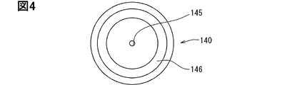
図3はこの通路部材110部分を断面図示する斜視図であるが、図3に示すように通路室112内にはケース140が配置されている。ケース140は直径が22ミリメートル程度の円筒状をしており、蓋部141と底部142を備え、内部にケース内通路143を形成している。ケース140の蓋部141にはケース内通路143のパージ空気を通路室112に戻すケース出口145が開口し(図4図示)、ケース140の側面には通路室112内のパージ空気をケース内通路143に流入させるケース入口144が開口している(図5図示)。また、ケース140の蓋部141は通路弁座115と対向し、通路弁座115との当接するケースシール面146はゴム材料製のシートが添付してある。
FIG. 3 is a perspective view showing a cross section of the
ケース140の蓋部141のケース出口145の周囲にはケース弁座147が下方に向けて突出形成されている。ケース出口145のうちケース弁座147側の位置ではケース入口144やケース内通路143に比べてパージ空気の流路面積を小さくするソニック形状としたケースソニック部148が形成されている(図3図示)。そのため、ケース140内を流れるパージ空気の流量はこのケースソニック部148により規制される。ケース140の底部142とハウジング120との間には、ケース140を通路弁座115側に付勢するケースバネ149が配置されている。ケースバネ149は通路室112内でのケース140の移動を安定させると共に、ケース140を通路弁座115側に押圧して通路弁座115のシール性を確保するものである。
A
150は樹脂製の弁体で、図6に示すように、ロット部151と頭部152とからなる。弁体の高さは15ミリメートル程度で、頭部152の直径は5ミリメートル程度である。弁体150のロット部151は可動子135の中心軸部分に圧着し、弁体150は可動子135と一体に移動する。
弁体150の頭部152は、ケース140のケース内通路143に位置し、頭部152の上面はケース弁座147と当接する弁体シール面153をなしており、この弁体シール面153にはゴム製のシート155が二次成形されている。頭部152の下面はケース140の底部142と当接する。ゴム製のシート155はこの下面にも形成されている。
The
従って、弁体150は、ケース140の蓋部141と底部142との間で移動するが、その移動距離は第1ストッパ160によって規制される。ただ、弁体150は底部142にも当接可能である。このケース140の蓋部141と底部142との間の距離が第1距離に対応する。
Therefore, the
また、弁体150のロット部151の下端は第1ストッパ160と当接するので、当接時の衝撃を緩和すべくゴム製の緩衝材154が貼付されている。
Further, since the lower end of the
第1ストッパ160は、コップ状をした可動子135と円柱形状をしたステータコア134との内側に配置され、バネ136はこの第1ストッパ160の肩部161に係止されている。弁体150の緩衝材154は第1ストッパ160の頂面162に当接する。第1ストッパ160の下端163は第2ストッパ170に当接している。従って、第1ストッパ160の位置は第2ストッパ170の位置により変移する。
The
第2ストッパ170は永久磁石であり、ストッパバネ171により第1ストッパ160の下端163に押し付けられている。そして、ストッパバネ171は下方キャップ172によって係止されている。下方キャップ172は、ハウジング120やキャップ113と同じく樹脂材料製である。
The
180は電磁石で、電磁石ボビン181上に多数回巻装された電磁石コイル182からなる。電磁石180も、ソレノイド部材130と同様、ハウジング120に二次成形されている。
電磁石180の電磁石コイル182に通電されず、電磁石180が励磁していない状態では、電磁石180と永久磁石製の第2ストッパ170とは反発せず、ストッパバネ171により押し上げられた図2の位置にある。この第2ストッパ170と第1ストッパ160の下端163とが当接する位置が第1位置P1である。電磁石180が励磁した状態では、電磁石180と永久磁石である第2ストッパ170とが反発し、第2ストッパ170は図7に示すようにストッパバネ171の付勢力に反して下方に移動する。その結果、第2ストッパ170は第1ストッパ160の下端163から離れる。この第1ストッパ160の下端163から離れた位置が第2位置P2である。
When the
次に、上記構成の流量制御弁(パージバルブ100)の組付け手順を説明する。ボビン131にコイル132を巻装し、その周囲にヨーク133とステータコア134を配置する。また、電磁石ボビン181に電磁石コイル182を巻装する。その状態で、ソレノイド部材130と電磁石180とを一体としてハウジング120に二次成形する。
Next, the procedure for assembling the flow rate control valve (purge valve 100) having the above configuration will be described. A
ケース140は蓋部141のみが別部材であり、蓋部141が装着されていない状態で、弁体150のロット部151をケース140の底部142の中心軸周りの穴に挿入する。次に、弁体150のロット部151を可動子135の中心軸穴に圧入する。なお、弁体150には予めシート155と緩衝材154が貼着されている。その後、蓋部141をケース140に溶着する。
In the
このようにして、ケース140、弁体150及び可動子135が組付けられた状態で、第1ストッパ160、バネ136及びケースバネ149と共に、図2の上方より組付けられたケース140等の部材を挿入する。ケース140等の各部材が挿入された状態で、ハウジング120の上方にキャップ113を溶着する。このキャップ113の溶着により、ハウジング120の上方部に通路室112が形成される。
In this way, with the
ハウジング120の下方からは、第2ストッパ170とストッパバネ171が挿入され、挿入された状態で下方キャップ172がハウジング120に溶着する。この下方キャップ172とキャップ113の溶着によって、パージバルブ100の組付けが終了する。
The
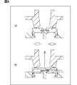
次に、上記構成の流量制御弁(パージバルブ100)の作動を説明する。電磁石180に通電されていない状態が、図2図示の第1位置P1で、第1位置P1は小流量の位置でもある。第1位置P1において、ソレノイド部材130のコイル132に通電されていない状態では、可動子135はバネ136によって上方(第2方向)に押し上げられ、弁体150の弁体シール面153がケース弁座147に当接して、ケース出口145を閉じる。バネ136の付勢力は弁体150を介してケース140にも伝わり、ケースシール面146が通路弁座115と当接して、出口114も閉じる。この状態が閉弁状態で、図8で(a)で示している。なお、閉弁状態では、ケースバネ149も付勢力として働くが、それに加えケースバネ149はケース140の傾きや軸ずれを抑制してケース140を安定させるのに用いられている。
Next, the operation of the flow rate control valve (purge valve 100) having the above configuration will be described. The state in which the
第1位置P1において、コイル132に通電されると、コイル132が励磁し、磁気ギャップ134bによって、可動子135がステータコア134側に吸引される。これにより弁体150も図2の下方(第1方向)に移動する。この可動子135と弁体150との移動は、弁体150の下端の緩衝材154が第1ストッパ160の頂面162に当接するまでで、それ以上の移動は第1ストッパ160により規制される。この際の移動距離は、弁体150の頭部152がケース140の底部142に当接するまでの距離である第1距離よりも短い。そのため、弁体150の弁体シール面153はケース弁座147から離脱して、ケース出口145を開くが、ケースシール面146が通路弁座115と当接して出口114を閉じる状態は維持される。これが、小流量開弁状態で、図8で(b)で示している。
When the
電磁石コイル182に通電されると、電磁石180が励磁し、永久磁石製の第2ストッパ170は反発して、ストッパバネ171の付勢力に抗して、下方に移動する。この状態が図7で示された第2位置P2である。第2位置P2では、第1ストッパ160はステータコア134に係止される位置まで下方(第1方向)に変移している。
When the
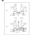
この第2位置P2でも、ソレノイド部材130のコイル132に通電されていない状態では、可動子135はバネ136によって上方(第2方向)に押し上げられ、ケース弁座147と通路弁座115とを閉じる閉弁状態となる。この閉弁状態は、図9で(a)で示しているが、状態としては図8(a)の閉弁状態と同じである。
Even in this second position P2, when the
第2位置P2において、コイル132に通電されると、コイル132が励磁し、磁気ギャップ134bによって、可動子135がステータコア134側に吸引され、弁体150も図2の下方(第1方向)に移動する。この際、第1ストッパ160は下方に移動しているので、可動子135と弁体150との移動が第1ストッパ160により規制されるまでの移動距離は、第1距離よりも長くなる。
At the second position P2, when the
そのため、弁体150の頭部152がケース140の底部142に当接した状態で、弁体150はケース140も下方(第1方向)に移動させる。その結果、弁体150の弁体シール面153はケース弁座147から離脱してケース出口145を開くと共に、ケースシール面146も通路弁座115から離脱して出口114を開く状態となる。これが、大流量開弁状態で、図9で(b)で示している。
Therefore, in a state where the
大流量開弁状態では、小流量開弁状態で流れていたケース出口145からのパージ空気に加えて、通路弁座115からのパージ空気も出口114に向かうこととなるので、流量が増大する。特に、本開示では、通路弁座115を通過して通路ソニック部116で規制される流体の流量の方が、ケース弁座147を通過してケースソニック部148で規制される流量より大きくなるように設定されている。例えば、通路弁座115とケースシール面146とで規制される流体の流量が毎分170リットル程度で、ケース弁座147と弁体シール面153とで規制される流量が毎分120リットル程度である。そのため、大流量開弁状態でのパージ空気の流量は小流量開弁状態での流量に比べて特に大きな流量とすることができている。
In the large flow rate valve open state, in addition to the purge air from the
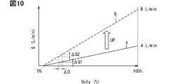
ここで、単純に流量を増すのみであれば、弁座とシール面との間を通過可能なパージ空気の流量を増やすことで解決できる。図10に示すように、線aで示す制御の最大流量Aに対し、線bで示すように最大流量がBとなるように大流量となるような設定とすれば流量Qを増やすことが可能である。 Here, if the flow rate is simply increased, it can be solved by increasing the flow rate of the purge air that can pass between the valve seat and the sealing surface. As shown in FIG. 10, it is possible to increase the flow rate Q by setting the maximum flow rate A so that the maximum flow rate becomes B as shown by the line b with respect to the maximum flow rate A of the control shown by the line a. Is.
しかしながら、単純に弁座とシール面との間を通過可能なパージ空気の流量Qを増やしたのでは、小流量域での制御特性が悪化することになる。コイル132が励磁して弁の開度が最大となるデューティ比100%(開弁状態)とコイル132が励磁せず弁が閉じているデューティ比0%(閉弁状態)との間でデューティ比制御を行う場合、小流量域で△Dのデューティ比変化が生じた際、線aの制御ではその変動が△Q1で済むのに対し、線bの制御の場合その変動は△Q2となって、流量増加に比例して圧力変動も大きくなる。特にエンジン20のアイドリング時で吸気管21の負圧が大きい時には、小流量域で大きな圧力変動が生じると、気流音や脈動音の原因となって、乗員に不快感を与えることとなる。
However, if the flow rate Q of the purge air that can pass between the valve seat and the sealing surface is simply increased, the control characteristics in the small flow rate range will deteriorate. Duty ratio between 100% duty ratio (valve open state) where the
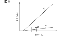
それに対し、本開示は小流量開弁状態と大流量開弁状態とで通過可能な流量Qを異ならせているので、図11に示すように、デューティ比制御を行う場合も、小流量開弁状態での制御(線c)と大流量開弁状態での制御(線d)とを異なる制御とすることができる。小流量域での制御には小流量開弁状態(線c)を用いるので、△Dのデューティ比変化に対応する流量変化は△Q1で済み、その圧力変動は相対的に小さく、大きな気流音や脈動音が発生することが抑制できる。 On the other hand, in the present disclosure, the flow rate Q that can be passed differs between the small flow rate valve open state and the large flow rate valve open state. The control in the state (line c) and the control in the large flow rate valve open state (line d) can be different controls. Since the small flow rate valve open state (line c) is used for control in the small flow rate range, the flow rate change corresponding to the duty ratio change of ΔD is only ΔQ1, the pressure fluctuation is relatively small, and a loud airflow noise is generated. And pulsating noise can be suppressed.
また、本開示では、第1位置P1から第2位置P2への切り替わりに際して、パージ空気の流量が連続して増加するようにしている。図12に線cで示すように、第1位置P1ではデューティ比0%(閉弁状態)とデューティ比100%(小流量開弁状態)との間でデューティ比制御を行い、最大流量のデューティ比100%(小流量開弁状態)で、最大流量Aを流すことができる。流量A以上のパージ空気を流す場合には、第2位置P2に切り替わり線dで示すデューティ比制御となる。 Further, in the present disclosure, the flow rate of the purge air is continuously increased when switching from the first position P1 to the second position P2. As shown by line c in FIG. 12, at the first position P1, the duty ratio is controlled between the duty ratio of 0% (valve closed state) and the duty ratio of 100% (small flow rate valve open state), and the duty of the maximum flow rate is controlled. The maximum flow rate A can be flowed at a ratio of 100% (small flow rate valve open state). When the purge air having a flow rate A or higher is flown, the duty ratio is controlled by switching to the second position P2 and indicated by the line d.
ここで、第2位置P2でデューティ比制御してもデューティ比0%(閉弁状態)とデューティ比100%(小流量開弁状態)との間でデューティ比制御を行ったのでは、デューティ比0%(閉弁状態)となればパージ空気は流れなくなる。即ち、第1位置P1から第2位置P2への切り替わりに応じて、流量Qが流量Aから流量無し(0)に変化してしまうこととなる。 Here, even if the duty ratio is controlled at the second position P2, the duty ratio is controlled between the duty ratio of 0% (valve closed state) and the duty ratio of 100% (small flow rate valve open state). When it reaches 0% (valve closed state), the purge air does not flow. That is, the flow rate Q changes from the flow rate A to no flow rate (0) in response to the switching from the first position P1 to the second position P2.
そこで、本開示では、第2位置P2でのデューティ比制御は、デューティ比0%(閉弁状態)とデューティ比100%(小流量開弁状態)との間で行うのではなく、デューティ比X%(流量Aの状態)とデューティ比100%(大流量開弁状態)との間で行うようにしている。即ち、第2位置P2にある場合には、デューティ比が0%からX%(図12で破線eで示す領域)での制御は使用しない。ここで、第2位置P2におけるデューティ比X%でのパージ空気の流量Qは、第1位置P1のデューティ比100%(小流量開弁状態)での流量Aと略同一であるように設定するので、第1位置P1から第2位置P2への切り替え時に過渡領域TRのように推移し、パージ空気の流量Qが不連続に変化することは無い。
Therefore, in the present disclosure, the duty ratio control at the second position P2 is not performed between the
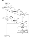
本開示の流量制御をフローチャートで示せば、図13のようになる。本フローチャートは、蒸発燃料をエンジン20へ向けて流下させる場合に開始する。パージバルブ100は、デューティ比を0%から徐々に増加していくデューティ通電によって制御される。
If the flow rate control of the present disclosure is shown by a flowchart, it will be as shown in FIG. This flowchart starts when the evaporated fuel flows down toward the
本フローチャートが開始されると、制御装置50は、ステップS100で蒸発燃料の濃度学習を行う状態か否かを判定する。ステップS100で濃度学習を行う状態であると判定すると、制御装置50は、ステップS120で電磁石180が非通電状態(第1位置P1)であるか否かを判定する。ステップS120で電磁石180が非通電状態(第1位置P1)であると判定すると、再びステップS100に戻り、ステップS100の判定処理を実行する。ステップS120で電磁石180が非通電状態でない(第2位置P2)と判定すると、ステップS125で電磁石180を非通電状態に制御して第1位置P1とし、ステップS100の判定処理を実行する。
When this flowchart is started, the
ステップS100で濃度学習を行う状態でないと判定すると、制御装置50は、ステップS110で騒音発生条件が成立するか否かを判定する。騒音発生条件は、蒸発燃料が流れる通路における圧力変動やORVRバルブ15のばたつき音の発生に伴って騒音の発生が想定できる、予め設定された条件である。騒音発生条件は、例えば、現在の車速が所定速度以下である場合に成立すると設定することができる。この場合、制御装置50は、車速センサ61によって検出される車速情報に基づいて現在の車速を取得する。車速センサ61は、車両の走行制御や車両の走行に必要な冷却系統等の制御を行う車両ECU60に車速情報を出力し、車速情報は車両ECU60から制御装置50に出力される。所定速度は、実験結果または経験則に基づいて設定されることが好ましく、騒音が走行音にかき消されて車室内の乗員に認識しにくいような車速に設定されるものとする。現在の車速が所定速度を下回っている場合に騒音発生条件の成立を設定することにより、車速が小さく走行音が小さいときに発生しやすい騒音を抑えることができる。
If it is determined in step S100 that the concentration learning is not performed, the
例えば、車両の停止時、低速走行時、エンジン20のアイドリング状態などに該当すると、制御装置50は、ステップS110で騒音発生条件が成立すると判定する。ステップS110で騒音発生条件が成立すると判定すると、ステップS120に進み、ステップS120の判定処理を実行する。
For example, when the vehicle is stopped, the vehicle is running at a low speed, the
ステップS120からステップS100に戻る流れ、ステップS125を実行後にステップS100に戻る流れは、第1位置P1でデューティ比制御する。この時は、流体の流量増加率が小さいため、蒸発燃料の濃度学習精度の向上を図ることができる。第1位置P1のモードによれば、小流量域における流量変化を小さくすることができる。さらに第1位置P1のモード時は、小流量を実施できるため、脈動の低減を図り、騒音を抑制する効果が得られる。さらに第1位置P1のモード時は、流体流量が抑えられるため、ORVRバルブ15のばたつき低減を図り、騒音を抑制する効果が得られる。
The duty ratio control of the flow returning from step S120 to step S100 and the flow returning to step S100 after executing step S125 is performed at the first position P1. At this time, since the flow rate increase rate of the fluid is small, it is possible to improve the concentration learning accuracy of the evaporated fuel. According to the mode of the first position P1, the flow rate change in the small flow rate region can be reduced. Further, in the mode of the first position P1, a small flow rate can be carried out, so that the effect of reducing pulsation and suppressing noise can be obtained. Further, in the mode of the first position P1, the fluid flow rate is suppressed, so that the effect of reducing the fluttering of the
ステップS110で騒音発生条件が成立しないと判定すると、制御装置50は、ステップS130でパージバルブ100のデューティ比が100%に達したか否かを判定する。ステップS130でデューティ比が100%に達していないと判定すると、ステップS100に戻り、ステップS100の判定処理を実行する。ステップS130でデューティ比が100%に達していると判定すると、ステップS140で電磁石180が非通電状態(第1位置P1)であるか否かを判定する。
If it is determined in step S110 that the noise generation condition is not satisfied, the
ステップS140で電磁石180が非通電状態でない(第2位置P2)と判定すると、ステップS100に戻り、ステップS100の判定処理を実行する。ステップS140で電磁石180が非通電状態(第1位置P1)であると判定すると、制御装置50は、ステップS150で電磁石180を通電状態(第2位置P2)に制御する。制御装置50は、ステップS160において、所定値であるX%にパージバルブ100のデューティ比を低下させ、ステップS100に戻る。制御装置50は、パージバルブ100のデューティ比を所定値から100%に向けて徐々に増加していく制御を実行する。ステップS150、S160の処理により、パージバルブ100が制御する流体流量を図12に示すように第1位置P1における増加率域から第2位置P2における増加率域へ滑らかに移行させることができる。第2位置P2における増加率域のモード時は、大きな流量域における流量変化を大きくすることができる。このため、騒音が発生しにくい状態において迅速に流体流量を増加でき、エンジン20の出力要求を満たす運転を実現できる。図13のフローチャートに従った制御によれば、脈動等に起因する騒音を抑制するとともに、大流量化も図れる流量制御を提供できる。
If it is determined in step S140 that the
また、制御装置50は、ステップS110で現在のエンジン20の回転数が所定回転数を下回っている場合に騒音発生条件が成立すると判定してもよい。この判定処理を採用する場合、所定回転数は、実験結果または経験則に基づいて設定されることが好ましく、騒音がエンジン音にかき消されて乗員に認識されにくいような回転数に設定されるものとする。現在のエンジン20の回転数が所定回転数を下回っている場合に騒音発生条件の成立を設定することにより、エンジン回転数が小さく静かなときに、圧力変動等に伴う音が騒音になることを抑えることができる。
Further, the
図11及び図12では、デューティ比制御では、デューティ比0%からデューティ比100%にかけて流量Qが直線的に増加する例を示した。これを弁体150の移動量(ストロークSK)と流量Qとの関係で示すと、本開示の場合には、通路室112からの出口114に通路ソニック部116を形成し、ケース内通路143からのケース出口145にケースソニック部148を形成しているので、流量Qは直線的には増加しない。図14に示すように、弁体150の移動量(ストロークSK)が所定距離に達すると、パージ空気の流量Qはソニック形状(通路ソニック部116、ケースソニック部148)に規制されて、所定距離以上離れても流体の流量増加が抑制される構造となっている。即ち、弁座(通路弁座115、ケース弁座147)の周囲長さに所定距離を乗じた断面積より、ソニック形状(通路ソニック部116、ケースソニック部148)の通路断面積の方が小さくなるので、パージ空気の流量Qはソニック形状(通路ソニック部116、ケースソニック部148)に規制される。
11 and 12 show an example in which the flow rate Q linearly increases from the duty ratio of 0% to the duty ratio of 100% in the duty ratio control. This is shown in relation to the movement amount (stroke SK) of the
なお、図14でXはデューティ比0%(閉弁状態)を示している。Nは第1位置P1におけるデューティ比100%(小流量開弁状態)を示している。そして、Zは第2位置P2における100%(大流量開弁状態)を示している。また、Lはケースソニック部148の通路断面積による流量規制の影響の方がケース弁座147の周囲長さに所定距離を乗じた通路断面積による流量規制の影響より大きくなり始める所定距離のストロークSKを示し、Mは通路ソニック部116の通路断面積による流量規制の影響の方が通路弁座115の周囲長さに所定距離を乗じた通路断面積による流量規制の影響より大きくなり始める所定距離のストロークSK示している。
In FIG. 14, X indicates a duty ratio of 0% (valve closed state). N indicates a duty ratio of 100% (small flow rate valve open state) at the first position P1. And Z indicates 100% (large flow rate valve open state) in the second position P2. Further, in L, the influence of the flow rate regulation by the passage cross-sectional area of the case
従って、第1位置P1では、XとLとの間のストロークSKはストロークSKに応じて流量Qは略直線的に増加するが、LとNとの間のストロークでは略一定の流量Qとなる。また、第2位置P2では、XとLとの間及びYとMとの間はストロークSKに応じて流量Qは略直線的に増加するが、LとYとの間及びMとZでは略一定の流量Qとなる。 Therefore, at the first position P1, the stroke SK between X and L increases the flow rate Q substantially linearly according to the stroke SK, but the stroke between L and N has a substantially constant flow rate Q. .. Further, at the second position P2, the flow rate Q increases substantially linearly between X and L and between Y and M according to the stroke SK, but is omitted between L and Y and between M and Z. The flow rate Q becomes constant.
第1位置P1では、弁体150が第1方向(図2の下方)に第1距離以上移動する前に弁体150のロット部151の下端が第1ストッパ160と当接するので、実際にはゴム製の緩衝材154が第1ストッパ160と当接するので(図14のN)、弁体150は第1距離(図14のY)まで移動することが出来ない。それに対し、第2位置P2では、弁体150の頭部152がケース140の底部142と当接する第1距離まで移動しても、緩衝材154が第1ストッパ160と当接することは無く、弁体150はZの位置まで移動して第1ストッパ160に当接する。
At the first position P1, the lower end of the
第1位置P1での最大ストロークSK(N)が第1距離(Y)より短いことは、本開示のソレノイド部材130のコイル132のデューティ比制御において、第2位置P2におけるデューティ比X%を定めるのに有用である。即ち、デューティ比X%は、第1位置P1におけるデューティ比100%(小流量開弁状態)の流量Aと略同じ流量Qが得られるように選定する。これは、可動子135や弁体150の移動量(ストロークSK)であればLからYの間であればよく、微小誤差を許容できる。
The fact that the maximum stroke SK (N) at the first position P1 is shorter than the first distance (Y) determines the duty ratio X% at the second position P2 in the duty ratio control of the
本開示ではソニック形状(通路ソニック部116、ケースソニック部148)を用いているので、要求される流量Qが小流量であっても、大流量であっても、共に最大ストロークSK(N、Z)では、ソニック形状(通路ソニック部116、ケースソニック部148)で流量Qを規定することができる。デューティ比制御は単位時間(例えば、0.1秒)内で、ストローク最大の状態(N、Z)と弁体150が弁座(通路弁座115、ケース弁座147)を閉じた状態(X)との切り替えを多数回行うので、最大ストローク(N、Z)の流量が一定であることは制御性を向上させる。尤も、低デューティ比の場合は可動子135や弁体150の移動量は流量特性に影響を与える。
Since the sonic shape (passage
なお、上述したのは本開示の望ましい例であるが、本開示は種々に変更可能である。寸法や材質は要求仕様に応じて適宜変更できる。 Although the above is a desirable example of the present disclosure, the present disclosure can be changed in various ways. Dimensions and materials can be changed as appropriate according to the required specifications.
第2ストッパ170として、上述の例では永久磁石を用い電磁石180との反発を利用したが、電磁石180に吸引されるような配置としても良い。電磁石180との吸引を利用する場合には、第2ストッパ170は永久磁石ではなく、鉄等の磁性材としてもよい。
As the
また、上述の例では、ソニック形状を通路ソニック部116とケースソニック部148の両方に形成したが、いずれか一方としても良く、いずれにも形成しないとする態様もありうる。ソニック形状を形成する場合でも、図14に示した所定距離(L、M)は一例であり、より長いストロークとすることも可能である。
Further, in the above example, the sonic shape is formed in both the passage
ケース140の形状も上述した円筒形状以外の形状も可能である。ケース入口144の形成位置も側面以外とすることも可能であり、ケース入口144の数を複数にしてもよい。ケースバネ149はケース140を安定化するうえで望ましいが、必要に応じて廃止することの可能である。
The shape of the
また、上述の例では、第1位置P1でも第2位置P2でも弁体150は第1ストッパ160に当接する構造としていたが、第2位置P2では通路弁座115を開いておればよく、必ずしも第1ストッパ160に当接する必要はない。
Further, in the above example, the
また、上述の例では本開示の流量制御弁をパージバルブ100として用いたが、パージバルブ100以外の用途に用いることは勿論可能である。
Further, in the above example, the flow rate control valve of the present disclosure is used as the
100 パージバルブ
110 通路部材
111 入口
114 出口
115 通路弁座
130 ソレノイド部材
132 コイル
134 ステータコア
135 可動子
140 ケース
144 ケース入口
145 ケース出口
147 ケース弁座
150 弁体
160 第1ストッパ
170 第2ストッパ
180 電磁石
100
Claims (8)
前記通路室内に配設され、前記通路室内の流体が流入するケース入口と、流体を前記通路室に流出するケース出口と、このケース出口と前記ケース入口との間に形成され流体が通過するケース内通路と、このケース内通路の前記ケース出口周囲に突出形成されたケース弁座と、前記通路弁座と当接するケースシール面とを備えるケースと、
通電時に励磁するコイルと、このコイルの磁気回路を形成するヨークと、このヨークと共に前記コイルの磁気回路を形成するステータコアと、このステータコアと磁気ギャップを介して配置され前記コイルの励磁時に第1方向に移動する可動子と、この可動子を前記第1方向とは逆の第2方向に付勢するバネとを備えるソレノイド部材と、
前記可動子と共に移動して、前記可動子が前記第1方向に移動していない状態で前記ケース弁座に弁体シール面が当接すると共に前記ケースシール面を前記通路弁座に当接させ、前記可動子が前記第1方向に第1距離以内で移動した状態で前記ケース弁座から前記弁体シール面が離脱すると共に前記ケースシール面を前記通路弁座に当接させた状態を維持し、前記可動子が前記第1方向に前記第1距離以上移動した状態では前記ケース弁座から前記弁体シール面が離脱すると共に前記ケースシール面も前記通路弁座から離脱させる弁体と、
この弁体の前記第1方向の移動を規制すると共に自身は前記第1方向に移動可能な第1ストッパと、
この第1ストッパの前記第1方向の移動を規制すると共に自身は前記第1方向に移動可能な第2ストッパと、
この第2ストッパの位置を、前記弁体の前記第1距離未満での移動を許容し前記第1距離以上に前記弁体が移動する際には前記弁体が前記第1ストッパに当接して前記弁体の移動を規制する第1位置(P1)と、前記第1距離以上に前記弁体が移動した際にも前記弁体の移動を許容する第2位置(P2)とに切り替える電磁石とを備える、
流量制御弁。 An inlet through which the fluid flows in, an outlet through which the fluid flows out, a passage chamber formed between the outlet and the inlet through which the fluid passes, and a passage valve seat protruding around the outlet of the passage chamber. The passage members to be provided and
A case arranged in the aisle chamber where the fluid in the aisle chamber flows in, a case outlet through which the fluid flows out into the aisle chamber, and a case formed between the case outlet and the case inlet through which the fluid passes. A case including an inner passage, a case valve seat projecting around the case outlet of the case inner passage, and a case seal surface in contact with the passage valve seat.
A coil that excites when energized, a yoke that forms the magnetic circuit of this coil, a stator core that forms the magnetic circuit of the coil together with this yoke, and a stator core that is arranged via a magnetic gap and is arranged in the first direction when the coil is excited. A solenoid member including a mover that moves to and a spring that urges the mover in a second direction opposite to the first direction.
It moves together with the mover, and the valve body seal surface comes into contact with the case valve seat and the case seal surface comes into contact with the passage valve seat in a state where the mover does not move in the first direction. With the mover moving in the first direction within the first distance, the valve body sealing surface is separated from the case valve seat, and the case sealing surface is maintained in contact with the passage valve seat. When the mover is moved in the first direction by the first distance or more, the valve body sealing surface is detached from the case valve seat and the case sealing surface is also detached from the passage valve seat.
The first stopper, which regulates the movement of the valve body in the first direction and can move itself in the first direction,
The second stopper, which regulates the movement of the first stopper in the first direction and can move itself in the first direction,
The position of the second stopper allows the valve body to move less than the first distance, and when the valve body moves beyond the first distance, the valve body comes into contact with the first stopper. An electromagnet that switches between a first position (P1) that regulates the movement of the valve body and a second position (P2) that allows the movement of the valve body even when the valve body moves beyond the first distance. Equipped with
Flow control valve.
ことを特徴とする請求項1記載の流量制御弁。 The flow rate according to claim 1, wherein the flow rate of the fluid regulated by the passage valve seat and the case seal surface is larger than the flow rate regulated by the case valve seat and the valve body seal surface. Control valve.
ことを特徴とする請求項1若しくは2に記載の流量制御弁。 The outlet of the passage member is formed in a sonic shape that regulates the flow rate of the fluid, and when the distance between the case seal surface and the passage valve seat is a predetermined distance in the first direction, the flow rate of the fluid has this sonic shape. The flow rate control valve according to claim 1 or 2, wherein the increase in the flow rate of the fluid is suppressed even if the distance is more than a predetermined distance.
ことを特徴とする請求項1ないし3のいずれかに記載の流量制御弁。 The case outlet of the case is formed in a sonic shape that regulates the flow rate of the fluid, and when the distance between the valve body sealing surface and the case valve seat is a predetermined distance in the first direction, the flow rate of the fluid is this sonic. The flow rate control valve according to any one of claims 1 to 3, wherein the flow rate control valve is regulated by a shape and the increase in the flow rate of the fluid is suppressed even if the distance is more than a predetermined distance.
前記電磁石の励磁時には前記電磁石と反発して前記第2位置(P2)となり、前記電磁石の非励磁時には前記ストッパバネの付勢力で前記第1位置(P1)となる
ことを特徴とする請求項1ないし4のいずれかに記載の流量制御弁。 The second stopper is composed of a permanent magnet and includes a stopper spring that urges the second stopper in the first direction.
Claims 1 to 1, wherein when the electromagnet is excited, it repels the electromagnet and becomes the second position (P2), and when the electromagnet is not excited, it becomes the first position (P1) by the urging force of the stopper spring. The flow rate control valve according to any one of 4.
前記ケース入口は前記ケースの側面に形成され、
前記ケース出口は前記ケースの蓋面に形成され、
前記弁体が前記第1距離以上前記第1方向に移動した際には、前記弁体が前記ケースの底面と係合する
ことを特徴とする請求項1ないし5のいずれかに記載の流量制御弁。 The case has a covered bottomed cylindrical shape that forms a passage inside the case.
The case entrance is formed on the side surface of the case.
The case outlet is formed on the lid surface of the case and is formed.
The flow rate control according to any one of claims 1 to 5, wherein when the valve body moves in the first direction by the first distance or more, the valve body engages with the bottom surface of the case. valve.
ことを特徴とする請求項1ないし6のいずれかに記載の流量制御弁。 The passage member has a case spring for urging the case in the second direction in which the case sealing surface abuts on the passage valve seat, according to claims 1 to 6. The flow control valve according to any one.
前記第2ストッパの位置が前記第1位置(P1)にある状態ではデューティ比が0%と100%との間でデューティ比制御を行い、
前記第2ストッパの位置が前記第2位置(P2)にある状態ではデューティ比が所定値X%と100%との間でデューティ比制御を行い、
前記第2ストッパの位置が前記第1位置(P1)にある状態での100%のデューティ比制御で流れる流体の流量が、前記第2ストッパの位置が前記第2位置(P2)にある状態でのデューティ比が所定値X%のデューティ比制御で流れる流体の流量と略同じである
ことを特徴とする請求項1ないし7のいずれかに記載の流量制御弁。 The solenoid member controls the duty ratio between the excited state of the coil and the non-excited state of the coil.
When the position of the second stopper is in the first position (P1), the duty ratio is controlled between 0% and 100%.
When the position of the second stopper is in the second position (P2), the duty ratio is controlled between the predetermined value X% and 100%.
The flow rate of the fluid flowing under 100% duty ratio control when the position of the second stopper is in the first position (P1) is in the state where the position of the second stopper is in the second position (P2). The flow rate control valve according to any one of claims 1 to 7, wherein the duty ratio of the above is substantially the same as the flow rate of the fluid flowing under the duty ratio control of a predetermined value X%.
Priority Applications (1)
| Application Number | Priority Date | Filing Date | Title |
|---|---|---|---|
| JP2020215579A JP2022101153A (en) | 2020-12-24 | 2020-12-24 | Flow control valve |
Applications Claiming Priority (1)
| Application Number | Priority Date | Filing Date | Title |
|---|---|---|---|
| JP2020215579A JP2022101153A (en) | 2020-12-24 | 2020-12-24 | Flow control valve |
Publications (1)
| Publication Number | Publication Date |
|---|---|
| JP2022101153A true JP2022101153A (en) | 2022-07-06 |
Family
ID=82271558
Family Applications (1)
| Application Number | Title | Priority Date | Filing Date |
|---|---|---|---|
| JP2020215579A Pending JP2022101153A (en) | 2020-12-24 | 2020-12-24 | Flow control valve |
Country Status (1)
| Country | Link |
|---|---|
| JP (1) | JP2022101153A (en) |
-
2020
- 2020-12-24 JP JP2020215579A patent/JP2022101153A/en active Pending
Similar Documents
| Publication | Publication Date | Title |
|---|---|---|
| JP5772881B2 (en) | solenoid valve | |
| JP4203906B2 (en) | Solenoid valve and evaporative fuel processing system using the same | |
| US7591281B2 (en) | Electromagnetic valve | |
| US6681746B1 (en) | Regulated linear purge solenoid valve | |
| JP6028764B2 (en) | solenoid valve | |
| US20150151629A1 (en) | Fuel storage device | |
| US20060185735A1 (en) | Electromagnetic combination valve | |
| JP5689983B2 (en) | solenoid valve | |
| CN112219052B (en) | Fluid control valve and evaporated fuel treatment device | |
| JP2022101153A (en) | Flow control valve | |
| JP5952067B2 (en) | Fluid control valve device | |
| JP6977797B2 (en) | Purge control valve device | |
| US6015133A (en) | Fuel vapor managment valve | |
| US11028790B2 (en) | Purge control valve device | |
| KR101348570B1 (en) | Purge control solenoid valve with improve the performance | |
| CN112539291B (en) | Purge control valve device | |
| JP7172933B2 (en) | Purge control valve device | |
| JP6919459B2 (en) | Flow control device | |
| JP7192728B2 (en) | Purge control valve device | |
| JP6930438B2 (en) | Flow control device | |
| JP2011179662A (en) | Solenoid valve | |
| JP7006553B2 (en) | Purge control valve | |
| JP2020133540A (en) | Flow control device | |
| JP7192727B2 (en) | Purge control valve device | |
| JP2020190222A (en) | Flow rate adjusting device |