以下、図面を参照して実施の形態について説明する。各図において共通または対応する要素には、同一の符号を付して、説明を簡略化または省略する。なお、本開示で角度に言及した場合において、和が360°となる優角と劣角とがあるときには原則として劣角の角度を指すものとし、和が180°となる鋭角と鈍角とがある場合には原則として鋭角の角度を指すものとする。以下の説明では、塵埃とその他のゴミとは、まとめて単に「塵埃」と呼ばれる。塵埃が混じった空気は、「含塵空気」と呼ばれる。塵埃が取り除かれた空気は、「清浄空気」と呼ばれる。また、以下に示す実施の形態に示した構成は、本開示の内容の一例を示すものであり、別の公知の技術と組み合わせることも可能であるし、本開示に記載の内容を組み合わせることも可能である。また、本開示の要旨を逸脱しない範囲で、構成の一部を省略、変更することも可能である。
Hereinafter, embodiments will be described with reference to the drawings. The common or corresponding elements in each figure are designated by the same reference numerals to simplify or omit the description. When the angle is referred to in the present disclosure, when there is a superior angle and an obtuse angle in which the sum is 360 °, in principle, the angle of the inferior angle is referred to, and there are an acute angle and an obtuse angle in which the sum is 180 °. In some cases, it refers to an acute angle in principle. In the following description, dust and other debris are collectively referred to simply as "dust". Air mixed with dust is called "dust-containing air". The air from which dust has been removed is called "clean air". Further, the configuration shown in the embodiment shown below shows an example of the contents of the present disclosure, and can be combined with another known technique, or the contents described in the present disclosure can be combined. It is possible. Further, it is possible to omit or change a part of the configuration without departing from the gist of the present disclosure.
実施の形態1.
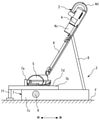
図1は、実施の形態1による掃除機システム1を示す斜視図である。図2は、図1に示す掃除機システム1が備える掃除機2を示す斜視図である。図3は、実施の形態1による保持装置3を示す斜視図である。図4は、実施の形態1による掃除機システム1のブロック図である。
Embodiment 1.
FIG. 1 is a perspective view showing a vacuum cleaner system 1 according to the first embodiment. FIG. 2 is a perspective view showing a vacuum cleaner 2 included in the vacuum cleaner system 1 shown in FIG. FIG. 3 is a perspective view showing the holding device 3 according to the first embodiment. FIG. 4 is a block diagram of the vacuum cleaner system 1 according to the first embodiment.
これらの図に示されるように、掃除機システム1は、掃除機2と保持装置3とを備える。掃除機2は、掃除機本体4と、吸込具5と、管体6とを備える。掃除機本体4は、吸引力を発生させる電動送風機4aと、電動送風機4aに電力を供給するバッテリ4bを内蔵する。吸込具5の底面には、被清掃面から塵埃を吸い込むための吸込口が形成されている。管体6は、吸込具5と掃除機本体4との間を接続する。吸込具5から吸い込まれた含塵空気は、管体6内の風路を通って掃除機本体4に流入する。掃除機本体4は、含塵空気から塵埃を除去して捕集する集塵部4cを有する。集塵部4cにより塵埃が取り除かれた清浄空気は、電動送風機4aを通過して外部へ排出される。
As shown in these figures, the vacuum cleaner system 1 includes a vacuum cleaner 2 and a holding device 3. The vacuum cleaner 2 includes a vacuum cleaner main body 4, a suction tool 5, and a tube body 6. The vacuum cleaner main body 4 includes an electric blower 4a that generates suction force and a battery 4b that supplies electric power to the electric blower 4a. A suction port for sucking dust from the surface to be cleaned is formed on the bottom surface of the suction tool 5. The pipe body 6 connects between the suction tool 5 and the vacuum cleaner main body 4. The dust-containing air sucked from the suction tool 5 flows into the vacuum cleaner main body 4 through the air passage in the pipe body 6. The vacuum cleaner main body 4 has a dust collecting unit 4c that removes and collects dust from dust-containing air. The clean air from which the dust has been removed by the dust collecting unit 4c passes through the electric blower 4a and is discharged to the outside.
掃除機本体4と吸込具5と管体6を備えた掃除機2とは例えばスティック型の掃除機である。また、図示の例に限らず、掃除機は可撓性のあるホースを備えていてもよい。この場合、ホースは管体と掃除機本体との間を接続する。吸込具から吸い込まれた含塵空気は管体内及びホース内の風路を通って掃除機本体に進入する。掃除機本体と吸込具と管体とホースを備えた掃除機とは例えばキャニスタ型の掃除機である。また、掃除機は掃除機本体と吸込具が着脱自在なものであっても良い。また、吸込口は掃除機の底面に設けられていてもよい。
The vacuum cleaner 2 provided with the vacuum cleaner main body 4, the suction tool 5, and the tube body 6 is, for example, a stick-type vacuum cleaner. Further, the vacuum cleaner may be provided with a flexible hose, not limited to the illustrated example. In this case, the hose connects between the tube and the vacuum cleaner body. The dust-containing air sucked from the suction tool enters the vacuum cleaner body through the air passage in the pipe and the hose. A vacuum cleaner provided with a vacuum cleaner body, a suction tool, a tube body, and a hose is, for example, a canister type vacuum cleaner. Further, the vacuum cleaner may have a removable vacuum cleaner body and a suction tool. Further, the suction port may be provided on the bottom surface of the vacuum cleaner.
使用者が手で握る部分であるハンドル4dが掃除機本体4に設けられている。吸込具5の前後方向は、図1及び図2中の矢印で示す方向に相当する。ハンドル4dを握って掃除機2の吸込具5により床面を清掃するときに使用者にとって前となる方向が吸込具5の前方に相当し、当該使用者にとって後ろとなる方向が吸込具5の後方に相当する。管体6が掃除機本体4から取り外し可能でもよい。管体6を取り外した状態の掃除機本体4をハンディ型掃除機として使用可能でもよい。
A handle 4d, which is a part held by the user, is provided on the vacuum cleaner main body 4. The front-back direction of the suction tool 5 corresponds to the direction indicated by the arrow in FIGS. 1 and 2. When the floor surface is cleaned by the suction tool 5 of the vacuum cleaner 2 by grasping the handle 4d, the front direction for the user corresponds to the front of the suction tool 5, and the rear direction for the user is the suction tool 5. Corresponds to the rear. The tube body 6 may be removable from the vacuum cleaner body 4. The vacuum cleaner main body 4 with the tube body 6 removed may be used as a handheld vacuum cleaner.
例えば、吸込具5は吸込口体と関節を備える。関節は例えば吸込口体に対して管体6を上下方向に回転させる第一の回転軸を中心に回転する。関節は例えば吸込口体に対して管体6を左右方向に回転させる第二の回転軸を中心に回転する。このような二つの回転軸を中心に回転させることで、ハンドル4dの高さを変えても、吸込口体の姿勢は変わらない。例えば、第一の回転軸がない場合は、ハンドル4dの高さを変えると、吸込口体と被清掃面との姿勢が変わってしまう。しかし第一回転軸を中心に回転することで、吸込口体と被清掃面との姿勢が変わらない。このため、ハンドル4dの高さが変化しても被清掃面の塵埃を吸引することができる。図1及び図2中の矢印で示す前後方向は掃除機システム1または保持装置3または掃除機2の前後方向に相当するものでもある。使用者が掃除機2を用いて掃除をする際、ハンドル4dは吸込具5より後方に配置される。
For example, the suction tool 5 includes a suction port and a joint. The joint rotates, for example, about a first rotation axis that rotates the tube body 6 in the vertical direction with respect to the suction port body. The joint rotates about, for example, a second rotation axis that rotates the tube body 6 in the left-right direction with respect to the suction port body. By rotating around these two rotation axes, the posture of the suction port does not change even if the height of the handle 4d is changed. For example, if there is no first rotation axis, changing the height of the handle 4d will change the posture of the suction port and the surface to be cleaned. However, by rotating around the first rotation axis, the postures of the suction port and the surface to be cleaned do not change. Therefore, even if the height of the handle 4d changes, dust on the surface to be cleaned can be sucked. The front-back direction indicated by the arrows in FIGS. 1 and 2 also corresponds to the front-back direction of the vacuum cleaner system 1, the holding device 3, or the vacuum cleaner 2. When the user cleans using the vacuum cleaner 2, the handle 4d is arranged behind the suction tool 5.
保持装置3は、掃除機2の非清掃中に掃除機2の位置を保つ。すなわち、保持装置3は、非清掃状態の掃除機2をセットし、掃除機2の姿勢を保つものである。また保持装置3は掃除機2を保持または支持するものである。保持装置3により掃除機2を保持または支持することで、掃除機2の位置及び姿勢が保たれる。掃除機2は、清掃が行われる際に保持装置3から取り外される。掃除機2は、清掃が終了した後に保持装置3にセットされる。例えば、保持装置3は、居室の床面に置かれる。保持装置3は、掃除機2のバッテリ4bを充電する充電台としての機能を有する。保持装置3は、基体7と、支持部8とを備える。基体7は、保持装置3の中で最も下方に配置される。基体7は、載置部7aを有する。載置部7aとは吸込具5を置く場所である。掃除機2を保持装置3にセットすると、載置部7aの上に吸込具5が載置された状態になる。吸込具5は、その底面から突出する車輪を有していてもよい。その場合、当該車輪が載置部7aに接する。支持部8は、基体7から上方に向かって突出する。支持部8は、掃除機本体4及び管体6の少なくとも一方に接することで、掃除機2の位置を保つことができる。本実施の形態では、保持装置3に掃除機2がセットされると、管体6の長手軸が鉛直線に平行になる。本実施の形態であれば、支持部8を備えたことで、掃除機2を所定の位置に確実に保つことが可能となる。
The holding device 3 keeps the position of the vacuum cleaner 2 while the vacuum cleaner 2 is not cleaned. That is, the holding device 3 sets the vacuum cleaner 2 in the non-cleaning state and keeps the posture of the vacuum cleaner 2. Further, the holding device 3 holds or supports the vacuum cleaner 2. By holding or supporting the vacuum cleaner 2 by the holding device 3, the position and posture of the vacuum cleaner 2 are maintained. The vacuum cleaner 2 is removed from the holding device 3 when cleaning is performed. The vacuum cleaner 2 is set in the holding device 3 after the cleaning is completed. For example, the holding device 3 is placed on the floor of the living room. The holding device 3 has a function as a charging stand for charging the battery 4b of the vacuum cleaner 2. The holding device 3 includes a substrate 7 and a support portion 8. The substrate 7 is arranged at the lowest position in the holding device 3. The substrate 7 has a mounting portion 7a. The mounting portion 7a is a place where the suction tool 5 is placed. When the vacuum cleaner 2 is set in the holding device 3, the suction tool 5 is placed on the mounting portion 7a. The suction tool 5 may have wheels protruding from its bottom surface. In that case, the wheel comes into contact with the mounting portion 7a. The support portion 8 projects upward from the substrate 7. The support portion 8 can maintain the position of the vacuum cleaner 2 by being in contact with at least one of the vacuum cleaner main body 4 and the pipe body 6. In the present embodiment, when the vacuum cleaner 2 is set in the holding device 3, the longitudinal axis of the tubular body 6 becomes parallel to the vertical line. In the present embodiment, the provision of the support portion 8 makes it possible to reliably keep the vacuum cleaner 2 in a predetermined position.
掃除機2が保持装置3に取り付けられる際、掃除機本体4及び管体6の少なくとも一方は、支持部8に保持される。吸込具5は、保持装置3の基体7に支持される。この際、吸込具5の後端は、管体6と掃除機本体4より後方側に配置される。掃除機本体4の重心は、管体6の内部風路より前方側となる。本実施の形態では、掃除機本体4の重心は、管体6よりも掃除機本体4の前方側となる。また、吸込口は略長方形形状を呈している。吸込口は前後方向に対して垂直な方向に延びる開口である。
When the vacuum cleaner 2 is attached to the holding device 3, at least one of the vacuum cleaner main body 4 and the pipe body 6 is held by the support portion 8. The suction tool 5 is supported by the substrate 7 of the holding device 3. At this time, the rear end of the suction tool 5 is arranged on the rear side of the pipe body 6 and the vacuum cleaner main body 4. The center of gravity of the vacuum cleaner body 4 is on the front side of the internal air passage of the pipe body 6. In the present embodiment, the center of gravity of the vacuum cleaner main body 4 is on the front side of the vacuum cleaner main body 4 with respect to the pipe body 6. Further, the suction port has a substantially rectangular shape. The suction port is an opening extending in a direction perpendicular to the front-rear direction.
支持部8で管体6を支持する場合は例えば、管体6の上部を支持してもよく、管体6の下部を支持してもよい。または、掃除機本体4の下部を支持部8で支持してもよいし、掃除機本体4の上部を支持部8で支持してもよい。また、支持部8で掃除機2を支持する場合、実施の形態では掃除機本体4及び管体6の少なくとも一方の前部を支持しているが、掃除機本体4及び管体6の少なくとも一方の後部を支持してもよい。また、載置部7aは、吸込具5の前端に接することにより、吸込具5を位置決めする突出部を有している。
When the tube body 6 is supported by the support portion 8, for example, the upper portion of the tube body 6 may be supported or the lower portion of the tube body 6 may be supported. Alternatively, the lower portion of the vacuum cleaner main body 4 may be supported by the support portion 8, or the upper portion of the vacuum cleaner main body 4 may be supported by the support portion 8. Further, when the vacuum cleaner 2 is supported by the support portion 8, the front portion of at least one of the vacuum cleaner main body 4 and the pipe body 6 is supported in the embodiment, but at least one of the vacuum cleaner main body 4 and the pipe body 6 is supported. The rear may be supported. Further, the mounting portion 7a has a protruding portion for positioning the suction tool 5 by contacting the front end of the suction tool 5.
図3に示すように、保持装置3は、紫外線照射部9を備える。紫外線照射部9は吸込具5の底部に向けて紫外線を照射するように構成されている。紫外線照射部9は光線を照射または出射する光源を備える。光源は載置部7aの最上部よりも低い位置に設けられていてもよい。光線はメインの波長またはピークの波長が紫外線である。紫外線とは一般に10nm~400nmの波長の不可視光線の電磁波である。光線の少なくとも一部は鉛直方向上方に照射される。光源の光軸は例えば、鉛直方向に平行に配置される。光源の光軸は例えば、水平方向に平行に配置されてもよい。光源の光軸は例えば、水平方向に平行かつ前後方向に垂直に配置されてもよい。
As shown in FIG. 3, the holding device 3 includes an ultraviolet irradiation unit 9. The ultraviolet irradiation unit 9 is configured to irradiate the bottom of the suction tool 5 with ultraviolet rays. The ultraviolet irradiation unit 9 includes a light source that irradiates or emits light rays. The light source may be provided at a position lower than the uppermost portion of the mounting portion 7a. The main wavelength or peak wavelength of light rays is ultraviolet light. Ultraviolet rays are generally electromagnetic waves of invisible light having a wavelength of 10 nm to 400 nm. At least a part of the light beam is emitted upward in the vertical direction. The optical axis of the light source is arranged parallel to the vertical direction, for example. The optical axis of the light source may be arranged in parallel in the horizontal direction, for example. The optical axis of the light source may be arranged, for example, parallel to the horizontal direction and perpendicular to the front-back direction.
掃除機2が保持装置3に支持された状態で、光源は掃除機2及び吸込具5の最低部より低い位置に配置される。また、掃除機2が保持装置3に支持された状態で、光源は吸込具5の前端部より後方に配置される。また、掃除機2が保持装置3に支持された状態で、光源は吸込具5の後端部より前方に配置される。また、光源は複数備えられていてもよい。その場合、例えば、前後方向に垂直な方向に一直線に複数の光源が配置されていてもよい。紫外線照射部9は、載置部7aの上面に設けられた出射面を有する。吸込具5が載置部7aに載置された状態で、吸込具5の底面が載置部7aの上面に向かい合う。この状態で、紫外線照射部9の出射面から上に向けて紫外線が出射することで、吸込具5の底面に紫外線が照射される。また、出射面は載置部7aとは異なる材料で構成されていてもよく、載置部7aの一部でなくてもよい。また、出射面は紫外線照射部9の一部であってもよい。例えば、出射面は載置面と平行に配置される。例えば出射面は載置面と同等の高さに配置される。例えば出射面は載置面と同等もしくは載置面より低い位置に配置される。例えば、載置部7aはABSあるいはPP等の汎用材で構成されていてもよい。また、出射面は紫外線透過性の高い材料で構成されていてもよい。ABSあるいはPPは紫外線透過性が低い材料である。ABSあるいはPPを光源の上方に配置した場合、紫外線が吸収されてしまい、紫外線が吸込具5に照射されにくくなる。出射面は例えば、載置部7aより紫外線透過性が高い材料で構成される。例えば、上面視にて、出射面の大部分は露出した位置に配置される。大部分とは例えば50%以上である。大部分とは例えば、80%以上である。出射面の上方かつ吸込具5との間には紫外線透過率が低い材料が間に介在していないことが望ましい。但し、出射面を載置部7aに固定するため等の理由から出射面の上部に載置部7aが配置されていてもよい。例えば、出射面の外周かつ直上に載置部7aの一部が配置されていてもよい。出射面は例えば、少なくとも光源の直上に配置される。出射面が載置部7aと同等または低い位置にあることで、出射面が吸込具5等により傷つき、透過率が低下することをより確実に防止できる。
With the vacuum cleaner 2 supported by the holding device 3, the light source is arranged at a position lower than the lowest portion of the vacuum cleaner 2 and the suction tool 5. Further, with the vacuum cleaner 2 supported by the holding device 3, the light source is arranged behind the front end portion of the suction tool 5. Further, the light source is arranged in front of the rear end portion of the suction tool 5 while the vacuum cleaner 2 is supported by the holding device 3. Further, a plurality of light sources may be provided. In that case, for example, a plurality of light sources may be arranged in a straight line in a direction perpendicular to the front-rear direction. The ultraviolet irradiation unit 9 has an emission surface provided on the upper surface of the mounting unit 7a. With the suction tool 5 mounted on the mounting portion 7a, the bottom surface of the suction tool 5 faces the upper surface of the mounting portion 7a. In this state, the ultraviolet rays are emitted upward from the emission surface of the ultraviolet irradiation unit 9, so that the bottom surface of the suction tool 5 is irradiated with the ultraviolet rays. Further, the exit surface may be made of a material different from that of the mounting portion 7a, and may not be a part of the mounting portion 7a. Further, the emission surface may be a part of the ultraviolet irradiation unit 9. For example, the exit surface is arranged parallel to the mounting surface. For example, the exit surface is arranged at the same height as the mounting surface. For example, the exit surface is arranged at a position equal to or lower than the mounting surface. For example, the mounting portion 7a may be made of a general-purpose material such as ABS or PP. Further, the exit surface may be made of a material having high ultraviolet transparency. ABS or PP is a material with low ultraviolet transparency. When the ABS or PP is arranged above the light source, the ultraviolet rays are absorbed, and the ultraviolet rays are less likely to be irradiated to the suction tool 5. The emission surface is made of, for example, a material having higher ultraviolet transparency than the mounting portion 7a. For example, in top view, most of the exit surface is placed in an exposed position. Most are, for example, 50% or more. Most are, for example, 80% or more. It is desirable that a material having a low ultraviolet transmittance is not interposed above the emission surface and between the suction tool 5. However, the mounting portion 7a may be arranged on the upper part of the emitting surface for reasons such as fixing the exiting surface to the mounting portion 7a. For example, a part of the mounting portion 7a may be arranged on the outer periphery and directly above the exit surface. The exit surface is, for example, arranged at least directly above the light source. Since the emission surface is at the same position as or lower than the mounting portion 7a, it is possible to more reliably prevent the emission surface from being damaged by the suction tool 5 or the like and the transmittance from being lowered.
図示の例において、載置部7aの上面は、載置部7a以外の基体7の上面よりも低い位置にある。このような例に限らず、載置部7aの上面が、載置部7a以外の基体7の上面と同じ高さの位置に形成されていてもよい。また、載置部7aの上面が、載置部7a以外の基体7の上面より高い位置に配置されていてもよい。
In the illustrated example, the upper surface of the mounting portion 7a is located at a position lower than the upper surface of the substrate 7 other than the mounting portion 7a. Not limited to such an example, the upper surface of the mounting portion 7a may be formed at the same height as the upper surface of the substrate 7 other than the mounting portion 7a. Further, the upper surface of the mounting portion 7a may be arranged at a position higher than the upper surface of the substrate 7 other than the mounting portion 7a.
清掃中に被清掃面の菌あるいはウイルスが吸込具5の底面に付着する可能性がある。本実施の形態であれば、清掃後に掃除機2を保持装置3にセットすることで、紫外線照射部9から吸込具5の底面に紫外線を照射できる。紫外線の照射により、吸込具5の底面は除菌される。それゆえ、次に清掃するときに、吸込具5が清潔になっているので、菌あるいはウイルスが室内に広まることを確実に防止できる。それゆえ、室内の衛生性を向上することが可能となる。なお、本開示において「殺菌」あるいは「除菌」とは、菌あるいはウイルスの数が減ること、または、少なくとも一部の菌あるいはウイルスが不活化されることに相当する。本開示において「菌」とは、バクテリア(真正細菌)あるいはアーキア(古細菌)に相当する。
During cleaning, bacteria or viruses on the surface to be cleaned may adhere to the bottom surface of the suction tool 5. In the present embodiment, by setting the vacuum cleaner 2 in the holding device 3 after cleaning, the bottom surface of the suction tool 5 can be irradiated with ultraviolet rays from the ultraviolet irradiation unit 9. The bottom surface of the suction tool 5 is sterilized by irradiation with ultraviolet rays. Therefore, the next time the suction device 5 is cleaned, the suction tool 5 is clean, so that it is possible to surely prevent the spread of bacteria or viruses into the room. Therefore, it is possible to improve the hygiene of the room. In the present disclosure, "sterilization" or "eradication" corresponds to a decrease in the number of bacteria or viruses, or inactivation of at least a part of the bacteria or viruses. In the present disclosure, "bacteria" corresponds to bacteria (eubacteria) or archaea (archaea).
図1に示すように、保持装置3に掃除機2をセットすると、紫外線照射部9の出射面の全体が掃除機2の吸込具5により覆われる状態になる。この状態では、紫外線照射部9の出射面は、外部から視認できない。本実施の形態であれば、この状態で紫外線照射部9が紫外線を照射するので、紫外線照射部9が発生させた紫外線が人に当たることを確実に防止できる。
As shown in FIG. 1, when the vacuum cleaner 2 is set in the holding device 3, the entire emission surface of the ultraviolet irradiation unit 9 is covered by the suction tool 5 of the vacuum cleaner 2. In this state, the emission surface of the ultraviolet irradiation unit 9 cannot be visually recognized from the outside. In the present embodiment, since the ultraviolet irradiation unit 9 irradiates the ultraviolet rays in this state, it is possible to reliably prevent the ultraviolet rays generated by the ultraviolet irradiation unit 9 from hitting a person.
保持装置3が掃除機2を支持した状態では、吸込具5と載置部7aまたは吸込具5と光源は近接した位置に配置される。また、仮に紫外線が外部へ漏れた場合でも、紫外線照射部9の出力より、外部へ漏れた出力が格段に低く、安全性が高い。また、保持装置3から掃除機2が外された状態では、前後方向または左右方向から水平方向に視た際には、光源は視認されない位置に配置される。また、光源は、保持装置3から掃除機2が外された状態では、上面視にて視認可能に配置される。また、保持装置3が掃除機2を支持した状態では、上面視にて光源は視認されない。このように光源を配置することで、光線が掃除機2と保持装置3以外に照射されにくく、安全性が高い。
When the holding device 3 supports the vacuum cleaner 2, the suction tool 5 and the mounting portion 7a or the suction tool 5 and the light source are arranged at close positions. Further, even if the ultraviolet rays leak to the outside, the output leaked to the outside is much lower than the output of the ultraviolet irradiation unit 9, and the safety is high. Further, in the state where the vacuum cleaner 2 is removed from the holding device 3, the light source is arranged at a position where it cannot be visually recognized when viewed from the front-back direction or the left-right direction in the horizontal direction. Further, the light source is arranged so as to be visible from the top view when the vacuum cleaner 2 is removed from the holding device 3. Further, when the holding device 3 supports the vacuum cleaner 2, the light source is not visible from the top view. By arranging the light source in this way, it is difficult for the light beam to be emitted to other than the vacuum cleaner 2 and the holding device 3, and the safety is high.
また、保持装置3に掃除機2が保持された状態のとき、紫外線照射部9から照射される紫外線の大部分が掃除機2に照射されてもよい。また、保持装置3に掃除機2が保持された状態のとき、光源から照射される光線の大部分が吸込具5に照射されてもよい。これにより、照度の高い紫外線が掃除機2以外のものに照射されることを抑制できる。また、保持装置3に掃除機2が保持された状態のとき光源の全体が掃除機2により覆われてもよい。これにより、紫外線のほとんどが掃除機2に照射され、人または外部へ紫外線が漏れにくく、安全性が高い。
Further, when the vacuum cleaner 2 is held by the holding device 3, most of the ultraviolet rays emitted from the ultraviolet irradiation unit 9 may be applied to the vacuum cleaner 2. Further, when the vacuum cleaner 2 is held by the holding device 3, most of the light rays emitted from the light source may be applied to the suction tool 5. As a result, it is possible to prevent ultraviolet rays having high illuminance from being applied to anything other than the vacuum cleaner 2. Further, when the vacuum cleaner 2 is held by the holding device 3, the entire light source may be covered by the vacuum cleaner 2. As a result, most of the ultraviolet rays are applied to the vacuum cleaner 2, and the ultraviolet rays are less likely to leak to people or the outside, resulting in high safety.
本実施の形態であれば、保持装置3に掃除機2がセットされた状態のとき、紫外線照射部9から出射する紫外線の全量が吸込具5の底面に照射されるので、吸込具5の底面と載置部7aとの隙間から紫外線が外部へ漏れることを確実に防止できる。それゆえ、紫外線照射部9が発生させた紫外線が人に当たることを確実に防止できる。
In the present embodiment, when the vacuum cleaner 2 is set in the holding device 3, the entire amount of ultraviolet rays emitted from the ultraviolet irradiation unit 9 is applied to the bottom surface of the suction tool 5, so that the bottom surface of the suction tool 5 is irradiated. It is possible to reliably prevent ultraviolet rays from leaking to the outside through the gap between the mounting portion 7a and the mounting portion 7a. Therefore, it is possible to reliably prevent the ultraviolet rays generated by the ultraviolet irradiation unit 9 from hitting a person.
紫外線照射部9は、紫外線光源を備える。紫外線光源は、例えば、紫外線LED(Light Emitting Diode)または紫外線ランプである。例えば、紫外線照射部9は、紫外線光源が実装された基板部を備える。紫外線照射部9は、例えば、200nm~400nmの間にピーク波長または中心波長を有する紫外線を照射することが好ましく、200nm~300nmの間にピーク波長または中心波長を有する紫外線を照射することがより好ましい。
The ultraviolet irradiation unit 9 includes an ultraviolet light source. The ultraviolet light source is, for example, an ultraviolet LED (Light Emitting Diode) or an ultraviolet lamp. For example, the ultraviolet irradiation unit 9 includes a substrate unit on which an ultraviolet light source is mounted. The ultraviolet irradiation unit 9 preferably irradiates, for example, ultraviolet rays having a peak wavelength or a center wavelength between 200 nm and 400 nm, and more preferably irradiates ultraviolet rays having a peak wavelength or a center wavelength between 200 nm and 300 nm. ..
図5は、菌あるいはウイルスの紫外線感受性と波長との関係の一例を示す図である。本開示では、200nm~285nmの間にピーク波長または中心波長を有する紫外線を紫外線照射部9から照射することがさらに好ましく、253nm~285nmの間にピーク波長または中心波長を有する紫外線を紫外線照射部9から照射することが特に望ましい。この波長帯であれば、菌あるいはウイルスの紫外線感受性が高く、DNAに直接作用するため、より高い殺菌効果が得られる。このため、菌あるいはウイルスの数を比較的短時間で減らすことができる。また、260nm~270nmの間にピーク波長または中心波長を有する紫外線を紫外線照射部9から照射することが最も望ましい。この波長帯であれば、菌あるいはウイルスの紫外線感受性がさらに高く、DNAに直接作用するため、特に高い殺菌効果が得られる。この波長帯であれば、殺菌力が特に高く、菌あるいはウイルスの数をさらに短い時間で減らすことができる。
FIG. 5 is a diagram showing an example of the relationship between the ultraviolet sensitivity of a bacterium or a virus and the wavelength. In the present disclosure, it is more preferable to irradiate the ultraviolet irradiation unit 9 with ultraviolet rays having a peak wavelength or center wavelength between 200 nm and 285 nm, and to irradiate the ultraviolet rays having a peak wavelength or center wavelength between 253 nm and 285 nm from the ultraviolet irradiation unit 9. It is especially desirable to irradiate from. In this wavelength band, bacteria or viruses are highly sensitive to ultraviolet rays and act directly on DNA, so that a higher bactericidal effect can be obtained. Therefore, the number of bacteria or viruses can be reduced in a relatively short time. Further, it is most desirable to irradiate ultraviolet rays having a peak wavelength or a center wavelength between 260 nm and 270 nm from the ultraviolet irradiation unit 9. In this wavelength band, the UV sensitivity of bacteria or viruses is even higher, and since it acts directly on DNA, a particularly high bactericidal effect can be obtained. In this wavelength band, the bactericidal activity is particularly high, and the number of bacteria or viruses can be reduced in a shorter time.
紫外線ランプを光源に用いる場合、例えば、水銀を含むものであっても良いが、好ましくは水銀を含まない紫外線ランプが望ましい。これにより、例えば、廃棄時に環境へ与える悪影響が少ない。また、載置部7aは、紫外線照射部9から照射された紫外線が載置部7aを透過して吸込具5の底面に照射されるように構成されていてもよい。紫外線透過性を有する材料としては、例えば、石英ガラス、ポリエチレン、アクリル系樹脂、スチレン系樹脂、フッ素系樹脂、反射防止コーティングを施した材料などを使用できる。反射防止コーティングは例えば、ガラス材にコーティングしたものであってもよい。また反射防止コーティングは例えば、フッ素樹脂にコーティングしたものであってもよい。また、フッ素系樹脂とは例えば、PTFE/PFA/FEP/ETFE/PCTFE/PVDFなどである。
When an ultraviolet lamp is used as a light source, for example, it may contain mercury, but an ultraviolet lamp containing no mercury is preferable. As a result, for example, there is little adverse effect on the environment at the time of disposal. Further, the mounting portion 7a may be configured such that the ultraviolet rays emitted from the ultraviolet irradiation unit 9 pass through the mounting portion 7a and irradiate the bottom surface of the suction tool 5. As the material having ultraviolet light permeability, for example, quartz glass, polyethylene, acrylic resin, styrene resin, fluororesin, antireflection coated material and the like can be used. The antireflection coating may be, for example, a coating on a glass material. Further, the antireflection coating may be, for example, a coating on a fluororesin. The fluororesin is, for example, PTFE / PFA / FEP / ETFE / PCTFE / PVDF.
保持装置3は、紫外線照射部9を冷却する冷却手段を備えていることが望ましい。冷却手段は、紫外線照射部9の少なくとも一部を冷却すればよく、例えば紫外線光源を冷却してもよい。冷却手段により紫外線照射部9を冷却することで、長時間照射を行った場合であっても、紫外線照射部9の温度上昇が抑えられ、故障をより確実に防止できる。冷却手段は、例えば、放熱フィン及び冷却ファンの少なくとも一方を含んでもよい。保持装置3は、紫外線照射部9を冷却する空気を通す通気部を備えてもよい。当該通気部として、例えば、基体7の外郭を形成する筐体の側面に、冷却口が形成されてもよい。基体7の側面とは、上面と下面を除く部分である。当該通気部として、例えば、基体7の外郭を形成する筐体の前部または後部または上部に冷却口が形成されていてもよい。当該冷却口から外気を基体7の内部に取り込むことで、紫外線照射部9を空冷できる。冷却口は、格子状に形成されたものでもよいし、複数のスリットにより形成されたものでもよい。冷却口には、塵埃の侵入を抑制するためのフィルター部材が取り付けられていてもよい。
It is desirable that the holding device 3 includes a cooling means for cooling the ultraviolet irradiation unit 9. The cooling means may cool at least a part of the ultraviolet irradiation unit 9, and may cool, for example, an ultraviolet light source. By cooling the ultraviolet irradiation unit 9 by the cooling means, the temperature rise of the ultraviolet irradiation unit 9 can be suppressed even when the irradiation is performed for a long time, and the failure can be prevented more reliably. The cooling means may include, for example, at least one of a radiating fin and a cooling fan. The holding device 3 may include a ventilation unit for passing air that cools the ultraviolet irradiation unit 9. As the ventilation portion, for example, a cooling port may be formed on the side surface of the housing forming the outer shell of the substrate 7. The side surface of the substrate 7 is a portion excluding the upper surface and the lower surface. As the ventilation portion, for example, a cooling port may be formed in the front portion, the rear portion, or the upper portion of the housing forming the outer shell of the substrate 7. By taking in the outside air from the cooling port into the inside of the substrate 7, the ultraviolet irradiation unit 9 can be air-cooled. The cooling port may be formed in a grid pattern or may be formed by a plurality of slits. A filter member for suppressing the intrusion of dust may be attached to the cooling port.
図4に示すように、本実施の形態における掃除機2は、掃除機制御部4eと、駆動回路4fと、受電端子4gとをさらに備える。電動送風機4aと、バッテリ4bと、駆動回路4fとは、掃除機制御部4eに対して電気的に接続されている。掃除機2の使用時には、バッテリ4bからの電力が駆動回路4fを経て電動送風機4aに供給されることで、電動送風機4aが作動する。また、このような形態に限らず、掃除機2が電源コードを有し、商用電源から掃除機2へ直接電力を供給してもよい。また、好ましくは掃除機制御部4eと駆動回路4fと受電端子4gとは、掃除機本体4に設けられる。
As shown in FIG. 4, the vacuum cleaner 2 in the present embodiment further includes a vacuum cleaner control unit 4e, a drive circuit 4f, and a power receiving terminal 4g. The electric blower 4a, the battery 4b, and the drive circuit 4f are electrically connected to the vacuum cleaner control unit 4e. When the vacuum cleaner 2 is used, the electric power from the battery 4b is supplied to the electric blower 4a via the drive circuit 4f, so that the electric blower 4a operates. Further, the present invention is not limited to such a form, and the vacuum cleaner 2 may have a power cord and directly supply electric power from a commercial power source to the vacuum cleaner 2. Further, preferably, the vacuum cleaner control unit 4e, the drive circuit 4f, and the power receiving terminal 4g are provided in the vacuum cleaner main body 4.
本実施の形態における保持装置3は、保持装置制御部3aと、給電端子3bと、電源回路3cと、寿命報知部3dと、吸込具検知部3eと、紫外線照射報知部3fと、進行度合い報知部3gとをさらに備える。紫外線照射部9と、給電端子3bと、電源回路3cと、寿命報知部3dと、吸込具検知部3eと、紫外線照射報知部3fと、進行度合い報知部3gとは、保持装置制御部3aに対して電気的に接続されている。
The holding device 3 in the present embodiment includes a holding device control unit 3a, a power feeding terminal 3b, a power supply circuit 3c, a life notification unit 3d, a suction tool detection unit 3e, an ultraviolet irradiation notification unit 3f, and a progress notification unit. A portion of 3 g is further provided. The ultraviolet irradiation unit 9, the power supply terminal 3b, the power supply circuit 3c, the life notification unit 3d, the suction tool detection unit 3e, the ultraviolet irradiation notification unit 3f, and the progress degree notification unit 3g are connected to the holding device control unit 3a. On the other hand, it is electrically connected.
保持装置3に掃除機2がセットされると、給電端子3bに受電端子4gが接することで両者が電気的に導通する。この状態で、例えば商用電源のような外部電源から保持装置3へ供給される交流電力が、電源回路3cによって直流電力に変換される。この直流電力が給電端子3b及び受電端子4gを通ってバッテリ4bに供給されることでバッテリ4bが充電される。本実施の形態における給電端子3b及び電源回路3cは、充電手段に相当する。
When the vacuum cleaner 2 is set in the holding device 3, the power receiving terminal 4g comes into contact with the power feeding terminal 3b, so that both are electrically conductive. In this state, AC power supplied to the holding device 3 from an external power source such as a commercial power source is converted into DC power by the power supply circuit 3c. The DC power is supplied to the battery 4b through the power feeding terminal 3b and the power receiving terminal 4g to charge the battery 4b. The power supply terminal 3b and the power supply circuit 3c in the present embodiment correspond to the charging means.
また、このような形態に限らず、商用電源のような外部電源からプラグを掃除機本体4に接続することで、掃除機本体4を充電できるものであってもよい。保持装置3または掃除機2は充電報知部を備える。充電報知部は充電中であることを示す報知部である。充電報知部は充電時に点灯する可視光LEDなどのインジケーターランプである。充電報知部は表示の仕方を変えることで、どの程度充電できているか、またはどの程度電池残量が減っているかを視覚的に表現可能なものであってもよい。
Further, the present invention is not limited to such a form, and the vacuum cleaner main body 4 may be charged by connecting a plug to the vacuum cleaner main body 4 from an external power source such as a commercial power source. The holding device 3 or the vacuum cleaner 2 includes a charge notification unit. The charge notification unit is a notification unit indicating that charging is in progress. The charge notification unit is an indicator lamp such as a visible light LED that lights up during charging. The charge notification unit may be capable of visually expressing how much the battery is charged or how low the battery level is by changing the display method.
保持装置3に掃除機2がセットされた状態で、保持装置制御部3aと、掃除機制御部4eとが、有線通信または無線通信により通信可能となるように構成されてもよい。
With the vacuum cleaner 2 set in the holding device 3, the holding device control unit 3a and the vacuum cleaner control unit 4e may be configured to be able to communicate with each other by wired communication or wireless communication.
寿命報知部3dは、紫外線照射部9の寿命に関する情報を報知する。紫外線照射部9は、累計で例えば数千時間程度の照射が可能な寿命を有する。紫外線照射部9が寿命に達すると、寿命報知部3dがその旨を報知する。紫外線は目に見えないので、紫外線照射部9から正常に紫外線が照射されているかどうかを使用者が目視で確認することは困難である。寿命報知部3dにより紫外線照射部9の寿命を報知することで、紫外線照射部9の交換を使用者に確実に促すことができる。寿命報知部3dは、例えば、可視光LED等のインジケーターランプのような表示部を用いて視覚的に報知するものでもよいし、音発生部から発する音を用いて聴覚的に報知するものでもよい。保持装置制御部3aが紫外線照射部9の累積点灯時間を計測し、累積点灯時間が所定の寿命時間を超えた場合に、寿命報知部3dが紫外線照射部9の寿命を報知してもよい。保持装置制御部3aが紫外線照射部9への通電を指令しても紫外線照射部9が点灯しない場合に、寿命報知部3dが紫外線照射部9の寿命を報知してもよい。保持装置3は、充電時に点灯するインジケーターランプを備えていてもよい。そのインジケーターランプを寿命報知部3dとして兼用してもよい。すなわち、充電中とは異なる光り方で当該インジケーターランプを点灯させることによって紫外線照射部9の寿命を報知してもよい。なお、紫外線照射部9から照射される光には、紫外線のほかに可視光成分が含まれていてもよい。
The life notification unit 3d notifies information regarding the life of the ultraviolet irradiation unit 9. The ultraviolet irradiation unit 9 has a cumulative life of, for example, several thousand hours. When the ultraviolet irradiation unit 9 reaches the end of its life, the life notification unit 3d notifies that fact. Since the ultraviolet rays are invisible, it is difficult for the user to visually confirm whether or not the ultraviolet rays are normally irradiated from the ultraviolet irradiation unit 9. By notifying the life of the ultraviolet irradiation unit 9 by the life notification unit 3d, it is possible to surely urge the user to replace the ultraviolet irradiation unit 9. The life notification unit 3d may be visually notified using, for example, a display unit such as an indicator lamp such as a visible light LED, or may be audibly notified using a sound emitted from a sound generating unit. .. The holding device control unit 3a may measure the cumulative lighting time of the ultraviolet irradiation unit 9, and when the cumulative lighting time exceeds a predetermined life time, the life notification unit 3d may notify the life of the ultraviolet irradiation unit 9. When the ultraviolet irradiation unit 9 does not light even if the holding device control unit 3a commands the ultraviolet irradiation unit 9 to be energized, the life notification unit 3d may notify the life of the ultraviolet irradiation unit 9. The holding device 3 may include an indicator lamp that lights up during charging. The indicator lamp may also be used as the life notification unit 3d. That is, the life of the ultraviolet irradiation unit 9 may be notified by lighting the indicator lamp in a different way from that during charging. The light emitted from the ultraviolet irradiation unit 9 may contain a visible light component in addition to the ultraviolet light.
また、寿命報知部3dは紫外線照射部9の光源が点灯していた時間の累計が所定の時間に達した場合に報知するものであってもよい。換言すると、例えば、寿命報知部3dは紫外線照射部9の光源が点灯していた時間の累計が、寿命に達する時間よりも短い所定の時間になったときに報知してもよい。これにより、光源が寿命に達する前に交換をすることが可能となる。なお、寿命とは例えば、紫外線が出射されなくなることを指してもよい。また、寿命とは光線の出力が初期の出力に対して所定の割合まで低下したときのことを指しても良い。所定の割合とは例えば、初期の出力に対して、70%あるいは50%まで低下した時のことを指す。また寿命とは光線が出射される照度が初期の照度に対して所定の割合まで低下したときのことを指しても良い。所定の割合とは例えば、初期の照度に対して、70%あるいは50%まで低下した時のことを指す。また、紫外線照射部9は保持装置3に対して着脱可能なものであってもよい。また紫外線照射部9の光源は保持装置3に対して着脱可能なものであってもよい。これらのような構成によれば、例えば、寿命を迎えた、または寿命に近づいた紫外線照射部9、または光源を新しいものに交換することができる。また、紫外線照射部9あるいはその光源を保持装置3から取り外した場合、または交換した場合には、累計時間がリセットされ、その後、紫外線照射部9が同様の基準により、寿命に達すると、寿命報知部3dがその旨を報知する。
Further, the life notification unit 3d may notify when the cumulative time during which the light source of the ultraviolet irradiation unit 9 has been lit reaches a predetermined time. In other words, for example, the life notification unit 3d may notify when the cumulative time during which the light source of the ultraviolet irradiation unit 9 has been lit reaches a predetermined time shorter than the time when the life is reached. This makes it possible to replace the light source before it reaches the end of its useful life. The life may mean, for example, that ultraviolet rays are not emitted. Further, the life may refer to the time when the output of the light beam drops to a predetermined ratio with respect to the initial output. The predetermined ratio means, for example, when the output is reduced to 70% or 50% with respect to the initial output. Further, the life may refer to the time when the illuminance at which the light beam is emitted drops to a predetermined ratio with respect to the initial illuminance. The predetermined ratio means, for example, when the illuminance is reduced to 70% or 50% with respect to the initial illuminance. Further, the ultraviolet irradiation unit 9 may be detachable from the holding device 3. Further, the light source of the ultraviolet irradiation unit 9 may be detachable from the holding device 3. According to these configurations, for example, the ultraviolet irradiation unit 9 or the light source that has reached or is nearing the end of its life can be replaced with a new one. Further, when the ultraviolet irradiation unit 9 or its light source is removed from the holding device 3 or replaced, the cumulative time is reset, and after that, when the ultraviolet irradiation unit 9 reaches the end of its life according to the same standard, the life notification is given. Part 3d notifies that fact.
寿命報知部3dと、後述する紫外線照射報知部3fと、後述する進行度合い報知部3gとは、表示部あるいは音発生部を共用してもよい。例えば、表示部としてのインジケーターランプの光り方の違いによって、寿命報知部3dの報知か、紫外線照射報知部3fの報知か、進行度合い報知部3gの報知かを使用者が視覚により識別可能に構成されていてもよい。あるいは、音発生部から発生させる報知音の違いによって、寿命報知部3dの報知か、紫外線照射報知部3fの報知か、進行度合い報知部3gの報知かを使用者が聴覚により識別可能に構成されていてもよい。また、寿命報知部3dは、保持装置3と掃除機2以外の機器から報知してもよい。例えばスマートフォンあるいはパソコンなどの情報端末に情報を送り、それらの情報端末から使用者に対して報知してもよい。また、掃除機システム1にはスマートフォンあるいはパソコンなどの情報端末を備えていてもよい。
The life notification unit 3d, the ultraviolet irradiation notification unit 3f described later, and the progress degree notification unit 3g described later may share a display unit or a sound generation unit. For example, depending on the difference in how the indicator lamp illuminates as a display unit, the user can visually identify whether the notification is for the life notification unit 3d, the ultraviolet irradiation notification unit 3f, or the progress notification unit 3g. It may have been done. Alternatively, the notification of the life notification unit 3d, the notification of the ultraviolet irradiation notification unit 3f, or the notification of the progress degree notification unit 3g can be discriminated by the user by hearing depending on the difference in the notification sound generated from the sound generation unit. May be. Further, the life notification unit 3d may notify from a device other than the holding device 3 and the vacuum cleaner 2. For example, information may be sent to information terminals such as smartphones or personal computers, and the information terminals may notify the user. Further, the vacuum cleaner system 1 may be provided with an information terminal such as a smartphone or a personal computer.
図4に示す例に代えて、寿命報知部3d、紫外線照射報知部3f、進行度合い報知部3gのうちの少なくとも一つを、掃除機2に設けてもよい。
Instead of the example shown in FIG. 4, at least one of the life notification unit 3d, the ultraviolet irradiation notification unit 3f, and the progress degree notification unit 3g may be provided in the vacuum cleaner 2.
保持装置制御部3aは、掃除機2が保持装置3にセットされているかどうかを判定し、掃除機2が保持装置3にセットされているときに紫外線照射部9から紫外線を照射し、掃除機2が保持装置3にセットされていないときには紫外線照射部9による紫外線照射を禁止するように構成されていてもよい。禁止とはすなわち紫外線照射部9が紫外線を照射しないということである。すなわち、掃除機2が保持装置3に支持されていないときには紫外線照射部9による紫外線照射が実施されない。掃除機2が保持装置3にセットされることで給電端子3bが受電端子4gを介してバッテリ4bに電気的に導通すると、給電端子3bの電流あるいは電圧が変化する。また、保持装置制御部3aは、例えば、給電端子3bの電流あるいは電圧を検出することで、掃除機2が保持装置3に支持されているかどうかを判定してもよい。
The holding device control unit 3a determines whether or not the vacuum cleaner 2 is set in the holding device 3, and when the vacuum cleaner 2 is set in the holding device 3, irradiates ultraviolet rays from the ultraviolet irradiation unit 9 to make the vacuum cleaner. When 2 is not set in the holding device 3, it may be configured to prohibit ultraviolet irradiation by the ultraviolet irradiation unit 9. The prohibition means that the ultraviolet irradiation unit 9 does not irradiate the ultraviolet rays. That is, when the vacuum cleaner 2 is not supported by the holding device 3, the ultraviolet irradiation unit 9 does not perform ultraviolet irradiation. When the vacuum cleaner 2 is set in the holding device 3 and the power feeding terminal 3b electrically conducts to the battery 4b via the power receiving terminal 4g, the current or voltage of the power feeding terminal 3b changes. Further, the holding device control unit 3a may determine whether or not the vacuum cleaner 2 is supported by the holding device 3 by detecting, for example, the current or the voltage of the feeding terminal 3b.
保持装置3に掃除機2が支持され、保持装置3と掃除機2が電気的に導通すると、掃除機本体4の充電が開始される。また、保持装置3に掃除機2が支持され、保持装置3と掃除機2が電気的に導通すると、紫外線照射部9が紫外線照射を開始するように構成されてもよい。すなわち、保持装置制御部3aは、充電の開始と同時またはほぼ同時に紫外線照射部9による紫外線照射が開始されるように制御してもよい。また、保持装置3に掃除機2が支持され、保持装置3と掃除機2が電気的に導通すると、掃除機本体4の充電が開始され、かつ紫外線照射部9による紫外線照射が開始されるよう構成されていてもよい。また、保持装置制御部3aは、掃除機本体4の充電の開始から所定時間が経過した後に紫外線照射部9による紫外線照射を開始してもよい。紫外線照射部9による紫外線照射が自動で開始されることで、使用者の操作が不要となり、利便性が向上する。
When the vacuum cleaner 2 is supported by the holding device 3 and the holding device 3 and the vacuum cleaner 2 are electrically connected to each other, charging of the vacuum cleaner main body 4 is started. Further, when the vacuum cleaner 2 is supported by the holding device 3 and the holding device 3 and the vacuum cleaner 2 are electrically conductive, the ultraviolet irradiation unit 9 may be configured to start ultraviolet irradiation. That is, the holding device control unit 3a may be controlled so that the ultraviolet irradiation by the ultraviolet irradiation unit 9 is started at the same time as or almost at the same time as the start of charging. Further, when the vacuum cleaner 2 is supported by the holding device 3 and the holding device 3 and the vacuum cleaner 2 are electrically connected, charging of the vacuum cleaner main body 4 is started and ultraviolet irradiation by the ultraviolet irradiation unit 9 is started. It may be configured. Further, the holding device control unit 3a may start the ultraviolet irradiation by the ultraviolet irradiation unit 9 after a predetermined time has elapsed from the start of charging of the vacuum cleaner main body 4. By automatically starting the ultraviolet irradiation by the ultraviolet irradiation unit 9, the user's operation becomes unnecessary and the convenience is improved.
保持装置制御部3aは、紫外線照射部9から照射される紫外線の出力すなわち放射強度を調整可能となるように構成されていてもよい。
The holding device control unit 3a may be configured so that the output of the ultraviolet rays emitted from the ultraviolet irradiation unit 9, that is, the radiation intensity can be adjusted.
保持装置3は、バッテリ4bの充電が終了するタイミングと、紫外線照射部9による紫外線の照射が終了するタイミングとが異なるように構成されている。保持装置制御部3aは、バッテリ4bの充電が終了するタイミングと、紫外線照射部9による紫外線の照射が終了するタイミングとを独立に制御する。例えば、紫外線照射部9により照射される時間は充電している時間より短く構成される。また、紫外線照射部9により照射が終了するタイミングは充電が終了するタイミングより早く構成されていてもよい。例えば、保持装置制御部3aは、紫外線照射部9による紫外線照射時間が所定時間に達すると、紫外線照射を終了する。これにより、紫外線照射時間が、除菌に必要な時間以上に長くなることがないので、紫外線が当たる部分の材料の劣化を抑制でき、紫外線光源の短寿命化を抑制できる。
The holding device 3 is configured so that the timing at which the charging of the battery 4b ends and the timing at which the irradiation of ultraviolet rays by the ultraviolet irradiation unit 9 ends are different. The holding device control unit 3a independently controls the timing at which the charging of the battery 4b ends and the timing at which the ultraviolet irradiation by the ultraviolet irradiation unit 9 ends. For example, the time of irradiation by the ultraviolet irradiation unit 9 is shorter than the time of charging. Further, the timing at which the irradiation is completed by the ultraviolet irradiation unit 9 may be configured earlier than the timing at which the charging is completed. For example, the holding device control unit 3a ends the ultraviolet irradiation when the ultraviolet irradiation time by the ultraviolet irradiation unit 9 reaches a predetermined time. As a result, the ultraviolet irradiation time does not become longer than the time required for sterilization, so that deterioration of the material in the portion exposed to ultraviolet rays can be suppressed, and shortening of the life of the ultraviolet light source can be suppressed.
保持装置制御部3aは、掃除機2が保持装置3から取り外されている時間を計測してもよい。掃除機2が保持装置3から取り外されている時間は、掃除機2による1回の清掃時間にほぼ等しいと考えることができる。以下の説明では、掃除機2が保持装置3から取り外されている時間を「掃除機使用時間」と称する。
The holding device control unit 3a may measure the time when the vacuum cleaner 2 is removed from the holding device 3. It can be considered that the time when the vacuum cleaner 2 is removed from the holding device 3 is substantially equal to the one-time cleaning time by the vacuum cleaner 2. In the following description, the time when the vacuum cleaner 2 is removed from the holding device 3 is referred to as "vacuum cleaner usage time".
保持装置制御部3aは、直近の掃除機使用時間に応じて、あるいは過去複数回の掃除機使用時間を統計的に処理した平均の掃除機使用時間に応じて、紫外線照射部9による紫外線照射時間あるいは紫外線出力を変更してもよい。例えば、保持装置制御部3aは、掃除機使用時間が比較的長い場合には、掃除機使用時間が比較的短い場合に比べて、紫外線照射時間あるいは紫外線出力を増加させてもよい。掃除機使用時間が長いほど、吸込具5への菌あるいはウイルスの付着量が増加しやすいと考えられる。このため、掃除機使用時間が長い場合に、紫外線照射時間あるいは紫外線出力を増加させることで、菌あるいはウイルスの付着量の増加に応じて、紫外線照射量を増加させることが可能となる。
The holding device control unit 3a has an ultraviolet irradiation time by the ultraviolet irradiation unit 9 according to the latest vacuum cleaner usage time or the average vacuum cleaner usage time obtained by statistically processing the past multiple vacuum cleaner usage times. Alternatively, the ultraviolet output may be changed. For example, the holding device control unit 3a may increase the ultraviolet irradiation time or the ultraviolet output when the vacuum cleaner usage time is relatively long, as compared with the case where the vacuum cleaner usage time is relatively short. It is considered that the longer the vacuum cleaner is used, the more likely it is that the amount of bacteria or virus attached to the suction device 5 will increase. Therefore, when the vacuum cleaner is used for a long time, it is possible to increase the ultraviolet irradiation amount according to the increase in the adhesion amount of bacteria or viruses by increasing the ultraviolet irradiation time or the ultraviolet output.
また、保持装置3は電池残量を検知する電池残量検知部を備えていてもよい。電池残量とは例えば、満充電した状態に比べて、二次電池すなわちバッテリ4bの中に残っている電荷の程度である。電池残量検知部は例えば、バッテリ電圧から電池残量を推定してもよい。また、電池に流れ込む電流と電池から流れ出す電流を積算することによって推定してもよい。また、過去の温度履歴、充電サイクル数、電流値の推移、製造後期間などの情報から電池残量を推定してもよい。そして、電池残量から、充電後に運転または掃除した時間を推定し、その時間に応じて、紫外線を照射してもよい。
Further, the holding device 3 may include a battery remaining amount detecting unit for detecting the remaining battery level. The remaining battery level is, for example, the degree of charge remaining in the secondary battery, that is, the battery 4b, as compared with the fully charged state. The battery remaining amount detecting unit may estimate the battery remaining amount from the battery voltage, for example. Further, it may be estimated by integrating the current flowing into the battery and the current flowing out from the battery. Further, the remaining battery level may be estimated from information such as the past temperature history, the number of charge cycles, the transition of the current value, and the post-manufacturing period. Then, the time of operation or cleaning after charging may be estimated from the remaining battery level, and ultraviolet rays may be irradiated according to the time.
保持装置制御部3aは、例えば、給電端子3bの電流あるいは電圧を検出することで、バッテリ4bの蓄電残量を検出してもよい。保持装置制御部3aは、掃除機2が保持装置3に戻された時点でのバッテリ4bの蓄電残量に応じて、紫外線照射部9による紫外線照射時間あるいは紫外線出力を変更してもよい。例えば、保持装置制御部3aは、バッテリ4bの蓄電残量が比較的少ない場合には、バッテリ4bの蓄電残量が比較的多い場合に比べて、紫外線照射時間あるいは紫外線出力を増加させてもよい。掃除機2が保持装置3に戻された時点でのバッテリ4bの蓄電残量が少ない場合ほど、掃除機2が長時間使用されており、吸込具5への菌あるいはウイルスの付着量が多いと考えられる。このため、バッテリ4bの蓄電残量が少ない場合に、紫外線照射時間あるいは紫外線出力を増加させることで、菌あるいはウイルスの付着量の増加に応じて、紫外線照射量を増加させることが可能となる。
The holding device control unit 3a may detect the remaining charge of the battery 4b by detecting, for example, the current or the voltage of the power feeding terminal 3b. The holding device control unit 3a may change the ultraviolet irradiation time or the ultraviolet output by the ultraviolet irradiation unit 9 according to the remaining charge of the battery 4b when the vacuum cleaner 2 is returned to the holding device 3. For example, when the remaining charge of the battery 4b is relatively small, the holding device control unit 3a may increase the ultraviolet irradiation time or the ultraviolet output as compared with the case where the remaining charge of the battery 4b is relatively large. .. When the remaining charge of the battery 4b at the time when the vacuum cleaner 2 is returned to the holding device 3 is small, the vacuum cleaner 2 has been used for a long time and the amount of bacteria or virus adhering to the suction tool 5 is large. Conceivable. Therefore, when the remaining charge of the battery 4b is low, the ultraviolet irradiation amount can be increased according to the increase in the amount of bacteria or viruses attached by increasing the ultraviolet irradiation time or the ultraviolet output.
保持装置3は、紫外線照射部9による紫外線照射時間あるいは紫外線出力を使用者が調整できるように構成されていてもよい。これにより、使用される環境などに応じて、紫外線照射時間あるいは紫外線出力を、より適切な値になるように使用者が調整できる。
The holding device 3 may be configured so that the user can adjust the ultraviolet irradiation time or the ultraviolet output by the ultraviolet irradiation unit 9. As a result, the user can adjust the ultraviolet irradiation time or the ultraviolet output to a more appropriate value according to the environment in which it is used.
本実施の形態の保持装置3は、管体6が取り外された状態の掃除機本体4を支持部8により支持可能である。また、保持装置3は、吸込具5が管体6から取り外された状態の掃除機本体4及び管体6を支持部8により支持することもできる。これらの場合では、吸込具5が載置部7aに載置されず、紫外線照射部9から照射される紫外線が吸込具5によって遮られることがないので、紫外線照射部9から紫外線を照射しないようにすることが望ましい。
The holding device 3 of the present embodiment can support the vacuum cleaner main body 4 in a state where the pipe body 6 is removed by the support portion 8. Further, the holding device 3 can also support the vacuum cleaner main body 4 and the pipe body 6 in a state where the suction tool 5 is removed from the pipe body 6 by the support portion 8. In these cases, the suction tool 5 is not placed on the mounting portion 7a, and the ultraviolet rays emitted from the ultraviolet irradiation unit 9 are not blocked by the suction tool 5, so that the ultraviolet rays are not irradiated from the ultraviolet irradiation unit 9. It is desirable to.
吸込具検知部3eは、吸込具5が載置部7aに置かれているかどうかを検知する。吸込具5が載置部7aに置かれていないことを吸込具検知部3eが検知したときには、保持装置制御部3aは、紫外線照射部9が紫外線を照射することを禁止する。これにより、吸込具5が取り付けられていない状態で掃除機本体4が保持装置3にセットされた場合に、紫外線照射部9からの紫外線照射を確実に防止できるので、紫外線が人あるいは室内の家具・調度品などに当たることを確実に防止できる。
The suction tool detection unit 3e detects whether or not the suction tool 5 is placed on the mounting unit 7a. When the suction device detection unit 3e detects that the suction device 5 is not placed on the mounting unit 7a, the holding device control unit 3a prohibits the ultraviolet irradiation unit 9 from irradiating the ultraviolet rays. As a result, when the vacuum cleaner main body 4 is set in the holding device 3 without the suction tool 5 attached, the ultraviolet irradiation from the ultraviolet irradiation unit 9 can be reliably prevented, so that the ultraviolet rays are applied to people or furniture in the room. -It can surely prevent it from hitting furniture.
換言すると、吸込具5が載置部7aに載置されていないと吸込具検知部3eが検知した場合には、紫外線照射部9から紫外線は照射されない。また、吸込具5が載置部7aに載置されたと吸込具検知部3eが検知した場合であっても、掃除機本体4が保持装置3に支持されていない場合には、紫外線照射部9から紫外線が照射されないことが望ましい。これにより、吸込具5でない、異物が載置部7aに配置されたときに吸込具検知部3eが異物を吸込具5であると誤検知し、紫外線を照射することを防ぐ。これにより、安全性が高まる。つまり、掃除機本体4が保持装置3に支持され、保持装置3と掃除機2が電気的に導通し、かつ吸込具検知部3eにより、吸込具5が載置部7aに載置されたことを検知した場合にのみ、紫外線照射部9から紫外線が照射されることが望ましい。これにより、安全性が高まる。
In other words, when the suction tool detection unit 3e detects that the suction tool 5 is not mounted on the mounting unit 7a, the ultraviolet irradiation unit 9 does not irradiate the ultraviolet rays. Further, even when the suction tool detection unit 3e detects that the suction tool 5 is mounted on the mounting unit 7a, if the vacuum cleaner main body 4 is not supported by the holding device 3, the ultraviolet irradiation unit 9 is used. It is desirable not to be irradiated with ultraviolet rays. As a result, when a foreign substance other than the suction tool 5 is placed on the mounting portion 7a, the suction tool detection unit 3e erroneously detects the foreign substance as the suction tool 5 and prevents the foreign matter from being irradiated with ultraviolet rays. This enhances safety. That is, the vacuum cleaner main body 4 is supported by the holding device 3, the holding device 3 and the vacuum cleaner 2 are electrically conductive, and the suction tool 5 is mounted on the mounting portion 7a by the suction tool detection unit 3e. It is desirable that the ultraviolet rays are irradiated from the ultraviolet irradiation unit 9 only when the above is detected. This enhances safety.
吸込具検知部3eは、例えば、距離センサあるいは近接センサを用いて、吸込具5が載置部7aに置かれているかどうかを検知するように構成されていてもよい。例えば、基体7に距離センサを設置し、距離センサが計測した距離が、所定距離以下の場合には、吸込具5が載置部7aに置かれていると吸込具検知部3eが検知することができる。また、吸込具検知部3eは、基体7に設置された近接センサによって吸込具5の有無を非接触で検知してもよい。
The suction tool detection unit 3e may be configured to detect whether or not the suction device 5 is placed on the mounting unit 7a by using, for example, a distance sensor or a proximity sensor. For example, when a distance sensor is installed on the substrate 7 and the distance measured by the distance sensor is equal to or less than a predetermined distance, the suction tool detection unit 3e detects that the suction tool 5 is placed on the mounting portion 7a. Can be done. Further, the suction tool detection unit 3e may detect the presence or absence of the suction tool 5 by a proximity sensor installed on the substrate 7 in a non-contact manner.
また、吸込具検知部3eは例えば、赤外線センサを用いて、吸込具5が載置部7aに置かれているかどうかを検知するように構成されていてもよい。また、吸込具検知部3eは例えば、重量センサを用いて掃除機2が保持装置3に支持されているかを検知するように構成されていてもよい。例えば、重量センサにより検知された重さが所定の重さより大きい、または重量センサにより検知された重さが所定の重さの範囲にある場合に掃除機2が保持装置3に支持されていると判断すればよい。
Further, the suction tool detection unit 3e may be configured to detect whether or not the suction tool 5 is placed on the mounting unit 7a by using, for example, an infrared sensor. Further, the suction tool detection unit 3e may be configured to detect, for example, whether the vacuum cleaner 2 is supported by the holding device 3 by using a weight sensor. For example, when the weight detected by the weight sensor is larger than the predetermined weight, or the weight detected by the weight sensor is within the predetermined weight range, the vacuum cleaner 2 is supported by the holding device 3. You just have to judge.
紫外線照射報知部3fは、紫外線照射部9による紫外線の照射が開始したことと、紫外線の照射中であることと、紫外線の照射が終了したことのうちの少なくとも一つを、例えば視覚的あるいは聴覚的に、使用者に報知する。紫外線は目に見えないので、紫外線照射部9からの照射光は使用者に見えづらく、紫外線照射部9の動作を使用者が認識しづらい。これに対し、紫外線照射報知部3fによれば、紫外線照射部9の動作を使用者が確実に認識することができ、使い勝手が向上する。
The ultraviolet irradiation notification unit 3f determines at least one of the fact that the ultraviolet irradiation by the ultraviolet irradiation unit 9 has started, that the ultraviolet irradiation is in progress, and that the ultraviolet irradiation has ended, for example, visually or auditorily. To notify the user. Since the ultraviolet rays are invisible, the irradiation light from the ultraviolet irradiation unit 9 is difficult for the user to see, and it is difficult for the user to recognize the operation of the ultraviolet irradiation unit 9. On the other hand, according to the ultraviolet irradiation notification unit 3f, the user can surely recognize the operation of the ultraviolet irradiation unit 9, and the usability is improved.
紫外線照射報知部3fは例えば、可視光LEDなどのインジケーターランプのような表示部を用いて視覚的に報知するものでも良い。紫外線照射報知部3fは好ましくは、紫外線照射部9による紫外線の照射が開始したことと、紫外線の照射が終了したことが使用者に分かるように報知することが望ましい。このため、紫外線照射報知部3fは、紫外線照射部9による紫外線の照射が開始したことと、紫外線の照射が終了したことの両方を報知してもよい。また、好ましくは紫外線が照射中であることを報知することが望ましい。これにより、紫外線の照射が開始されたこと、あるいは紫外線の照射が終了したことを使用者が把握することができる。また、紫外線照射報知部3fが示す紫外線が照射されている時間は、充電報知部が示す充電がされている時間より短いことが望ましい。また、紫外線照射報知部3fが示す紫外線の照射が終了するタイミングは充電報知部が示す充電が終了するタイミングより時間が短いことが望ましい。充電完了より早く紫外線照射完了または除菌あるいは殺菌が完了することで、使用者は紫外線照射完了を待つことなく、またストレスなく掃除をすることができる。
The ultraviolet irradiation notification unit 3f may be visually notified using, for example, a display unit such as an indicator lamp such as a visible light LED. It is desirable that the ultraviolet irradiation notification unit 3f notifies the user that the irradiation of ultraviolet rays by the ultraviolet irradiation unit 9 has started and that the irradiation of ultraviolet rays has ended. Therefore, the ultraviolet irradiation notification unit 3f may notify both that the ultraviolet irradiation by the ultraviolet irradiation unit 9 has started and that the ultraviolet irradiation has ended. In addition, it is desirable to notify that ultraviolet rays are being irradiated. As a result, the user can know that the irradiation of the ultraviolet rays has started or the irradiation of the ultraviolet rays has ended. Further, it is desirable that the time during which the ultraviolet rays indicated by the ultraviolet irradiation notification unit 3f are irradiated is shorter than the time during which the charging is performed indicated by the charge notification unit. Further, it is desirable that the timing at which the ultraviolet irradiation indicated by the ultraviolet irradiation notification unit 3f ends is shorter than the timing at which the charging indicated by the charging notification unit ends charging. By completing the ultraviolet irradiation or sterilization or sterilization earlier than the completion of charging, the user can clean without waiting for the completion of the ultraviolet irradiation and without stress.
進行度合い報知部3gは、紫外線照射部9からの紫外線による吸込具5に対する除菌処理の進行度合いに関する情報を、例えば視覚的あるいは聴覚的に、使用者に報知する。菌あるいはウイルスは目に見えないので、吸込具5に対する除菌処理がどの程度進行したかが使用者に分かりづらい。これに対し、進行度合い報知部3gによれば、吸込具5に対する除菌処理がどの程度進行したかを使用者が確実に認識することができ、使い勝手が向上する。
The progress degree notification unit 3g notifies the user, for example, visually or audibly, of information regarding the progress of the sterilization process for the suction device 5 by the ultraviolet rays from the ultraviolet irradiation unit 9. Since the fungus or virus is invisible, it is difficult for the user to know how much the sterilization treatment for the suction device 5 has progressed. On the other hand, according to the progress degree notification unit 3g, the user can surely recognize how much the sterilization treatment for the suction tool 5 has progressed, and the usability is improved.
進行度合い報知部3gは、除菌処理の進行度合いについて、多段階のうちのどの段階まで進行したかを報知するように構成されていてもよい。除菌の進み具合は、被照射部位に照射された紫外線照射量と、照射時間とに依存する。紫外線照射出力が一定である場合には、進行度合い報知部3gは、例えば、紫外線照射開始からの時間経過に応じて、除菌処理の進行度合いを段階的に表示すればよい。
The progress degree notification unit 3g may be configured to notify which stage of the multiple stages the progress of the sterilization process has progressed. The progress of sterilization depends on the amount of ultraviolet irradiation applied to the irradiated area and the irradiation time. When the ultraviolet irradiation output is constant, the progress degree notification unit 3g may display, for example, the progress of the sterilization process stepwise according to the passage of time from the start of the ultraviolet irradiation.
進行度合い報知部3gの表示部は、充電時に点灯するインジケーターランプとは異なる場所に配置されることが望ましい。これにより、使用者が両者を誤認混同することをより確実に防止できる。
It is desirable that the display unit of the progress notification unit 3g is arranged in a place different from the indicator lamp that lights up during charging. This makes it possible to more reliably prevent the user from confusing the two.
また、保持装置3はさらに人検知手段を備えていてもよい。人検知手段とは例えば、人感センサ、TDIR、熱検知、体動検知、距離センサなどである。人検知手段により、人が近くにいると判断した場合には、紫外線が照射されない、または照射を中止、または照射を禁止する構成としてもよい。例えば、人が所定の距離より近い位置にいる場合には、紫外線が照射されない、または照射を中止、または照射を禁止する構成としてもよい。これにより、人体への照射される紫外線の量が少なくなり、安全性が高まる。
Further, the holding device 3 may further include a human detecting means. The human detection means is, for example, a motion sensor, a TDIR, a heat detection, a body motion detection, a distance sensor, or the like. When it is determined by the human detection means that a person is nearby, the ultraviolet rays may not be irradiated, the irradiation may be stopped, or the irradiation may be prohibited. For example, when a person is closer than a predetermined distance, the ultraviolet rays may not be irradiated, the irradiation may be stopped, or the irradiation may be prohibited. As a result, the amount of ultraviolet rays irradiated to the human body is reduced, and safety is enhanced.
本実施の形態において、掃除機2は、被清掃面から塵埃を掻き上げるための回転ブラシを備える。回転ブラシは、吸込具5の内部にあり、吸込口から見える位置に配置されている。図3に示すように、紫外線照射部9は、保持装置3に掃除機2をセットしない状態で保持装置3を上から見たときに視認可能な位置に配置されている。このように、使用者から見える位置に紫外線照射部9が配置されることで、使用者の安心感を高めることができる。保持装置3に掃除機2がセットされ、吸込具5が載置部7aに載置された状態では、紫外線照射部9の真上に回転ブラシが配置される。これにより、紫外線照射部9からの紫外線を回転ブラシに確実に照射することができるので、回転ブラシを確実に除菌することが可能となる。
In the present embodiment, the vacuum cleaner 2 is provided with a rotating brush for scraping dust from the surface to be cleaned. The rotating brush is inside the suction tool 5 and is arranged at a position visible from the suction port. As shown in FIG. 3, the ultraviolet irradiation unit 9 is arranged at a position that can be visually recognized when the holding device 3 is viewed from above without setting the vacuum cleaner 2 on the holding device 3. In this way, by arranging the ultraviolet irradiation unit 9 at a position visible to the user, it is possible to enhance the user's sense of security. In a state where the vacuum cleaner 2 is set in the holding device 3 and the suction tool 5 is placed on the mounting portion 7a, the rotating brush is arranged directly above the ultraviolet irradiation portion 9. As a result, the ultraviolet rays from the ultraviolet irradiation unit 9 can be reliably irradiated to the rotating brush, so that the rotating brush can be reliably sterilized.
回転ブラシは例えば水平方向に平行かつ、前後方向に垂直な方向に回転軸を有する。なお、回転ブラシの回転軸は水平方向に対して傾斜していてもよい。また回転ブラシは複数備えられていてもよい。なお、回転ブラシは紫外線照射部9の光源の直上に配置される。
The rotating brush has, for example, a rotation axis parallel to the horizontal direction and perpendicular to the front-back direction. The rotation axis of the rotating brush may be inclined with respect to the horizontal direction. Further, a plurality of rotating brushes may be provided. The rotating brush is arranged directly above the light source of the ultraviolet irradiation unit 9.
吸込具5は、回転ブラシが配置される空間を形成するブラシ室を有する。ブラシ室の内壁面は、回転ブラシの外周面に向かい合う。ブラシ室の内壁面の少なくとも一部には、紫外線を反射するように構成された紫外線反射部材が備えられている。紫外線照射部9から上に向けて照射された紫外線の一部は、回転ブラシの下側半分程度の領域に照射される。当該紫外線の他の一部は、ブラシ室の内部を通って紫外線反射部材に当たり、紫外線反射部材で反射した後、回転ブラシの上側半分程度の領域に照射される。このように、紫外線反射部材を備えたことで、回転ブラシの全体をより確実に除菌することが可能となる。回転ブラシの回転軸に垂直な平面で紫外線反射部材を切断した断面において、紫外線反射部材は、回転ブラシの外周に沿った円弧状の断面形状を有していてもよい。これにより、反射する紫外線をより効率良く回転ブラシに照射できる。吸込具5の少なくとも一部は、例えばABS樹脂あるいはポリプロピレンのような汎用樹脂で作られていてもよい。紫外線反射部材は、当該汎用樹脂よりも紫外線を吸収しにくい部材である。紫外線反射部材は、当該汎用樹脂よりも高い紫外線反射率を有する。紫外線反射部材は、例えば、アルミニウムのような金属製でもよい。紫外線反射部材は、コーティングにより形成された反射面を有する部材でもよい。紫外線反射部材は、上記汎用樹脂よりも耐候性に優れた材質であることが好ましい。
The suction tool 5 has a brush chamber that forms a space in which a rotating brush is arranged. The inner wall surface of the brush chamber faces the outer peripheral surface of the rotating brush. At least a part of the inner wall surface of the brush chamber is provided with an ultraviolet reflecting member configured to reflect ultraviolet rays. A part of the ultraviolet rays emitted upward from the ultraviolet irradiation unit 9 is applied to the area of about the lower half of the rotating brush. The other part of the ultraviolet rays passes through the inside of the brush chamber, hits the ultraviolet reflecting member, is reflected by the ultraviolet reflecting member, and then irradiates the region of about the upper half of the rotating brush. As described above, by providing the ultraviolet reflecting member, it becomes possible to more reliably sterilize the entire rotating brush. In a cross section obtained by cutting an ultraviolet reflecting member on a plane perpendicular to the rotation axis of the rotating brush, the ultraviolet reflecting member may have an arcuate cross-sectional shape along the outer periphery of the rotating brush. As a result, the reflected ultraviolet rays can be more efficiently applied to the rotating brush. At least a part of the suction tool 5 may be made of a general-purpose resin such as ABS resin or polypropylene. The ultraviolet reflective member is a member that is less likely to absorb ultraviolet rays than the general-purpose resin. The ultraviolet reflective member has a higher ultraviolet reflectance than the general-purpose resin. The ultraviolet reflecting member may be made of a metal such as aluminum. The ultraviolet reflecting member may be a member having a reflecting surface formed by coating. The ultraviolet reflective member is preferably made of a material having better weather resistance than the general-purpose resin.
紫外線反射部材は蒸着または塗装、あるいはアルマイト処理により形成された反射面を有する部材でもよい。すなわち紫外線反射部材は紫外線照射部9により主に照射される面とその反対側の面では反射率が異なる部材であってもよい。また、紫外線反射部材として、フッ素系の樹脂を用いてもよい。また、紫外線反射部材として、紫外線照射部9により主に照射される面は、光沢のある材質でもよいし白系の色を呈していてもよい。これにより、光沢のない材質あるいは他の色に比べて紫外線の反射率を高めることができ、より効率的に菌あるいはウイルスに対して作用することができる。
The ultraviolet reflecting member may be a member having a reflecting surface formed by vapor deposition, painting, or alumite treatment. That is, the ultraviolet reflecting member may be a member having different reflectances on the surface mainly irradiated by the ultraviolet irradiation unit 9 and the surface opposite to the surface. Further, a fluorine-based resin may be used as the ultraviolet reflecting member. Further, as the ultraviolet reflecting member, the surface mainly irradiated by the ultraviolet irradiation unit 9 may be made of a glossy material or may have a white color. As a result, the reflectance of ultraviolet rays can be increased as compared with a dull material or other colors, and it is possible to act on bacteria or viruses more efficiently.
掃除機制御部4eと保持装置制御部3aのそれぞれに相当する制御装置は、以下のように構成されてもよい。制御装置の各機能は、処理回路により達成されてもよい。制御装置の処理回路は、少なくとも1つのプロセッサと少なくとも1つのメモリとを備えてもよい。処理回路が少なくとも1つのプロセッサと少なくとも1つのメモリとを備える場合、制御装置の各機能は、ソフトウェア、ファームウェア、またはソフトウェアとファームウェアとの組み合わせにより達成されてもよい。ソフトウェア及びファームウェアの少なくとも一方は、プログラムとして記述されてもよい。ソフトウェア及びファームウェアの少なくとも一方は、少なくとも1つのメモリに格納されてもよい。少なくとも1つのプロセッサは、少なくとも1つのメモリに記憶されたプログラムを読み出して実行することにより、制御装置の各機能を達成してもよい。少なくとも1つのメモリは、不揮発性または揮発性の半導体メモリ、磁気ディスク等を含んでもよい。
The control device corresponding to each of the vacuum cleaner control unit 4e and the holding device control unit 3a may be configured as follows. Each function of the control device may be achieved by a processing circuit. The processing circuit of the control device may include at least one processor and at least one memory. If the processing circuit comprises at least one processor and at least one memory, each function of the controller may be accomplished by software, firmware, or a combination of software and firmware. At least one of the software and firmware may be written as a program. At least one of the software and firmware may be stored in at least one memory. At least one processor may achieve each function of the control device by reading and executing a program stored in at least one memory. The at least one memory may include a non-volatile or volatile semiconductor memory, a magnetic disk, and the like.
制御装置の処理回路は、少なくとも1つの専用のハードウェアを備えてもよい。処理回路が少なくとも1つの専用のハードウェアを備える場合、処理回路は、例えば、単一回路、複合回路、プログラム化したプロセッサ、並列プログラム化したプロセッサ、ASIC(Application Specific Integrated Circuit)、FPGA(Field-Programmable Gate Array)、またはこれらを組み合わせたものでもよい。制御装置の各部の機能がそれぞれ処理回路で達成されても良い。また、制御装置の各部の機能がまとめて処理回路で達成されても良い。制御装置の各機能について、一部を専用のハードウェアで達成し、他の一部をソフトウェアまたはファームウェアで達成してもよい。処理回路は、ハードウェア、ソフトウェア、ファームウェア、またはこれらの組み合わせによって、制御装置の各機能を達成しても良い。
The processing circuit of the control device may include at least one dedicated hardware. When the processing circuit comprises at least one dedicated hardware, the processing circuit may be, for example, a single circuit, a composite circuit, a programmed processor, a parallel programmed processor, an ASIC (Application Specific Integrated Circuit), an FPGA (Field-). The Programmable Gate Array), or a combination thereof may be used. The functions of each part of the control device may be achieved by the processing circuit. Further, the functions of each part of the control device may be collectively achieved by the processing circuit. For each function of the control device, some may be achieved by dedicated hardware and some may be achieved by software or firmware. The processing circuit may achieve each function of the control device by hardware, software, firmware, or a combination thereof.
本開示による保持装置は、図示の例に限定されるものではない。例えば、本開示による保持装置は、被清掃面上を自律移動するロボット掃除機のホームベースあるいは充電ドックとしての機能を有するものでもよい。また、本開示による掃除機システムは、当該ロボット掃除機と、当該保持装置とを備えたものでもよい。ロボット掃除機に紫外線照射部9からの光線を照射する場合、例えば、ロボット掃除機の底部に照射することが望ましい。
The holding device according to the present disclosure is not limited to the illustrated example. For example, the holding device according to the present disclosure may have a function as a home base or a charging dock of a robot vacuum cleaner that autonomously moves on the surface to be cleaned. Further, the vacuum cleaner system according to the present disclosure may include the robot vacuum cleaner and the holding device. When irradiating the robot vacuum cleaner with light rays from the ultraviolet irradiation unit 9, it is desirable to irradiate the bottom of the robot vacuum cleaner, for example.
実施の形態2.
次に、図6及び図7を参照して、実施の形態2について説明するが、前述した実施の形態1との相違点を中心に説明し、前述した要素と共通または対応する要素には、同一の符号を付して、共通する説明を簡略化または省略する。図6及び図7は、実施の形態2による保持装置3を説明するための側面図である。
Embodiment 2.
Next, the second embodiment will be described with reference to FIGS. 6 and 7, but the differences from the above-described first embodiment will be mainly described, and the elements common to or corresponding to the above-mentioned elements will be described. The same reference numerals are used to simplify or omit common descriptions. 6 and 7 are side views for explaining the holding device 3 according to the second embodiment.
実施の形態2による保持装置3が備える基体7は、実施の形態1における載置部7aに代えて、載置部7bを有する。また、基体7は、筐体7cを有する。筐体7cは、床面Fの上に置かれている。筐体7cの上に載置部7bが配置されている。紫外線照射部9は、筐体7cの内部に配置されている。図6及び図7は、筐体7cの内部の紫外線照射部9を透視したものとして描かれている。紫外線照射部9は、載置部7bの下に位置する。
The substrate 7 included in the holding device 3 according to the second embodiment has a mounting portion 7b instead of the mounting portion 7a in the first embodiment. Further, the substrate 7 has a housing 7c. The housing 7c is placed on the floor surface F. The mounting portion 7b is arranged on the housing 7c. The ultraviolet irradiation unit 9 is arranged inside the housing 7c. 6 and 7 are drawn as a perspective of the ultraviolet irradiation unit 9 inside the housing 7c. The ultraviolet irradiation unit 9 is located below the mounting unit 7b.
吸込具5の前後方向は、図6及び図7中の矢印で示す方向に相当する。掃除機2が保持装置3にセットされると、載置部7bの上に吸込具5が載置される。この状態で、紫外線照射部9から吸込具5の底面に向けて紫外線を照射可能である。例えば、載置部7bが開口あるいは切欠きを有し、紫外線照射部9から発せられた紫外線が当該開口あるいは切欠きを通過して吸込具5の底面に照射されるように構成してもよい。この場合、紫外線照射部9から発せられた紫外線を載置部7bが遮ることがないように開口あるいは切欠きが形成されていることが望ましい。または、載置部7bの少なくとも一部が紫外線透過性を有しており、紫外線照射部9から発せられた紫外線が載置部7bを透過して吸込具5の底面に照射されるように構成してもよい。紫外線透過性を有する材料としては、例えば、石英ガラス、ポリエチレン、アクリル系樹脂、スチレン系樹脂などを使用できる。
The front-back direction of the suction tool 5 corresponds to the direction indicated by the arrow in FIGS. 6 and 7. When the vacuum cleaner 2 is set in the holding device 3, the suction tool 5 is placed on the mounting portion 7b. In this state, ultraviolet rays can be irradiated from the ultraviolet irradiation unit 9 toward the bottom surface of the suction tool 5. For example, the mounting portion 7b may have an opening or a notch, and the ultraviolet rays emitted from the ultraviolet irradiation unit 9 may be configured to pass through the opening or the notch and irradiate the bottom surface of the suction tool 5. .. In this case, it is desirable that an opening or a notch is formed so that the mounting portion 7b does not block the ultraviolet rays emitted from the ultraviolet irradiation unit 9. Alternatively, at least a part of the mounting portion 7b has ultraviolet transparency, and the ultraviolet rays emitted from the ultraviolet irradiation unit 9 are configured to pass through the mounting portion 7b and irradiate the bottom surface of the suction tool 5. You may. As the material having ultraviolet transparency, for example, quartz glass, polyethylene, acrylic resin, styrene resin and the like can be used.
また、図6及び図7中の矢印で示す方向は掃除機2、保持装置3、または掃除機システム1の前後方向に相当するものでもある。また、紫外線透過性を有する材料としては、例えば、フッ素系の樹脂、反射防止コーティングを施した材料を使用してもよい。また、光源の直上には紫外線透過性を有する材料を用いる。また、紫外線反射部材と紫外線透過性を有する材料には同じ材料が用いられていてもよい。また、紫外線反射部材と紫外線透過性を有する材料には厚みが異なる同じ材料が用いられていてもよい。反射防止コーティングは例えば、ガラス材にコーティングしたものであってもよい。また反射防止コーティングは例えば、フッ素樹脂にコーティングしたものであってもよい。また、フッ素系樹脂とは例えば、PTFE/PFA/FEP/ETFE/PCTFE/PVDFなどである。
Further, the direction indicated by the arrow in FIGS. 6 and 7 corresponds to the front-rear direction of the vacuum cleaner 2, the holding device 3, or the vacuum cleaner system 1. Further, as the material having ultraviolet transparency, for example, a fluorine-based resin or a material having an antireflection coating may be used. In addition, a material having ultraviolet transparency is used directly above the light source. Further, the same material may be used for the ultraviolet reflecting member and the material having ultraviolet transparency. Further, the same material having different thickness may be used for the ultraviolet reflecting member and the material having ultraviolet transparency. The antireflection coating may be, for example, a coating on a glass material. Further, the antireflection coating may be, for example, a coating on a fluororesin. The fluororesin is, for example, PTFE / PFA / FEP / ETFE / PCTFE / PVDF.
載置部7bは、吸込具5の底面に向かい合う上面7dを備える。本実施の形態では、上面7dよりも低い位置に紫外線照射部9が配置されている。このため、紫外線照射部9が吸込具5に触れる可能性がない。それゆえ、紫外線照射部9に吸込具5が衝突することによって紫外線照射部9が破損することを確実に防止できる。
The mounting portion 7b includes an upper surface 7d facing the bottom surface of the suction tool 5. In the present embodiment, the ultraviolet irradiation unit 9 is arranged at a position lower than the upper surface 7d. Therefore, there is no possibility that the ultraviolet irradiation unit 9 touches the suction tool 5. Therefore, it is possible to reliably prevent the ultraviolet irradiation unit 9 from being damaged due to the suction tool 5 colliding with the ultraviolet irradiation unit 9.
支持部8は、筐体7cから上方に向かって突出し、掃除機本体4及び管体6の少なくとも一方に接することで掃除機2の位置を保つ。本実施の形態において、保持装置3に掃除機2がセットされると、管体6の長手軸及び支持部8の長手軸は、鉛直線に対して斜めになる。すなわち、側面視において、管体6の長手軸は、吸込具5の後ろの方向に行くほど高い位置になるように傾斜し、支持部8の長手軸は、吸込具5の前の方向に行くほど高い位置になるように傾斜する。換言すると、側面視において、管体6は後方ほど高い位置になるよう傾斜し、支持部8は前方ほど高い位置になるよう傾斜する。このように両者が傾斜することで、支持部8が掃除機2の重さを確実に支えることができ、掃除機2の位置をより確実に保つことが可能となる。なお、支持部8の長手軸は鉛直方向に延びていてもよい。
The support portion 8 projects upward from the housing 7c and is in contact with at least one of the vacuum cleaner main body 4 and the pipe body 6 to maintain the position of the vacuum cleaner 2. In the present embodiment, when the vacuum cleaner 2 is set in the holding device 3, the longitudinal axis of the tubular body 6 and the longitudinal axis of the support portion 8 become slanted with respect to the vertical line. That is, in the side view, the longitudinal axis of the tubular body 6 is inclined so as to be higher toward the rear of the suction tool 5, and the longitudinal axis of the support portion 8 goes in the front direction of the suction tool 5. Tilt to a higher position. In other words, in the side view, the tube body 6 is tilted so as to be higher toward the rear, and the support portion 8 is tilted so as to be higher toward the front. By inclining both of them in this way, the support portion 8 can reliably support the weight of the vacuum cleaner 2, and the position of the vacuum cleaner 2 can be more reliably maintained. The longitudinal axis of the support portion 8 may extend in the vertical direction.
載置部7bは、上に向かって突出する突出部7eを有する。吸込具5の前端は、突出部7eに接する。これにより、突出部7eは、載置部7b上において吸込具5を位置決めする。管体6が傾斜していることで、吸込具5は、吸込具5の前に向かう方向に管体6から押される。これに対し、突出部7eは、吸込具5が前方に移動することを阻止する。それゆえ、吸込具5の位置が保たれる。なお、吸込具5の前部が突出部7eに接するものであってもよい。また、基体7は突出部を有し、基体7から上方に向かって突出部が突出していてもよい。
The mounting portion 7b has a protruding portion 7e that protrudes upward. The front end of the suction tool 5 is in contact with the protrusion 7e. As a result, the protruding portion 7e positions the suction tool 5 on the mounting portion 7b. Since the tubular body 6 is inclined, the suction tool 5 is pushed from the tubular body 6 in the direction toward the front of the suction tool 5. On the other hand, the protrusion 7e prevents the suction tool 5 from moving forward. Therefore, the position of the suction tool 5 is maintained. The front portion of the suction tool 5 may be in contact with the protruding portion 7e. Further, the substrate 7 may have a protruding portion, and the protruding portion may protrude upward from the substrate 7.
図6に示す掃除機2の吸込具5のサイズは、図7に示す掃除機2の吸込具5のサイズよりも大きい。本実施の形態の保持装置3は、図6に示す掃除機2と、図7に示す掃除機2のどちらに対しても、その位置を保つことが可能である。同様にして、本実施の形態の保持装置3は、吸込具5のサイズあるいは形状、掃除機本体4のサイズあるいは形状、管体6の長さなどが異なる掃除機2に対して、その位置を保つことが可能である。このような保持装置3は、市販されている多様な掃除機2に対して利用可能であり、汎用性に優れる。
The size of the suction tool 5 of the vacuum cleaner 2 shown in FIG. 6 is larger than the size of the suction tool 5 of the vacuum cleaner 2 shown in FIG. 7. The holding device 3 of the present embodiment can maintain its position with respect to both the vacuum cleaner 2 shown in FIG. 6 and the vacuum cleaner 2 shown in FIG. 7. Similarly, the holding device 3 of the present embodiment positions the suction device 5 with respect to the vacuum cleaner 2 having different sizes or shapes, the size or shape of the vacuum cleaner main body 4, the length of the pipe body 6, and the like. It is possible to keep. Such a holding device 3 can be used for various commercially available vacuum cleaners 2 and is excellent in versatility.
載置部7bは、筐体7cに対して、吸込具5の前後方向に移動可能になっている。このため、筐体7cに設置された紫外線照射部9に対して、載置部7bが吸込具5の前後方向に移動可能である。このようにして載置部7bを移動可能とする機構は、紫外線照射部9と吸込具5の吸込口との相対位置を調整可能な位置調整手段に相当する。換言すると、位置調整手段は、紫外線照射部9と吸込口との前後方向の相対位置を調整可能である。また、載置部7bは紫外線照射部9に対して、前後方向に移動可能に設けられていてもよい。また、載置部7bが移動した場合であっても、光源の直上の載置部7bは紫外線透過性を有する材料で構成されている。すなわち、載置部7bは前後方向にわたって紫外線透過性を有する材料で構成されている。本実施の形態であれば、上記の位置調整手段を備えたことで、以下の効果が得られる。
The mounting portion 7b is movable in the front-rear direction of the suction tool 5 with respect to the housing 7c. Therefore, the mounting portion 7b can move in the front-rear direction of the suction tool 5 with respect to the ultraviolet irradiation portion 9 installed in the housing 7c. The mechanism that makes the mounting portion 7b movable in this way corresponds to a position adjusting means capable of adjusting the relative position between the ultraviolet irradiation portion 9 and the suction port of the suction tool 5. In other words, the position adjusting means can adjust the relative position of the ultraviolet irradiation unit 9 and the suction port in the front-rear direction. Further, the mounting portion 7b may be provided so as to be movable in the front-rear direction with respect to the ultraviolet irradiation portion 9. Further, even when the mounting portion 7b is moved, the mounting portion 7b directly above the light source is made of a material having ultraviolet light transmittance. That is, the mounting portion 7b is made of a material having ultraviolet light transmission in the front-rear direction. In the present embodiment, the following effects can be obtained by providing the above-mentioned position adjusting means.
紫外線照射部9からの紫外線が吸込具5に当たる位置を位置調整手段が調整できるので、より適切な位置に紫外線を照射することができる。特に、載置部7bが吸込具5の前後方向に移動可能であるため、吸込具5のサイズあるいは形状が異なる個々の掃除機2に応じて、より適切な位置に紫外線が当たるように、あるいは使用者が希望する位置に紫外線が当たるように、照射位置を調整することが可能となる。これにより、吸込具5をより確実に除菌することができ、衛生性がさらに向上する。図示の例では、図6における載置部7bの位置に比べて、図7における載置部7bの位置は、吸込具5の後ろの方向へ移動した位置にある。このようにすることで、図6の掃除機2と図7の掃除機2のいずれに対しても、紫外線照射部9からの紫外線が、より適切な位置(例えば、回転ブラシの位置)に当たるようにすることが可能となる。
Since the position adjusting means can adjust the position where the ultraviolet rays from the ultraviolet irradiation unit 9 hit the suction tool 5, the ultraviolet rays can be irradiated to a more appropriate position. In particular, since the mounting portion 7b can be moved in the front-rear direction of the suction tool 5, the ultraviolet rays may be applied to a more appropriate position according to the individual vacuum cleaners 2 having different sizes or shapes of the suction tool 5. It is possible to adjust the irradiation position so that the ultraviolet rays hit the position desired by the user. As a result, the suction tool 5 can be sterilized more reliably, and hygiene is further improved. In the illustrated example, the position of the mounting portion 7b in FIG. 7 is a position moved toward the rear of the suction tool 5 as compared with the position of the mounting portion 7b in FIG. By doing so, the ultraviolet rays from the ultraviolet irradiation unit 9 hit a more appropriate position (for example, the position of the rotating brush) for both the vacuum cleaner 2 of FIG. 6 and the vacuum cleaner 2 of FIG. It becomes possible to.
載置部7bの位置を変える際には、例えば、使用者は、突出部7eを手で持って載置部7bを動かすことで、載置部7bを移動させることができる。掃除機2の重量の少なくとも一部が吸込具5から載置部7bに荷重として作用することにより、載置部7bの下面が筐体7cの上面に押し付けられる。その結果、載置部7bの下面と筐体7cの上面との間の摩擦力が増大する。この摩擦力により、載置部7bが筐体7cに対して意図せずに移動することが防止される。載置部7bの下面と筐体7cの上面との少なくとも一方に、摩擦係数の高い高摩擦材が配置されていてもよい。また、載置部7bの下面と筐体7cの上面との少なくとも一方の少なくとも一部に、摩擦係数の高い高摩擦材が配置されていてもよい。高摩擦材としては、例えば、ゴムあるいはエラストマ等の軟質材が挙げられる。または、載置部7bの下面と筐体7cの上面とに、互いに噛み合う凹凸部が形成されていてもよい。そのような凹凸部を設けることで、載置部7bが筐体7cに対して意図せずに移動することをより確実に防止できる。この場合、載置部7bを筐体7cから上に持ち上げることで、凹凸部の噛み合いが解除され、載置部7bを移動させることができる。
When changing the position of the mounting portion 7b, for example, the user can move the mounting portion 7b by holding the protruding portion 7e by hand and moving the mounting portion 7b. Since at least a part of the weight of the vacuum cleaner 2 acts as a load from the suction tool 5 on the mounting portion 7b, the lower surface of the mounting portion 7b is pressed against the upper surface of the housing 7c. As a result, the frictional force between the lower surface of the mounting portion 7b and the upper surface of the housing 7c increases. This frictional force prevents the mounting portion 7b from unintentionally moving with respect to the housing 7c. A high friction material having a high coefficient of friction may be arranged on at least one of the lower surface of the mounting portion 7b and the upper surface of the housing 7c. Further, a high friction material having a high coefficient of friction may be arranged on at least a part of at least one of the lower surface of the mounting portion 7b and the upper surface of the housing 7c. Examples of the high friction material include soft materials such as rubber and elastomer. Alternatively, uneven portions that mesh with each other may be formed on the lower surface of the mounting portion 7b and the upper surface of the housing 7c. By providing such an uneven portion, it is possible to more reliably prevent the mounting portion 7b from unintentionally moving with respect to the housing 7c. In this case, by lifting the mounting portion 7b upward from the housing 7c, the meshing of the uneven portion is released, and the mounting portion 7b can be moved.
保持装置3は、載置部7bの位置を固定可能なロック機構を備えていてもよい。ロック機構は、載置部7bの移動を阻止するロック状態と、載置部7bの移動を許容するアンロック状態とを使用者が切り替え可能に構成される。ロック機構を設けることで、載置部7bが筐体7cに対して意図せずに移動することをより確実に防止できる。
The holding device 3 may include a locking mechanism capable of fixing the position of the mounting portion 7b. The lock mechanism is configured so that the user can switch between a locked state that prevents the mounting portion 7b from moving and an unlocked state that allows the mounting portion 7b to move. By providing the lock mechanism, it is possible to more reliably prevent the mounting portion 7b from unintentionally moving with respect to the housing 7c.
本開示において、位置調整手段の構成は、図示の例に限定されない。例えば、筐体7cに対して紫外線照射部9を吸込具5の前後方向に移動可能な機構を位置調整手段として設け、紫外線照射部9の位置を調整することで、吸込具5における紫外線照射位置を調整可能としてもよい。
In the present disclosure, the configuration of the position adjusting means is not limited to the illustrated example. For example, by providing a mechanism for moving the ultraviolet irradiation unit 9 in the front-rear direction of the suction tool 5 with respect to the housing 7c as a position adjusting means and adjusting the position of the ultraviolet irradiation unit 9, the ultraviolet irradiation position in the suction tool 5 is provided. May be adjustable.
実施の形態3.
次に、図8及び図9を参照して、実施の形態3について説明するが、前述した実施の形態2との相違点を中心に説明し、前述した要素と共通または対応する要素には、同一の符号を付して、共通する説明を簡略化または省略する。図8及び図9は、実施の形態3による保持装置3を説明するための側面図である。
Embodiment 3.
Next, the third embodiment will be described with reference to FIGS. 8 and 9, but the differences from the above-described second embodiment will be mainly described, and the elements common to or corresponding to the above-mentioned elements will be described. The same reference numerals are used to simplify or omit common descriptions. 8 and 9 are side views for explaining the holding device 3 according to the third embodiment.
実施の形態3による保持装置3が備える載置部7bの一部は、図8及び図9に示す側面視において、筐体7cの前端の位置を超えて、吸込具5の前の方向へ向かって突出している。その突出した部分の載置部7bの下面から、脚部7fが下に向かって突出している。脚部7fの下端は、床面Fに接する。
A part of the mounting portion 7b included in the holding device 3 according to the third embodiment is directed toward the front of the suction tool 5 beyond the position of the front end of the housing 7c in the side view shown in FIGS. 8 and 9. Is protruding. The leg portion 7f projects downward from the lower surface of the mounting portion 7b of the protruding portion. The lower end of the leg portion 7f is in contact with the floor surface F.
掃除機2から載置部7bに作用した荷重の一部は、脚部7fから床面Fに伝達する。その結果、脚部7fと床面Fとの間の摩擦力が増大する。本実施の形態であれば、載置部7bの下面と筐体7cの上面との間の摩擦力に加えて、脚部7fと床面Fとの間の摩擦力がさらに作用することで、載置部7bが筐体7cに対して意図せずに移動することをより確実に防止することが可能となる。床面Fに接する脚部7fの下端に、前述したような高摩擦材が配置されていてもよい。
A part of the load applied from the vacuum cleaner 2 to the mounting portion 7b is transmitted from the leg portion 7f to the floor surface F. As a result, the frictional force between the leg portion 7f and the floor surface F increases. In the present embodiment, in addition to the frictional force between the lower surface of the mounting portion 7b and the upper surface of the housing 7c, the frictional force between the leg portion 7f and the floor surface F further acts. It is possible to more reliably prevent the mounting portion 7b from moving unintentionally with respect to the housing 7c. The high friction material as described above may be arranged at the lower end of the leg portion 7f in contact with the floor surface F.
本開示において、保持装置3は掃除機2のバッテリを充電する機能を備えていないものであってもよい。また、載置部7a,7bなどに使用される、紫外線透過性を有する材料は基体7に対して、着脱可能な構成であってもよい。紫外線透過性を有する材料は光源に対して近接した位置に配置される。このため、照度の高い光線を被ばくする。これにより、紫外線透過性を有する材料は劣化し、色差の変化、透過率の劣化、強度の低下などが発生する。このため、紫外線透過性を有する材料は交換できることが望ましい。なお、菌あるいはウイルスの数を減らす目安として、紫外線を照射する前の99%程度や99.9%程度の数を減らすことが望ましい。また、例えばインフルエンザウイルスの数を減らす目安として、99%減らす場合には殺菌効率の高いUVC光源において照射量は数mJ必要である。例えば、紫外線の照射時間は菌あるいはウイルスを減らしたい箇所(被出射面)と光源の距離、通過する材料の透過率、反射する材料の反射率などを考慮した照度と照射量の関係からあらかじめ照射時間を設定しておけばよい(照度×時間=照射量)。
In the present disclosure, the holding device 3 may not have a function of charging the battery of the vacuum cleaner 2. Further, the material having ultraviolet light transmittance used for the mounting portions 7a, 7b and the like may have a structure that can be attached to and detached from the substrate 7. The UV-permeable material is placed in close proximity to the light source. Therefore, it is exposed to high-illuminance light rays. As a result, the material having ultraviolet transparency deteriorates, and changes in color difference, deterioration in transmittance, decrease in strength, and the like occur. Therefore, it is desirable that the material having ultraviolet transparency can be replaced. As a guideline for reducing the number of bacteria or viruses, it is desirable to reduce the number by about 99% or 99.9% before irradiation with ultraviolet rays. Further, for example, as a guideline for reducing the number of influenza viruses, when reducing by 99%, an irradiation amount of several mJ is required in a UVC light source having high sterilization efficiency. For example, the irradiation time of ultraviolet rays is pre-irradiated from the relationship between the illuminance and the irradiation amount considering the distance between the light source and the place where you want to reduce bacteria or viruses (exit surface), the transmittance of the passing material, the reflectance of the reflecting material, etc. All you have to do is set the time (illuminance x time = irradiation amount).
なお、上述した複数の実施の形態のうち、組み合わせることが可能な二つ以上を組み合わせて実施してもよい。
Of the plurality of embodiments described above, two or more that can be combined may be combined and carried out.