JP2021079950A - Gas generator - Google Patents

Gas generator Download PDF

Info

Publication number
JP2021079950A
JP2021079950A JP2021030356A JP2021030356A JP2021079950A JP 2021079950 A JP2021079950 A JP 2021079950A JP 2021030356 A JP2021030356 A JP 2021030356A JP 2021030356 A JP2021030356 A JP 2021030356A JP 2021079950 A JP2021079950 A JP 2021079950A
Authority
JP
Japan
Prior art keywords
gas
gas outlet
tubular portion
tubular
housing
Prior art date
Legal status (The legal status is an assumption and is not a legal conclusion. Google has not performed a legal analysis and makes no representation as to the accuracy of the status listed.)
Granted
Application number
JP2021030356A
Other languages
Japanese (ja)
Other versions
JP7130076B2 (en
Inventor
上田 真也
Shinya Ueda
真也 上田
知士 大杉
Tomoshi Osugi
知士 大杉
弘朗 小山
Hiroaki Koyama
弘朗 小山
春樹 滝澤
Haruki Takizawa
春樹 滝澤
Current Assignee (The listed assignees may be inaccurate. Google has not performed a legal analysis and makes no representation or warranty as to the accuracy of the list.)
Nippon Kayaku Co Ltd
Original Assignee
Nippon Kayaku Co Ltd
Priority date (The priority date is an assumption and is not a legal conclusion. Google has not performed a legal analysis and makes no representation as to the accuracy of the date listed.)
Filing date
Publication date
Application filed by Nippon Kayaku Co Ltd filed Critical Nippon Kayaku Co Ltd
Priority to JP2021030356A priority Critical patent/JP7130076B2/en
Publication of JP2021079950A publication Critical patent/JP2021079950A/en
Application granted granted Critical
Publication of JP7130076B2 publication Critical patent/JP7130076B2/en
Active legal-status Critical Current
Anticipated expiration legal-status Critical

Links

Images

Landscapes

  • Air Bags (AREA)
  • Feeding, Discharge, Calcimining, Fusing, And Gas-Generation Devices (AREA)

Abstract

【課題】互いに異なる開口面積を有するものが含まれた複数個のガス噴出口がハウジングに設けられてなるガス発生器において、耐圧性能を確保しつつ小型軽量化を図る。【解決手段】ガス発生器1Aは、複数のシェル部材が接合されることで構成されたハウジングを備え、複数のシェル部材のうちの1つは、筒状部22とフランジ部23とを有する。筒状部22には、互いに異なる開口面積を有するものが含まれた複数個のガス噴出口24a,24b,24cが設けられ、フランジ部23は、筒状部22の軸線Oからフランジ部23の外縁までの距離が非一様となる形状に構成される。フランジ部23の外縁のうち、軸線Oから最も遠い位置である最大外形位置Aから、軸線Oに対して垂線PLを引いた場合に、当該垂線PLを挟み込むようにこれに最も近い位置に配置された一対のガス噴出口が、上記複数個のガス噴出口のうちの最も開口面積が大きいもの以外のものである。【選択図】図9PROBLEM TO BE SOLVED: To reduce the size and weight of a gas generator in which a plurality of gas outlets including those having different opening areas are provided in a housing while ensuring pressure resistance performance. A gas generator 1A includes a housing formed by joining a plurality of shell members, and one of the plurality of shell members has a cylindrical portion 22 and a flange portion 23. The tubular portion 22 is provided with a plurality of gas outlets 24a, 24b, 24c including those having different opening areas, and the flange portion 23 is formed from the axis O of the tubular portion 22 to the flange portion 23. It is configured so that the distance to the outer edge is non-uniform. When a perpendicular line PL is drawn with respect to the axis line O from the maximum external position A, which is the position farthest from the axis line O, among the outer edges of the flange portion 23, the flange portion 23 is arranged at the position closest to the perpendicular line PL so as to sandwich the perpendicular line PL. The pair of gas outlets is other than the one having the largest opening area among the plurality of gas outlets. [Selection diagram] FIG. 9

Description

本発明は、車両等衝突時に乗員を保護する乗員保護装置に組み込まれるガス発生器に関し、特に、自動車等に装備されるエアバッグ装置に組み込まれるガス発生器に関する。 The present invention relates to a gas generator incorporated in an occupant protection device that protects an occupant in the event of a collision with a vehicle or the like, and more particularly to a gas generator incorporated in an airbag device installed in an automobile or the like.

従来、自動車等の乗員の保護の観点から、乗員保護装置であるエアバッグ装置が普及している。エアバッグ装置は、車両等衝突時に生じる衝撃から乗員を保護する目的で装備されるものであり、車両等衝突時に瞬時にエアバッグを膨張および展開させることにより、エアバッグがクッションとなって乗員の体を受け止めるものである。 Conventionally, from the viewpoint of protecting occupants of automobiles and the like, airbag devices, which are occupant protection devices, have become widespread. The airbag device is equipped for the purpose of protecting the occupant from the impact generated in the event of a vehicle collision. By instantly inflating and deploying the airbag in the event of a vehicle collision, the airbag acts as a cushion for the occupant. It catches the body.

ガス発生器は、このエアバッグ装置に組み込まれ、車両等衝突時にコントロールユニットからの通電によって点火器を発火し、点火器において生じる火炎によりガス発生剤を燃焼させて多量のガスを瞬時に発生させ、これによりエアバッグを膨張および展開させる機器である。 The gas generator is incorporated in this airbag device, and when a vehicle collides, the igniter is ignited by energization from the control unit, and the flame generated in the igniter burns the gas generator to instantly generate a large amount of gas. , A device that inflates and deploys the airbag.

ガス発生器には、種々の構造のものが存在するが、運転席側エアバッグ装置や助手席側エアバッグ装置等に好適に利用できるガス発生器として、外径が比較的大きい短尺略円柱状のディスク型ガス発生器があり、サイドエアバッグ装置やカーテンエアバッグ装置、ニーエアバッグ装置等に好適に利用できるガス発生器として、外径が比較的小さい長尺略円柱状のシリンダ型ガス発生器がある。 There are various types of gas generators, but as a gas generator that can be suitably used for an airbag device on the driver's seat side, an airbag device on the passenger's seat, etc., a short, substantially cylindrical shape having a relatively large outer diameter. As a gas generator that can be suitably used for side airbag devices, curtain airbag devices, knee airbag devices, etc., there is a long, substantially cylindrical cylinder-type gas generator with a relatively small outer diameter. There is a vessel.

このうち、ディスク型ガス発生器は、軸方向の両端が閉塞された短尺円筒状のハウジングを有し、ハウジングの周壁部に複数個のガス噴出口が設けられるとともに、ハウジングに組付けられた点火器の周囲を囲うようにハウジングの内部にガス発生剤が充填され、さらにガス発生剤の周囲を囲うようにフィルタがハウジングの内部に収容されてなるものである。 Of these, the disc-type gas generator has a short cylindrical housing in which both ends in the axial direction are closed, a plurality of gas outlets are provided on the peripheral wall of the housing, and ignition is assembled to the housing. The inside of the housing is filled with a gas generator so as to surround the circumference of the vessel, and the filter is housed inside the housing so as to surround the circumference of the gas generator.

ここで、ディスク型ガス発生器においては、有底略円筒状の形状を有する一対のシェル部材を組み合わせることでハウジングが構成される場合が多い。このうちの一方のシェル部材には、当該ディスク型ガス発生器を外部の部材(たとえば、エアバッグ装置に設けられたリテーナ等)に固定するための部位であるフランジ部が設けられる。 Here, in a disk-type gas generator, a housing is often configured by combining a pair of shell members having a bottomed substantially cylindrical shape. One of the shell members is provided with a flange portion which is a portion for fixing the disc type gas generator to an external member (for example, a retainer provided in an airbag device).

一般に、ガス発生器においては、作動時においてガス発生剤を安定して持続的に燃焼させることが重要である。ガス発生剤を安定して持続的に燃焼させるためには、ガス発生剤を所定の高圧環境下に置くことが必要であるため、ガス発生器においては、ハウジングに設けられる複数個のガス噴出口の大きさを所望の大きさに絞ることにより、作動時においてハウジングの内部の空間の圧力が相当程度にまで高まるようにその設計がなされている。 Generally, in a gas generator, it is important to burn the gas generator stably and continuously during operation. In order to burn the gas generator stably and continuously, it is necessary to place the gas generator in a predetermined high-pressure environment. Therefore, in the gas generator, a plurality of gas outlets provided in the housing are provided. It is designed so that the pressure in the space inside the housing increases to a considerable extent during operation by reducing the size of the gas to a desired size.

しかしながら、ガス発生器の出力特性は、当該ガス発生器が置かれた周囲環境の影響を受け、特にその環境温度に依存し、高温環境下において出力特性が強まり、低温環境下において出力特性が弱まる傾向にある。すなわち、高温環境下においては、ガスがより早くかつより強く噴出することになり、低温環境下においては、ガスがより遅くかつより弱く噴出することになる。そのため、特に低温環境下においては、ガス噴出口が開放されることでハウジングの内部の圧力に大幅な落ち込みが発生し易くなり、ガス発生剤の持続的な燃焼が阻害されてガス出力に不足が生じてしまうおそれがある。 However, the output characteristics of the gas generator are affected by the surrounding environment in which the gas generator is placed, and in particular, the output characteristics are strengthened in a high temperature environment and weakened in a low temperature environment, depending on the environmental temperature. There is a tendency. That is, in a high temperature environment, the gas will be ejected faster and stronger, and in a low temperature environment, the gas will be ejected slower and weaker. Therefore, especially in a low temperature environment, the opening of the gas outlet tends to cause a large drop in the pressure inside the housing, which hinders the continuous combustion of the gas generating agent and causes a shortage of gas output. It may occur.

この環境温度に起因したガス出力の性能差を低減することを目的として、たとえば国際公開第2015/163290号(特許文献1)には、ハウジングに設けられる複数個のガス噴出口としてその開放圧が異なるものを含むように構成されたガス発生器が開示されている。 For the purpose of reducing the performance difference of gas output due to this environmental temperature, for example, in International Publication No. 2015/163290 (Patent Document 1), the opening pressure is set as a plurality of gas outlets provided in the housing. Gas generators configured to include different ones are disclosed.

このように構成されたガス発生器においては、ハウジングの内部の空間の圧力上昇に伴って複数個のガス噴出口が段階的に開放されることになる。そのため、ハウジングの内部の空間の圧力上昇に伴って一斉にすべてのガス噴出口が開放されるように構成されたガス発生器に比べ、特に低温環境下において、ハウジングの内部の圧力に大幅な落ち込みが発生することが防止できることになる。 In the gas generator configured in this way, a plurality of gas outlets are opened stepwise as the pressure in the space inside the housing rises. Therefore, compared to a gas generator configured so that all gas outlets are opened all at once as the pressure in the space inside the housing rises, the pressure inside the housing drops significantly, especially in a low temperature environment. Can be prevented from occurring.

したがって、当該構成のガス発生器とすることにより、高温環境下から低温環境下までのいずれの温度環境下においてもガス発生剤を持続的に燃焼させることが可能になり、結果として環境温度に起因したガス出力の性能差を低減することが可能になる。 Therefore, by using a gas generator having this configuration, it is possible to continuously burn the gas generator in any temperature environment from a high temperature environment to a low temperature environment, and as a result, it is caused by the environmental temperature. It is possible to reduce the performance difference of the gas output.

なお、上記特許文献1の図10ないし図12には、開放圧が3段階に設定されてなる複数個のガス噴出口をハウジングの周壁部に設けることにより、作動時におけるハウジングの内部の空間の圧力上昇に伴って複数個のガス噴出口が3段階に分けて開放されるように構成されたディスク型ガス発生器が開示されている。ここで、ディスク型ガス発生器に求められる一般的な仕様を考慮した場合には、このように複数個のガス噴出口が3段階に分けて開放されるように設定されることが好ましい。 In addition, in FIGS. 10 to 12 of Patent Document 1, by providing a plurality of gas outlets in which the opening pressure is set in three stages on the peripheral wall portion of the housing, the space inside the housing during operation is provided. A disk-type gas generator configured so that a plurality of gas outlets are opened in three stages as the pressure rises is disclosed. Here, when considering the general specifications required for the disc-type gas generator, it is preferable that the plurality of gas outlets are set to be opened in three stages in this way.

国際公開第2015/163290号International Publication No. 2015/163290

一方、近年においては、ガス発生器の小型軽量化が強く求められている。ガス発生器の小型軽量化を図るためには、耐圧容器であるハウジングの厚みを薄型化することが効果的であるが、ハウジングの厚みを単に薄くした場合には、ハウジングの耐圧性能を十分に確保することができなくなってしまう。 On the other hand, in recent years, there has been a strong demand for smaller and lighter gas generators. In order to reduce the size and weight of the gas generator, it is effective to reduce the thickness of the housing, which is a pressure-resistant container. However, if the thickness of the housing is simply reduced, the pressure-resistant performance of the housing is sufficiently reduced. It will not be possible to secure it.

特に、作動時において複数個のガス噴出口が段階的に開放されることとなるように、互いに異なる開口面積を有するものが含まれた複数個のガス噴出口がハウジングに設けられてなるガス発生器においては、耐圧性能を確保しつつ如何に小型軽量化を図るかが重要な課題となっている。 In particular, gas generation is provided in which a plurality of gas outlets including those having different opening areas are provided in the housing so that the plurality of gas outlets are opened stepwise during operation. In the vessel, how to reduce the size and weight while ensuring the withstand voltage performance is an important issue.

したがって、本発明は、上述した問題に鑑みてなされたものであり、互いに異なる開口面積を有するものが含まれた複数個のガス噴出口がハウジングに設けられてなるガス発生器において、耐圧性能を確保しつつ小型軽量化を図ることを目的とする。 Therefore, the present invention has been made in view of the above-mentioned problems, and in a gas generator in which a plurality of gas outlets including those having different opening areas are provided in the housing, the pressure resistance performance is improved. The purpose is to reduce the size and weight while ensuring it.

本発明の第1の局面に基づくガス発生器は、ハウジングと、ガス発生剤と、点火器とを備えている。上記ハウジングは、周壁部、天板部および底板部を有しており、上記周壁部の軸方向の両端は、上記天板部および上記底板部によって閉塞されている。上記ガス発生剤は、上記ハウジングの内部に配置されており、燃焼することでガスを発生させるものである。上記点火器は、上記ハウジングに組付けられており、上記ガス発生剤を燃焼させるためのものである。上記ハウジングは、複数のシェル部材が組み合わされて接合されることで構成されており、当該複数のシェル部材のうちの1つは、上記周壁部の少なくとも一部を構成する筒状部と、上記筒状部の軸方向における一端から径方向外側に向けて連続して延びるフランジ部とを少なくとも有している。上記筒状部には、互いに異なる開口面積を有するものが含まれた複数個のガス噴出口が設けられており、上記フランジ部は、上記筒状部の軸線から当該フランジ部の外縁までの距離が非一様となる形状に構成されている。上記本発明の第1の局面に基づくガス発生器にあっては、上記フランジ部の外縁のうち、上記筒状部の軸線から最も遠い位置である最大外形位置から、上記筒状部の軸線に対して垂線を引いた場合に、上記垂線と上記筒状部の軸線とを含む平面上の位置に、上記複数個のガス噴出口のいずれもが配置されておらず、かつ、上記垂線を挟み込むように上記垂線に最も近い位置に配置された一対のガス噴出口が、いずれも上記複数個のガス噴出口のうちの最も開口面積が大きいもの以外のものである条件を満たしている。ここで、上記最大外形位置は、上記筒状部の周方向に沿って複数存在しており、上記複数の最大外形位置に対応した部分の各々において、上記条件が満たされている。 The gas generator according to the first aspect of the present invention includes a housing, a gas generator, and an igniter. The housing has a peripheral wall portion, a top plate portion, and a bottom plate portion, and both ends of the peripheral wall portion in the axial direction are closed by the top plate portion and the bottom plate portion. The gas generating agent is arranged inside the housing and generates gas by burning. The igniter is attached to the housing and is for burning the gas generating agent. The housing is formed by combining and joining a plurality of shell members, and one of the plurality of shell members includes a tubular portion forming at least a part of the peripheral wall portion and the tubular portion. It has at least a flange portion that extends continuously outward in the radial direction from one end in the axial direction of the tubular portion. The tubular portion is provided with a plurality of gas outlets including those having different opening areas, and the flange portion is a distance from the axis of the tubular portion to the outer edge of the flange portion. Is configured to be non-uniform. In the gas generator based on the first aspect of the present invention, from the maximum external position, which is the position farthest from the axis of the tubular portion of the outer edge of the flange portion, to the axis of the tubular portion. On the other hand, when a perpendicular line is drawn, none of the plurality of gas outlets is arranged at a position on a plane including the perpendicular line and the axis of the tubular portion, and the perpendicular line is sandwiched. As described above, the pair of gas outlets arranged at the positions closest to the perpendicular line all satisfy the condition that they are other than the one having the largest opening area among the plurality of gas outlets. Here, a plurality of the maximum external positions exist along the circumferential direction of the tubular portion, and the above conditions are satisfied in each of the portions corresponding to the plurality of maximum external positions.

本発明の第2の局面に基づくガス発生器は、ハウジングと、ガス発生剤と、点火器とを備えている。上記ハウジングは、周壁部、天板部および底板部を有しており、上記周壁部の軸方向の両端は、上記天板部および上記底板部によって閉塞されている。上記ガス発生剤は、上記ハウジングの内部に配置されており、燃焼することでガスを発生させるものである。上記点火器は、上記ハウジングに組付けられており、上記ガス発生剤を燃焼させるためのものである。上記ハウジングは、複数のシェル部材が組み合わされて接合されることで構成されており、当該複数のシェル部材のうちの1つは、上記周壁部の少なくとも一部を構成する筒状部と、上記筒状部の軸方向における一端から径方向外側に向けて連続して延びるフランジ部とを少なくとも有している。上記筒状部には、互いに異なる開口面積を有するものが含まれた複数個のガス噴出口が設けられており、上記フランジ部は、上記筒状部の軸線から当該フランジ部の外縁までの距離が非一様となる形状に構成されている。上記本発明の第2の局面に基づくガス発生器にあっては、上記フランジ部の外縁のうち、上記筒状部の軸線から最も遠い位置である最大外形位置から、上記筒状部の軸線に対して垂線を引いた場合に、上記垂線上に、上記複数個のガス噴出口のうちの最も開口面積が大きいもの以外のものが配置されている。 The gas generator according to the second aspect of the present invention includes a housing, a gas generator, and an igniter. The housing has a peripheral wall portion, a top plate portion, and a bottom plate portion, and both ends of the peripheral wall portion in the axial direction are closed by the top plate portion and the bottom plate portion. The gas generating agent is arranged inside the housing and generates gas by burning. The igniter is attached to the housing and is for burning the gas generating agent. The housing is formed by combining and joining a plurality of shell members, and one of the plurality of shell members includes a tubular portion forming at least a part of the peripheral wall portion and the tubular portion. It has at least a flange portion that extends continuously outward in the radial direction from one end in the axial direction of the tubular portion. The tubular portion is provided with a plurality of gas outlets including those having different opening areas, and the flange portion is a distance from the axis of the tubular portion to the outer edge of the flange portion. Is configured to be non-uniform. In the gas generator based on the second aspect of the present invention, from the maximum outer position, which is the position farthest from the axis of the tubular portion of the outer edge of the flange portion, to the axis of the tubular portion. On the other hand, when a perpendicular line is drawn, a gas outlet other than the one having the largest opening area is arranged on the perpendicular line.

上記本発明の第1および第2の局面に基づくガス発生器にあっては、当該ガス発生器を外部の部材にて対して固定するための貫通孔が上記フランジ部に設けられていることが好ましく、その場合には、上記筒状部の軸線から上記フランジ部の外縁までの距離が、上記フランジ部の上記貫通孔が設けられた部分において、上記フランジ部の上記貫通孔が設けられていない部分よりも大きく構成されていることが好ましい。 In the gas generator based on the first and second aspects of the present invention, the flange portion is provided with a through hole for fixing the gas generator to an external member. Preferably, in that case, the distance from the axis of the tubular portion to the outer edge of the flange portion is such that the through hole of the flange portion is not provided in the portion of the flange portion where the through hole is provided. It is preferably configured to be larger than the portion.

上記本発明の第1および第2の局面に基づくガス発生器にあっては、上記複数個のガス噴出口が、上記筒状部の周方向に沿って一列に並んで配置されていることが好ましい。 In the gas generator based on the first and second aspects of the present invention, the plurality of gas outlets are arranged side by side in a row along the circumferential direction of the tubular portion. preferable.

上記本発明の第1および第2の局面に基づくガス発生器にあっては、上記ハウジングが、上記複数のシェル部材として、上記天板部および上記天板部寄りの上記周壁部を構成する有底筒状の上部側シェルと、上記底板部および上記底板部寄りの上記周壁部を構成する有底筒状の下部側シェルとを含んでいることが好ましい。その場合には、上記複数個のガス噴出口が設けられた上記筒状部が、上記天板部寄りの上記周壁部を構成する部分の上記上部側シェルによって規定されることになり、上記フランジ部が、上記天板部寄りの上記周壁部を構成する部分の上記上部側シェルの上記底板部側の端部から延設されることになる。また、その場合には、上記底板部寄りの上記周壁部を構成する部分の上記下部側シェルが、上記天板部寄りの上記周壁部を構成する部分の上記上部側シェルに内挿されることで、上記上部側シェルと上記下部側シェルとが組み合わされていることが好ましい。さらに、その場合には、上記点火器が、上記底板部を構成する部分の上記下部側シェルに組付けられていることが好ましい。 In the gas generator based on the first and second aspects of the present invention, the housing constitutes the top plate portion and the peripheral wall portion near the top plate portion as the plurality of shell members. It is preferable to include a bottom tubular upper shell and a bottomed tubular lower shell constituting the bottom plate portion and the peripheral wall portion near the bottom plate portion. In that case, the tubular portion provided with the plurality of gas outlets is defined by the upper shell of the portion constituting the peripheral wall portion near the top plate portion, and the flange. The portion extends from the end portion of the upper shell portion on the bottom plate portion side of the portion constituting the peripheral wall portion near the top plate portion. Further, in that case, the lower shell of the portion constituting the peripheral wall portion near the bottom plate portion is inserted into the upper shell side shell of the portion constituting the peripheral wall portion near the top plate portion. , It is preferable that the upper shell and the lower shell are combined. Further, in that case, it is preferable that the igniter is assembled to the lower shell of the portion constituting the bottom plate portion.

上記本発明の第1および第2の局面に基づくガス発生器にあっては、上記複数個のガス噴出口が、複数組のガス噴出口群にて構成されていることが好ましい。その場合には、上記複数組のガス噴出口群が、上記筒状部の軸線を中心として120[°]以下の角度をもって回転対称性を有するように上記筒状部の周方向に沿って均等に配置された互いに同一の第1開放圧を有する複数個の第1ガス噴出口からなる1組または2組以上の第1ガス噴出口群と、上記筒状部の軸線を中心として120[°]以下の角度をもって回転対称性を有するように上記筒状部の周方向に沿って均等に配置された互いに同一の第2開放圧を有する複数個の第2ガス噴出口からなる1組または2組以上の第2ガス噴出口群と、上記筒状部の軸線を中心として120[°]以下の角度をもって回転対称性を有するように上記筒状部の周方向に沿って均等に配置された互いに同一の第3開放圧を有する複数個の第3ガス噴出口からなる1組または2組以上の第3ガス噴出口群とのみを有していることが好ましい。また、その場合には、上記第2開放圧が、上記第1開放圧より高く、上記第3開放圧が、上記第2開放圧より高いことが好ましい。さらに、その場合には、上記複数個のガス噴出口が、上記筒状部の周方向において互いに重ならないように配置されていることが好ましい。 In the gas generator based on the first and second aspects of the present invention, it is preferable that the plurality of gas outlets are composed of a plurality of sets of gas outlet groups. In that case, the plurality of sets of gas outlet groups are uniform along the circumferential direction of the tubular portion so as to have rotational symmetry at an angle of 120 [°] or less about the axis of the tubular portion. One set or two or more sets of first gas spouts composed of a plurality of first gas spouts having the same first open pressure and 120 [°] centered on the axis of the tubular portion. ] A set or 2 composed of a plurality of second gas outlets having the same second opening pressure, which are evenly arranged along the circumferential direction of the tubular portion so as to have rotational symmetry with the following angles. The second gas outlet group of the set or more and the second gas outlet group are evenly arranged along the circumferential direction of the tubular portion so as to have rotational symmetry at an angle of 120 [°] or less about the axis of the tubular portion. It is preferable to have only one set or two or more sets of third gas outlet groups composed of a plurality of third gas outlets having the same third opening pressure. In that case, it is preferable that the second opening pressure is higher than the first opening pressure and the third opening pressure is higher than the second opening pressure. Further, in that case, it is preferable that the plurality of gas outlets are arranged so as not to overlap each other in the circumferential direction of the tubular portion.

ここで、上述したガス噴出口群の決定に際しては、可能な限り多くのガス噴出口によって1組のガス噴出口群が構成されるように、これを決定することとする。すなわち、たとえばハウジングの周壁部に周方向に沿って同一の開放圧を有する4個のガス噴出口が設けられている場合には、これを、180[°]の回転対称性をもって配置された2個のガス噴出口からなるガス噴出口群と、180[°]の回転対称性をもって配置された2個のガス噴出口からなるガス噴出口群との合計で2組のガス噴出口群にて構成されていると看做すこともできるが、そのように看做すこととはせず、この場合には、90[°]の回転対称性をもって配置された4個のガス噴出口からなる1組のガス噴出口群にて構成されていると看做すこととする。 Here, when determining the gas outlet group described above, it is determined so that a set of gas outlet groups is composed of as many gas outlets as possible. That is, for example, when four gas outlets having the same opening pressure along the circumferential direction are provided on the peripheral wall portion of the housing, these are arranged with rotational symmetry of 180 [°] 2 A total of two gas outlet groups, a gas outlet group consisting of one gas outlet and a gas outlet group consisting of two gas outlets arranged with rotational symmetry of 180 [°]. Although it can be regarded as being configured, it is not regarded as such, and in this case, it consists of four gas outlets arranged with rotational symmetry of 90 [°]. It is considered to be composed of one set of gas outlets.

上記本発明の第1および第2の局面に基づくガス発生器にあっては、上記複数個の第1ガス噴出口、上記複数個の第2ガス噴出口および上記複数個の第3ガス噴出口のうちの少なくともいずれかが、1個のガス噴出口の開口面積をS[mm2]とし、当該1個のガス噴出口の周長をC[mm]とした場合に、これらSおよびCが、S/C≦0.27×S0.5の条件を満たす形状を有していることが好ましい。 In the gas generator based on the first and second aspects of the present invention, the plurality of first gas outlets, the plurality of second gas outlets, and the plurality of third gas outlets. When at least one of them has the opening area of one gas outlet as S [mm 2 ] and the peripheral length of the one gas outlet is C [mm], these S and C are , It is preferable that the shape satisfies the condition of S / C ≦ 0.27 × S 0.5.

上記本発明の第1および第2の局面に基づくガス発生器にあっては、上記複数個の第1ガス噴出口、上記複数個の第2ガス噴出口および上記複数個の第3ガス噴出口のうちの少なくともいずれかが、上記筒状部の周方向に沿った開口幅よりも上記筒状部の軸方向に沿った開口幅が大きい長孔形状を有していることが好ましい。 In the gas generator based on the first and second aspects of the present invention, the plurality of first gas outlets, the plurality of second gas outlets, and the plurality of third gas outlets. It is preferable that at least one of the above has an elongated hole shape in which the opening width along the axial direction of the tubular portion is larger than the opening width along the circumferential direction of the tubular portion.

本発明によれば、互いに異なる開口面積を有するものが含まれた複数個のガス噴出口がハウジングに設けられてなるガス発生器において、耐圧性能を確保しつつ小型軽量化を図ることが可能になる。 According to the present invention, in a gas generator in which a plurality of gas outlets including those having different opening areas are provided in a housing, it is possible to reduce the size and weight while ensuring the pressure resistance performance. Become.

本発明の実施の形態1におけるディスク型ガス発生器の正面図である。It is a front view of the disk type gas generator in Embodiment 1 of this invention. 図1に示すディスク型ガス発生器の概略断面図である。It is the schematic sectional drawing of the disk type gas generator shown in FIG. 図1および図2中に示すIII−III線に沿った上部側シェルの断面図である。It is sectional drawing of the upper side shell along the line III-III shown in FIG. 1 and FIG. 図1および図3に示す第1ないし第3ガス噴出口の拡大図である。It is an enlarged view of the 1st to 3rd gas outlets shown in FIGS. 1 and 3. 本発明の実施の形態1におけるディスク型ガス発生器の作動時において、ガス噴出口が段階的に開放される様子を模式的に表わした図である。It is a figure which represented typically the mode that the gas outlet is opened stepwise at the time of operation of the disk type gas generator in Embodiment 1 of this invention. 比較例に係るディスク型ガス発生器と、本発明の実施の形態1におけるディスク型ガス発生器との、作動時におけるハウジングの要部の変形の程度の違いを模式的に表わした図である。It is a figure which schematically shows the difference in the degree of deformation of the main part of the housing at the time of operation between the disc type gas generator which concerns on a comparative example, and the disk type gas generator which in Embodiment 1 of this invention. 本発明の実施の形態1におけるディスク型ガス発生器の作動時のガス噴出口近傍の状態を模式的に表わした図である。It is a figure which schematically represented the state in the vicinity of a gas outlet at the time of operation of the disk type gas generator in Embodiment 1 of this invention. 本発明の実施の形態2におけるディスク型ガス発生器の正面図である。It is a front view of the disk type gas generator in Embodiment 2 of this invention. 図8中に示すIX−IX線に沿った上部側シェルの断面図である。It is sectional drawing of the upper side shell along the IX-IX line shown in FIG. 本発明の実施の形態2におけるディスク型ガス発生器の作動時におけるハウジングの要部の変形の程度を模式的に表わした図である。It is a figure which schematically represented the degree of deformation of the main part of a housing at the time of operation of the disk type gas generator in Embodiment 2 of this invention. 本発明の実施の形態3におけるディスク型ガス発生器の上部側シェルの断面図である。It is sectional drawing of the upper side shell of the disk type gas generator in Embodiment 3 of this invention. 図11に示す第1ないし第3ガス噴出口の拡大図である。It is an enlarged view of the 1st to 3rd gas outlets shown in FIG. 本発明の実施の形態4におけるディスク型ガス発生器の上部側シェルの断面図である。It is sectional drawing of the upper side shell of the disk type gas generator in Embodiment 4 of this invention. 図13に示す第1ないし第3ガス噴出口の拡大図である。It is an enlarged view of the 1st to 3rd gas outlets shown in FIG.

以下、本発明の実施の形態について、図を参照して詳細に説明する。以下に示す実施の形態は、自動車のステアリングホイール等に搭載されるエアバッグ装置に好適に組み込まれるディスク型ガス発生器に本発明を適用したものである。なお、以下に示す実施の形態においては、同一のまたは共通する部分に図中同一の符号を付し、その説明は繰り返さない。 Hereinafter, embodiments of the present invention will be described in detail with reference to the drawings. The following embodiments are applications of the present invention to a disc-type gas generator that is suitably incorporated into an airbag device mounted on a steering wheel or the like of an automobile. In the embodiments shown below, the same or common parts are designated by the same reference numerals in the drawings, and the description thereof will not be repeated.

(実施の形態1)
図1は、本発明の実施の形態1におけるディスク型ガス発生器の正面図であり、図2は、図1に示すディスク型ガス発生器の概略断面図である。まず、これら図1および図2を参照して、本実施の形態におけるディスク型ガス発生器1Aの構成について説明する。
(Embodiment 1)
FIG. 1 is a front view of the disc-type gas generator according to the first embodiment of the present invention, and FIG. 2 is a schematic cross-sectional view of the disc-type gas generator shown in FIG. First, the configuration of the disk-type gas generator 1A according to the present embodiment will be described with reference to FIGS. 1 and 2.

図1および図2に示すように、本実施の形態におけるディスク型ガス発生器1Aは、軸方向の一端部および他端部が閉塞された短尺略円筒状のハウジングを有しており、このハウジングの内部に設けられた収容空間に、内部構成部品としての保持部30、点火器40、カップ状部材50、伝火薬56、ガス発生剤61、下部側支持部材70、上部側支持部材80、クッション材85およびフィルタ90等が収容されることで構成されている。また、ハウジングの内部に設けられた収容空間には、上述した内部構成部品のうちのガス発生剤61が主として収容された燃焼室60が位置している。 As shown in FIGS. 1 and 2, the disc type gas generator 1A in the present embodiment has a short substantially cylindrical housing in which one end and the other end in the axial direction are closed, and this housing. A holding portion 30, an igniter 40, a cup-shaped member 50, a gunpowder 56, a gas generating agent 61, a lower support member 70, an upper support member 80, and a cushion in the accommodation space provided inside the above. It is configured by accommodating a material 85, a filter 90, and the like. Further, in the accommodation space provided inside the housing, a combustion chamber 60 in which the gas generating agent 61 among the above-mentioned internal components is mainly accommodated is located.

ハウジングは、シェル部材としての下部側シェル10および上部側シェル20を含んでいる。下部側シェル10および上部側シェル20の各々は、たとえば圧延された金属製の板状部材をプレス加工することによって形成されたプレス成形品からなる。下部側シェル10および上部側シェル20を構成する金属製の板状部材としては、たとえばステンレス鋼や鉄鋼、アルミニウム合金、ステンレス合金等からなる金属板が利用され、好適には440[MPa]以上780[MPa]以下の引張応力が印加された場合にも破断等の破損が生じないいわゆる高張力鋼板が利用される。 The housing includes a lower shell 10 and an upper shell 20 as shell members. Each of the lower shell 10 and the upper shell 20 is made of a press-formed product formed by, for example, pressing a rolled metal plate-like member. As the metal plate-like member constituting the lower shell 10 and the upper shell 20, for example, a metal plate made of stainless steel, steel, an aluminum alloy, a stainless alloy, or the like is used, and preferably 440 [MPa] or more and 780. A so-called high-tensile steel plate that does not break or break even when a tensile stress of [MPa] or less is applied is used.

下部側シェル10および上部側シェル20は、それぞれが有底略円筒状に形成されており、これらの開口面同士が向き合うように組み合わされて接合されることによってハウジングが構成されている。下部側シェル10は、底板部11と筒状部12とを有しており、上部側シェル20は、天板部21と筒状部22とフランジ部23とを有している。 The lower shell 10 and the upper shell 20 are each formed in a substantially cylindrical shape with a bottom, and the housing is formed by combining and joining these opening surfaces so as to face each other. The lower shell 10 has a bottom plate portion 11 and a tubular portion 12, and the upper shell 20 has a top plate portion 21, a tubular portion 22, and a flange portion 23.

下部側シェル10の筒状部12の上端は、上部側シェル20の筒状部22の下端に挿入されることで圧入されている。さらに、下部側シェル10の筒状部12と上部側シェル20の筒状部22とが、それらの当接部またはその近傍において接合されることにより、下部側シェル10と上部側シェル20とが固定されている。ここで、下部側シェル10と上部側シェル20との接合には、電子ビーム溶接やレーザ溶接、摩擦圧接等が好適に利用できる。 The upper end of the tubular portion 12 of the lower shell 10 is press-fitted by being inserted into the lower end of the tubular portion 22 of the upper shell 20. Further, the tubular portion 12 of the lower shell 10 and the tubular portion 22 of the upper shell 20 are joined to each other at or near their abutting portions, so that the lower shell 10 and the upper shell 20 are joined to each other. It is fixed. Here, electron beam welding, laser welding, friction welding and the like can be preferably used for joining the lower shell 10 and the upper shell 20.

これにより、ハウジングの周壁部のうちの底板部11寄りの部分は、下部側シェル10の筒状部12によって構成されており、ハウジングの周壁部のうちの天板部21寄りの部分は、上部側シェル20の筒状部22によって構成されている。また、ハウジングの軸方向の一端部および他端部は、それぞれ下部側シェル10の底板部11および上部側シェル20の天板部21によって閉塞されている。 As a result, the portion of the peripheral wall portion of the housing near the bottom plate portion 11 is composed of the tubular portion 12 of the lower shell 10, and the portion of the peripheral wall portion of the housing near the top plate portion 21 is the upper portion. It is composed of a tubular portion 22 of the side shell 20. Further, one end and the other end in the axial direction of the housing are closed by the bottom plate portion 11 of the lower shell 10 and the top plate portion 21 of the upper shell 20, respectively.

上部側シェル20に設けられたフランジ部23は、上部側シェル20の筒状部22の軸方向の一端である下部側シェル10の底板部11側の端部から径方向外側に向けて連続して延びるように設けられている。これにより、フランジ部23は、ハウジングの周壁部の軸方向における途中位置から、径方向外側に向けて突出して位置している。 The flange portion 23 provided on the upper shell 20 is continuous from the end on the bottom plate portion 11 side of the lower shell 10, which is one end in the axial direction of the tubular portion 22 of the upper shell 20, toward the outside in the radial direction. It is provided so as to extend. As a result, the flange portion 23 is positioned so as to project outward in the radial direction from an intermediate position in the axial direction of the peripheral wall portion of the housing.

フランジ部23は、ディスク型ガス発生器1Aを外部の部材(たとえば、エアバッグ装置に設けられたリテーナ等)に固定するための部位である。フランジ部23の所定位置には、筒状部22の軸方向と平行な方向に沿って貫通するように貫通孔25(図3等参照)が設けられている。当該貫通孔25には、図示しないボルト等の締結部材が挿入されることになり、これによりディスク型ガス発生器1Aが外部の部材に対して固定されることになる。 The flange portion 23 is a portion for fixing the disk-type gas generator 1A to an external member (for example, a retainer provided in an airbag device). A through hole 25 (see FIG. 3 and the like) is provided at a predetermined position of the flange portion 23 so as to penetrate along a direction parallel to the axial direction of the tubular portion 22. A fastening member such as a bolt (not shown) is inserted into the through hole 25, whereby the disk-type gas generator 1A is fixed to the external member.

図2に示すように、下部側シェル10の底板部11の中央部には、天板部21側に向かって突出する突状筒部13が設けられており、これにより下部側シェル10の底板部11の中央部には、窪み部14が形成されている。突状筒部13は、保持部30を介して点火器40が固定される部位であり、窪み部14は、保持部30に雌型コネクタ部34を設けるためのスペースとなる部位である。 As shown in FIG. 2, a protruding tubular portion 13 projecting toward the top plate portion 21 is provided at the center of the bottom plate portion 11 of the lower shell 10, whereby the bottom plate of the lower shell 10 is provided. A recessed portion 14 is formed in the central portion of the portion 11. The protruding tubular portion 13 is a portion where the igniter 40 is fixed via the holding portion 30, and the recessed portion 14 is a portion serving as a space for providing the female connector portion 34 in the holding portion 30.

突状筒部13は、有底略円筒状に形成されており、その天板部21側に位置する軸方向端部には、平面視した状態において非点対称形状(たとえばD字状、樽型形状、長円形状等)の開口部15が設けられている。当該開口部15は、点火器40の一対の端子ピン42が挿通される部位である。 The projecting tubular portion 13 is formed in a substantially cylindrical shape with a bottom, and the axial end portion located on the top plate portion 21 side has a non-point symmetrical shape (for example, a D-shape, a barrel) in a plan view. An opening 15 (mold shape, oval shape, etc.) is provided. The opening 15 is a portion through which a pair of terminal pins 42 of the igniter 40 are inserted.

点火器40は、火炎を発生させるためのものであり、点火部41と、上述した一対の端子ピン42とを備えている。点火部41は、その内部に、作動時において着火して燃焼することで火炎を発生する点火薬と、この点火薬を着火させるための抵抗体とを含んでいる。一対の端子ピン42は、点火薬を着火させるために点火部41に接続されている。 The igniter 40 is for generating a flame, and includes an ignition unit 41 and the pair of terminal pins 42 described above. The ignition unit 41 includes an igniting agent that ignites and burns during operation to generate a flame, and a resistor for igniting the igniting agent. The pair of terminal pins 42 are connected to the ignition unit 41 to ignite the ignition charge.

より詳細には、点火部41は、カップ状に形成されたスクイブカップと、当該スクイブカップの開口端を閉塞し、一対の端子ピン42が挿通されてこれを保持する基部とを備えており、スクイブカップ内に挿入された一対の端子ピン42の先端を連結するように抵抗体(ブリッジワイヤ)が取付けられ、この抵抗体を取り囲むようにまたはこの抵抗体に近接するようにスクイブカップ内に点火薬が装填された構成を有している。 More specifically, the ignition portion 41 includes a squib cup formed in a cup shape and a base portion for closing the open end of the squib cup and inserting and holding a pair of terminal pins 42. A resistor (bridge wire) is attached so as to connect the tips of a pair of terminal pins 42 inserted in the squib cup, and a point is formed in the squib cup so as to surround or approach the resistor. It has a configuration loaded with gunpowder.

ここで、抵抗体としては一般にニクロム線等が利用され、点火薬としては一般にZPP(ジルコニウム・過塩素酸カリウム)、ZWPP(ジルコニウム・タングステン・過塩素酸カリウム)、鉛トリシネート等が利用される。なお、上述したスクイブカップおよび基部は、一般に金属製またはプラスチック製である。 Here, a nichrome wire or the like is generally used as the resistor, and ZPP (zirconium / potassium perchlorate), ZWPP (zirconium / tungsten / potassium perchlorate), lead styphnate or the like is generally used as the ignition agent. The squib cup and the base described above are generally made of metal or plastic.

衝突を検知した際には、端子ピン42を介して抵抗体に所定量の電流が流れる。抵抗体に所定量の電流が流れることにより、抵抗体においてジュール熱が発生し、点火薬が燃焼を開始する。燃焼により生じた高温の火炎は、点火薬を収納しているスクイブカップを破裂させる。抵抗体に電流が流れてから点火器40が作動するまでの時間は、抵抗体にニクロム線を利用した場合に一般に2[ms]以下である。 When a collision is detected, a predetermined amount of current flows through the resistor via the terminal pin 42. When a predetermined amount of electric current flows through the resistor, Joule heat is generated in the resistor and the igniter starts combustion. The hot flame generated by the combustion bursts the squib cup containing the igniter. The time from when a current flows through the resistor until the igniter 40 operates is generally 2 [ms] or less when a nichrome wire is used for the resistor.

点火器40は、突状筒部13に設けられた開口部15に端子ピン42が挿通するように下部側シェル10の内側から挿入された状態で底板部11に取付けられている。具体的には、底板部11に設けられた突状筒部13の周囲には、樹脂成形部からなる保持部30が設けられており、点火器40は、当該保持部30によって保持されることにより、底板部11に固定されている。 The igniter 40 is attached to the bottom plate portion 11 in a state of being inserted from the inside of the lower shell 10 so that the terminal pin 42 is inserted into the opening 15 provided in the protruding tubular portion 13. Specifically, a holding portion 30 made of a resin molded portion is provided around the protruding tubular portion 13 provided on the bottom plate portion 11, and the igniter 40 is held by the holding portion 30. Is fixed to the bottom plate portion 11.

保持部30は、型を用いた射出成形(より特定的にはインサート成形)によって形成されるものであり、下部側シェル10の底板部11に設けられた開口部15を経由して底板部11の内表面の一部から外表面の一部にまで達するように絶縁性の流動性樹脂材料を底板部11に付着させてこれを固化させることによって形成されている。 The holding portion 30 is formed by injection molding using a mold (more specifically, insert molding), and the bottom plate portion 11 passes through an opening 15 provided in the bottom plate portion 11 of the lower shell 10. It is formed by adhering an insulating fluid resin material to the bottom plate portion 11 so as to reach from a part of the inner surface to a part of the outer surface and solidifying the bottom plate portion 11.

点火器40は、保持部30の成形の際に、開口部15に端子ピン42が挿通するように下部側シェル10の内側から挿入された状態とされ、この状態において点火器40と下部側シェル10との間の空間を充填するように上述した流動性樹脂材料が流し込まれることにより、保持部30を介して底板部11に固定される。 The igniter 40 is in a state of being inserted from the inside of the lower shell 10 so that the terminal pin 42 is inserted into the opening 15 when the holding portion 30 is formed. In this state, the igniter 40 and the lower shell are inserted. By pouring the above-mentioned fluid resin material so as to fill the space between the 10 and 10, the fluid resin material is fixed to the bottom plate portion 11 via the holding portion 30.

射出成形によって形成される保持部30の原料としては、硬化後において耐熱性や耐久性、耐腐食性等に優れた樹脂材料が好適に選択されて利用される。その場合、エポキシ樹脂等に代表される熱硬化性樹脂に限られず、ポリブチレンテレフタレート樹脂、ポリエチレンテレフタレート樹脂、ポリアミド樹脂(たとえばナイロン6やナイロン66等)、ポリプロピレンスルフィド樹脂、ポリプロピレンオキシド樹脂等に代表される熱可塑性樹脂を利用することも可能である。これら熱可塑性樹脂を原材料として選択する場合には、成形後において保持部30の機械的強度を確保するためにこれら樹脂材料にガラス繊維等をフィラーとして含有させることが好ましい。しかしながら、熱可塑性樹脂のみで十分な機械的強度が確保できる場合には、上述の如くのフィラーを添加する必要はない。 As the raw material of the holding portion 30 formed by injection molding, a resin material having excellent heat resistance, durability, corrosion resistance and the like after curing is preferably selected and used. In that case, it is not limited to the thermosetting resin represented by epoxy resin and the like, but is represented by polybutylene terephthalate resin, polyethylene terephthalate resin, polyamide resin (for example, nylon 6 and nylon 66), polypropylene sulfide resin, polypropylene oxide resin and the like. It is also possible to use a thermoplastic resin. When these thermoplastic resins are selected as raw materials, it is preferable to include glass fibers or the like as a filler in these resin materials in order to secure the mechanical strength of the holding portion 30 after molding. However, if sufficient mechanical strength can be ensured only with the thermoplastic resin, it is not necessary to add the filler as described above.

保持部30は、下部側シェル10の底板部11の内表面の一部を覆う内側被覆部31と、下部側シェル10の底板部11の外表面の一部を覆う外側被覆部32と、下部側シェル10の底板部11に設けられた開口部15内に位置し、上記内側被覆部31および外側被覆部32にそれぞれ連続する連結部33とを有している。 The holding portion 30 includes an inner covering portion 31 that covers a part of the inner surface of the bottom plate portion 11 of the lower shell 10, an outer covering portion 32 that covers a part of the outer surface of the bottom plate portion 11 of the lower shell 10, and a lower portion. It is located in the opening 15 provided in the bottom plate portion 11 of the side shell 10, and has a connecting portion 33 which is continuous with the inner covering portion 31 and the outer covering portion 32, respectively.

保持部30は、内側被覆部31、外側被覆部32および連結部33のそれぞれの底板部11側の表面において底板部11に固着している。また、保持部30は、点火器40の点火部41の下方端寄りの部分の側面および下面と、点火器40の端子ピン42の上方端寄りの部分の表面とにそれぞれ固着している。 The holding portion 30 is fixed to the bottom plate portion 11 on the surface of each of the inner covering portion 31, the outer covering portion 32, and the connecting portion 33 on the bottom plate portion 11 side. Further, the holding portion 30 is fixed to the side surface and the lower surface of the portion near the lower end of the ignition portion 41 of the igniter 40 and the surface of the portion near the upper end of the terminal pin 42 of the igniter 40, respectively.

これにより、開口部15は、端子ピン42と保持部30とによって完全に埋め込まれた状態となり、当該部分におけるシール性が確保されることでハウジングの内部の空間の気密性が確保されている。なお、開口部15は、上述したように平面視非点対称形状に形成されているため、当該開口部15を連結部33で埋め込むことにより、これら開口部15および連結部33は、保持部30が底板部11に対して回転してしまうことを防止する回り止め機構としても機能する。 As a result, the opening 15 is completely embedded by the terminal pin 42 and the holding portion 30, and the sealing property in the portion is ensured, so that the airtightness of the space inside the housing is ensured. Since the opening 15 is formed in a non-point symmetrical shape in a plan view as described above, by embedding the opening 15 in the connecting portion 33, the opening 15 and the connecting portion 33 can be made into a holding portion 30. Also functions as a detent mechanism to prevent the bottom plate portion 11 from rotating.

保持部30の外側被覆部32の外部に面する部分には、雌型コネクタ部34が形成されている。この雌型コネクタ部34は、点火器40とコントロールユニット(不図示)とを結線するためのハーネスの雄型コネクタ(図示せず)を受け入れるための部位であり、下部側シェル10の底板部11に設けられた窪み部14内に位置している。 A female connector portion 34 is formed in a portion of the holding portion 30 facing the outside of the outer covering portion 32. The female connector portion 34 is a portion for receiving a male connector (not shown) of a harness for connecting the igniter 40 and a control unit (not shown), and is a bottom plate portion 11 of the lower shell 10. It is located in the recessed portion 14 provided in.

この雌型コネクタ部34内には、点火器40の端子ピン42の下方端寄りの部分が露出して配置されている。雌型コネクタ部34には、雄型コネクタが挿し込まれ、これによりハーネスの芯線と端子ピン42との電気的導通が実現される。 In the female connector portion 34, a portion near the lower end of the terminal pin 42 of the igniter 40 is exposed and arranged. A male connector is inserted into the female connector portion 34, whereby electrical continuity between the core wire of the harness and the terminal pin 42 is realized.

また、保持部30によって覆われることとなる部分の底板部11の表面の所定位置に予め接着剤層が設けられてなる下部側シェル10を用いて上述した射出成形を行なうこととしてもよい。当該接着剤層は、上記底板部11の所定位置に予め接着剤を塗布してこれを硬化させることにより、その形成が可能である。 Further, the injection molding described above may be performed using the lower shell 10 in which the adhesive layer is previously provided at a predetermined position on the surface of the bottom plate portion 11 of the portion to be covered by the holding portion 30. The adhesive layer can be formed by applying an adhesive to a predetermined position of the bottom plate portion 11 in advance and curing the adhesive layer.

このようにすれば、底板部11と保持部30との間に硬化した接着剤層が位置することになるため、樹脂成形部からなる保持部30をより強固に底板部11に固着させることが可能になる。したがって、底板部11に設けられた開口部15を囲うように上記接着剤層を周方向に沿って環状に設けることとすれば、当該部分においてより高いシール性を確保することが可能になる。 In this way, the cured adhesive layer is located between the bottom plate portion 11 and the holding portion 30, so that the holding portion 30 made of the resin molded portion can be more firmly fixed to the bottom plate portion 11. It will be possible. Therefore, if the adhesive layer is provided in an annular shape along the circumferential direction so as to surround the opening 15 provided in the bottom plate portion 11, it is possible to secure higher sealing performance in the portion.

ここで、底板部11に予め塗布しておく接着剤としては、硬化後において耐熱性や耐久性、耐腐食性等に優れた樹脂材料を原料として含むものが好適に利用され、たとえばシアノアクリレート系樹脂やシリコーン系樹脂を原料として含むものが特に好適に利用される。なお、上述の樹脂材料以外にも、フェノール系樹脂、エポキシ系樹脂、メラミン系樹脂、尿素系樹脂、ポリエステル系樹脂、アルキド系樹脂、ポリウレタン系樹脂、ポリイミド系樹脂、ポリエチレン系樹脂、ポリプロピレン系樹脂、ポリ塩化ビニル系樹脂、ポリスチレン系樹脂、ポリ酢酸ビニル系樹脂、ポリテトラフルオロエチレン系樹脂、アクリロニトリルブタジエンスチレン系樹脂、アクリロニトリルスチレン系樹脂、アクリル系樹脂、ポリアミド系樹脂、ポリアセタール系樹脂、ポリカーボネイト系樹脂、ポリフェニレンエーテル系樹脂、ポリブチレンテレフタラート系樹脂、ポリエチレンテレフタラート系樹脂、ポリオレフィン系樹脂、ポリフェニレンスルファイド系樹脂、ポリスルホン系樹脂、ポリエーテルサルフォン系樹脂、ポリアリレート系樹脂、ポリエーテルエーテルケトン系樹脂、ポリアミドイミド系樹脂、液晶ポリマー、スチレン系ゴム、オレフィン系ゴム等を原料として含むものが、上述した接着剤として利用可能である。 Here, as the adhesive to be applied to the bottom plate portion 11 in advance, an adhesive containing a resin material having excellent heat resistance, durability, corrosion resistance and the like as a raw material after curing is preferably used, for example, a cyanoacrylate-based adhesive. Those containing a resin or a silicone-based resin as a raw material are particularly preferably used. In addition to the above-mentioned resin materials, phenolic resin, epoxy resin, melamine resin, urea resin, polyester resin, alkyd resin, polyurethane resin, polyimide resin, polyethylene resin, polypropylene resin, etc. Polyvinyl chloride resin, polystyrene resin, polyvinyl acetate resin, polytetrafluoroethylene resin, acrylonitrile butadiene styrene resin, acrylonitrile styrene resin, acrylic resin, polyamide resin, polyacetal resin, polycarbonate resin, Polyphenylene ether-based resin, polybutylene terephthalate-based resin, polyethylene terephthalate-based resin, polyolefin-based resin, polyphenylene sulfide-based resin, polysulfone-based resin, polyether sulfone-based resin, polyarylate-based resin, polyether ether ketone-based resin , Polyamidoimide-based resins, liquid crystal polymers, styrene-based rubbers, olefin-based rubbers and the like as raw materials can be used as the above-mentioned adhesives.

なお、ここでは、樹脂成形部からなる保持部30を射出成形することで下部側シェル10に対する点火器40の固定を可能にした場合の構成例を例示したが、下部側シェル10に対する点火器40の固定に他の代替手段を用いることも可能である。 Here, a configuration example in which the igniter 40 can be fixed to the lower shell 10 by injection molding the holding portion 30 made of a resin molded portion has been illustrated, but the igniter 40 to the lower shell 10 has been illustrated. It is also possible to use other alternatives to fix the.

底板部11には、突状筒部13、保持部30および点火器40を覆うようにカップ状部材50が組付けられている。カップ状部材50は、底板部11側の端部が開口した有底略円筒状の形状を有しており、内部に伝火薬56が収容された伝火室55を含んでいる。カップ状部材50は、その内部に設けられた伝火室55が点火器40の点火部41に面することとなるように、ガス発生剤61が収容された燃焼室60内に向けて突出して位置するように配置されている。 A cup-shaped member 50 is assembled to the bottom plate portion 11 so as to cover the protruding tubular portion 13, the holding portion 30, and the igniter 40. The cup-shaped member 50 has a substantially cylindrical shape with a bottom having an open end on the bottom plate portion 11 side, and includes a fire transmission room 55 in which the explosive agent 56 is housed. The cup-shaped member 50 projects toward the inside of the combustion chamber 60 containing the gas generating agent 61 so that the fire transmission chamber 55 provided inside the cup-shaped member 50 faces the ignition portion 41 of the igniter 40. Arranged to be located.

カップ状部材50は、上述した伝火室55を規定する頂壁部51および側壁部52と、側壁部52の開口端側の部分から径方向外側に向けて延設された延設部53とを有している。延設部53は、下部側シェル10の底板部11の内表面に沿って延びるように形成されている。具体的には、延設部53は、突状筒部13が設けられた部分およびその近傍における底板部11の内底面の形状に沿うように曲成された形状を有しており、その径方向外側の部分にフランジ状に延出する先端部54を含んでいる。 The cup-shaped member 50 includes a top wall portion 51 and a side wall portion 52 that define the above-mentioned fire transmission room 55, and an extension portion 53 extending radially outward from a portion of the side wall portion 52 on the opening end side. have. The extension portion 53 is formed so as to extend along the inner surface of the bottom plate portion 11 of the lower shell 10. Specifically, the extension portion 53 has a shape curved so as to follow the shape of the inner bottom surface of the bottom plate portion 11 in the portion where the protruding tubular portion 13 is provided and in the vicinity thereof, and the diameter thereof. A tip portion 54 extending in a flange shape is included in a portion on the outer side in the direction.

延設部53の先端部54は、ハウジングの軸方向に沿って底板部11と下部側支持部材70との間に配置されており、これによりハウジングの軸方向に沿って底板部11と下部側支持部材70とによって挟み込まれている。ここで、下部側支持部材70は、その上方に配置されたガス発生剤61、クッション材85、上部側支持部材80および天板部21によって底板部11側に向けて押し付けられた状態にあるため、カップ状部材50は、その延設部53の先端部54が下部側支持部材70によって底板部11側に向けて押し付けられた状態となり、底板部11に対して固定されることになる。これにより、カップ状部材50の固定にかしめ固定や圧入固定を利用せずとも、カップ状部材50が底板部11から脱落することが防止される。 The tip portion 54 of the extension portion 53 is arranged between the bottom plate portion 11 and the lower side support member 70 along the axial direction of the housing, whereby the bottom plate portion 11 and the lower side side along the axial direction of the housing. It is sandwiched between the support member 70 and the support member 70. Here, the lower side support member 70 is in a state of being pressed toward the bottom plate portion 11 side by the gas generating agent 61, the cushion material 85, the upper side support member 80, and the top plate portion 21 arranged above the gas generating agent 61. The cup-shaped member 50 is in a state in which the tip end portion 54 of the extending portion 53 is pressed toward the bottom plate portion 11 side by the lower side support member 70, and is fixed to the bottom plate portion 11. As a result, the cup-shaped member 50 is prevented from falling off from the bottom plate portion 11 without using caulking fixing or press-fitting fixing for fixing the cup-shaped member 50.

カップ状部材50は、頂壁部51および側壁部52のいずれにも開口を有しておらず、その内部に設けられた伝火室55を取り囲んでいる。このカップ状部材50は、点火器40が作動することによって伝火薬56が着火された場合に伝火室55内の圧力上昇や発生した熱の伝導に伴って破裂または溶融するものであり、その機械的強度は比較的低いものが使用される。 The cup-shaped member 50 does not have an opening in either the top wall portion 51 or the side wall portion 52, and surrounds a fire transmission room 55 provided inside the cup-shaped member 50. The cup-shaped member 50 bursts or melts when the ignition charge 56 is ignited by the operation of the igniter 40 as the pressure rises in the fire transmission room 55 and the generated heat is conducted. Those with relatively low mechanical strength are used.

そのため、カップ状部材50としては、アルミニウム、アルミニウム合金等の金属製の部材や、エポキシ樹脂等に代表される熱硬化性樹脂、ポリブチレンテレフタレート樹脂、ポリエチレンテレフタレート樹脂、ポリアミド樹脂(たとえばナイロン6やナイロン66等)、ポリプロピレンスルフィド樹脂、ポリプロピレンオキシド樹脂等に代表される熱可塑性樹脂等の樹脂製の部材からなるものが好適に利用される。 Therefore, the cup-shaped member 50 includes a metal member such as aluminum or an aluminum alloy, a thermosetting resin typified by an epoxy resin, a polybutylene terephthalate resin, a polyethylene terephthalate resin, or a polyamide resin (for example, nylon 6 or nylon). 66 etc.), those made of resin members such as thermoplastic resins typified by polypropylene sulfide resin, polypropylene oxide resin and the like are preferably used.

なお、カップ状部材50としては、このようなものの他にも、鉄や銅等に代表されるような機械的強度の高い金属製の部材からなり、その側壁部52に開口を有し、当該開口を閉鎖するようにシールテープが貼着されたもの等を利用することも可能である。また、カップ状部材50の固定方法も、上述した下部側支持部材70を用いた固定方法に限られず、他の固定方法を利用してもよい。 In addition to such a cup-shaped member 50, the cup-shaped member 50 is made of a metal member having high mechanical strength such as iron or copper, and has an opening in the side wall portion 52 thereof. It is also possible to use a material to which a sealing tape is attached so as to close the opening. Further, the fixing method of the cup-shaped member 50 is not limited to the fixing method using the lower support member 70 described above, and other fixing methods may be used.

伝火室55に充填された伝火薬56は、点火器40が作動することによって生じた火炎によって点火され、燃焼することによって熱粒子を発生する。伝火薬56としては、ガス発生剤61を確実に燃焼開始させることができるものであることが必要であり、一般的には、B/KNO3、B/NaNO3、Sr(NO32等に代表される金属粉/酸化剤からなる組成物や、水素化チタン/過塩素酸カリウムからなる組成物、B/5−アミノテトラゾール/硝酸カリウム/三酸化モリブデンからなる組成物等が用いられる。 The explosive charge 56 filled in the fire transmission room 55 is ignited by a flame generated by the operation of the igniter 40, and burns to generate heat particles. The explosive agent 56 needs to be capable of reliably starting combustion of the gas generating agent 61, and is generally B / KNO 3 , B / NaNO 3 , Sr (NO 3 ) 2, etc. A composition composed of a metal powder / oxidizing agent represented by the above, a composition composed of titanium hydride / potassium perchlorate, a composition composed of B / 5-aminotetrazole / potassium nitrate / molybdenum trioxide, and the like are used.

伝火薬56は、粉状のものや、バインダによって所定の形状に成形されたもの等が利用される。バインダによって成形された伝火薬56の形状としては、たとえば顆粒状、円柱状、シート状、球状、単孔円筒状、多孔円筒状、タブレット状など種々の形状がある。 As the power transmission agent 56, a powdery one, one molded into a predetermined shape by a binder, or the like is used. The shape of the explosive agent 56 formed by the binder includes various shapes such as a granular shape, a columnar shape, a sheet shape, a spherical shape, a single-hole cylindrical shape, a porous cylindrical shape, and a tablet shape.

ハウジングの内部の空間のうち、上述したカップ状部材50が配置された部分を取り巻く空間には、ガス発生剤61が収容された燃焼室60が位置している。具体的には、上述したように、カップ状部材50は、ハウジングの内部に形成された燃焼室60内に突出して配置されており、このカップ状部材50の側壁部52の外表面に面する部分に設けられた空間ならびに頂壁部51の外表面に面する部分に設けられた空間が燃焼室60として構成されている。 In the space inside the housing, the combustion chamber 60 in which the gas generating agent 61 is housed is located in the space surrounding the portion where the cup-shaped member 50 described above is arranged. Specifically, as described above, the cup-shaped member 50 is arranged so as to project into the combustion chamber 60 formed inside the housing, and faces the outer surface of the side wall portion 52 of the cup-shaped member 50. The space provided in the portion and the space provided in the portion facing the outer surface of the top wall portion 51 are configured as the combustion chamber 60.

また、ガス発生剤61が収容された燃焼室60をハウジングの径方向に取り巻く空間には、ハウジングの内周に沿ってフィルタ90が配置されている。フィルタ90は、円筒状の形状を有しており、その中心軸がハウジングの軸方向と実質的に合致するように配置されている。 Further, a filter 90 is arranged along the inner circumference of the housing in the space surrounding the combustion chamber 60 in which the gas generating agent 61 is housed in the radial direction of the housing. The filter 90 has a cylindrical shape and is arranged so that its central axis substantially coincides with the axial direction of the housing.

ガス発生剤61は、点火器40が作動することによって生じた熱粒子によって着火され、燃焼することによってガスを発生させる薬剤である。ガス発生剤61としては、非アジド系ガス発生剤を用いることが好ましく、一般に燃料と酸化剤と添加剤とを含む成形体としてガス発生剤61が形成される。 The gas generating agent 61 is an agent that generates gas by being ignited by heat particles generated by the operation of the igniter 40 and burning. As the gas generating agent 61, it is preferable to use a non-azide gas generating agent, and generally, the gas generating agent 61 is formed as a molded body containing a fuel, an oxidizing agent, and an additive.

燃料としては、たとえばトリアゾール誘導体、テトラゾール誘導体、グアニジン誘導体、アゾジカルボンアミド誘導体、ヒドラジン誘導体等またはこれらの組み合わせが利用される。具体的には、たとえばニトログアニジンや硝酸グアニジン、シアノグアニジン、5−アミノテトラゾール等が好適に利用される。 As the fuel, for example, a triazole derivative, a tetrazole derivative, a guanidine derivative, an azodicarbonamide derivative, a hydrazine derivative, or a combination thereof is used. Specifically, for example, nitroguanidine, guanidine nitrate, cyanoguanidine, 5-aminotetrazole and the like are preferably used.

酸化剤としては、たとえば塩基性硝酸銅等の塩基性硝酸塩や、過塩素酸アンモニウム、過塩素酸カリウム等の過塩素酸塩、アルカリ金属、アルカリ土類金属、遷移金属、アンモニアから選ばれたカチオンを含む硝酸塩等が利用される。硝酸塩としては、たとえば硝酸ナトリウム、硝酸カリウム等が好適に利用される。 Examples of the oxidizing agent include basic nitrates such as basic copper nitrate, perchlorates such as ammonium perchlorate and potassium perchlorate, alkali metals, alkaline earth metals, transition metals, and cations selected from ammonia. Nitrate and the like containing the above are used. As the nitrate, for example, sodium nitrate, potassium nitrate and the like are preferably used.

添加剤としては、たとえばバインダやスラグ形成剤、燃焼調整剤等が挙げられる。バインダとしては、たとえばカルボキシメチルセルロースの金属塩、ステアリン酸塩等の有機バインダや、合成ヒドロタルサイト、酸性白土等の無機バインダが好適に利用可能である。スラグ形成剤としては、たとえば窒化珪素、シリカ、酸性白土等が好適に利用可能である。また、燃焼調整剤としては、たとえば金属酸化物、フェロシリコン、活性炭、グラファイト等が好適に利用可能である。 Examples of the additive include a binder, a slag forming agent, a combustion adjusting agent, and the like. As the binder, for example, an organic binder such as a metal salt of carboxymethyl cellulose or stearate, or an inorganic binder such as synthetic hydrotalcite or acidic clay can be preferably used. As the slag forming agent, for example, silicon nitride, silica, acid clay and the like can be preferably used. Further, as the combustion modifier, for example, metal oxide, ferrosilicon, activated carbon, graphite and the like can be preferably used.

ガス発生剤61の成形体の形状には、顆粒状、ペレット状、円柱状等の粒状のもの、ディスク状のものなど様々な形状のものがある。また、円柱状のものでは、成形体内部に貫通孔を有する有孔状(たとえば単孔筒形状や多孔筒形状等)の成形体も利用される。これらの形状は、ディスク型ガス発生器1Aが組み込まれるエアバッグ装置の仕様に応じて適宜選択されることが好ましく、たとえばガス発生剤61の燃焼時においてガスの生成速度が時間的に変化する形状を選択するなど、仕様に応じた最適な形状を選択することが好ましい。また、ガス発生剤61の形状の他にもガス発生剤61の線燃焼速度、圧力指数などを考慮に入れて成形体のサイズや充填量を適宜選択することが好ましい。 The shape of the molded body of the gas generating agent 61 includes various shapes such as a granular shape such as a granular shape, a pellet shape, a columnar shape, and a disc shape. Further, in the columnar shape, a perforated (for example, single-hole tubular shape, perforated tubular shape, etc.) molded body having a through hole inside the molded body is also used. These shapes are preferably selected as appropriate according to the specifications of the airbag device in which the disc-type gas generator 1A is incorporated. For example, the shape in which the gas generation rate changes with time when the gas generator 61 is burned. It is preferable to select the optimum shape according to the specifications, such as selecting. In addition to the shape of the gas generating agent 61, it is preferable to appropriately select the size and filling amount of the molded product in consideration of the linear combustion rate, pressure index, and the like of the gas generating agent 61.

フィルタ90は、たとえばステンレス鋼や鉄鋼等の金属線材を巻き回して焼結したものや、金属線材を編み込んだ網材をプレス加工することによって押し固めたもの等が利用できる。網材としては、具体的にはメリヤス編みの金網や平織りの金網、クリンプ織りの金属線材の集合体等が利用できる。 As the filter 90, for example, one obtained by winding and sintering a metal wire such as stainless steel or steel, or one in which a net material woven with a metal wire is pressed and compacted can be used. As the net material, specifically, a knitted wire mesh, a plain weave wire mesh, an aggregate of crimp-woven metal wire rods, and the like can be used.

また、フィルタ90として、孔あき金属板を巻き回したもの等を利用することもできる。この場合、孔あき金属板としては、たとえば、金属板に千鳥状に切れ目を入れるとともにこれを押し広げて孔を形成して網目状に加工したエキスパンドメタルや、金属板に孔を穿つとともにその際に孔の周縁に生じるバリを潰すことでこれを平坦化したフックメタル等が利用される。この場合において、形成される孔の大きさや形状は、必要に応じて適宜変更が可能であり、同一金属板上において異なる大きさや形状の孔が含まれていてもよい。なお、金属板としては、たとえば鋼板(マイルドスチール)やステンレス鋼板が好適に利用でき、またアルミニウム、銅、チタン、ニッケルまたはこれらの合金等の非鉄金属板を利用することもできる。 Further, as the filter 90, a filter 90 obtained by winding a perforated metal plate or the like can also be used. In this case, as the perforated metal plate, for example, an expanded metal in which a staggered cut is made in the metal plate and the metal plate is expanded to form a hole and processed into a mesh shape, or an expanded metal in which a hole is made in the metal plate and at that time. Hook metal or the like flattened by crushing burrs generated on the periphery of the hole is used. In this case, the size and shape of the holes to be formed can be appropriately changed as needed, and holes of different sizes and shapes may be included on the same metal plate. As the metal plate, for example, a steel plate (mild steel) or a stainless steel plate can be preferably used, and a non-ferrous metal plate such as aluminum, copper, titanium, nickel or an alloy thereof can also be used.

フィルタ90は、燃焼室60にて発生したガスがこのフィルタ90中を通過する際に、ガスが有する高温の熱を奪い取ることによってガスを冷却する冷却手段として機能するとともに、ガス中に含まれる残渣(スラグ)等を除去する除去手段としても機能する。したがって、ガスを十分に冷却しかつ残渣が外部に放出されないようにするためには、燃焼室60内にて発生したガスが確実にフィルタ90中を通過するようにすることが必要である。なお、フィルタ90は、ハウジングの周壁部を構成する上部側シェル20の筒状部22および下部側シェル10の筒状部12との間で所定の大きさの間隙部28が構成されることとなるように、当該筒状部12,22から離間して配置されている。 The filter 90 functions as a cooling means for cooling the gas by taking away the high-temperature heat of the gas when the gas generated in the combustion chamber 60 passes through the filter 90, and the residue contained in the gas. It also functions as a removing means for removing (slag) and the like. Therefore, in order to sufficiently cool the gas and prevent the residue from being released to the outside, it is necessary to ensure that the gas generated in the combustion chamber 60 passes through the filter 90. The filter 90 is provided with a gap portion 28 having a predetermined size between the tubular portion 22 of the upper shell 20 and the tubular portion 12 of the lower shell 10 that form the peripheral wall portion of the housing. It is arranged apart from the tubular portions 12 and 22 so as to be.

図1および図2に示すように、フィルタ90に対面する部分の上部側シェル20の筒状部22には、複数個のガス噴出口24が設けられている。この複数個のガス噴出口24は、フィルタ90を通過したガスをハウジングの外部に導出するためのものである。 As shown in FIGS. 1 and 2, a plurality of gas outlets 24 are provided in the tubular portion 22 of the upper shell 20 of the portion facing the filter 90. The plurality of gas outlets 24 are for leading the gas that has passed through the filter 90 to the outside of the housing.

また、図2に示すように、上部側シェル20の筒状部22の内周面には、上記複数個のガス噴出口24を閉鎖するようにシール部材としての金属製のシールテープ26が貼り付けられている。このシールテープ26としては、片面に粘着部材が塗布されたアルミニウム箔等が好適に利用でき、当該シールテープ26によって燃焼室60の気密性が確保されている。 Further, as shown in FIG. 2, a metal sealing tape 26 as a sealing member is attached to the inner peripheral surface of the tubular portion 22 of the upper shell 20 so as to close the plurality of gas ejection ports 24. It is attached. As the sealing tape 26, an aluminum foil or the like having an adhesive member coated on one side can be preferably used, and the airtightness of the combustion chamber 60 is ensured by the sealing tape 26.

ここで、図1に示すように、本実施の形態におけるディスク型ガス発生器1Aにおいては、複数個のガス噴出口24が、それぞれ互いに開口面積の異なる3種類のガス噴出口(すなわち、複数個の第1ガス噴出口24a、複数個の第2ガス噴出口24bおよび複数個の第3ガス噴出口24c)を含んでいる。これら3種類のガス噴出口は、ディスク型ガス発生器1Aの作動時において、ガス発生剤61の燃焼に伴うハウジングの内部の空間である上述した収容空間の圧力上昇に伴って段階的に開放されることとなるように、互いに異なる開放圧を有するように構成されたものである。 Here, as shown in FIG. 1, in the disc-type gas generator 1A of the present embodiment, the plurality of gas outlets 24 have three types of gas outlets (that is, a plurality of gas outlets) having different opening areas. The first gas outlet 24a, the plurality of second gas outlets 24b, and the plurality of third gas outlets 24c) are included. These three types of gas outlets are opened stepwise as the pressure in the above-mentioned accommodation space, which is the space inside the housing due to the combustion of the gas generator 61, increases during the operation of the disk-type gas generator 1A. It is configured to have different open pressures so as to be.

なお、燃焼室60と複数個のガス噴出口24との間には、上述したようにフィルタ90と間隙部28とが位置しているが、フィルタ90のガスに対する流動抵抗は比較的小さいため、上記収容空間の圧力は、実質的には燃焼室60の内圧と等しくなる。そのため、以下の説明においては、収容空間の圧力に代えて、これを燃焼室60の内圧と称する場合もある。 As described above, the filter 90 and the gap 28 are located between the combustion chamber 60 and the plurality of gas outlets 24, but the flow resistance of the filter 90 to the gas is relatively small. The pressure in the accommodation space is substantially equal to the internal pressure of the combustion chamber 60. Therefore, in the following description, this may be referred to as the internal pressure of the combustion chamber 60 instead of the pressure in the accommodation space.

上述した第1ガス噴出口24a、第2ガス噴出口24bおよび第3ガス噴出口24cは、その開口面積が互いに異なることによってそれらの開放圧が互いに異なることとなるように構成されている。このように、互いに異なる開放圧を有する複数種類のガス噴出口24を有することにより、特に低温環境下において、作動時に燃焼室60の内圧上昇に大幅な落ち込みが発生することが防止でき、意図した燃焼特性を得ることが可能になるが、その詳細ならびに当該複数種類のガス噴出口24のより詳細な構成については、後述することとする。 The first gas outlet 24a, the second gas outlet 24b, and the third gas outlet 24c described above are configured so that their opening pressures are different from each other because their opening areas are different from each other. By having a plurality of types of gas outlets 24 having different open pressures in this way, it is possible to prevent a large drop in the internal pressure of the combustion chamber 60 during operation, particularly in a low temperature environment, and it is intended. Combustion characteristics can be obtained, and the details thereof and more detailed configurations of the plurality of types of gas outlets 24 will be described later.

再び図2を参照して、燃焼室60のうち、底板部11側に位置する端部近傍には、下部側支持部材70が配置されている。下部側支持部材70は、環状の形状を有しており、フィルタ90と底板部11との境目部分を覆うように、これらフィルタ90と底板部11とに実質的に宛がわれて配置されている。これにより、下部側支持部材70は、燃焼室60の上記端部近傍において、底板部11とガス発生剤61との間に位置している。 With reference to FIG. 2 again, the lower side support member 70 is arranged in the vicinity of the end portion of the combustion chamber 60 located on the bottom plate portion 11 side. The lower support member 70 has an annular shape, and is arranged so as to cover the boundary portion between the filter 90 and the bottom plate portion 11 so as to be substantially addressed to the filter 90 and the bottom plate portion 11. There is. As a result, the lower support member 70 is located between the bottom plate portion 11 and the gas generating agent 61 in the vicinity of the end portion of the combustion chamber 60.

下部側支持部材70は、フィルタ90の底板部11側に位置する軸方向端部の内周面に当接するように立設された当接部72と、当該当接部72から径方向内側に向けて延設された底部71とを有している。底部71は、下部側シェル10の底板部11の内底面に沿って延びるように形成されている。具体的には、底部71は、突状筒部13が設けられた部分を含む底板部11の内底面の形状に沿うように折り曲げられた形状を有しており、その径方向内側の部分に立設された先端部73を含んでいる。 The lower support member 70 has an abutting portion 72 erected so as to abut the inner peripheral surface of the axial end portion located on the bottom plate portion 11 side of the filter 90, and the abutting portion 72 radially inward from the abutting portion 72. It has a bottom 71 that extends toward it. The bottom portion 71 is formed so as to extend along the inner bottom surface of the bottom plate portion 11 of the lower shell 10. Specifically, the bottom portion 71 has a shape that is bent so as to follow the shape of the inner bottom surface of the bottom plate portion 11 including the portion provided with the protruding tubular portion 13, and the bottom portion 71 has a shape that is bent in the radial direction thereof. It includes an erected tip 73.

当該下部側支持部材70は、作動時において、燃焼室60にて発生したガスが、フィルタ90の内部を経由することなくフィルタ90の下端と底板部11との間の隙間から流出してしまうことを防止するための流出防止手段として機能する。下部側支持部材70は、たとえば金属製の板状部材をプレス加工等することによって形成されたものであり、好適には普通鋼や特殊鋼等の鋼板(たとえば、冷間圧延鋼板やステンレス鋼板等)からなる部材にて構成される。 When the lower support member 70 is operated, the gas generated in the combustion chamber 60 flows out from the gap between the lower end of the filter 90 and the bottom plate portion 11 without passing through the inside of the filter 90. It functions as an outflow prevention means to prevent the above. The lower support member 70 is formed by, for example, pressing a metal plate-shaped member, and is preferably a steel plate such as ordinary steel or special steel (for example, a cold-rolled steel plate, a stainless steel plate, or the like). ) Is composed of members.

ここで、上述したカップ状部材50の延設部53の先端部54は、ハウジングの軸方向に沿って底板部11と下部側支持部材70の底部71との間に配置されている。これにより、当該先端部54は、ハウジングの軸方向に沿って底板部11と底部71とによって挟み込まれて保持されている。このように構成することにより、カップ状部材50は、その延設部53の先端部54が下部側支持部材70の底部71によって底板部11側に向けて押し付けられた状態となり、底板部11に対して固定されることになる。 Here, the tip end portion 54 of the extension portion 53 of the cup-shaped member 50 described above is arranged between the bottom plate portion 11 and the bottom portion 71 of the lower support member 70 along the axial direction of the housing. As a result, the tip portion 54 is sandwiched and held by the bottom plate portion 11 and the bottom portion 71 along the axial direction of the housing. With this configuration, the cup-shaped member 50 is in a state in which the tip portion 54 of the extension portion 53 is pressed toward the bottom plate portion 11 side by the bottom portion 71 of the lower side support member 70, and is pressed against the bottom plate portion 11. On the other hand, it will be fixed.

燃焼室60のうち、天板部21側に位置する端部には、上部側支持部材80が配置されている。上部側支持部材80は、略円盤状の形状を有しており、フィルタ90と天板部21との境目部分を覆うように、これらフィルタ90と天板部21とに宛がわれて配置されている。これにより、上部側支持部材80は、燃焼室60の上記端部近傍において、天板部21とガス発生剤61との間に位置している。 An upper support member 80 is arranged at an end of the combustion chamber 60 located on the top plate 21 side. The upper support member 80 has a substantially disk-like shape, and is arranged so as to cover the boundary portion between the filter 90 and the top plate portion 21 so as to cover the boundary portion between the filter 90 and the top plate portion 21. ing. As a result, the upper support member 80 is located between the top plate portion 21 and the gas generating agent 61 in the vicinity of the end portion of the combustion chamber 60.

上部側支持部材80は、天板部21に当接する底部81と、当該底部81の周縁から立設された当接部82とを有している。当接部82は、フィルタ90の天板部21側に位置する軸方向端部の内周面に当接している。 The upper support member 80 has a bottom portion 81 that abuts on the top plate portion 21, and a contact portion 82 that is erected from the peripheral edge of the bottom portion 81. The contact portion 82 is in contact with the inner peripheral surface of the axial end portion located on the top plate portion 21 side of the filter 90.

当該上部側支持部材80は、作動時において、燃焼室60にて発生したガスが、フィルタ90の内部を経由することなくフィルタ90の上端と天板部21との間の隙間から流出してしまうことを防止するための流出防止手段として機能する。上部側支持部材80は、下部側支持部材70と同様に、たとえば金属製の板状部材をプレス加工等することによって形成されたものであり、好適には普通鋼や特殊鋼等の鋼板(たとえば、冷間圧延鋼板やステンレス鋼板等)からなる部材にて構成される。 During operation of the upper support member 80, the gas generated in the combustion chamber 60 flows out from the gap between the upper end of the filter 90 and the top plate portion 21 without passing through the inside of the filter 90. It functions as an outflow prevention means to prevent this. Like the lower support member 70, the upper support member 80 is formed by, for example, pressing a metal plate-shaped member, and is preferably a steel plate such as ordinary steel or special steel (for example). , Cold-rolled steel sheet, stainless steel sheet, etc.).

この上部側支持部材80の内部には、燃焼室60に収容されたガス発生剤61に接触するように環状形状のクッション材85が配置されている。これにより、クッション材85は、燃焼室60の天板部21側の部分において天板部21とガス発生剤61との間に位置することになり、ガス発生剤61を底板部11側に向けて押圧している。 Inside the upper support member 80, an annular cushion material 85 is arranged so as to come into contact with the gas generating agent 61 housed in the combustion chamber 60. As a result, the cushion material 85 is located between the top plate portion 21 and the gas generating agent 61 in the portion of the combustion chamber 60 on the top plate portion 21 side, and the gas generating agent 61 is directed toward the bottom plate portion 11 side. Is pressing.

クッション材85は、成形体からなるガス発生剤61が振動等によって粉砕されてしまうことを防止する目的で設けられるものであり、好適にはセラミックスファイバの成形体やロックウール、発泡樹脂(たとえば発泡シリコーン、発泡ポリプロピレン、発泡ポリエチレン等)、クロロプレンおよびEPDMに代表されるゴム等からなる部材にて構成される。 The cushion material 85 is provided for the purpose of preventing the gas generating agent 61 made of a molded body from being crushed by vibration or the like, and is preferably a molded body of ceramic fiber, rock wool, or foamed resin (for example, foamed). Silicone, expanded polypropylene, expanded polyethylene, etc.), chloroprene, rubber typified by EPDM, etc.

次に、図2を参照して、上述した本実施の形態におけるディスク型ガス発生器1Aの動作について説明する。 Next, with reference to FIG. 2, the operation of the disk-type gas generator 1A in the above-described embodiment will be described.

本実施の形態におけるディスク型ガス発生器1Aが搭載された車両が衝突した場合には、車両に別途設けられた衝突検知手段によって衝突が検知され、これに基づいて車両に別途設けられたコントロールユニットからの通電によって点火器40が作動する。伝火室55に収容された伝火薬56は、点火器40が作動することによって生じた火炎によって点火されて燃焼し、多量の熱粒子を発生させる。この伝火薬56の燃焼によってカップ状部材50は破裂または溶融し、上述の熱粒子が燃焼室60へと流れ込む。 When a vehicle equipped with the disc-type gas generator 1A according to the present embodiment collides, the collision is detected by a collision detecting means separately provided in the vehicle, and a control unit separately provided in the vehicle based on the collision is detected. The igniter 40 is operated by the energization from. The gunpowder 56 housed in the firebox 55 is ignited and burned by a flame generated by the operation of the igniter 40 to generate a large amount of heat particles. The combustion of the explosive agent 56 causes the cup-shaped member 50 to burst or melt, and the above-mentioned heat particles flow into the combustion chamber 60.

流れ込んだ熱粒子により、燃焼室60に収容されたガス発生剤61が着火されて燃焼し、多量のガスを発生させる。燃焼室60にて発生したガスは、フィルタ90の内部を通過し、その際、フィルタ90によって熱が奪われて冷却されるとともに、ガス中に含まれるスラグがフィルタ90によって除去されて間隙部28に流れ込む。 The heat particles that have flowed in ignite the gas generating agent 61 contained in the combustion chamber 60 and burn it to generate a large amount of gas. The gas generated in the combustion chamber 60 passes through the inside of the filter 90, and at that time, heat is taken away by the filter 90 and cooled, and the slag contained in the gas is removed by the filter 90 to remove the gap 28. Flow into.

ハウジングの内部の空間の圧力上昇に伴い、上部側シェル20に設けられたガス噴出口24を閉鎖していたシールテープ26が開裂し、当該ガス噴出口24を介してガスがハウジングの外部へと噴出される。その際、複数個のガス噴出口24は、段階的に開放されることになり、噴出されたガスは、ディスク型ガス発生器1Aに隣接して設けられたエアバッグの内部に導入され、当該エアバッグを膨張および展開する。 As the pressure in the space inside the housing rises, the sealing tape 26 that closed the gas outlet 24 provided on the upper shell 20 is torn, and the gas flows to the outside of the housing through the gas outlet 24. It is ejected. At that time, the plurality of gas outlets 24 are opened in stages, and the ejected gas is introduced into the airbag provided adjacent to the disk-type gas generator 1A, and the gas is blown out. Inflate and deploy the airbag.

図3は、図1および図2中に示すIII−III線に沿った上部側シェルの断面図であり、図4は、図1および図3に示す第1ないし第3ガス噴出口の拡大図である。次に、これら図3および図4ならびに前述の図1および図2を参照して、上部側シェル20のより詳細な構成ならびに上部側シェル20の筒状部22に設けられた第1ないし第3ガス噴出口24a〜24cのより詳細な構成について説明する。 FIG. 3 is a cross-sectional view of the upper shell along the line III-III shown in FIGS. 1 and 2, and FIG. 4 is an enlarged view of the first to third gas outlets shown in FIGS. 1 and 3. Is. Next, with reference to FIGS. 3 and 4 and FIGS. 1 and 2 described above, a more detailed configuration of the upper shell 20 and the first to third tubular portions 22 provided on the upper shell 20 are provided. A more detailed configuration of the gas outlets 24a to 24c will be described.

図3に示すように、上部側シェル20のフランジ部23は、上部側シェル20の筒状部22の軸線Oから当該フランジ部23の外縁までの距離が非一様となる形状を有している。より詳細には、本実施の形態におけるディスク型ガス発生器1Aにおいては、フランジ部23に上述した貫通孔25が周方向に沿って均等に4箇所設けられており、フランジ部23の貫通孔25が設けられた部分における上記距離が、フランジ部23の当該貫通孔25が設けられていない部分における上記距離よりも大きくなるように構成されている。 As shown in FIG. 3, the flange portion 23 of the upper shell 20 has a shape in which the distance from the axis O of the tubular portion 22 of the upper shell 20 to the outer edge of the flange portion 23 is non-uniform. There is. More specifically, in the disc type gas generator 1A according to the present embodiment, the flange portion 23 is provided with the above-mentioned four through holes 25 evenly along the circumferential direction, and the through holes 25 of the flange portion 23 are provided. The distance in the portion where the through hole 25 is provided is larger than the distance in the portion where the through hole 25 is not provided in the flange portion 23.

これにより、フランジ部23の外縁のうち、筒状部22の軸線Oから最も遠い位置である最大外形位置Aは、フランジ部23に設けられた貫通孔25に対応した位置にそれぞれ1箇所ずつ合計で4箇所設けられることになり、上部側シェル20の筒状部22の周方向に沿って90[°]間隔で均等に位置することになる。 As a result, among the outer edges of the flange portion 23, the maximum external position A, which is the position farthest from the axis O of the tubular portion 22, is totaled at one position each corresponding to the through hole 25 provided in the flange portion 23. Will be provided at four locations, and will be evenly positioned at intervals of 90 [°] along the circumferential direction of the tubular portion 22 of the upper shell 20.

一方、図1および図3に示すように、本実施の形態におけるディスク型ガス発生器1Aにおいては、上述した第1ガス噴出口24a、第2ガス噴出口24bおよび第3ガス噴出口24cが、上部側シェル20の筒状部22の周方向に沿って所定のルールに従って一列に並んで設けられている。より詳細には、複数個のガス噴出口24は、その総数が24個であり、上部側シェル20の筒状部22の周方向に沿って15[°]間隔で均等に配置されている。 On the other hand, as shown in FIGS. 1 and 3, in the disc type gas generator 1A of the present embodiment, the first gas outlet 24a, the second gas outlet 24b, and the third gas outlet 24c described above are The tubular portions 22 of the upper shell 20 are provided side by side in a row according to a predetermined rule along the circumferential direction. More specifically, the plurality of gas outlets 24 have a total number of 24 and are evenly arranged at intervals of 15 [°] along the circumferential direction of the tubular portion 22 of the upper shell 20.

第1ガス噴出口24aは、その数が4個であり、上部側シェル20の筒状部22の周方向に沿って90[°]ごとに配置されている。第2ガス噴出口24bは、その数が8個であり、上部側シェル20の筒状部22の周方向に沿って45[°]ごとに配置されている。第3ガス噴出口24cは、その数が12個であり、上部側シェル20の筒状部22の周方向に沿って15[°]、30[°]、45[°]、15[°]、30[°]、45[°]、・・・ごとに配置されている。 The number of the first gas outlets 24a is four, and the first gas outlets 24a are arranged at intervals of 90 [°] along the circumferential direction of the tubular portion 22 of the upper shell 20. The number of the second gas outlets 24b is eight, and the second gas outlets 24b are arranged at intervals of 45 [°] along the circumferential direction of the tubular portion 22 of the upper shell 20. The number of the third gas outlet 24c is 12, and it is 15 [°], 30 [°], 45 [°], 15 [°] along the circumferential direction of the tubular portion 22 of the upper shell 20. , 30 [°], 45 [°], ...

ここで、第1ガス噴出口24a、第2ガス噴出口24bおよび第3ガス噴出口24cは、上部側シェル20の筒状部22の周方向に沿って、第1ガス噴出口24a、第2ガス噴出口24b、第3ガス噴出口24c、第3ガス噴出口24c、第2ガス噴出口24b、第3ガス噴出口24cの順でこれを1組として4組繰り返されるように配置されている。これにより、複数個のガス噴出口24は、上部側シェル20の筒状部22の周方向において互いに重ならないように配置されることになる。 Here, the first gas outlet 24a, the second gas outlet 24b, and the third gas outlet 24c are the first gas outlet 24a, the second, along the circumferential direction of the tubular portion 22 of the upper shell 20. The gas outlet 24b, the third gas outlet 24c, the third gas outlet 24c, the second gas outlet 24b, and the third gas outlet 24c are arranged in this order as one set and four sets are repeated. .. As a result, the plurality of gas outlets 24 are arranged so as not to overlap each other in the circumferential direction of the tubular portion 22 of the upper shell 20.

図1および図4(A)に示すように、第1ガス噴出口24aは、互いに直交する方向における開口幅が異なる長孔形状を有しており、より詳細には、上部側シェル20の筒状部22の軸方向に沿った開口幅L1(以下、この筒状部22の軸方向に沿った開口幅L1を、長さL1とも称する)が、当該筒状部22の周方向に沿った開口幅W1(以下、この筒状部22の周方向に沿った開口幅W1を、単に幅W1とも称する)よりも大きい縦長孔形状を有している。厳密には、第1ガス噴出口24aは、筒状部22の軸方向に沿って並行して延在する一対の開口縁部を有するトラック孔にて構成されている。 As shown in FIGS. 1 and 4A, the first gas outlet 24a has an elongated hole shape having different opening widths in the directions orthogonal to each other, and more specifically, the cylinder of the upper shell 20. The opening width L1 along the axial direction of the tubular portion 22 (hereinafter, the opening width L1 along the axial direction of the tubular portion 22 is also referred to as a length L1) is along the circumferential direction of the tubular portion 22. It has a vertically elongated hole shape larger than the opening width W1 (hereinafter, the opening width W1 along the circumferential direction of the tubular portion 22 is also simply referred to as the width W1). Strictly speaking, the first gas outlet 24a is composed of a track hole having a pair of opening edges extending in parallel along the axial direction of the tubular portion 22.

図1および図4(B)に示すように、第2ガス噴出口24bは、互いに直交する方向における開口幅が異なる長孔形状を有しており、より詳細には、上部側シェル20の筒状部22の軸方向に沿った開口幅L2(以下、この筒状部22の軸方向に沿った開口幅L2を、長さL2とも称する)が、当該筒状部22の周方向に沿った開口幅W2(以下、この筒状部22の周方向に沿った開口幅W2を、単に幅W2とも称する)よりも大きい縦長孔形状を有している。厳密には、第2ガス噴出口24bは、筒状部22の軸方向に沿って並行して延在する一対の開口縁部を有するトラック孔にて構成されている。 As shown in FIGS. 1 and 4B, the second gas outlet 24b has an elongated hole shape having different opening widths in the directions orthogonal to each other, and more specifically, the cylinder of the upper shell 20. The opening width L2 along the axial direction of the tubular portion 22 (hereinafter, the opening width L2 along the axial direction of the tubular portion 22 is also referred to as a length L2) is along the circumferential direction of the tubular portion 22. It has a vertically elongated hole shape larger than the opening width W2 (hereinafter, the opening width W2 along the circumferential direction of the tubular portion 22 is also simply referred to as the width W2). Strictly speaking, the second gas outlet 24b is composed of a track hole having a pair of opening edges extending in parallel along the axial direction of the tubular portion 22.

図1および図4(C)に示すように、第3ガス噴出口24cは、互いに直交する方向における開口幅が異なる長孔形状を有しており、より詳細には、上部側シェル20の筒状部22の軸方向に沿った開口幅L3(以下、この筒状部22の軸方向に沿った開口幅L3を、長さL3とも称する)が、当該筒状部22の周方向に沿った開口幅W3(以下、この筒状部22の周方向に沿った開口幅W3を、単に幅W3とも称する)よりも大きい縦長孔形状を有している。厳密には、第3ガス噴出口24cは、筒状部22の軸方向に沿って並行して延在する一対の開口縁部を有するトラック孔にて構成されている。 As shown in FIGS. 1 and 4C, the third gas outlet 24c has an elongated hole shape having different opening widths in the directions orthogonal to each other, and more specifically, the cylinder of the upper shell 20. The opening width L3 along the axial direction of the tubular portion 22 (hereinafter, the opening width L3 along the axial direction of the tubular portion 22 is also referred to as a length L3) is along the circumferential direction of the tubular portion 22. It has a vertically elongated hole shape larger than the opening width W3 (hereinafter, the opening width W3 along the circumferential direction of the tubular portion 22 is also simply referred to as the width W3). Strictly speaking, the third gas outlet 24c is composed of a track hole having a pair of opening edges extending in parallel along the axial direction of the tubular portion 22.

すなわち、第1ガス噴出口24a、第2ガス噴出口24bおよび第3ガス噴出口24cは、いずれも縦長孔形状を有しており、これによりすべてのガス噴出口24が縦長孔形状を有していることになる。 That is, the first gas outlet 24a, the second gas outlet 24b, and the third gas outlet 24c all have a vertically elongated hole shape, whereby all the gas outlets 24 have a vertically elongated hole shape. It will be.

図4(A)ないし図4(C)を参照して、第1ガス噴出口24aの1個当たりの開口面積をS1とし、第2ガス噴出口24bの1個当たりの開口面積をS2とし、第3ガス噴出口24cの1個当たりの開口面積をS3とすると、これらS1〜S3は、S1>S2>S3の条件を満たしている。すなわち、第2ガス噴出口24bの開口面積S2は、第1ガス噴出口24aの開口面積S1よりも小さく、第3ガス噴出口24cの開口面積S3は、第2ガス噴出口24bの開口面積S2よりも小さい。 With reference to FIGS. 4 (A) to 4 (C), the opening area of each of the first gas outlets 24a is S1, and the opening area of each of the second gas outlets 24b is S2. Assuming that the opening area of each of the third gas outlets 24c is S3, these S1 to S3 satisfy the condition of S1> S2> S3. That is, the opening area S2 of the second gas outlet 24b is smaller than the opening area S1 of the first gas outlet 24a, and the opening area S3 of the third gas outlet 24c is the opening area S2 of the second gas outlet 24b. Smaller than

ここで、図3に示すように、本実施の形態におけるディスク型ガス発生器1Aにおいては、フランジ部23の上述した最大外形位置Aから筒状部22の軸線Oに対して垂線PLを引いた場合(図3においては、4箇所の最大外形位置Aのうちの1箇所から垂線PLを引いた場合を代表的に図示している)に、当該垂線PLに最も近い位置に配置されたガス噴出口24が、第1ガス噴出口24a、第2ガス噴出口24bおよび第3ガス噴出口24cのうちの最も開口面積が大きい第1ガス噴出口24a以外のものとされている。 Here, as shown in FIG. 3, in the disc-type gas generator 1A of the present embodiment, a perpendicular line PL is drawn from the above-mentioned maximum external position A of the flange portion 23 with respect to the axis O of the tubular portion 22. In the case (in FIG. 3, a case where the perpendicular line PL is drawn from one of the four maximum external positions A is typically shown), the gas injection arranged at the position closest to the perpendicular line PL is shown. The outlet 24 is other than the first gas outlet 24a having the largest opening area among the first gas outlet 24a, the second gas outlet 24b, and the third gas outlet 24c.

より具体的には、筒状部22の軸線Oに沿って見た場合に、筒状部22には、当該垂線PLに重なるように第3ガス噴出口24cが配置されている。これにより、当該垂線PLに最も近い位置に配置されたガス噴出口24は、第1ガス噴出口24a、第2ガス噴出口24bおよび第3ガス噴出口24cのうちの最も開口面積が小さい第3ガス噴出口24cとされている。 More specifically, when viewed along the axis O of the tubular portion 22, the tubular portion 22 is arranged with a third gas outlet 24c so as to overlap the perpendicular line PL. As a result, the gas outlet 24 arranged at the position closest to the perpendicular line PL has the third smallest opening area of the first gas outlet 24a, the second gas outlet 24b, and the third gas outlet 24c. It is said to be a gas outlet 24c.

このように構成することにより、小型軽量化のために耐圧容器であるハウジングの厚み(すなわち、上部側シェル20の厚み)を薄型化した場合にも、耐圧性能を高く確保することができることになるが、この点については後述することとする。 With this configuration, even when the thickness of the housing, which is a pressure-resistant container (that is, the thickness of the upper shell 20) is reduced in order to reduce the size and weight, high pressure-resistant performance can be ensured. However, this point will be described later.

なお、図2を参照して、上部側シェル20の内周面には、上述したようにシールテープ26が貼り付けられており、当該シールテープ26によってこれら総数で24個のガス噴出口24の各々が閉鎖されている。この場合、シールテープ26の剪断強度(引張強度)をFとし、ガス噴出口24を閉鎖する部分のシールテープ26の厚みをtとし、ガス噴出口の周長をC(図4に示す周長C1〜C3が、当該周長Cに該当する)とし、ガス噴出口24の開口面積をS(上述した開口面積S1〜S3が、当該開口面積Sに該当する)とした場合に、当該ガス噴出口の開放圧は、F×t×C/Sで表わされる。 As described above, the sealing tape 26 is attached to the inner peripheral surface of the upper shell 20 with reference to FIG. 2, and the sealing tape 26 provides a total of 24 gas outlets 24. Each is closed. In this case, the shear strength (tensile strength) of the sealing tape 26 is F, the thickness of the sealing tape 26 at the portion where the gas outlet 24 is closed is t, and the peripheral length of the gas outlet is C (the peripheral length shown in FIG. 4). When C1 to C3 correspond to the peripheral length C) and the opening area of the gas outlet 24 is S (the above-mentioned opening areas S1 to S3 correspond to the opening area S), the gas injection The opening pressure at the outlet is represented by F × t × C / S.

そのため、上述した周長C1〜C3および開口面積S1〜S3が適切に調節されることにより、本実施の形態においては、第1ガス噴出口24aの開放圧が最も低く、第2ガス噴出口24bの開放圧が次に低く、第3ガス噴出口24cの開放圧が最も高く設定されている。 Therefore, by appropriately adjusting the peripheral lengths C1 to C3 and the opening areas S1 to S3 described above, in the present embodiment, the opening pressure of the first gas outlet 24a is the lowest, and the second gas outlet 24b The opening pressure of the third gas outlet 24c is set to the next lowest, and the opening pressure of the third gas outlet 24c is set to the highest.

当該開放圧の設定に際し、上記開放圧の式から理解されるように、開口面積Sが同じである場合にも周長Cを長く設定することにより、開放圧を高めることができる。換言すれば、本実施の形態のように、複数個のガス噴出口24のいずれもが縦長孔形状を有するように構成することにより、ハウジングの耐圧性能の低下を抑制するために隣り合うガス噴出口24同士の間の間隔を十分に確保しつつ開放圧を種々設定できることになり、単純に複数個のガス噴出口の一部を正円形状のまま相似形に大型化させて複数個のガス噴出口の総開口面積を増加させつつ、複数個のガス噴出口の開放圧を段階的に設定した場合に比べ、設計の自由度が大幅に増し、結果としてディスク型ガス発生器1Aの小型化が可能になる。 When setting the opening pressure, as can be understood from the above formula of the opening pressure, the opening pressure can be increased by setting the peripheral length C longer even when the opening area S is the same. In other words, as in the present embodiment, by configuring all of the plurality of gas injection ports 24 to have a vertically elongated hole shape, adjacent gas injections are used to suppress deterioration of the pressure resistance performance of the housing. It is possible to set various open pressures while ensuring sufficient space between the outlets 24, and simply increase the size of a part of the plurality of gas outlets to a similar shape while maintaining a perfect circular shape, and a plurality of gases. Compared to the case where the opening pressures of a plurality of gas spouts are set stepwise while increasing the total opening area of the spouts, the degree of freedom in design is greatly increased, and as a result, the disk type gas generator 1A is downsized. Becomes possible.

ここで、フィルタ90として、上述したステンレス鋼や鉄鋼等の金属線材を巻き回して焼結したものや、金属線材を編み込んだ網材をプレス加工することによって押し固めたものを利用する場合においては、作動時においてガス噴出口24から噴き出されるガスの圧力により、当該ガス噴出口24に面する部分のフィルタ90に変形が生じて当該変形部分が外部に向けて押し遣られ、結果としてこれがガス噴出口24から外部に向けて食み出してしまう現象が生じることがある。 Here, when the filter 90 is a filter 90 obtained by winding and sintering a metal wire such as stainless steel or steel described above, or by pressing a net material woven with the metal wire and compacting the filter 90. Due to the pressure of the gas ejected from the gas outlet 24 during operation, the filter 90 in the portion facing the gas outlet 24 is deformed and the deformed portion is pushed outward, and as a result, this is gas. A phenomenon may occur in which the spout 24 squeezes out toward the outside.

この現象は、ガス噴出口24の形状を正円形状とした場合に発生し易く、非正円形状とした場合に発生し難くなる。これは、ガス噴出口24の形状を非正円形状とした場合に、当該形状のガス噴出口24における角部や隅部等においてガスに対する流動抵抗が上昇し、ガス噴出口24の開口面積に比して実際に通流するガスの流量が全体として低く抑えられ、上述したフィルタ90を外部に向けて押し遣る力が軽減されるためと推察される。 This phenomenon is likely to occur when the shape of the gas outlet 24 is a perfect circle, and is less likely to occur when the shape of the gas outlet 24 is a non-circular shape. This is because when the shape of the gas outlet 24 is a non-circular shape, the flow resistance to the gas increases at the corners and corners of the gas outlet 24 having the shape, and the opening area of the gas outlet 24 is increased. In comparison, it is presumed that the flow rate of the gas that actually flows is suppressed to a low level as a whole, and the force that pushes the filter 90 toward the outside is reduced.

当該観点に基づけば、ガス噴出口24の形状は、上述した縦長孔形状等に代表される如くの非正円形状とすることが好ましく、特に開放圧を低く設定するために開口面積が大きくとられたものほど、非正円形状とすることが好ましい。なお、ここで言う非正円形状には、様々な形状が含まれ、上述した縦長孔形状の他にも、横長孔形状、斜め長孔形状等が挙げられ、さらには十字状、V字状、T字状、アスタリスク状およびこれらを中心周りに回転させた形状等が挙げられる。 Based on this viewpoint, the shape of the gas outlet 24 is preferably a non-circular shape as represented by the vertically elongated hole shape described above, and the opening area is particularly large in order to set the opening pressure low. It is preferable that the shape is non-circular. The non-circular shape referred to here includes various shapes, and in addition to the vertically elongated hole shape described above, a horizontally elongated hole shape, an oblique elongated hole shape, and the like, and further, a cross shape and a V shape. , T-shape, asterisk-shape, and a shape obtained by rotating these around the center.

これを定量化して示した場合には、複数個の第1ガス噴出口24a、複数個の第2ガス噴出口24bおよび複数個の第3ガス噴出口24cのうちの少なくともいずれかは、1個のガス噴出口の開口面積をS[mm2]とし、当該1個のガス噴出口の周長をC[mm]とした場合に、これらSおよびCが、S/C≦0.27×S0.5の条件を満たす形状のガス噴出口にて構成されていることが好ましいことになり、さらにはS/C≦0.22×S0.5の条件を満たしていることがなお好ましいことになる。 When this is quantified and shown, at least one of the plurality of first gas outlets 24a, the plurality of second gas outlets 24b, and the plurality of third gas outlets 24c is one. When the opening area of the gas outlet is S [mm 2 ] and the peripheral length of the one gas outlet is C [mm], these S and C are S / C ≦ 0.27 × S. It is preferable that the gas outlet has a shape satisfying the condition of 0.5 , and further, it is more preferable that the condition of S / C ≦ 0.22 × S 0.5 is satisfied.

図5は、本実施の形態におけるガス発生器の作動時において、ガス噴出口が段階的に開放される様子を模式的に表わした図である。次に、この図5を参照して、本実施の形態におけるディスク型ガス発生器1Aにおいて、特に低温環境下において、作動時に内圧上昇に大幅な落ち込みが発生することが防止できる理由について説明する。なお、図5(A)、図5(B)および図5(C)は、それぞれ作動開始から所定時間が経過した時点での状態を模式的に表わしたものであり、図5(A)、図5(B)、図5(C)の順に経過時間が長くなっている。 FIG. 5 is a diagram schematically showing how the gas outlet is gradually opened when the gas generator in the present embodiment is operated. Next, with reference to FIG. 5, the reason why it is possible to prevent a large drop in the internal pressure increase during operation of the disc-type gas generator 1A according to the present embodiment, particularly in a low temperature environment, will be described. Note that FIGS. 5 (A), 5 (B) and 5 (C) schematically show the state at the time when a predetermined time has elapsed from the start of operation, respectively. The elapsed time increases in the order of FIG. 5 (B) and FIG. 5 (C).

本実施の形態におけるディスク型ガス発生器1Aが作動すると、ガス発生剤61が燃焼を開始し、これに伴って燃焼室60の内圧が上昇し始める。本実施の形態におけるディスク型ガス発生器1Aにおいては、当該燃焼室60の内圧が上昇する過程において、複数個のガス噴出口24が段階的に開放される。 When the disc-type gas generator 1A in the present embodiment operates, the gas generator 61 starts combustion, and the internal pressure of the combustion chamber 60 starts to rise accordingly. In the disc-type gas generator 1A of the present embodiment, a plurality of gas outlets 24 are opened stepwise in the process of increasing the internal pressure of the combustion chamber 60.

作動開始後の第1段階においては、燃焼室60の内圧が、第1ガス噴出口24a、第2ガス噴出口24bおよび第3ガス噴出口24cのいずれをも開放させることができる圧力にまで到達しておらず、これら第1ガス噴出口24a、第2ガス噴出口24bおよび第3ガス噴出口24cが開放されることはなく、内圧が上昇をし続ける。 In the first stage after the start of operation, the internal pressure of the combustion chamber 60 reaches a pressure at which all of the first gas outlet 24a, the second gas outlet 24b and the third gas outlet 24c can be opened. The first gas outlet 24a, the second gas outlet 24b, and the third gas outlet 24c are not opened, and the internal pressure continues to rise.

作動開始後の第2段階においては、燃焼室60の内圧が、第1ガス噴出口24a、第2ガス噴出口24bおよび第3ガス噴出口24cのうちで最も低い開放圧を有する4個の第1ガス噴出口24aを開放させることができる内圧P1に達し、これに伴い、図5(A)に示すように、当該4個の第1ガス噴出口24aを覆う部分のシールテープ26が開裂し、開放した4個の第1ガス噴出口24aを介してガスが噴出される。これにより、作動開始から比較的短時間のうちにガス出力が得られることになり、エアバッグの膨張および展開を早期に開始させることができる。 In the second stage after the start of operation, the internal pressure of the combustion chamber 60 has the lowest opening pressure among the first gas outlet 24a, the second gas outlet 24b, and the third gas outlet 24c. 1 The internal pressure P1 capable of opening the gas outlet 24a is reached, and as a result, as shown in FIG. 5A, the sealing tape 26 of the portion covering the four first gas outlets 24a is cleaved. , Gas is ejected through the four open first gas outlets 24a. As a result, the gas output can be obtained in a relatively short time from the start of operation, and the expansion and deployment of the airbag can be started at an early stage.

ここで、上記作動開始時後の第2段階においては、第2ガス噴出口24bおよび第3ガス噴出口24cが未だ開放されていない状態にあるため、燃焼室60の内圧が適切な高圧状態に維持されることになり、燃焼室60の内圧が極端に落ち込むことがなくなる。したがって、ガス発生剤61の安定的な燃焼が継続されることになり、エアバッグの膨張および展開が持続できることになる。 Here, in the second stage after the start of the operation, the second gas outlet 24b and the third gas outlet 24c are not yet opened, so that the internal pressure of the combustion chamber 60 becomes an appropriate high pressure state. It will be maintained, and the internal pressure of the combustion chamber 60 will not drop extremely. Therefore, the stable combustion of the gas generating agent 61 is continued, and the expansion and deployment of the airbag can be sustained.

作動開始後の第3段階においては、燃焼室60の内圧が、第1ガス噴出口24a、第2ガス噴出口24bおよび第3ガス噴出口24cのうちで第1ガス噴出口24aの次に低い開放圧を有する8個の第2ガス噴出口24bを開放させることができる内圧P2に達し、これに伴い、図5(B)に示すように、当該8個の第2ガス噴出口24bを覆う部分のシールテープ26が開裂し、既に開放されている4個の第1ガス噴出口24aを含め、開放された合計12個の第1ガス噴出口24aおよび第2ガス噴出口24bを介してガスが噴出される。 In the third stage after the start of operation, the internal pressure of the combustion chamber 60 is the second lowest among the first gas outlet 24a, the second gas outlet 24b, and the third gas outlet 24c, next to the first gas outlet 24a. The internal pressure P2 that can open the eight second gas outlets 24b having the opening pressure is reached, and accordingly, as shown in FIG. 5B, the eight second gas outlets 24b are covered. Gas through a total of 12 first gas outlets 24a and second gas outlets 24b that have been opened, including the four first gas outlets 24a that have been opened and the sealing tape 26 of the portion has been cleaved. Is ejected.

ここで、上記作動開始時後の第3段階においては、第3ガス噴出口24cが未だ開放されていない状態にあるため、燃焼室60の内圧が適切な高圧状態に維持されることになり、燃焼室60の内圧が極端に落ち込むことがなくなる。したがって、ガス発生剤61の安定的な燃焼が継続されることになり、エアバッグの膨張および展開が持続できることになる。 Here, in the third stage after the start of the operation, since the third gas outlet 24c is not yet opened, the internal pressure of the combustion chamber 60 is maintained in an appropriate high pressure state. The internal pressure of the combustion chamber 60 does not drop extremely. Therefore, the stable combustion of the gas generating agent 61 is continued, and the expansion and deployment of the airbag can be sustained.

作動開始後の第4段階においては、燃焼室60の内圧が、第1ガス噴出口24a、第2ガス噴出口24bおよび第3ガス噴出口24cのうちで最も高い開放圧を有する12個の第3ガス噴出口24cを開放させることができる内圧P3に達し、これに伴い、図5(C)に示すように、当該12個の第3ガス噴出口24cを覆う部分のシールテープ26が開裂し、既に開放されている合計で12個の第1ガス噴出口24aおよび第2ガス噴出口24bを含め、開放された合計で24個すべての第1ガス噴出口24a,第2ガス噴出口24bおよび第3ガス噴出口24cを介してガスが噴出される。 In the fourth stage after the start of operation, the internal pressure of the combustion chamber 60 is the twelveth having the highest open pressure among the first gas outlet 24a, the second gas outlet 24b and the third gas outlet 24c. 3 The internal pressure P3 that can open the gas outlet 24c is reached, and as a result, as shown in FIG. 5C, the sealing tape 26 of the portion covering the 12 third gas outlets 24c is cleaved. , A total of 24 first gas outlets 24a, a second gas outlet 24b and a total of 24 opened, including a total of 12 first gas outlets 24a and a second gas outlet 24b that have already been opened. Gas is ejected through the third gas outlet 24c.

ここで、この時点においては、既に燃焼室60の内圧が十分に高い高圧状態に達しているため、ガス発生剤61は安定的に燃焼を継続することになり、ガス発生剤61のすべてが燃え尽きるまで安定的に高いガス出力が得られることとなってエアバッグの持続的な展開がさらに継続できることになる。 Here, at this point, since the internal pressure of the combustion chamber 60 has already reached a sufficiently high high pressure state, the gas generating agent 61 will continue to burn stably, and all of the gas generating agent 61 will be burned out. The stable and high gas output can be obtained, and the sustainable deployment of the airbag can be continued.

作動開始後の第5段階においては、ガス発生剤61が完全に燃え尽きることでガスの出力が停止され、これによりディスク型ガス発生器1Aの作動が終了することでエアバッグの展開も終了する。 In the fifth stage after the start of operation, the gas output is stopped when the gas generator 61 is completely burned out, whereby the operation of the disk-type gas generator 1A is completed, and the deployment of the airbag is also completed.

このように、本実施の形態におけるディスク型ガス発生器1Aにおいては、ディスク型ガス発生器1Aの作動時において、ガス発生剤61の燃焼に伴うハウジングの内部の空間である上述した収容空間の圧力上昇に伴って複数個のガス噴出口24が段階的に開放されるように構成されているため、ハウジングの内部の空間の圧力上昇に伴って一斉にすべてのガス噴出口が開放されるように構成されたディスク型ガス発生器に比べ、特に低温環境下において、内圧上昇に大幅な落ち込みが発生することが防止できることになる。そのため、高温環境下から低温環境下までのいずれの温度環境下においてもガス発生剤61を持続的に燃焼させることが可能になり、結果として環境温度に起因したガス出力の性能差を低減することが可能になる。 As described above, in the disc-type gas generator 1A of the present embodiment, the pressure in the above-mentioned accommodation space, which is the space inside the housing due to the combustion of the gas generator 61, when the disc-type gas generator 1A is operated. Since the plurality of gas outlets 24 are configured to be opened stepwise as the gas rises, all the gas jets are opened all at once as the pressure in the space inside the housing rises. Compared to the configured disk-type gas generator, it is possible to prevent a large drop in the internal pressure rise, especially in a low temperature environment. Therefore, the gas generating agent 61 can be continuously burned in any temperature environment from a high temperature environment to a low temperature environment, and as a result, the performance difference of the gas output due to the environmental temperature can be reduced. Becomes possible.

なお、複数個のガス噴出口24が3段階に分けて開放されるように設定することにより、環境温度に起因するガス出力の性能差を低減する効果を確実に得るためには、複数個の第1ガス噴出口24aの開口面積の和をSA1とし、複数個の第2ガス噴出口24bの開口面積の和をSA2とし、複数個の第3ガス噴出口24cの開口面積の和をSA3とした場合(本実施の形態においては、SA1=4×S1,SA2=8×S2,SA3=12×S3)に、これらSA1〜SA3が、SA1<SA2+SA3の条件を満たしていることが好ましい。すなわち、複数個の第1ガス噴出口24aの開口面積の和SA1は、複数個の第2ガス噴出口24bの開口面積の和SA2と複数個の第3ガス噴出口24cの開口面積の和SA3との総和よりも小さいことが好ましい。これは、複数個のガス噴出口24の開口面積の総和(すなわち、SA1+SA2+SA3)に占める、複数個の第1ガス噴出口24aの開口面積の和(SA1)が大きい場合に、燃焼室60の内圧を高圧状態に維持することが困難になるためである。 In addition, in order to surely obtain the effect of reducing the performance difference of the gas output due to the environmental temperature by setting the plurality of gas outlets 24 to be opened in three stages, a plurality of gas outlets 24 may be opened. The sum of the opening areas of the first gas outlet 24a is SA1, the sum of the opening areas of the plurality of second gas outlets 24b is SA2, and the sum of the opening areas of the plurality of third gas outlets 24c is SA3. In this case (in this embodiment, SA1 = 4 × S1, SA2 = 8 × S2, SA3 = 12 × S3), it is preferable that these SA1 to SA3 satisfy the condition of SA1 <SA2 + SA3. That is, the sum SA1 of the opening areas of the plurality of first gas outlets 24a is the sum SA2 of the opening areas of the plurality of second gas outlets 24b and the sum SA3 of the opening areas of the plurality of third gas outlets 24c. It is preferably smaller than the sum of and. This is the internal pressure of the combustion chamber 60 when the sum of the opening areas of the plurality of first gas outlets 24a (SA1) to the total of the opening areas of the plurality of gas outlets 24 (that is, SA1 + SA2 + SA3) is large. This is because it becomes difficult to maintain the high pressure state.

図6(A)は、比較例に係るディスク型ガス発生器の作動時におけるハウジングの要部の変形の程度を模式的に表わした図であり、図6(B)は、本実施の形態におけるディスク型ガス発生器の作動時におけるハウジングの要部の変形の程度を模式的に表わした図である。次に、この図6と前述の図2とを参照して、比較例に係るディスク型ガス発生器1Xと、本実施の形態におけるディスク型ガス発生器1Aとの、作動時におけるハウジングの要部の変形の程度の違いについて説明することにより、本実施の形態におけるディスク型ガス発生器1Aにおいて、小型軽量化のために耐圧容器であるハウジングの厚みを薄型化した場合にも、耐圧性能を高く確保することができる理由について詳説する。なお、図6(B)に示す断面は、本実施の形態におけるディスク型ガス発生器1Aのハウジングのうちの、図3中に示すVIB−VIB線に沿った断面であり、図6(A)に示す断面は、比較例に係るディスク型ガス発生器1Xのハウジングのうちの、図6(B)に示す断面に対応した断面である。 FIG. 6A is a diagram schematically showing the degree of deformation of the main part of the housing during operation of the disc type gas generator according to the comparative example, and FIG. 6B is a diagram in the present embodiment. It is a figure which schematically represented the degree of deformation of the main part of a housing at the time of operation of a disk type gas generator. Next, with reference to FIG. 6 and FIG. 2 described above, the main part of the housing of the disc-type gas generator 1X according to the comparative example and the disc-type gas generator 1A according to the present embodiment during operation. By explaining the difference in the degree of deformation of the above, the pressure resistance performance is high even when the thickness of the housing, which is a pressure resistant container, is reduced in order to reduce the size and weight of the disc type gas generator 1A according to the present embodiment. I will explain in detail why it can be secured. The cross section shown in FIG. 6B is a cross section of the housing of the disc type gas generator 1A according to the present embodiment along the VIB-VIB line shown in FIG. 3A. The cross section shown in FIG. 6 is a cross section corresponding to the cross section shown in FIG. 6B in the housing of the disc type gas generator 1X according to the comparative example.

一般に、ディスク型ガス発生器の作動時においては、ハウジングの内部の空間の圧力が上昇することに伴ってハウジングが外側に向けて膨らむように変形し、これに伴ってハウジングの所定部位に局所的に応力集中が発生する。その際、ハウジングの変形の程度が相対的に大きく、ハウジングの耐圧以上の応力が当該部位に発生することとなった場合には、当該部位を起点にハウジングに破断が生じてしまう。一方、ハウジングの変形の程度が相対的に小さく、ハウジングの耐圧以上の応力が当該部位に発生することがなければ、ハウジングに破断は生じず、正常にディスク型ガス発生器の動作が完了することになる。 Generally, when the disc-type gas generator is activated, the housing is deformed so as to bulge outward as the pressure in the space inside the housing increases, and as a result, the housing is locally localized at a predetermined portion of the housing. Stress concentration occurs in. At that time, if the degree of deformation of the housing is relatively large and a stress equal to or greater than the pressure resistance of the housing is generated at the portion, the housing will be broken starting from the portion. On the other hand, if the degree of deformation of the housing is relatively small and stress exceeding the withstand voltage of the housing is not generated at the relevant part, the housing will not be broken and the operation of the disk-type gas generator will be completed normally. become.

ここで、図2を参照して、応力集中が発生し易い部位としては、上部側シェル20の筒状部22のうちのフランジ部23に接続する部分(図2中において領域Rで示す部分)が挙げられる。筒状部22自体は、ハウジングの内部の空間の圧力上昇に伴って相対的に変形し易い部位ではあるが、このうちのフランジ部23に接続する部分については、フランジ部23が容易には変形しないことに伴い、当該部分の変形がフランジ部23によって拘束されることになり、結果として上記領域Rに大きな応力が発生してしまう。 Here, referring to FIG. 2, as a portion where stress concentration is likely to occur, a portion connected to the flange portion 23 of the tubular portion 22 of the upper shell 20 (the portion indicated by the region R in FIG. 2). Can be mentioned. The tubular portion 22 itself is a portion that is relatively easily deformed as the pressure in the space inside the housing rises, but the flange portion 23 is easily deformed in the portion connected to the flange portion 23. As a result, the deformation of the portion is constrained by the flange portion 23, and as a result, a large stress is generated in the region R.

さらに、領域Rのうち、フランジ部23の最大外形位置A(図3参照)の近傍においては、フランジ部23の径方向外側に向けての突出量が特に大きく構成されているため、上述したフランジ部23による拘束力が強く働くことになり、結果として領域Rの他の部分よりも集中的に応力が発生する。そのため、フランジ部23の最大外形位置Aの近傍に位置する部分の領域Rにおいてハウジングの耐圧以上の応力が発生することがなければ、基本的にハウジングに破断は生じないことになる。 Further, in the region R, in the vicinity of the maximum outer shape position A (see FIG. 3) of the flange portion 23, the amount of protrusion of the flange portion 23 toward the outside in the radial direction is particularly large, so that the flange described above is described. The binding force of the portion 23 acts strongly, and as a result, stress is generated more intensively than the other portions of the region R. Therefore, unless a stress equal to or greater than the pressure resistance of the housing is generated in the region R of the portion of the flange portion 23 located near the maximum outer shape position A, the housing basically does not break.

一方で、本実施の形態におけるディスク型ガス発生器1Aのように、互いに異なる開口面積を有するものが含まれた複数個のガス噴出口24を上部側シェル20の筒状部22に設けた場合には、より開口面積が大きいガス噴出口が設けられた部分の近傍において筒状部22の変形が相対的に大きくなり、より開口面積が小さいガス噴出口が設けられた部分の近傍において筒状部22の変形が相対的に小さくなる。これは、より開口面積が大きいガス噴出口が設けられた部分の近傍において筒状部22の機械的強度が相対的に低くなり、より開口面積が小さいガス噴出口が設けられた部分の近傍において筒状部22の機械的強度が相対的に高くなることに起因する。 On the other hand, when a plurality of gas outlets 24 including those having different opening areas like the disk type gas generator 1A in the present embodiment are provided in the tubular portion 22 of the upper shell 20. The deformation of the tubular portion 22 becomes relatively large in the vicinity of the portion provided with the gas outlet having a larger opening area, and the tubular portion 22 has a tubular shape in the vicinity of the portion provided with the gas outlet having a smaller opening area. The deformation of the portion 22 becomes relatively small. This is because the mechanical strength of the tubular portion 22 is relatively low in the vicinity of the portion provided with the gas outlet having a larger opening area, and the mechanical strength of the tubular portion 22 is relatively low in the vicinity of the portion provided with the gas outlet having a smaller opening area. This is due to the relatively high mechanical strength of the tubular portion 22.

図6(A)を参照して、比較例に係るディスク型ガス発生器1Xは、本実施の形態におけるディスク型ガス発生器1Aと比較した場合に、フランジ部23の最大外形位置Aから筒状部22の軸線に対して垂線を引いた場合に、当該垂線に最も近い位置に配置されたガス噴出口24が、第1ガス噴出口24a、第2ガス噴出口24bおよび第3ガス噴出口24cのうちの最も開口面積が大きい第1ガス噴出口24aとされている点において相違している。 With reference to FIG. 6A, the disc-type gas generator 1X according to the comparative example has a tubular shape from the maximum external position A of the flange portion 23 when compared with the disc-type gas generator 1A in the present embodiment. When a perpendicular line is drawn with respect to the axis of the portion 22, the gas outlet 24 arranged at the position closest to the perpendicular line is the first gas outlet 24a, the second gas outlet 24b, and the third gas outlet 24c. The difference is that the first gas outlet 24a has the largest opening area.

このように構成された比較例に係るディスク型ガス発生器1Xにおいては、筒状部22のうちのフランジ部23の最大外形位置Aに対応する部分の近傍に最も開口面積が大きい第1ガス噴出口24aが設けられていることに伴い、筒状部22のうちの機械的強度が相対的に低い部分と、筒状部22のうちのフランジ部23による拘束力が最も強く働く部分とが、ハウジングの周方向において重なって配置されることになる。 In the disc-type gas generator 1X according to the comparative example configured in this way, the first gas injection having the largest opening area in the vicinity of the portion of the tubular portion 22 corresponding to the maximum external position A of the flange portion 23. Due to the provision of the outlet 24a, the portion of the tubular portion 22 having a relatively low mechanical strength and the portion of the tubular portion 22 in which the flange portion 23 exerts the strongest binding force are formed. They will be placed overlapping in the circumferential direction of the housing.

したがって、図6(A)に示すように、比較例に係るディスク型ガス発生器1Xの作動時においては、上述した領域Rのうちのフランジ部23の最大外形位置Aに対応する部分において、当該部分に対応する部分の筒状部22に相対的に大きな変形が生じる(すなわち、図中において符号D0で示す如くの大きな変形量が筒状部22に発生する)一方で、フランジ部23による拘束力が強く働くことになり、結果として領域Rの当該部分に集中的に応力が発生することになる。 Therefore, as shown in FIG. 6A, when the disc type gas generator 1X according to the comparative example is operated, the portion corresponding to the maximum external position A of the flange portion 23 in the above-mentioned region R is concerned. A relatively large deformation occurs in the tubular portion 22 of the portion corresponding to the portion (that is, a large amount of deformation occurs in the tubular portion 22 as indicated by reference numeral D0 in the drawing), while the flange portion 23 restrains the tubular portion 22. The force acts strongly, and as a result, stress is intensively generated in the relevant portion of the region R.

そのため、比較例に係るディスク型ガス発生器1Xにおいては、当該部分において上部側シェル20に破断が生じることがないようにするために、相対的に上部側シェル20の厚みを厚くすることが必要になり、小型軽量化を阻害することとなってしまう。 Therefore, in the disc type gas generator 1X according to the comparative example, it is necessary to make the thickness of the upper shell 20 relatively thick in order to prevent the upper shell 20 from breaking at the portion. This will hinder the reduction in size and weight.

これに対し、図6(B)に示すように、本実施の形態におけるディスク型ガス発生器1Aにおいては、筒状部22のうちのフランジ部23の最大外形位置Aに対応する部分の近傍に最も開口面積が小さい第3ガス噴出口24cが設けられていることに伴い、筒状部22のうちの機械的強度が相対的に高い部分と、筒状部22のうちのフランジ部23による拘束力が最も強く働く部分とが、ハウジングの周方向において重なって配置されることになる。 On the other hand, as shown in FIG. 6B, in the disc type gas generator 1A of the present embodiment, in the vicinity of the portion of the tubular portion 22 corresponding to the maximum external position A of the flange portion 23. Due to the provision of the third gas outlet 24c having the smallest opening area, the portion of the tubular portion 22 having a relatively high mechanical strength and the flange portion 23 of the tubular portion 22 are restrained. The part where the force acts most strongly will be arranged so as to overlap in the circumferential direction of the housing.

したがって、図6(B)に示すように、本実施の形態におけるディスク型ガス発生器1Aの作動時においては、上述した領域Rのうちのフランジ部23の最大外形位置Aに対応する部分において、フランジ部23による拘束力が強く働きつつも、当該部分に対応する部分の筒状部22には、相対的に小さな変形が生じる(すなわち、図中において符号D1で示す如くの小さい変形量(すなわちD1<D0)が筒状部22に発生する)に留まることになるため、結果として領域Rの当該部分において発生する応力集中が大幅に軽減できることになる。 Therefore, as shown in FIG. 6B, when the disk type gas generator 1A in the present embodiment is operated, in the portion of the above-mentioned region R corresponding to the maximum external position A of the flange portion 23, While the binding force of the flange portion 23 works strongly, the tubular portion 22 of the portion corresponding to the portion is deformed relatively small (that is, a small amount of deformation as indicated by reference numeral D1 in the drawing (that is, that is). Since D1 <D0) is generated in the tubular portion 22), the stress concentration generated in the portion of the region R can be significantly reduced as a result.

そのため、本実施の形態におけるディスク型ガス発生器1Aにおいては、上述した比較例に係るディスク型ガス発生器1Xと比べた場合に、上部側シェル20の厚みを相対的に薄くすることが可能になり、結果として小型軽量化を実現することができる。 Therefore, in the disc-type gas generator 1A of the present embodiment, the thickness of the upper shell 20 can be made relatively thin as compared with the disc-type gas generator 1X according to the above-mentioned comparative example. As a result, the size and weight can be reduced.

このように、本実施の形態におけるディスク型ガス発生器1Aとすることにより、耐圧性能を確保しつつ小型軽量化が図られるとともに、環境温度に起因するガス出力の性能差を低減することができるガス発生器を実現することが可能になる。 As described above, by using the disc type gas generator 1A in the present embodiment, it is possible to reduce the size and weight while ensuring the pressure resistance performance, and to reduce the performance difference of the gas output due to the environmental temperature. It becomes possible to realize a gas generator.

ここで、図3を参照して、本実施の形態におけるディスク型ガス発生器1Aにおいては、互いに同一の開放圧を有することとなるように同一の形状でかつ同一の開口面積を有するように構成されたガス噴出口に着目してそれらの形成位置に応じて一纏まりのガス噴出口群としてこれを捉えた場合に、以下の複数組のガス噴出口群のみによって上述した複数個のガス噴出口24が構成されていると見ることができる。なお、当該ガス噴出口群の決定に際しては、上述したように、可能な限り多くのガス噴出口によって1組のガス噴出口群が構成されるようにこれを決定している。 Here, with reference to FIG. 3, the disk-type gas generator 1A in the present embodiment is configured to have the same shape and the same opening area so as to have the same opening pressure. When focusing on the gas outlets that have been formed and considering this as a group of gas outlets according to their formation positions, the above-mentioned plurality of gas outlets are provided only by the following plurality of gas outlet groups. It can be seen that 24 is configured. When determining the gas outlet group, as described above, it is determined so that a set of gas outlet groups is composed of as many gas outlets as possible.

第1ガス噴出口群X:90[°]間隔で配置された合計4個のガス噴出口24a
第2ガス噴出口群Y:45[°]間隔で配置された合計8個のガス噴出口24b
第3ガス噴出口群Z1:45[°]間隔で配置された合計8個のガス噴出口24c
第3ガス噴出口群Z2:90[°]間隔で配置された合計4個のガス噴出口24c
First gas outlet group X: A total of four gas outlets 24a arranged at intervals of 90 [°]
Second gas outlet group Y: A total of eight gas outlets 24b arranged at intervals of 45 [°]
Third gas outlet group Z1: A total of eight gas outlets 24c arranged at intervals of 45 [°]
Third gas outlet group Z2: A total of four gas outlets 24c arranged at 90 [°] intervals

すなわち、本実施の形態におけるディスク型ガス発生器1Aにおいては、複数個のガス噴出口24が、上部側シェル20の筒状部22の軸線Oを中心として120[°]以下の角度をもって回転対称性を有するように当該筒状部22の周方向に沿って均等に配置された互いに同一の開放圧を有する複数個のガス噴出口からなる合計で4組のガス噴出口群X,Y,Z1,Z2のみにて構成されている。 That is, in the disc-type gas generator 1A of the present embodiment, the plurality of gas outlets 24 are rotationally symmetric with an angle of 120 [°] or less about the axis O of the tubular portion 22 of the upper shell 20. A total of four sets of gas outlet groups X, Y, Z1 consisting of a plurality of gas outlets having the same opening pressure, which are evenly arranged along the circumferential direction of the tubular portion 22 so as to have properties. , Z2 only.

このように構成することにより、万が一、ディスク型ガス発生器1Aを固定する外部の部材(たとえばエアバッグ装置のリテーナ等)の固定力がハウジングの周方向における一部の位置においてのみ不足(たとえば経年劣化による固定力の低下等)していた場合等にも、ディスク型ガス発生器1Aに加わる推力のバランスが大きく崩れてしまうことが未然に防止できる。 With this configuration, by any chance, the fixing force of the external member (for example, the retainer of the airbag device) that fixes the disk-type gas generator 1A is insufficient only at a part of the circumferential direction of the housing (for example, aging). Even when the fixing force is reduced due to deterioration, etc.), it is possible to prevent the balance of the thrust applied to the disk-type gas generator 1A from being significantly lost.

より詳細には、上述した作動開始後の第2段階においては、上部側シェル20の筒状部22の周方向に沿って均等に配置された4個の第1ガス噴出口24aが開放された状態にあるため、当該筒状部22の周方向に沿って等間隔である4箇所の位置においてガスが噴出されることになり、万が一、ディスク型ガス発生器1Aを固定する固定部材の固定力がハウジングの周方向における一部の位置においてのみ不足していた場合等にも、ディスク型ガス発生器1Aに加わる推力のバランスが比較的崩れ難くなる。 More specifically, in the second stage after the start of operation described above, the four first gas outlets 24a evenly arranged along the circumferential direction of the tubular portion 22 of the upper shell 20 were opened. Since it is in the state, gas is ejected at four positions at equal intervals along the circumferential direction of the tubular portion 22, and by any chance, the fixing force of the fixing member for fixing the disk-type gas generator 1A Is insufficient only at a part of the position in the circumferential direction of the housing, and the balance of the thrust applied to the disc type gas generator 1A is relatively difficult to be lost.

また、上述した作動開始後の第3段階においては、上部側シェル20の筒状部22の周方向に沿って概ね均等に配置された合計で12個の第1ガス噴出口24aおよび第2ガス噴出口24bが開放された状態にあるため、当該筒状部22の周方向に沿って概ね等間隔である12箇所の位置においてガスが噴出されることになり、万が一、ディスク型ガス発生器1Aを固定する固定部材の固定力がハウジングの周方向における一部の位置においてのみ不足していた場合等にも、ディスク型ガス発生器1Aに加わる推力のバランスが相当程度に崩れ難くなる。 Further, in the third stage after the start of operation described above, a total of 12 first gas outlets 24a and second gas are arranged substantially evenly along the circumferential direction of the tubular portion 22 of the upper shell 20. Since the ejection port 24b is in an open state, gas is ejected at 12 positions at approximately equal intervals along the circumferential direction of the tubular portion 22, and by any chance, the disk-type gas generator 1A Even when the fixing force of the fixing member for fixing the gas generator is insufficient only at a part of the position in the circumferential direction of the housing, the balance of the thrust applied to the disc type gas generator 1A is not easily lost.

したがって、上記構成を採用することにより、特に作動開始後の初期段化において安全性がより高められたディスク型ガス発生器とすることができる。 Therefore, by adopting the above configuration, it is possible to obtain a disk-type gas generator with higher safety, especially in the initial stage after the start of operation.

加えて、上述した作動開始後の第2段階および第3段階においては、エアバッグが未だ十分には展開しておらず、そのため開放されたガス噴出口24とエアバッグとの間の距離とが非常に近い状態にあることになるが、その際にも、上部側シェル20の筒状部22の周方向に沿って等間隔である4箇所の位置および概ね等間隔である12箇所の位置においてそれぞれガスが分散されて噴出されることになるため、エアバッグのうちの局所的な部分に集中して高温高圧のガスが噴き付けられてしまうことが回避できる。したがって、上記構成を採用することにより、エアバッグにダメージを与える可能性が低減できることにもなる。 In addition, in the second and third stages after the start of operation described above, the airbag is not yet fully deployed, so that the distance between the opened gas outlet 24 and the airbag is increased. Although they are in a very close state, even at that time, at four positions at equal intervals and 12 positions at approximately equal intervals along the circumferential direction of the tubular portion 22 of the upper shell 20. Since each of the gases is dispersed and ejected, it is possible to avoid injecting high-temperature and high-pressure gas concentrated on a local portion of the airbag. Therefore, by adopting the above configuration, the possibility of damaging the airbag can be reduced.

これは、複数個のガス噴出口24のうち、第3ガス噴出口群Z1,Z2に含まれるガス噴出口24cを除いた残りのすべてのガス噴出口(すなわち、第1ガス噴出口24aおよび第2ガス噴出口24bのすべて)が、上部側シェル20の筒状部22の周方向に沿って概ね均等に配置されていることによる。なお、本実施の形態におけるディスク型ガス発生器1Aにおいては、さらに複数個のガス噴出口24のすべて(すなわち、第1ガス噴出口24aおよび第2ガス噴出口24bに第3ガス噴出口24cを加えたすべて)が、上部側シェル20の筒状部22の周方向に沿って均等に配置されているため、上述した作動開始後の第4段階においても、上部側シェル20の筒状部22の周方向に沿って等間隔である24箇所の位置においてそれぞれガスが分散されて噴出されることにもなる。 This is all the remaining gas outlets (that is, the first gas outlet 24a and the first gas outlet 24a) other than the gas outlet 24c included in the third gas outlet groups Z1 and Z2 among the plurality of gas outlets 24. (2) All of the gas outlets 24b) are arranged substantially evenly along the circumferential direction of the tubular portion 22 of the upper shell 20. In the disc-type gas generator 1A of the present embodiment, all of the plurality of gas outlets 24 (that is, the first gas outlet 24a and the second gas outlet 24b are provided with the third gas outlet 24c). Since all of the additions) are evenly arranged along the circumferential direction of the tubular portion 22 of the upper shell 20, even in the fourth stage after the start of operation described above, the tubular portion 22 of the upper shell 20 The gas is also dispersed and ejected at 24 positions at equal intervals along the circumferential direction of the gas.

また、上記構成を採用することにより、ハウジングに設けられる複数個のガス噴出口24の個々の開口面積を小さく抑えつつ、その数を増やした構成とできるため、作動時におけるハウジングの内部の空間の圧力をガス発生剤61が安定して持続的に燃焼することができる範囲で相当程度にまで下げることが可能になる。したがって、この意味においても、ハウジングの耐圧性能を確保しつつハウジングの厚みを薄型化することが可能になり、結果としてディスク型ガス発生器の大幅な小型軽量化が実現できる。 Further, by adopting the above configuration, it is possible to increase the number of the individual opening areas of the plurality of gas outlets 24 provided in the housing while keeping them small, so that the space inside the housing during operation can be increased. The pressure can be reduced to a considerable extent within the range in which the gas generating agent 61 can stably and continuously burn. Therefore, also in this sense, it is possible to reduce the thickness of the housing while ensuring the pressure resistance performance of the housing, and as a result, it is possible to realize a significant reduction in size and weight of the disc type gas generator.

なお、本実施の形態におけるディスク型ガス発生器1Aは、標準的な大きさのエアバッグを膨張および展開させるタイプのものであり、上部側シェル20の筒状部22の外径は、たとえば60.4[mm]に設計され、当該筒状部22の厚み(板厚)は、たとえば1.1[mm]に設計される。 The disc-type gas generator 1A in the present embodiment is of a type that expands and deploys an airbag of a standard size, and the outer diameter of the tubular portion 22 of the upper shell 20 is, for example, 60. It is designed to be .4 [mm], and the thickness (plate thickness) of the tubular portion 22 is designed to be, for example, 1.1 [mm].

この場合においては、第1ガス噴出口24aの長さL1および幅W1は、たとえばそれぞれ4.0[mm]および1.9[mm]に設定され、第2ガス噴出口24bの長さL2および幅W2は、たとえばそれぞれ3.3[mm]および1.4[mm]に設定され、第3ガス噴出口24cの長さL3および幅W3は、たとえばそれぞれ2.5[mm]および1.3[mm]に設定される。 In this case, the length L1 and the width W1 of the first gas outlet 24a are set to, for example, 4.0 [mm] and 1.9 [mm], respectively, and the length L2 and the width W1 of the second gas outlet 24b are set, respectively. The width W2 is set to, for example, 3.3 [mm] and 1.4 [mm], respectively, and the length L3 and width W3 of the third gas outlet 24c are, for example, 2.5 [mm] and 1.3, respectively. It is set to [mm].

ここで、複数個のガス噴出口24の形成は、プレス機を用いた打抜き処理にて行なわれることが一般的であるが、上記のように設計した場合には、隣り合うガス噴出口24のピッチが小さくなるため、プレス機の制約上、これを一度の打抜き処理にて行なうことが事実上不可能となる。 Here, the formation of the plurality of gas outlets 24 is generally performed by a punching process using a press machine, but when designed as described above, the adjacent gas outlets 24 are formed. Since the pitch becomes small, it is practically impossible to perform this in a single punching process due to the restrictions of the press machine.

しかしながら、製造コストを削減する観点からは、可能な限り少ない回数の打抜き処理にて複数個のガス噴出口24のすべてを形成することが好ましいため、上記構成のディスク型ガス発生器1Aを製造するに際しては、複数個のガス噴出口24を形成する工程において、筒状部22の周方向に沿って30[°]ごとに配置される合計で12個のガス噴出口を一度の打抜き処理にて形成するとともに、筒状部22の周方向に沿って30[°]ごとに配置される残る合計で12個のガス噴出口を一度の打抜き処理にて形成することが好ましい。このようにすれば、2回の打抜き処理にて複数個のガス噴出口24のすべてを形成することができ、製造コストを削減することができる。 However, from the viewpoint of reducing the manufacturing cost, it is preferable to form all of the plurality of gas outlets 24 by punching as few times as possible, so that the disk-type gas generator 1A having the above configuration is manufactured. In the process of forming a plurality of gas outlets 24, a total of 12 gas outlets arranged at intervals of 30 [°] along the circumferential direction of the tubular portion 22 are punched at one time. It is preferable to form the remaining 12 gas outlets arranged at intervals of 30 [°] along the circumferential direction of the tubular portion 22 by a single punching process. In this way, all of the plurality of gas outlets 24 can be formed by the two punching processes, and the manufacturing cost can be reduced.

上述した本実施の形態の如く、ガス噴出口24の形状を長孔形状とすることにより、環境温度の違い(すなわち、低温環境下にあるか、それとも常温環境下にあるか、はたまた高温環境下にあるか)に応じて、ガス噴出口24が開放された状態における実際の開口面積を異ならしめることが可能になり、特に低温環境下においてガス発生剤61の燃焼を促進させることが可能になる。そのため、環境温度に起因するガス出力の性能差を格段に軽減することができ、従来に比してより高性能のディスク型ガス発生器とすることができる。以下、この点について詳細に説明する。 By making the shape of the gas outlet 24 a long hole shape as in the above-described embodiment, the difference in environmental temperature (that is, whether it is in a low temperature environment or a normal temperature environment, or a high temperature environment It is possible to make the actual opening area in the open state of the gas outlet 24 different depending on whether it is in an environment), and it is possible to promote the combustion of the gas generating agent 61 particularly in a low temperature environment. become. Therefore, the performance difference of the gas output due to the environmental temperature can be remarkably reduced, and a disk-type gas generator having higher performance than the conventional one can be obtained. This point will be described in detail below.

図7は、本実施の形態におけるガス発生器の作動時のガス噴出口近傍の状態を模式的に表わした図である。なお、図7(A)は、常温環境下および高温環境下において当該ガス発生器を作動させた場合を示しており、図7(B)は、低温環境下において当該ガス発生器を作動させた場合を示している。 FIG. 7 is a diagram schematically showing a state in the vicinity of the gas outlet when the gas generator in the present embodiment is operated. Note that FIG. 7 (A) shows the case where the gas generator is operated in a normal temperature environment and a high temperature environment, and FIG. 7 (B) shows the case where the gas generator is operated in a low temperature environment. Shows the case.

図7(A)に示すように、常温環境下および高温環境下において本実施の形態におけるディスク型ガス発生器1Aを作動させた場合には、燃焼室60の内圧上昇に伴ってガス噴出口24を閉鎖する部分のシールテープ26が開裂するに際して、シールテープ26が長孔形状を有するガス噴出口24の開口縁部に沿って完全に破断し、ガス噴出口24の開口縁部に破断後のシールテープ26が付着することはない。そのため、ガス噴出口24の開口面積と、シールテープ26が開裂することでガス噴出口24が開放された状態における実際の開口面積とが同じになる。 As shown in FIG. 7A, when the disk-type gas generator 1A according to the present embodiment is operated in a normal temperature environment and a high temperature environment, the gas outlet 24 is increased as the internal pressure of the combustion chamber 60 increases. When the sealing tape 26 at the portion that closes the gas outlet 24 is cleaved, the sealing tape 26 is completely broken along the opening edge of the gas outlet 24 having an elongated hole shape, and after the sealing tape 26 is broken at the opening edge of the gas outlet 24 The sealing tape 26 does not adhere. Therefore, the opening area of the gas outlet 24 becomes the same as the actual opening area in the state where the gas outlet 24 is opened by opening the sealing tape 26.

一方、図7(B)に示すように、低温環境下において本実施の形態におけるディスク型ガス発生器1Aを作動させた場合には、燃焼室60の内圧上昇に伴ってガス噴出口24を閉鎖する部分のシールテープ26が開裂するに際して、シールテープ26が長孔形状を有するガス噴出口24の開口縁部に沿って破断するものの、当該開口縁部の全周に沿って完全に破断することはなく、筒状部22に沿って並行して延在する一対の開口縁部の一方において破断が生じず、ガス噴出口24の開口縁部に破断後のシールテープ26が付着した状態となる。そのため、ガス噴出口24の開口面積よりも、シールテープ26が開裂することでガス噴出口24が開放された状態における実際の開口面積の方が当該シールテープ26の断面積に相当する分だけ小さくなることになる。 On the other hand, as shown in FIG. 7B, when the disk type gas generator 1A of the present embodiment is operated in a low temperature environment, the gas outlet 24 is closed as the internal pressure of the combustion chamber 60 rises. When the sealing tape 26 of the portion to be opened is torn, the sealing tape 26 is broken along the opening edge of the gas outlet 24 having an elongated hole shape, but is completely broken along the entire circumference of the opening edge. However, no breakage occurs in one of the pair of opening edges extending in parallel along the tubular portion 22, and the broken sealing tape 26 adheres to the opening edge of the gas outlet 24. .. Therefore, the actual opening area in the state where the gas outlet 24 is opened by the opening of the sealing tape 26 is smaller than the opening area of the gas ejection port 24 by the amount corresponding to the cross-sectional area of the sealing tape 26. Will be.

そのため、常温環境下および高温環境下においては、ディスク型ガス発生器1Aの作動時におけるガス噴出口24の実際の開口面積の総和が相対的に大きく確保される反面、低温環境下においては、ディスク型ガス発生器1Aの作動時におけるガス噴出口24の実際の開口面積の総和が相対的に小さく減じられることになる。これにより、低温環境下において、常温環境下および高温環境下に比べて、ガス噴出口24が開放されることによって当該ガス噴出口24を介して排出されるガスの量が制限されることになり、その分だけ燃焼室60の内圧の上昇が促進されることになる。したがって、特に低温環境下においてガス発生剤61の燃焼を促進させることが可能になり、環境温度に起因するガス出力の性能差を格段に軽減することが可能となって、結果的に従来に比してより高性能のディスク型ガス発生器とすることができる。 Therefore, in a normal temperature environment and a high temperature environment, the total actual opening area of the gas ejection port 24 when the disc type gas generator 1A is operated is secured to be relatively large, but in a low temperature environment, the disc is used. The total actual opening area of the gas outlet 24 when the type gas generator 1A is operated is reduced to a relatively small value. As a result, in a low temperature environment, the amount of gas discharged through the gas outlet 24 is limited by opening the gas outlet 24 as compared with the normal temperature environment and the high temperature environment. Therefore, the increase in the internal pressure of the combustion chamber 60 is promoted accordingly. Therefore, it becomes possible to promote the combustion of the gas generator 61 particularly in a low temperature environment, and it becomes possible to significantly reduce the performance difference of the gas output due to the environmental temperature, and as a result, it becomes possible to significantly reduce the performance difference as compared with the conventional case. Therefore, it can be used as a high-performance disk-type gas generator.

ここで、本実施の形態の如くの構成を採用することにより、周囲温度に応じて、開裂したシールテープ26の一部がガス噴出口24の開口縁部に付着するか否かに差が生じる理由は、もっぱら、ガス噴出口24が非丸孔状の長孔形状であるためにガス噴出口24の中央から開口縁部までの距離が非一様となることにより、当該開口縁部に沿って一度にシールテープ26を破断させるために必要となる瞬間的なエネルギーが増大し、常温環境下および高温環境下においては燃焼室60の内圧の上昇速度が速いため、当該瞬間的なエネルギーが得られるのに対し、低温環境下において燃焼室60の内圧の上昇速度が遅いため、当該瞬間的なエネルギーが得られないためと推察される。 Here, by adopting the configuration as in the present embodiment, there is a difference in whether or not a part of the cleaved sealing tape 26 adheres to the opening edge of the gas outlet 24 depending on the ambient temperature. The reason is that the gas outlet 24 has a non-round hole-shaped elongated hole shape, so that the distance from the center of the gas outlet 24 to the opening edge is non-uniform, so that the distance is along the opening edge. The momentary energy required to break the sealing tape 26 at one time increases, and the internal pressure of the combustion chamber 60 rises rapidly under normal temperature and high temperature environments, so that momentary energy can be obtained. On the other hand, it is presumed that the instantaneous energy cannot be obtained because the internal pressure of the combustion chamber 60 rises slowly in a low temperature environment.

なお、本実施の形態においては、長孔形状の典型的な例として、ガス噴出口24をトラック孔にて構成した場合を例示して説明を行なったが、ガス噴出口24の開口形状はこれに限定されるものではなく、たとえば楕円形状としてもよいし長方形形状としてもよい。ここで、上述した効果をより確実に得るためには、長孔形状のガス噴出口24が、筒状部22に沿って並行して延在する一対の開口縁部を有していることが好ましく、上述したトラック形状や長方形形状の孔にて構成されていることがなお好ましい。 In the present embodiment, as a typical example of the elongated hole shape, the case where the gas outlet 24 is configured by the track hole has been illustrated and described, but the opening shape of the gas outlet 24 is this. The shape is not limited to, and may be, for example, an elliptical shape or a rectangular shape. Here, in order to obtain the above-mentioned effect more reliably, the elongated hole-shaped gas outlet 24 has a pair of opening edges extending in parallel along the tubular portion 22. It is preferable that it is composed of the track-shaped or rectangular holes described above.

また、本実施の形態においては、複数個のガス噴出口24のすべてが縦長孔形状を有するように構成された場合を例示して説明を行なったが、複数個のガス噴出口24のうちの一部のみが縦長孔形状を有するように構成されている場合でも相当程度の効果を得ることができ、また、複数個のガス噴出口24のすべてまたはその一部が横長孔形状を有するように構成されている場合にも、上述した効果に準じた効果を得ることができる。ここで、横長孔形状とは、上部側シェル20の筒状部22の周方向に沿った開口幅が、当該筒状部22の軸方向に沿った開口幅よりも大きい長孔形状のことである。 Further, in the present embodiment, the case where all of the plurality of gas outlets 24 are configured to have a vertically elongated hole shape has been described as an example, but among the plurality of gas outlets 24 A considerable effect can be obtained even when only a part of the gas outlet 24 is configured to have a vertically elongated hole shape, and all or a part of the plurality of gas outlets 24 has a horizontally elongated hole shape. Even when it is configured, an effect similar to the above-mentioned effect can be obtained. Here, the horizontally elongated hole shape is an elongated hole shape in which the opening width along the circumferential direction of the tubular portion 22 of the upper shell 20 is larger than the opening width along the axial direction of the tubular portion 22. is there.

また、本実施の形態においては、複数個のガス噴出口24が上部側シェル20の筒状部22の周方向に沿って一列に並んで配置された場合を例示して説明を行なったが、これらが千鳥状あるいは複数列にわたって配置されていてもよいし、他のレイアウトにて配置されていてもよい。 Further, in the present embodiment, the case where a plurality of gas outlets 24 are arranged side by side in a row along the circumferential direction of the tubular portion 22 of the upper shell 20 has been described as an example. These may be arranged in a staggered pattern or in a plurality of rows, or may be arranged in another layout.

なお、上述した低温環境下、常温環境下、高温環境下とは、たとえばそれぞれ環境温度が−40[℃]前後の環境下、20[℃]前後の環境下、85[℃]前後の環境下を意味している。 The above-mentioned low temperature environment, normal temperature environment, and high temperature environment are, for example, an environment where the environmental temperature is around -40 [° C], an environment around 20 [° C], and an environment around 85 [° C], respectively. Means.

(実施の形態2)
図8は、本発明の実施の形態2におけるディスク型ガス発生器の正面図であり、図9は、図8中に示すIX−IX線に沿った上部側シェルの断面図である。まず、これら図8および図9を参照して、本実施の形態におけるディスク型ガス発生器1Bの構成について説明する。
(Embodiment 2)
FIG. 8 is a front view of the disc type gas generator according to the second embodiment of the present invention, and FIG. 9 is a cross-sectional view of the upper shell along the IX-IX line shown in FIG. First, the configuration of the disk-type gas generator 1B according to the present embodiment will be described with reference to FIGS. 8 and 9.

本実施の形態におけるディスク型ガス発生器1Bは、上述した実施の形態1におけるディスク型ガス発生器1Aと同様に、標準的な大きさのエアバッグを膨張および展開させるタイプのものであり、図8および図9に示すように、上部側シェル20の筒状部22には、上述した実施の形態1におけるディスク型ガス発生器1Aと同様の形状および大きさの第1ガス噴出口24a、第2ガス噴出口24bおよび第3ガス噴出口24c(図1および図4等参照)が設けられている。 The disc-type gas generator 1B in the present embodiment is a type that inflates and deploys a standard-sized airbag, similarly to the disc-type gas generator 1A in the above-described first embodiment. As shown in 8 and 9, the tubular portion 22 of the upper shell 20 has a first gas outlet 24a, which has the same shape and size as the disc-type gas generator 1A in the first embodiment described above. Two gas outlets 24b and a third gas outlet 24c (see FIGS. 1 and 4 and the like) are provided.

本実施の形態においては、第1ガス噴出口24a、第2ガス噴出口24bおよび第3ガス噴出口24cが、上部側シェル20の筒状部22の周方向に沿って所定のルール(ただし、上述した実施の形態1において示したルールとは異なるルール)に従って一列に並んで設けられている。より詳細には、複数個のガス噴出口24は、その総数が24個であり、上部側シェル20の筒状部22の周方向に沿って所定の角度ごとに配置されている。 In the present embodiment, the first gas outlet 24a, the second gas outlet 24b, and the third gas outlet 24c have predetermined rules (provided that they are along the circumferential direction of the tubular portion 22 of the upper shell 20). The rules are different from the rules shown in the first embodiment described above) and are provided side by side in a row. More specifically, the plurality of gas outlets 24 have a total number of 24 and are arranged at predetermined angles along the circumferential direction of the tubular portion 22 of the upper shell 20.

第1ガス噴出口24aは、その数が4個であり、上部側シェル20の筒状部22の周方向に沿って90[°]ごとに配置されている。第2ガス噴出口24bは、その数が8個であり、上部側シェル20の筒状部22の周方向に沿って39[°]、51[°]、39[°]、51[°]、・・・ごとに配置されている。第3ガス噴出口24cは、その数が12個であり、上部側シェル20の筒状部22の周方向に沿って21[°]、30[°]、39[°]、21[°]、30[°]、39[°]、・・・ごとに配置されている。 The number of the first gas outlets 24a is four, and the first gas outlets 24a are arranged at intervals of 90 [°] along the circumferential direction of the tubular portion 22 of the upper shell 20. The number of the second gas outlets 24b is eight, and 39 [°], 51 [°], 39 [°], 51 [°] along the circumferential direction of the tubular portion 22 of the upper shell 20. , ... are arranged for each. The number of the third gas outlet 24c is 12, and it is 21 [°], 30 [°], 39 [°], 21 [°] along the circumferential direction of the tubular portion 22 of the upper shell 20. , 30 [°], 39 [°], ...

ここで、第1ガス噴出口24a、第2ガス噴出口24bおよび第3ガス噴出口24cは、上部側シェル20の筒状部22の周方向に沿って、第1ガス噴出口24a、第2ガス噴出口24b、第3ガス噴出口24c、第3ガス噴出口24c、第2ガス噴出口24b、第3ガス噴出口24cの順でこれを1組として4組繰り返されるように配置されている。これにより、複数個のガス噴出口24は、上部側シェル20の筒状部22の周方向において互いに重ならないように配置されることになる。 Here, the first gas outlet 24a, the second gas outlet 24b, and the third gas outlet 24c are the first gas outlet 24a, the second, along the circumferential direction of the tubular portion 22 of the upper shell 20. The gas outlet 24b, the third gas outlet 24c, the third gas outlet 24c, the second gas outlet 24b, and the third gas outlet 24c are arranged in this order as one set and four sets are repeated. .. As a result, the plurality of gas outlets 24 are arranged so as not to overlap each other in the circumferential direction of the tubular portion 22 of the upper shell 20.

なお、上述した第1ガス噴出口24a、第2ガス噴出口24b、第3ガス噴出口24c、第3ガス噴出口24c、第2ガス噴出口24b、第3ガス噴出口24c、第1ガス噴出口24a、・・・の順で配置された各ガス噴出口24間の配置間隔は、図示するように順に21[°]、9[°]、21[°]、9[°]、21[°]、9[°]、・・・とされている。 The first gas outlet 24a, the second gas outlet 24b, the third gas outlet 24c, the third gas outlet 24c, the second gas outlet 24b, the third gas outlet 24c, and the first gas injection described above. The arrangement intervals between the gas outlets 24 arranged in the order of the outlets 24a, ... Are 21 [°], 9 [°], 21 [°], 9 [°], 21 [in order as shown in the figure. °], 9 [°], ...

ここで、図9を参照して、本実施の形態におけるディスク型ガス発生器1Bにおいては、互いに同一の開放圧を有することとなるように同一の形状でかつ同一の開口面積を有するように構成されたガス噴出口に着目してそれらの形成位置に応じて一纏まりのガス噴出口群としてこれを捉えた場合に、以下の複数組のガス噴出口群のみによって上述した複数個のガス噴出口24が構成されていると見ることができる。なお、当該ガス噴出口群の決定に際しては、上述したように、可能な限り多くのガス噴出口によって1組のガス噴出口群が構成されるようにこれを決定している。 Here, with reference to FIG. 9, the disk-type gas generator 1B in the present embodiment is configured to have the same shape and the same opening area so as to have the same opening pressure. When focusing on the gas outlets that have been formed and considering this as a group of gas outlets according to their formation positions, the above-mentioned plurality of gas outlets are provided only by the following plurality of gas outlet groups. It can be seen that 24 is configured. When determining the gas outlet group, as described above, it is determined so that a set of gas outlet groups is composed of as many gas outlets as possible.

第1ガス噴出口群X:90[°]間隔で配置された合計4個のガス噴出口24a
第2ガス噴出口群Y1:90[°]間隔で配置された合計4個のガス噴出口24b
第2ガス噴出口群Y2:90[°]間隔で配置された合計4個のガス噴出口24b
第3ガス噴出口群Z1:90[°]間隔で配置された合計4個のガス噴出口24c
第3ガス噴出口群Z2:90[°]間隔で配置された合計4個のガス噴出口24c
第3ガス噴出口群Z3:90[°]間隔で配置された合計4個のガス噴出口24c
First gas outlet group X: A total of four gas outlets 24a arranged at intervals of 90 [°]
Second gas outlet group Y1: A total of four gas outlets 24b arranged at 90 [°] intervals
Second gas outlet group Y2: A total of four gas outlets 24b arranged at 90 [°] intervals
Third gas outlet group Z1: A total of four gas outlets 24c arranged at intervals of 90 [°]
Third gas outlet group Z2: A total of four gas outlets 24c arranged at 90 [°] intervals
Third gas outlet group Z3: A total of four gas outlets 24c arranged at 90 [°] intervals.

すなわち、本実施の形態におけるディスク型ガス発生器1Bにおいては、複数個のガス噴出口24が、上部側シェル20の筒状部22の軸線を中心として120[°]以下の角度をもって回転対称性を有するように当該筒状部22の周方向に沿って均等に配置された互いに同一の開放圧を有する複数個のガス噴出口からなる合計で6組のガス噴出口群X,Y1,Y2,Z1,Z2,Z3のみにて構成されている。 That is, in the disc type gas generator 1B of the present embodiment, the plurality of gas outlets 24 have rotational symmetry at an angle of 120 [°] or less about the axis of the tubular portion 22 of the upper shell 20. A total of 6 sets of gas outlet groups X, Y1, Y2, which are composed of a plurality of gas outlets having the same opening pressure and are evenly arranged along the circumferential direction of the tubular portion 22 so as to have. It is composed of only Z1, Z2, and Z3.

ここで、図9に示すように、本実施の形態におけるディスク型ガス発生器1Bにおいては、フランジ部23の最大外形位置Aから筒状部22の軸線Oに対して垂線PLを引いた場合(図9においては、4箇所の最大外形位置Aのうちの1箇所から垂線PLを引いた場合を代表的に図示している)に、当該垂線PLに最も近い位置に配置されたガス噴出口24が、第1ガス噴出口24a、第2ガス噴出口24bおよび第3ガス噴出口24cのうちの最も開口面積が大きい第1ガス噴出口24a以外のものとされている。 Here, as shown in FIG. 9, in the disc type gas generator 1B in the present embodiment, when a perpendicular line PL is drawn from the maximum outer shape position A of the flange portion 23 with respect to the axis O of the tubular portion 22 ( In FIG. 9, the case where the perpendicular line PL is drawn from one of the four maximum external positions A is typically shown), and the gas outlet 24 arranged at the position closest to the perpendicular line PL is 24. However, among the first gas outlet 24a, the second gas outlet 24b, and the third gas outlet 24c, those other than the first gas outlet 24a having the largest opening area.

より具体的には、筒状部22の軸線Oに沿って見た場合に、筒状部22には、当該垂線PLに重なる位置にガス噴出口24は設けられておらず(すなわち、当該垂線PLと筒状部22の軸線Oとを含む平面上の位置に、複数個のガス噴出口24a〜24cのいずれもが配置されておらず)、これら筒状部22と垂線PLとの交点に最も近い位置には、第3ガス噴出口24cが配置されている。これにより、当該垂線PLに最も近い位置に配置されたガス噴出口24は、第1ガス噴出口24a、第2ガス噴出口24bおよび第3ガス噴出口24cのうちの最も開口面積が小さい第3ガス噴出口24cとされている。 More specifically, when viewed along the axis O of the tubular portion 22, the tubular portion 22 is not provided with the gas ejection port 24 at a position overlapping the perpendicular line PL (that is, the perpendicular wire). None of the plurality of gas outlets 24a to 24c is arranged at a position on a plane including the PL and the axis O of the tubular portion 22), at the intersection of these tubular portions 22 and the perpendicular line PL. The third gas outlet 24c is arranged at the nearest position. As a result, the gas outlet 24 arranged at the position closest to the perpendicular line PL has the third smallest opening area of the first gas outlet 24a, the second gas outlet 24b, and the third gas outlet 24c. It is said to be a gas outlet 24c.

図10は、本実施の形態におけるディスク型ガス発生器の作動時におけるハウジングの要部の変形の程度を模式的に表わした図である。次に、この図10を参照して、本実施の形態におけるディスク型ガス発生器1Bの作動時におけるハウジングの要部の変形の程度について説明する。なお、図10に示す断面は、本実施の形態におけるディスク型ガス発生器1Bのハウジングのうちの、図9中に示すX−X線に沿った断面である。 FIG. 10 is a diagram schematically showing the degree of deformation of the main part of the housing during operation of the disc type gas generator in the present embodiment. Next, with reference to FIG. 10, the degree of deformation of the main part of the housing during operation of the disc type gas generator 1B in the present embodiment will be described. The cross section shown in FIG. 10 is a cross section of the housing of the disc type gas generator 1B according to the present embodiment along the X-ray line shown in FIG.

図9を参照して、本実施の形態におけるディスク型ガス発生器1Bにおいては、複数個のガス噴出口24のうちのいずれもが配置されていない領域を筒状部22の周方向に沿って一定量だけ形成し、これが筒状部22と上記垂線PLとの交点を含むように配置されるとともに、当該垂線PLに最も近い位置に配置されたガス噴出口24が、最も開口面積が小さい第3ガス噴出口24cとなるように構成されている。そのため、筒状部22のうちの上記垂線PLとの交点近傍における部分においては、筒状部22の機械的強度が他の部分に比較して相対的に高いことになる。 With reference to FIG. 9, in the disc-type gas generator 1B of the present embodiment, a region in which none of the plurality of gas outlets 24 is arranged is along the circumferential direction of the tubular portion 22. Only a certain amount is formed, and this is arranged so as to include the intersection of the tubular portion 22 and the perpendicular line PL, and the gas outlet 24 arranged at the position closest to the perpendicular line PL has the smallest opening area. It is configured to have 3 gas outlets 24c. Therefore, in the portion of the tubular portion 22 near the intersection with the perpendicular line PL, the mechanical strength of the tubular portion 22 is relatively high as compared with the other portions.

したがって、図10に示すように、本実施の形態におけるディスク型ガス発生器1Bの作動時においては、領域Rのうちのフランジ部23の最大外形位置Aに対応する部分において、フランジ部23による拘束力が強く働きつつも、当該部分に対応する部分の筒状部22には、相対的に小さな変形が生じる(すなわち、図中において符号D2で示す如くの小さい変形量(すなわちD2<D1(D1については、図6(B)参照))が筒状部22に発生する)に留まることになるため、結果として領域Rの当該部分において発生する応力集中が飛躍的に軽減できることになる。 Therefore, as shown in FIG. 10, when the disk type gas generator 1B in the present embodiment is operated, the flange portion 23 restrains the portion corresponding to the maximum external position A of the flange portion 23 in the region R. While the force acts strongly, a relatively small deformation occurs in the tubular portion 22 of the portion corresponding to the portion (that is, a small amount of deformation as indicated by reference numeral D2 in the drawing (that is, D2 <D1 (D1)). 6)) is generated in the tubular portion 22), and as a result, the stress concentration generated in the relevant portion of the region R can be dramatically reduced.

そのため、本実施の形態におけるディスク型ガス発生器1Bにおいては、上述した実施の形態1におけるディスク型ガス発生器1Aと比べた場合に、さらに上部側シェル20の厚みを相対的に薄くすることが可能になり、結果としてさらなる小型軽量化を実現することができる。 Therefore, in the disc-type gas generator 1B of the present embodiment, the thickness of the upper shell 20 can be made relatively thinner than that of the disc-type gas generator 1A of the above-described first embodiment. This makes it possible, and as a result, further reduction in size and weight can be realized.

ここで、本実施の形態におけるディスク型ガス発生器1Bは、上述したように標準的な大きさのエアバッグを膨張および展開させるタイプのものであり、上部側シェル20の筒状部22の外径は、たとえば60.4[mm]に設計され、当該筒状部22の厚み(板厚)は、たとえば1.1[mm]に設計される。 Here, the disc-type gas generator 1B in the present embodiment is of a type that inflates and deploys an airbag of a standard size as described above, and is outside the tubular portion 22 of the upper shell 20. The diameter is designed to be, for example, 60.4 [mm], and the thickness (plate thickness) of the tubular portion 22 is designed to be, for example, 1.1 [mm].

この場合においては、第1ガス噴出口24aの長さL1および幅W1は、たとえばそれぞれ4.0[mm]および1.9[mm]に設定され、第2ガス噴出口24bの長さL2および幅W2は、たとえばそれぞれ3.3[mm]および1.4[mm]に設定され、第3ガス噴出口24cの長さL3および幅W3は、たとえばそれぞれ2.5[mm]および1.3[mm]に設定される。 In this case, the length L1 and the width W1 of the first gas outlet 24a are set to, for example, 4.0 [mm] and 1.9 [mm], respectively, and the length L2 and the width W1 of the second gas outlet 24b are set, respectively. The width W2 is set to, for example, 3.3 [mm] and 1.4 [mm], respectively, and the length L3 and width W3 of the third gas outlet 24c are, for example, 2.5 [mm] and 1.3, respectively. It is set to [mm].

なお、当該構成を採用した場合にも、1組の第1ガス噴出口群X、1組の第3ガス噴出口群Z1および1組の第2ガス噴出口群Y2に含まれる合計で12個のガス噴出口を一度の打抜き処理にて形成するとともに、1組の第2ガス噴出口群Y1、1組の第3ガス噴出口群Z2および1組の第3ガス噴出口群Z3に含まれる合計で12個のガス噴出口を一度の打抜き処理にて形成することにより、合計で2回の打抜き処理にて複数個のガス噴出口24のすべてを形成することが可能になり、プレス機の制約を加味した上での製造コストの最小化が実現できることになる。 Even when this configuration is adopted, a total of 12 pieces are included in one set of the first gas outlet group X, one set of the third gas outlet group Z1, and one set of the second gas outlet group Y2. Is formed by one punching process, and is included in one set of second gas outlet group Y1, one set of third gas outlet group Z2, and one set of third gas outlet group Z3. By forming a total of 12 gas outlets in a single punching process, it becomes possible to form all of the plurality of gas outlets 24 in a total of two punching processes, and the press machine can be used. It will be possible to minimize the manufacturing cost while taking into account the restrictions.

(実施の形態3)
図11は、本発明の実施の形態3におけるディスク型ガス発生器の上部側シェルの断面図であり、図12は、図11に示す第1ないし第3ガス噴出口の拡大図である。以下、これら図11および図12を参照して、本発明の実施の形態3におけるディスク型ガス発生器1Cについて説明する。
(Embodiment 3)
FIG. 11 is a cross-sectional view of the upper shell of the disc-type gas generator according to the third embodiment of the present invention, and FIG. 12 is an enlarged view of the first to third gas outlets shown in FIG. Hereinafter, the disc-type gas generator 1C according to the third embodiment of the present invention will be described with reference to FIGS. 11 and 12.

本実施の形態におけるディスク型ガス発生器1Cは、上述した実施の形態2におけるディスク型ガス発生器1Bとは異なり、標準的な大きさよりも小さい小型のエアバッグを膨張および展開させるタイプのものであり、図11に示すように、上部側シェル20の筒状部22には、上述した実施の形態2におけるディスク型ガス発生器1Bの場合よりも少ない数のガス噴出口24が設けられている。 The disc-type gas generator 1C in the present embodiment is different from the disc-type gas generator 1B in the second embodiment described above, and is of a type that expands and deploys a small airbag smaller than the standard size. As shown in FIG. 11, the tubular portion 22 of the upper shell 20 is provided with a smaller number of gas outlets 24 than in the case of the disc-type gas generator 1B in the second embodiment described above. ..

具体的には、図11に示すように、第1ガス噴出口24a、第2ガス噴出口24bおよび第3ガス噴出口24cは、上部側シェル20の筒状部22の周方向に沿って所定のルール(ただし、上述した実施の形態2において示したルールとは異なるルール)に従って一列に並んで設けられている。より詳細には、複数個のガス噴出口24は、その総数が16個であり、上部側シェル20の筒状部22の周方向に沿って所定の角度ごとに配置されている。 Specifically, as shown in FIG. 11, the first gas outlet 24a, the second gas outlet 24b, and the third gas outlet 24c are predetermined along the circumferential direction of the tubular portion 22 of the upper shell 20. (However, rules different from the rules shown in the second embodiment described above) are provided side by side in a row. More specifically, the plurality of gas outlets 24 have a total number of 16 and are arranged at predetermined angles along the circumferential direction of the tubular portion 22 of the upper shell 20.

第1ガス噴出口24aは、その数が4個であり、上部側シェル20の筒状部22の周方向に沿って90[°]ごとに配置されている。第2ガス噴出口24bは、その数が8個であり、上部側シェル20の筒状部22の周方向に沿って30[°]、60[°]、30[°]、60[°]、・・・ごとに配置されている。第3ガス噴出口24cは、その数が4個であり、上部側シェル20の筒状部22の周方向に沿って90[°]ごとに配置されている。 The number of the first gas outlets 24a is four, and the first gas outlets 24a are arranged at intervals of 90 [°] along the circumferential direction of the tubular portion 22 of the upper shell 20. The number of the second gas outlets 24b is eight, and the number is 30 [°], 60 [°], 30 [°], 60 [°] along the circumferential direction of the tubular portion 22 of the upper shell 20. , ... are arranged for each. The number of the third gas outlets 24c is four, and the third gas outlets 24c are arranged at intervals of 90 [°] along the circumferential direction of the tubular portion 22 of the upper shell 20.

ここで、第1ガス噴出口24a、第2ガス噴出口24bおよび第3ガス噴出口24cは、上部側シェル20の筒状部22の周方向に沿って、第1ガス噴出口24a、第3ガス噴出口24c、第2ガス噴出口24b、第2ガス噴出口24bの順でこれを1組として4組繰り返されるように配置されている。これにより、複数個のガス噴出口24は、上部側シェル20の筒状部22の周方向において互いに重ならないように配置されることになる。 Here, the first gas outlet 24a, the second gas outlet 24b, and the third gas outlet 24c are the first gas outlet 24a, the third gas outlet 24a, along the circumferential direction of the tubular portion 22 of the upper shell 20. The gas outlet 24c, the second gas outlet 24b, and the second gas outlet 24b are arranged in this order as one set so that four sets are repeated. As a result, the plurality of gas outlets 24 are arranged so as not to overlap each other in the circumferential direction of the tubular portion 22 of the upper shell 20.

なお、上述した第1ガス噴出口24a、第3ガス噴出口24c、第2ガス噴出口24b、第2ガス噴出口24b、第1ガス噴出口24a、・・・の順で配置された各ガス噴出口24間の配置間隔は、図示するように順に21[°]、9[°]、30[°]、30[°]、・・・とされている。 The first gas outlet 24a, the third gas outlet 24c, the second gas outlet 24b, the second gas outlet 24b, the first gas outlet 24a, ... As shown in the figure, the arrangement intervals between the spouts 24 are 21 [°], 9 [°], 30 [°], 30 [°], ....

ここで、図11を参照して、本実施の形態におけるディスク型ガス発生器1Cにおいては、互いに同一の開放圧を有することとなるように同一の形状でかつ同一の開口面積を有するように構成されたガス噴出口に着目してそれらの形成位置に応じて一纏まりのガス噴出口群としてこれを捉えた場合に、以下の複数組のガス噴出口群のみによって上述した複数個のガス噴出口24が構成されていると見ることができる。なお、当該ガス噴出口群の決定に際しては、上述したように、可能な限り多くのガス噴出口によって1組のガス噴出口群が構成されるようにこれを決定している。 Here, with reference to FIG. 11, the disk-type gas generator 1C in the present embodiment is configured to have the same shape and the same opening area so as to have the same opening pressure. When focusing on the gas outlets that have been formed and considering this as a group of gas outlets according to their formation positions, the above-mentioned plurality of gas outlets are provided only by the following plurality of gas outlet groups. It can be seen that 24 is configured. When determining the gas outlet group, as described above, it is determined so that a set of gas outlet groups is composed of as many gas outlets as possible.

第1ガス噴出口群X:90[°]間隔で配置された合計4個のガス噴出口24a
第2ガス噴出口群Y1:90[°]間隔で配置された合計4個のガス噴出口24b
第2ガス噴出口群Y2:90[°]間隔で配置された合計4個のガス噴出口24b
第3ガス噴出口群Z:90[°]間隔で配置された合計4個のガス噴出口24c
First gas outlet group X: A total of four gas outlets 24a arranged at intervals of 90 [°]
Second gas outlet group Y1: A total of four gas outlets 24b arranged at 90 [°] intervals
Second gas outlet group Y2: A total of four gas outlets 24b arranged at 90 [°] intervals
Third gas outlet group Z: A total of four gas outlets 24c arranged at 90 [°] intervals

すなわち、本実施の形態におけるディスク型ガス発生器1Cにおいては、複数個のガス噴出口24が、上部側シェル20の筒状部22の軸線を中心として120[°]以下の角度をもって回転対称性を有するように当該筒状部22の周方向に沿って均等に配置された互いに同一の開放圧を有する複数個のガス噴出口からなる合計で4組のガス噴出口群X,Y1,Y2,Zのみにて構成されている。 That is, in the disc-type gas generator 1C of the present embodiment, the plurality of gas outlets 24 have rotational symmetry at an angle of 120 [°] or less about the axis of the tubular portion 22 of the upper shell 20. A total of four sets of gas outlet groups X, Y1, Y2, which are composed of a plurality of gas outlets having the same opening pressure and are evenly arranged along the circumferential direction of the tubular portion 22 so as to have. It is composed of Z only.

ここで、図11に示すように、本実施の形態におけるディスク型ガス発生器1Cにおいても、フランジ部23の最大外形位置Aから筒状部22の軸線Oに対して垂線PLを引いた場合(図11においては、4箇所の最大外形位置Aのうちの1箇所から垂線PLを引いた場合を代表的に図示している)に、当該垂線PLに最も近い位置に配置されたガス噴出口24が、第1ガス噴出口24a、第2ガス噴出口24bおよび第3ガス噴出口24cのうちの最も開口面積が大きい第1ガス噴出口24a以外のものとされている。 Here, as shown in FIG. 11, also in the disc-type gas generator 1C of the present embodiment, when a perpendicular line PL is drawn from the maximum external position A of the flange portion 23 with respect to the axis O of the tubular portion 22 ( In FIG. 11, a case where the perpendicular line PL is drawn from one of the four maximum external positions A is typically shown), and the gas ejection port 24 arranged at the position closest to the perpendicular line PL. However, among the first gas outlet 24a, the second gas outlet 24b, and the third gas outlet 24c, those other than the first gas outlet 24a having the largest opening area.

より具体的には、筒状部22の軸線Oに沿って見た場合に、筒状部22には、当該垂線PLに重なる位置にガス噴出口24は設けられておらず(すなわち、当該垂線PLと筒状部22の軸線Oとを含む平面上の位置に、複数個のガス噴出口24a〜24cのいずれもが配置されておらず)、これら筒状部22と垂線PLとの交点に最も近い位置には、第2ガス噴出口24bが配置されている。これにより、当該垂線PLに最も近い位置に配置されたガス噴出口24は、第1ガス噴出口24a、第2ガス噴出口24bおよび第3ガス噴出口24cのうちの2番目に開口面積が小さい第2ガス噴出口24bとされている。 More specifically, when viewed along the axis O of the tubular portion 22, the tubular portion 22 is not provided with the gas ejection port 24 at a position overlapping the perpendicular line PL (that is, the perpendicular wire). None of the plurality of gas outlets 24a to 24c is arranged at a position on a plane including the PL and the axis O of the tubular portion 22), at the intersection of these tubular portions 22 and the perpendicular line PL. The second gas outlet 24b is arranged at the nearest position. As a result, the gas outlet 24 arranged at the position closest to the perpendicular line PL has the second smallest opening area of the first gas outlet 24a, the second gas outlet 24b, and the third gas outlet 24c. It is said to be the second gas outlet 24b.

したがって、本実施の形態におけるディスク型ガス発生器1Cとすることにより、上述した実施の形態2におけるディスク型ガス発生器1Bとした場合と同様に、その作動時において上部側シェル20の所定部位(特に、上述した領域Rのうちのフランジ部23の最大外形位置Aに対応する部分)に応力集中が発生することが飛躍的に軽減できることになる。そのため、当該構成を採用することにより、上部側シェル20の厚みを相対的に薄くすることが可能になり、結果として小型軽量化を実現することができる。 Therefore, by using the disc-type gas generator 1C in the present embodiment, as in the case of using the disc-type gas generator 1B in the above-described second embodiment, a predetermined portion of the upper shell 20 (at the time of its operation) In particular, it is possible to dramatically reduce the occurrence of stress concentration in the portion of the above-mentioned region R corresponding to the maximum external position A of the flange portion 23). Therefore, by adopting this configuration, the thickness of the upper shell 20 can be made relatively thin, and as a result, the size and weight can be reduced.

ここで、本実施の形態におけるディスク型ガス発生器1Cは、上述したように、標準的な大きさよりも小さい小型のエアバッグを膨張および展開させるタイプのものであり、上部側シェル20の筒状部22の外径は、たとえば57.5[mm]に設計され、当該筒状部22の厚み(板厚)は、たとえば1.1[mm]に設計される。 Here, the disc-type gas generator 1C in the present embodiment is of a type that inflates and deploys a small airbag smaller than the standard size as described above, and has a tubular shape of the upper shell 20. The outer diameter of the portion 22 is designed to be, for example, 57.5 [mm], and the thickness (plate thickness) of the tubular portion 22 is designed to be, for example, 1.1 [mm].

この場合においては、図12を参照して、第1ガス噴出口24aの長さL1および幅W1は、たとえばそれぞれ3.5[mm]および2.1[mm]に設定され、第2ガス噴出口24bの長さL2および幅W2は、たとえばそれぞれ2.6[mm]および1.4[mm]に設定され、第3ガス噴出口24cの長さL3および幅W3は、たとえばそれぞれ2.4[mm]および1.2[mm]に設定される。 In this case, referring to FIG. 12, the length L1 and the width W1 of the first gas outlet 24a are set to, for example, 3.5 [mm] and 2.1 [mm], respectively, and the second gas injection. The length L2 and width W2 of the outlet 24b are set to, for example, 2.6 [mm] and 1.4 [mm], respectively, and the length L3 and width W3 of the third gas outlet 24c are set to, for example, 2.4, respectively. It is set to [mm] and 1.2 [mm].

なお、当該構成を採用した場合にも、1組の第1ガス噴出口群Xと2組の第2ガス噴出口群Y1,Y2とに含まれる合計で12個のガス噴出口を一度の打抜き処理にて形成するとともに、1組の第3ガス噴出口群Zに含まれる合計で4個のガス噴出口を一度の打抜き処理にて形成することにより、合計で2回の打抜き処理にて複数個のガス噴出口24のすべてを形成することが可能になり、プレス機の制約を加味した上での製造コストの最小化が実現できることになる。 Even when this configuration is adopted, a total of 12 gas outlets included in one set of the first gas outlet group X and two sets of the second gas outlet groups Y1 and Y2 are punched at one time. By forming by processing and forming a total of four gas outlets included in one set of third gas outlet group Z by one punching process, a total of two punching processes are performed. It becomes possible to form all of the individual gas ejection ports 24, and it is possible to realize the minimization of the manufacturing cost in consideration of the restrictions of the press machine.

(実施の形態4)
図13は、本発明の実施の形態4におけるディスク型ガス発生器の上部側シェルの断面図であり、図14は、図13に示す第1ないし第3ガス噴出口の拡大図である。以下、これら図13および図14を参照して、本発明の実施の形態4におけるディスク型ガス発生器1Dについて説明する。
(Embodiment 4)
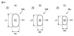
FIG. 13 is a cross-sectional view of the upper shell of the disc-type gas generator according to the fourth embodiment of the present invention, and FIG. 14 is an enlarged view of the first to third gas outlets shown in FIG. Hereinafter, the disc-type gas generator 1D according to the fourth embodiment of the present invention will be described with reference to FIGS. 13 and 14.

本実施の形態におけるディスク型ガス発生器1Dは、上述した実施の形態2におけるディスク型ガス発生器1Bとは異なり、標準的な大きさよりも大きい大型のエアバッグを膨張および展開させるタイプのものであり、図13に示すように、上部側シェル20の筒状部22には、上述した実施の形態2におけるディスク型ガス発生器1Bの場合よりも多い数のガス噴出口24が設けられている。 The disc-type gas generator 1D in the present embodiment is different from the disc-type gas generator 1B in the second embodiment described above, and is of a type that inflates and deploys a large airbag larger than the standard size. As shown in FIG. 13, the tubular portion 22 of the upper shell 20 is provided with a larger number of gas outlets 24 than in the case of the disc-type gas generator 1B in the second embodiment described above. ..

具体的には、図13に示すように、第1ガス噴出口24a、第2ガス噴出口24bおよび第3ガス噴出口24cは、上部側シェル20の筒状部22の周方向に沿って所定のルール(ただし、上述した実施の形態2において示したルールとは異なるルール)に従って一列に並んで設けられている。より詳細には、複数個のガス噴出口24は、その総数が32個であり、上部側シェル20の筒状部22の周方向に沿って所定の角度ごとに配置されている。 Specifically, as shown in FIG. 13, the first gas outlet 24a, the second gas outlet 24b, and the third gas outlet 24c are predetermined along the circumferential direction of the tubular portion 22 of the upper shell 20. (However, rules different from the rules shown in the second embodiment described above) are provided side by side in a row. More specifically, the plurality of gas outlets 24 have a total number of 32 and are arranged at predetermined angles along the circumferential direction of the tubular portion 22 of the upper shell 20.

第1ガス噴出口24aは、その数が8個であり、上部側シェル20の筒状部22の周方向に沿って70[°]、20[°]、70[°]、20[°]、・・・ごとに配置されている。第2ガス噴出口24bは、その数が8個であり、上部側シェル20の筒状部22の周方向に沿って30[°]、60[°]、30[°]、60[°]、・・・ごとに配置されている。第3ガス噴出口24cは、その数が16個であり、上部側シェル20の筒状部22の周方向に沿って20[°]、10[°]、20[°]、40[°]、20[°]、10[°]、20[°]、40[°]、・・・ごとに配置されている。 The number of the first gas outlets 24a is eight, and 70 [°], 20 [°], 70 [°], 20 [°] along the circumferential direction of the tubular portion 22 of the upper shell 20. , ... are arranged for each. The number of the second gas outlets 24b is eight, and the number is 30 [°], 60 [°], 30 [°], 60 [°] along the circumferential direction of the tubular portion 22 of the upper shell 20. , ... are arranged for each. The number of the third gas outlet 24c is 16, and the number is 20 [°], 10 [°], 20 [°], 40 [°] along the circumferential direction of the tubular portion 22 of the upper shell 20. , 20 [°], 10 [°], 20 [°], 40 [°], ...

ここで、第1ガス噴出口24a、第2ガス噴出口24bおよび第3ガス噴出口24cは、上部側シェル20の筒状部22の周方向に沿って、第1ガス噴出口24a、第3ガス噴出口24c、第2ガス噴出口24b、第3ガス噴出口24c、第3ガス噴出口24c、第2ガス噴出口24b、第3ガス噴出口24c、第1ガス噴出口24aの順でこれを1組として4組繰り返されるように配置されている。これにより、複数個のガス噴出口24は、上部側シェル20の筒状部22の周方向において互いに重ならないように配置されることになる。 Here, the first gas outlet 24a, the second gas outlet 24b, and the third gas outlet 24c are the first gas outlet 24a, the third gas outlet 24a, along the circumferential direction of the tubular portion 22 of the upper shell 20. This is in the order of gas outlet 24c, second gas outlet 24b, third gas outlet 24c, third gas outlet 24c, second gas outlet 24b, third gas outlet 24c, first gas outlet 24a. Are arranged so as to be repeated 4 sets with 1 set. As a result, the plurality of gas outlets 24 are arranged so as not to overlap each other in the circumferential direction of the tubular portion 22 of the upper shell 20.

なお、上述した第1ガス噴出口24a、第3ガス噴出口24c、第2ガス噴出口24b、第3ガス噴出口24c、第3ガス噴出口24c、第2ガス噴出口24b、第3ガス噴出口24c、第1ガス噴出口24a、第1ガス噴出口24a、・・・の順で配置された各ガス噴出口24間の配置間隔は、図示するように順に10[°]、10[°]、10[°]、10[°]、10[°]、10[°]、10[°]、20[°]、・・・とされている。 The first gas outlet 24a, the third gas outlet 24c, the second gas outlet 24b, the third gas outlet 24c, the third gas outlet 24c, the second gas outlet 24b, and the third gas injection described above. The arrangement intervals between the gas outlets 24 arranged in the order of the outlet 24c, the first gas outlet 24a, the first gas outlet 24a, ... Are 10 [°] and 10 [°] in order as shown in the figure. ], 10 [°], 10 [°], 10 [°], 10 [°], 10 [°], 20 [°], and so on.

ここで、図13を参照して、本実施の形態におけるディスク型ガス発生器1Dにおいては、互いに同一の開放圧を有することとなるように同一の形状でかつ同一の開口面積を有するように構成されたガス噴出口に着目してそれらの形成位置に応じて一纏まりのガス噴出口群としてこれを捉えた場合に、以下の複数組のガス噴出口群のみによって上述した複数個のガス噴出口24が構成されていると見ることができる。なお、当該ガス噴出口群の決定に際しては、上述したように、可能な限り多くのガス噴出口によって1組のガス噴出口群が構成されるようにこれを決定している。 Here, with reference to FIG. 13, the disk-type gas generator 1D in the present embodiment is configured to have the same shape and the same opening area so as to have the same opening pressure. When focusing on the gas outlets that have been formed and considering this as a group of gas outlets according to their formation positions, the above-mentioned plurality of gas outlets are provided only by the following plurality of gas outlet groups. It can be seen that 24 is configured. When determining the gas outlet group, as described above, it is determined so that a set of gas outlet groups is composed of as many gas outlets as possible.

第1ガス噴出口群X1:90[°]間隔で配置された合計4個のガス噴出口24a
第1ガス噴出口群X2:90[°]間隔で配置された合計4個のガス噴出口24a
第2ガス噴出口群Y1:90[°]間隔で配置された合計4個のガス噴出口24b
第2ガス噴出口群Y2:90[°]間隔で配置された合計4個のガス噴出口24b
第3ガス噴出口群Z1:90[°]間隔で配置された合計4個のガス噴出口24c
第3ガス噴出口群Z2:90[°]間隔で配置された合計4個のガス噴出口24c
第3ガス噴出口群Z3:90[°]間隔で配置された合計4個のガス噴出口24c
第3ガス噴出口群Z4:90[°]間隔で配置された合計4個のガス噴出口24c
First gas outlet group X1: A total of four gas outlets 24a arranged at 90 [°] intervals
First gas outlet group X2: A total of four gas outlets 24a arranged at 90 [°] intervals
Second gas outlet group Y1: A total of four gas outlets 24b arranged at 90 [°] intervals
Second gas outlet group Y2: A total of four gas outlets 24b arranged at 90 [°] intervals
Third gas outlet group Z1: A total of four gas outlets 24c arranged at intervals of 90 [°]
Third gas outlet group Z2: A total of four gas outlets 24c arranged at 90 [°] intervals
Third gas outlet group Z3: A total of four gas outlets 24c arranged at 90 [°] intervals.
Third gas outlet group Z4: A total of four gas outlets 24c arranged at 90 [°] intervals

すなわち、本実施の形態におけるディスク型ガス発生器1Dにおいては、複数個のガス噴出口24が、上部側シェル20の筒状部22の軸線を中心として120[°]以下の角度をもって回転対称性を有するように当該筒状部22の周方向に沿って均等に配置された互いに同一の開放圧を有する複数個のガス噴出口からなる合計で8組のガス噴出口群X1,X2,Y1,Y2,Z1,Z2,Z3,Z4のみにて構成されている。 That is, in the disk type gas generator 1D of the present embodiment, the plurality of gas outlets 24 have rotational symmetry at an angle of 120 [°] or less about the axis of the tubular portion 22 of the upper shell 20. A total of eight sets of gas outlet groups X1, X2, Y1, consisting of a plurality of gas outlets having the same opening pressure, which are evenly arranged along the circumferential direction of the tubular portion 22 so as to have. It is composed of only Y2, Z1, Z2, Z3 and Z4.

ここで、図13に示すように、本実施の形態におけるディスク型ガス発生器1Dにおいても、フランジ部23の最大外形位置Aから筒状部22の軸線Oに対して垂線PLを引いた場合(図13においては、4箇所の最大外形位置Aのうちの1箇所から垂線PLを引いた場合を代表的に図示している)に、当該垂線PLに最も近い位置に配置されたガス噴出口24が、第1ガス噴出口24a、第2ガス噴出口24bおよび第3ガス噴出口24cのうちの最も開口面積が大きい第1ガス噴出口24a以外のものとされている。 Here, as shown in FIG. 13, even in the disc-type gas generator 1D of the present embodiment, when a perpendicular line PL is drawn from the maximum external position A of the flange portion 23 with respect to the axis O of the tubular portion 22 ( In FIG. 13, the case where the perpendicular line PL is drawn from one of the four maximum external positions A is typically shown), and the gas ejection port 24 arranged at the position closest to the perpendicular line PL. However, among the first gas outlet 24a, the second gas outlet 24b, and the third gas outlet 24c, those other than the first gas outlet 24a having the largest opening area.

より具体的には、筒状部22の軸線Oに沿って見た場合に、筒状部22には、当該垂線PLに重なる位置にガス噴出口24は設けられておらず(すなわち、当該垂線PLと筒状部22の軸線Oとを含む平面上の位置に、複数個のガス噴出口24a〜24cのいずれもが配置されておらず)、これら筒状部22と垂線PLとの交点に最も近い位置には、第3ガス噴出口24cが配置されている。これにより、当該垂線PLに最も近い位置に配置されたガス噴出口24は、第1ガス噴出口24a、第2ガス噴出口24bおよび第3ガス噴出口24cのうちの最も開口面積が小さい第3ガス噴出口24cとされている。 More specifically, when viewed along the axis O of the tubular portion 22, the tubular portion 22 is not provided with the gas ejection port 24 at a position overlapping the perpendicular line PL (that is, the perpendicular wire). None of the plurality of gas outlets 24a to 24c is arranged at a position on a plane including the PL and the axis O of the tubular portion 22), at the intersection of these tubular portions 22 and the perpendicular line PL. The third gas outlet 24c is arranged at the nearest position. As a result, the gas outlet 24 arranged at the position closest to the perpendicular line PL has the third smallest opening area of the first gas outlet 24a, the second gas outlet 24b, and the third gas outlet 24c. It is said to be a gas outlet 24c.

したがって、本実施の形態におけるディスク型ガス発生器1Dとすることにより、上述した実施の形態2におけるディスク型ガス発生器1Bとした場合と同様に、その作動時において上部側シェル20の所定部位(特に、上述した領域Rのうちのフランジ部23の最大外形位置Aに対応する部分)に応力集中が発生することが飛躍的に軽減できることになる。そのため、当該構成を採用することにより、上部側シェル20の厚みを相対的に薄くすることが可能になり、結果として小型軽量化を実現することができる。 Therefore, by using the disc-type gas generator 1D in the present embodiment, as in the case of using the disc-type gas generator 1B in the above-described second embodiment, a predetermined portion of the upper shell 20 (at the time of its operation) In particular, it is possible to dramatically reduce the occurrence of stress concentration in the portion of the above-mentioned region R corresponding to the maximum external position A of the flange portion 23). Therefore, by adopting this configuration, the thickness of the upper shell 20 can be made relatively thin, and as a result, the size and weight can be reduced.

ここで、本実施の形態におけるディスク型ガス発生器1Dは、上述したように、標準的な大きさよりも大きい大型のエアバッグを膨張および展開させるタイプのものであり、上部側シェル20の筒状部22の外径は、たとえば70.0[mm]に設計され、当該筒状部22の厚み(板厚)は、たとえば1.3[mm]に設計される。 Here, the disc-type gas generator 1D in the present embodiment is of a type that inflates and deploys a large airbag larger than the standard size as described above, and has a tubular shape of the upper shell 20. The outer diameter of the portion 22 is designed to be, for example, 70.0 [mm], and the thickness (plate thickness) of the tubular portion 22 is designed to be, for example, 1.3 [mm].

この場合においては、図14を参照して、第1ガス噴出口24aの長さL1および幅W1は、たとえばそれぞれ3.7[mm]および2.0[mm]に設定され、第2ガス噴出口24bの長さL2および幅W2は、たとえばそれぞれ3.1[mm]および1.6[mm]に設定され、第3ガス噴出口24cの長さL3および幅W3は、たとえばそれぞれ2.5[mm]および1.4[mm]に設定される。 In this case, referring to FIG. 14, the length L1 and the width W1 of the first gas outlet 24a are set to, for example, 3.7 [mm] and 2.0 [mm], respectively, and the second gas injection. The length L2 and width W2 of the outlet 24b are set to, for example, 3.1 [mm] and 1.6 [mm], respectively, and the length L3 and width W3 of the third gas outlet 24c are set to, for example, 2.5, respectively. It is set to [mm] and 1.4 [mm].

なお、当該構成を採用した場合にも、1組の第1ガス噴出口群X1と2組の第3ガス噴出口群Z2,Z4とに含まれる合計で12個のガス噴出口を一度の打抜き処理にて形成するとともに、2組の第3ガス噴出口群Z1,Z3と1組の第1ガス噴出口群X2とに含まれる合計で12個のガス噴出口を一度の打抜き処理にて形成し、さらには2組の第2ガス噴出口群Y1,Y2に含まれる合計で8個のガス噴出口を一度の打抜き処理にて形成することにより、合計で3回の打抜き処理にて複数個のガス噴出口24のすべてを形成することが可能になり、プレス機の制約を加味した上での製造コストの最小化が実現できることになる。 Even when this configuration is adopted, a total of 12 gas outlets included in one set of the first gas outlet group X1 and two sets of the third gas outlet groups Z2 and Z4 are punched at one time. In addition to being formed by treatment, a total of 12 gas outlets included in two sets of third gas outlet groups Z1 and Z3 and one set of first gas outlet group X2 are formed by one punching process. Further, by forming a total of eight gas outlets included in the two sets of the second gas outlet groups Y1 and Y2 by one punching process, a plurality of gas ejection ports are formed by a total of three punching processes. It becomes possible to form all of the gas outlets 24 of the above, and the manufacturing cost can be minimized in consideration of the restrictions of the press machine.

(他の実施の形態等)
上述した本発明の実施の形態1ないし4においては、上部側シェルに複数個のガス噴出口およびフランジ部を設ける構成とした場合を例示して説明を行なったが、下部側シェルにこれらを設けることとしてもよい。
(Other embodiments, etc.)
In the above-described first to fourth embodiments of the present invention, a case where a plurality of gas outlets and flange portions are provided on the upper shell side has been described as an example, but these are provided on the lower shell side. It may be that.

また、上述した本発明の実施の形態1ないし4においては、ハウジングを上部側シェルおよび下部側シェルからなる一対のシェル部材にて構成した場合を例示して説明を行なったが、これを3つ以上のシェル部材にて構成することも当然に可能である。 Further, in the above-described first to fourth embodiments of the present invention, a case where the housing is composed of a pair of shell members including an upper shell and a lower shell has been described as an example. Of course, it is also possible to configure the shell members as described above.

また、上述した本発明の実施の形態1ないし4においては、互いに異なる開口面積を有するものが含まれた複数個のガス噴出口として、3種類のガス噴出口をハウジングに設けてなる場合を例示して説明を行なったが、これを2種類のガス噴出口にて構成することとしてもよいし、4種類以上のガス噴出口にて構成することとしてもよい。 Further, in the above-described first to fourth embodiments of the present invention, there is an example in which three types of gas outlets are provided in the housing as a plurality of gas outlets including those having different opening areas. As described above, this may be configured by two types of gas outlets, or may be configured by four or more types of gas outlets.

また、上述した本発明の実施の形態1ないし4においては、所定の規則的なルールに従って複数個のガス噴出口をハウジングに設けた場合を例示して説明を行なったが、ハウジングに設けられる複数個のガス噴出口は、必ずしも規則的なルールに従って設けられている必要はない。 Further, in the above-described first to fourth embodiments of the present invention, the case where a plurality of gas outlets are provided in the housing according to a predetermined regular rule has been described as an example. The gas outlets do not necessarily have to be provided according to regular rules.

さらには、上述した本発明の実施の形態1ないし4において開示したガス噴出口の形状、大きさ、レイアウト等は、本発明の趣旨を逸脱しない限りにおいて種々変更が可能である。 Further, the shape, size, layout and the like of the gas outlet disclosed in the above-described first to fourth embodiments of the present invention can be variously changed as long as the gist of the present invention is not deviated.

このように、今回開示した上記実施の形態はすべての点で例示であって、制限的なものではない。本発明の技術的範囲は特許請求の範囲によって画定され、また特許請求の範囲の記載と均等の意味および範囲内でのすべての変更を含むものである。 As described above, the above-described embodiment disclosed this time is an example in all respects and is not restrictive. The technical scope of the present invention is defined by the scope of claims and includes all modifications within the meaning and scope equivalent to the description of the scope of claims.

1A〜1D ディスク型ガス発生器、10 下部側シェル、11 底板部、12 筒状部、13 突状筒部、14 窪み部、15 開口部、20 上部側シェル、21 天板部、22 筒状部、23 フランジ部、24 ガス噴出口、24a 第1ガス噴出口、24b 第2ガス噴出口、24c 第3ガス噴出口、25 貫通孔、26 シールテープ、28 間隙部、30 保持部、31 内側被覆部、32 外側被覆部、33 連結部、34 雌型コネクタ部、40 点火器、41 点火部、42 端子ピン、50 カップ状部材、51 頂壁部、52 側壁部、53 延設部、54 先端部、55 伝火室、56 伝火薬、60 燃焼室、61 ガス発生剤、70 下部側支持部材、71 底部、72 当接部、73 先端部、80 上部側支持部材、81 底部、82 当接部、85 クッション材、90 フィルタ、A 最大外形位置、O 軸線、PL 垂線。 1A to 1D disk type gas generator, 10 lower shell, 11 bottom plate, 12 tubular, 13 protruding tubular, 14 recess, 15 opening, 20 upper shell, 21 top plate, 22 tubular Part, 23 Flange part, 24 gas outlet, 24a 1st gas outlet, 24b 2nd gas outlet, 24c 3rd gas outlet, 25 through hole, 26 sealing tape, 28 gap, 30 holding part, 31 inside Coating, 32 Outer coating, 33 Connecting, 34 Female connector, 40 Ignition, 41 Ignition, 42 Terminal pin, 50 Cup-shaped member, 51 Top wall, 52 Side wall, 53 Extension, 54 Tip, 55 Firebox, 56 Firebox, 60 Combustion Chamber, 61 Gas Generator, 70 Lower Support Member, 71 Bottom, 72 Abutment, 73 Tip, 80 Top Support Member, 81 Bottom, 82 Contact part, 85 cushion material, 90 filter, A maximum external position, O axis line, PL vertical line.

Claims (5)

周壁部、天板部および底板部を有し、前記周壁部の軸方向の両端が前記天板部および前記底板部によって閉塞されたハウジングと、
前記ハウジングの内部に配置され、燃焼することでガスを発生させるガス発生剤と、
前記ハウジングに組付けられ、前記ガス発生剤を燃焼させるための点火器とを備え、
前記ハウジングは、複数のシェル部材が組み合わされて接合されることで構成され、
前記複数のシェル部材のうちの1つは、前記周壁部の少なくとも一部を構成する筒状部と、前記筒状部の軸方向における一端から径方向外側に向けて連続して延びるフランジ部とを少なくとも有し、
前記筒状部には、互いに異なる開口面積を有するものが含まれた複数個のガス噴出口が設けられ、
前記フランジ部は、前記筒状部の軸線から当該フランジ部の外縁までの距離が非一様となる形状に構成され、
前記フランジ部の外縁のうち、前記筒状部の軸線から最も遠い位置である最大外形位置から、前記筒状部の軸線に対して垂線を引いた場合に、前記垂線と前記筒状部の軸線とを含む平面上の位置に、前記複数個のガス噴出口のいずれもが配置されておらず、かつ、前記垂線を挟み込むように前記垂線に最も近い位置に配置された一対のガス噴出口が、いずれも前記複数個のガス噴出口のうちの最も開口面積が大きいもの以外のものである条件を満たし、
前記最大外形位置が、前記筒状部の周方向に沿って複数存在し、
前記複数の最大外形位置に対応した部分の各々において、前記条件が満たされている、ガス発生器。
A housing having a peripheral wall portion, a top plate portion, and a bottom plate portion, and both ends of the peripheral wall portion in the axial direction are closed by the top plate portion and the bottom plate portion.
A gas generator that is placed inside the housing and generates gas by burning,
Assembled to the housing and provided with an igniter for burning the gas generating agent.
The housing is configured by combining and joining a plurality of shell members.
One of the plurality of shell members includes a tubular portion that forms at least a part of the peripheral wall portion, and a flange portion that continuously extends from one end of the tubular portion in the axial direction toward the outside in the radial direction. Have at least
The tubular portion is provided with a plurality of gas outlets including those having different opening areas.
The flange portion is configured such that the distance from the axis of the tubular portion to the outer edge of the flange portion is non-uniform.
When a perpendicular line is drawn with respect to the axis of the tubular portion from the maximum external position which is the position farthest from the axis of the tubular portion of the outer edge of the flange portion, the perpendicular line and the axis of the tubular portion are drawn. Neither of the plurality of gas outlets is arranged at a position on a plane including the above, and a pair of gas outlets arranged at positions closest to the perpendicular so as to sandwich the perpendicular. , All satisfy the condition that the opening area is other than the one having the largest opening area among the plurality of gas outlets.
A plurality of the maximum external positions are present along the circumferential direction of the tubular portion.
A gas generator in which the above conditions are satisfied in each of the portions corresponding to the plurality of maximum external positions.
周壁部、天板部および底板部を有し、前記周壁部の軸方向の両端が前記天板部および前記底板部によって閉塞されたハウジングと、
前記ハウジングの内部に配置され、燃焼することでガスを発生させるガス発生剤と、
前記ハウジングに組付けられ、前記ガス発生剤を燃焼させるための点火器とを備え、
前記ハウジングは、複数のシェル部材が組み合わされて接合されることで構成され、
前記複数のシェル部材のうちの1つは、前記周壁部の少なくとも一部を構成する筒状部と、前記筒状部の軸方向における一端から径方向外側に向けて連続して延びるフランジ部とを少なくとも有し、
前記筒状部には、互いに異なる開口面積を有するものが含まれた複数個のガス噴出口が設けられ、
前記フランジ部は、前記筒状部の軸線から当該フランジ部の外縁までの距離が非一様となる形状に構成され、
前記フランジ部の外縁のうち、前記筒状部の軸線から最も遠い位置である最大外形位置から、前記筒状部の軸線に対して垂線を引いた場合に、前記垂線上に、前記複数個のガス噴出口のうちの最も開口面積が大きいもの以外のものが配置されている、ガス発生器。
A housing having a peripheral wall portion, a top plate portion, and a bottom plate portion, and both ends of the peripheral wall portion in the axial direction are closed by the top plate portion and the bottom plate portion.
A gas generator that is placed inside the housing and generates gas by burning,
Assembled to the housing and provided with an igniter for burning the gas generating agent.
The housing is configured by combining and joining a plurality of shell members.
One of the plurality of shell members includes a tubular portion that forms at least a part of the peripheral wall portion, and a flange portion that continuously extends from one end of the tubular portion in the axial direction toward the outside in the radial direction. Have at least
The tubular portion is provided with a plurality of gas outlets including those having different opening areas.
The flange portion is configured such that the distance from the axis of the tubular portion to the outer edge of the flange portion is non-uniform.
When a perpendicular line is drawn with respect to the axis of the tubular portion from the maximum external position which is the position farthest from the axis of the tubular portion among the outer edges of the flange portion, the plurality of said A gas generator in which a gas outlet other than the one with the largest opening area is arranged.
前記フランジ部には、当該ガス発生器を外部の部材にて対して固定するための貫通孔が設けられ、
前記筒状部の軸線から前記フランジ部の外縁までの距離が、前記フランジ部の前記貫通孔が設けられた部分において、前記フランジ部の前記貫通孔が設けられていない部分よりも大きく構成されている、請求項1または2に記載のガス発生器。
The flange portion is provided with a through hole for fixing the gas generator to an external member.
The distance from the axis of the tubular portion to the outer edge of the flange portion is configured to be larger in the portion of the flange portion provided with the through hole than in the portion of the flange portion not provided with the through hole. The gas generator according to claim 1 or 2.
前記複数個のガス噴出口が、前記筒状部の周方向に沿って一列に並んで配置されている、請求項1から3のいずれかに記載のガス発生器。 The gas generator according to any one of claims 1 to 3, wherein the plurality of gas outlets are arranged side by side in a row along the circumferential direction of the tubular portion. 前記ハウジングが、前記複数のシェル部材として、前記天板部および前記天板部寄りの前記周壁部を構成する有底筒状の上部側シェルと、前記底板部および前記底板部寄りの前記周壁部を構成する有底筒状の下部側シェルとを含み、
前記複数個のガス噴出口が設けられた前記筒状部が、前記天板部寄りの前記周壁部を構成する部分の前記上部側シェルによって規定され、
前記フランジ部が、前記天板部寄りの前記周壁部を構成する部分の前記上部側シェルの前記底板部側の端部から延設され、
前記底板部寄りの前記周壁部を構成する部分の前記下部側シェルが、前記天板部寄りの前記周壁部を構成する部分の前記上部側シェルに内挿されることで、前記上部側シェルと前記下部側シェルとが組み合わされ、
前記点火器が、前記底板部を構成する部分の前記下部側シェルに組付けられている、請求項1から4のいずれかに記載のガス発生器。
As the plurality of shell members, the housing comprises a bottomed tubular upper shell constituting the top plate portion and the peripheral wall portion near the top plate portion, and the peripheral wall portion near the bottom plate portion and the bottom plate portion. Including the bottomed tubular lower shell that constitutes
The tubular portion provided with the plurality of gas outlets is defined by the upper shell of the portion constituting the peripheral wall portion near the top plate portion.
The flange portion extends from the end portion of the upper shell portion of the portion constituting the peripheral wall portion near the top plate portion on the bottom plate portion side.
The lower shell of the portion constituting the peripheral wall portion near the bottom plate portion is inserted into the upper shell of the portion constituting the peripheral wall portion near the top plate portion, whereby the upper shell and the upper shell are described. Combined with the lower shell,
The gas generator according to any one of claims 1 to 4, wherein the igniter is assembled to the lower shell of a portion constituting the bottom plate portion.
JP2021030356A 2021-02-26 2021-02-26 gas generator Active JP7130076B2 (en)

Priority Applications (1)

Application Number Priority Date Filing Date Title
JP2021030356A JP7130076B2 (en) 2021-02-26 2021-02-26 gas generator

Applications Claiming Priority (1)

Application Number Priority Date Filing Date Title
JP2021030356A JP7130076B2 (en) 2021-02-26 2021-02-26 gas generator

Related Parent Applications (1)

Application Number Title Priority Date Filing Date
JP2017073832A Division JP6910828B2 (en) 2017-04-03 2017-04-03 Gas generator

Publications (2)

Publication Number Publication Date
JP2021079950A true JP2021079950A (en) 2021-05-27
JP7130076B2 JP7130076B2 (en) 2022-09-02

Family

ID=75963972

Family Applications (1)

Application Number Title Priority Date Filing Date
JP2021030356A Active JP7130076B2 (en) 2021-02-26 2021-02-26 gas generator

Country Status (1)

Country Link
JP (1) JP7130076B2 (en)

Cited By (1)

* Cited by examiner, † Cited by third party
Publication number Priority date Publication date Assignee Title
WO2024005079A1 (en) * 2022-06-28 2024-01-04 株式会社ダイセル Gas generator and gas discharge method for gas generator

Citations (4)

* Cited by examiner, † Cited by third party
Publication number Priority date Publication date Assignee Title
JP2003516891A (en) * 1999-08-12 2003-05-20 ブリード・オートモティブ・テクノロジィ・インク Two-stage airbag inflator
JP2008149873A (en) * 2006-12-18 2008-07-03 Daicel Chem Ind Ltd Gas generator and personnel restraint device using the same
US20130200600A1 (en) * 2010-10-15 2013-08-08 Trw Airbag Systems Gmbh Gas generator and airbag module
WO2015163290A1 (en) * 2014-04-25 2015-10-29 日本化薬株式会社 Gas generator

Patent Citations (4)

* Cited by examiner, † Cited by third party
Publication number Priority date Publication date Assignee Title
JP2003516891A (en) * 1999-08-12 2003-05-20 ブリード・オートモティブ・テクノロジィ・インク Two-stage airbag inflator
JP2008149873A (en) * 2006-12-18 2008-07-03 Daicel Chem Ind Ltd Gas generator and personnel restraint device using the same
US20130200600A1 (en) * 2010-10-15 2013-08-08 Trw Airbag Systems Gmbh Gas generator and airbag module
WO2015163290A1 (en) * 2014-04-25 2015-10-29 日本化薬株式会社 Gas generator

Cited By (1)

* Cited by examiner, † Cited by third party
Publication number Priority date Publication date Assignee Title
WO2024005079A1 (en) * 2022-06-28 2024-01-04 株式会社ダイセル Gas generator and gas discharge method for gas generator

Also Published As

Publication number Publication date
JP7130076B2 (en) 2022-09-02

Similar Documents

Publication Publication Date Title
JP6585586B2 (en) Gas generator
JP6683455B2 (en) Gas generator
JP6910828B2 (en) Gas generator
JP6798935B2 (en) Gas generator
CN108698556B (en) The gas generator
JP6250434B2 (en) Gas generator
CN116802088B (en) Gas generator
JP6084096B2 (en) Gas generator
JP2021079950A (en) Gas generator
JP7240943B2 (en) gas generator
JP7587443B2 (en) Igniters and gas generators
JP6618775B2 (en) Gas generator
JP6681772B2 (en) Gas generator
JP6857765B2 (en) Gas generator
JP6084095B2 (en) Gas generator
JP6947580B2 (en) Gas generator
JP7758566B2 (en) Gas generator
JP7478705B2 (en) Gas generator
JP2021138173A (en) Gas generator
JP2020131910A (en) Gas generator

Legal Events

Date Code Title Description
A621 Written request for application examination

Free format text: JAPANESE INTERMEDIATE CODE: A621

Effective date: 20210226

A977 Report on retrieval

Free format text: JAPANESE INTERMEDIATE CODE: A971007

Effective date: 20220208

A131 Notification of reasons for refusal

Free format text: JAPANESE INTERMEDIATE CODE: A131

Effective date: 20220222

A521 Request for written amendment filed

Free format text: JAPANESE INTERMEDIATE CODE: A523

Effective date: 20220404

TRDD Decision of grant or rejection written
A01 Written decision to grant a patent or to grant a registration (utility model)

Free format text: JAPANESE INTERMEDIATE CODE: A01

Effective date: 20220802

A61 First payment of annual fees (during grant procedure)

Free format text: JAPANESE INTERMEDIATE CODE: A61

Effective date: 20220823

R150 Certificate of patent or registration of utility model

Ref document number: 7130076

Country of ref document: JP

Free format text: JAPANESE INTERMEDIATE CODE: R150

R250 Receipt of annual fees

Free format text: JAPANESE INTERMEDIATE CODE: R250