JP2021020529A - Drone - Google Patents
Drone Download PDFInfo
- Publication number
- JP2021020529A JP2021020529A JP2019137475A JP2019137475A JP2021020529A JP 2021020529 A JP2021020529 A JP 2021020529A JP 2019137475 A JP2019137475 A JP 2019137475A JP 2019137475 A JP2019137475 A JP 2019137475A JP 2021020529 A JP2021020529 A JP 2021020529A
- Authority
- JP
- Japan
- Prior art keywords
- drone
- luggage
- destination
- charged
- electric line
- Prior art date
- Legal status (The legal status is an assumption and is not a legal conclusion. Google has not performed a legal analysis and makes no representation as to the accuracy of the status listed.)
- Pending
Links
Images


Classifications
-
- Y—GENERAL TAGGING OF NEW TECHNOLOGICAL DEVELOPMENTS; GENERAL TAGGING OF CROSS-SECTIONAL TECHNOLOGIES SPANNING OVER SEVERAL SECTIONS OF THE IPC; TECHNICAL SUBJECTS COVERED BY FORMER USPC CROSS-REFERENCE ART COLLECTIONS [XRACs] AND DIGESTS
- Y02—TECHNOLOGIES OR APPLICATIONS FOR MITIGATION OR ADAPTATION AGAINST CLIMATE CHANGE
- Y02T—CLIMATE CHANGE MITIGATION TECHNOLOGIES RELATED TO TRANSPORTATION
- Y02T50/00—Aeronautics or air transport
- Y02T50/60—Efficient propulsion technologies, e.g. for aircraft
Landscapes
- Charge And Discharge Circuits For Batteries Or The Like (AREA)
Abstract
【課題】荷物を長距離輸送できるドローンを提供する。
【解決手段】
ドローン1は、荷物Lを目的地Dに搬送する。ドローン1は、ドローン本体2と、荷物Lを積載するトランク3とを備える。ドローン1は、荷物Lを目的地Dに搬送するときに、商用電力の電線路Eに沿って飛行し、電線路Eを流れる商用電力を利用して充電できる。そのため、電線路Eを流れる商用電力を利用して充電しつつ、荷物Lを目的地Dに搬送でき、荷物Lを長距離輸送できる。
【選択図】図2PROBLEM TO BE SOLVED: To provide a drone capable of transporting a luggage over a long distance.
SOLUTION:
The drone 1 transports the luggage L to the destination D. The drone 1 includes a drone main body 2 and a trunk 3 for loading a luggage L. When the luggage L is transported to the destination D, the drone 1 flies along the electric line E of commercial electric power and can be charged by using the commercial electric power flowing through the electric line E. Therefore, the luggage L can be transported to the destination D and the luggage L can be transported over a long distance while being charged by using the commercial power flowing through the electric line E.
[Selection diagram] Fig. 2
Description
本発明は、ドローンに関する。 The present invention relates to a drone.
従来、無人飛行体を用いた輸送システムが提案されている。無人飛行体は、荷物を収容するコンテナを装着しながら飛行する。コンテナは、無人飛行体に給電するための蓄電部を備える(下記特許文献1参照)
Conventionally, a transportation system using an unmanned aerial vehicle has been proposed. The unmanned aerial vehicle flies with a container for accommodating luggage. The container includes a power storage unit for supplying power to the unmanned aerial vehicle (see
上記した特許文献1に記載の輸送システムでは、コンテナの蓄電部に蓄電される電力によって、無人飛行体の飛行範囲が制限される。そのため、荷物の長距離輸送が困難である。
In the transportation system described in
そこで、本発明の目的は、荷物を長距離輸送できるドローンを提供することにある。 Therefore, an object of the present invention is to provide a drone capable of transporting a load over a long distance.
本発明は、荷物を目的地に搬送するためのドローンであって、ドローン本体と、前記荷物を積載することができる積載部とを備え、前記荷物を前記目的地に搬送するときに、商用電力の電線路に沿って飛行し、前記電線路を流れる商用電力を利用して充電できる、ドローンを含む。 The present invention is a drone for transporting a load to a destination, and includes a drone main body and a loading unit capable of loading the load, and when the load is transported to the destination, commercial power is supplied. Includes drones that fly along power lines and can be charged using commercial power flowing through the power lines.
このような構成によれば、ドローンは、荷物を目的地に搬送するときに、商用電力の電線路に沿って飛行する。そして、電線路を流れる商用電力を利用して充電できる。 According to such a configuration, the drone flies along the commercial power line when transporting the luggage to the destination. Then, it can be charged by using the commercial power flowing through the electric line.
そのため、電線路を流れる商用電力を利用して充電しつつ、荷物を長距離輸送できる。 Therefore, it is possible to transport luggage over a long distance while charging using commercial power flowing through an electric line.
本発明のドローンによれば、荷物を長距離輸送できる。 According to the drone of the present invention, luggage can be transported over a long distance.
1.ドローン1
図1を参照して、ドローン1について説明する。
1. 1.
The
ドローン1は、ドローン本体2と、積載部の一例としてのトランク3と、受電部4とを備える。
The
(1)ドローン本体2
ドローン本体2は、公知のドローンと同様の構造を有する。詳しくは、ドローン本体2は、筐体5と、複数のプロペラ6とを備える。
(1) Drone body 2
The drone body 2 has a structure similar to that of a known drone. Specifically, the drone main body 2 includes a housing 5 and a plurality of
筐体5は、ドローン1の動力部および制御部を収容する。詳しくは、筐体5は、バッテリー(図示せず)、電力分配基板(図示せず)、および、各プロペラ6のモータ(図示せず)などから構成される動力部と、制御基板(図示せず)、受信機(図示せず)およびGPS(全地球測位システム、図示せず)などから構成される制御部とを収容する。電力分配基板は、制御基板によって制御され、バッテリーからの電力を各プロペラ6のモータに分配する。受信機およびGPSは、制御基板と通信可能である。
The housing 5 houses the power unit and the control unit of the
複数のプロペラ6のそれぞれは、筐体5に取り付けられる。詳しくは、複数のプロペラ6のそれぞれは、筐体5内に取り付けられるモータ(図示せず)のシャフトに取り付けられる。なお、複数のプロペラ6のぞれぞれは、筐体5から延びるアームに取り付けられてもよい。
Each of the plurality of
(2)トランク3
トランク3は、ドローン本体2に取り付けられる。なお、トランク3は、ドローン本体2に設けられてもよい。トランク3は、荷物Lを積載することができる。詳しくは、トランク3は、荷物Lを収容することができる。トランク3は、例えば、筐体5の上面に設けられる。トランク3は、筐体5の下面に設けられてもよい。
(2) Trunk 3
The trunk 3 is attached to the drone body 2. The trunk 3 may be provided on the drone body 2. The trunk 3 can carry the luggage L. Specifically, the trunk 3 can accommodate the luggage L. The trunk 3 is provided on the upper surface of the housing 5, for example. The trunk 3 may be provided on the lower surface of the housing 5.
(3)受電部4
受電部4は、ドローン本体2に取り付けられる。なお、受電部4は、ドローン本体2に設けられてもよい。受電部4は、筐体5内のバッテリーと電気的に接続される。受電部4に供給された電力は、バッテリーに充電される。受電部4は、例えば、筐体5の下面から下方に突出する。
(3) Power receiving unit 4
The power receiving unit 4 is attached to the drone body 2. The power receiving unit 4 may be provided on the drone main body 2. The power receiving unit 4 is electrically connected to the battery in the housing 5. The electric power supplied to the power receiving unit 4 is charged into the battery. The power receiving unit 4 projects downward from the lower surface of the housing 5, for example.
2.配送システム10
図2および図3を参照して、ドローン1を用いた配送システム10について説明する。
2. 2.
The
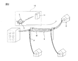
図2に示すように、配送システム10は、少なくとも1つのドローン1と、ドローン1を管制する管制システム11とを備える。管制システム11は、ドローン1の位置情報、商用電力の電線路Eの地図情報、および気象情報などに基づいて、ドローン1の飛行を管制する。ドローン1は、管制システム11の管制に従って、荷物Lを目的地Dに搬送する。
As shown in FIG. 2, the
ドローン1は、荷物Lを目的地Dに搬送するときに、管制システム11の管制に従って、商用電力の電線路Eに沿って飛行する。なお、ドローン1は、電線路Eを構成する電線Wから発せられる電磁波を検知することにより、管制システム11の管制によらずに自律して、商用電力の電線路Eに沿って飛行してもよい。また、「商用電力の電線路Eに沿って」とは、電線路Eを構成する電線Wを自由に選択して、飛行ルートを設定できることを意味する。すなわち、ドローン1が飛行可能な距離であれば、互いに離れた一の電線Wから他の電線Wへ向かって、一時的に電線Wに沿わないで飛行することもできる。
When the luggage L is transported to the destination D, the
そして、ドローン1は、電線路Eを流れる商用電力を利用して充電できる。この実施形態では、図3に示すように、電線Wを支持する電柱Pに、ドローン1が着陸できる充電ポートCが設けられる。充電ポートCは、電線Wと電気的に接続されている。ドローン1が充電ポートCに着陸した状態で、ドローン1の受電部4は、充電ポートCの端子Tと接触する。ドローン1の受電部4が充電ポートCの端子Tと接触することにより、電線Wを流れる商用電力が、充電ポートCを介して受電部4に供給される。これにより、ドローン1は、電線路Eを流れる商用電力を利用して充電できる。
Then, the
3.作用効果
ドローン1は、図2に示すように、荷物Lを目的地Dに搬送するときに、商用電力の電線路Eに沿って飛行する。そして、図3に示すように、電柱Pに設けられる充電ポートCで、電線路Eを流れる商用電力を利用して充電できる。
3. 3. Action Effect As shown in FIG. 2, the
そのため、電線路Eを流れる商用電力を利用して充電しつつ、荷物Lを長距離輸送できる。 Therefore, the luggage L can be transported over a long distance while being charged by using the commercial power flowing through the electric line E.
また、電線Wの下(例えば、道路の端)は、電柱Pが立っていることから、車や歩行者の往来が少ない。そのため、電線Wに沿ってドローン1が飛行していれば、万が一、ドローン1が墜落したり、搬送中の荷物Lが落下したりしても、車や歩行者に衝突する可能性が低い。その結果、ドローン1によって、荷物Lを安全に搬送できる。
Further, since the utility pole P stands under the electric wire W (for example, at the end of the road), the traffic of cars and pedestrians is small. Therefore, if the
4.変形例
(1)積載部は、荷物を積載できれば、トランク3に限定されない。積載部は、荷物Lを固定することができる荷台であってもよい。積載部は、荷物Lを吊り下げることができるフックであってもよい。
4. Modification example (1) The loading portion is not limited to the trunk 3 as long as it can load luggage. The loading unit may be a loading platform on which the luggage L can be fixed. The loading portion may be a hook capable of suspending the luggage L.
(2)ドローン1の充電手段は、電柱Pに設けられる充電ポートCに限られない。例えば、図4に示すように、ドローン1は、電線Wに受電部4を接触させることにより、充電してもよい。また、ドローン1は、飛行しながら充電してもよい。また、ドローン1は、充電ポートCまたは電線Wと接触せずに、充電(ワイヤレス充電)してもよい。非接触の充電方式としては、例えば、電磁誘導方式、磁界共振方式などの非放射型の充電方式が挙げられる。
(2) The charging means of the
1 ドローン
2 ドローン本体
3 トランク
D 目的地
E 電線路
L 荷物
1 Drone 2 Drone body 3 Trunk D Destination E Electric line L Luggage
Claims (1)
ドローン本体と、
前記荷物を積載する積載部と
を備え、
前記荷物を前記目的地に搬送するときに、商用電力の電線路に沿って飛行し、前記電線路を流れる商用電力を利用して充電できることを特徴とする、ドローン。 A drone for transporting luggage to a destination
With the drone body
It is equipped with a loading unit for loading the luggage.
A drone characterized in that when the luggage is transported to the destination, it can fly along an electric line of commercial electric power and can be charged by using the commercial electric power flowing through the electric line.
Priority Applications (1)
| Application Number | Priority Date | Filing Date | Title |
|---|---|---|---|
| JP2019137475A JP2021020529A (en) | 2019-07-26 | 2019-07-26 | Drone |
Applications Claiming Priority (1)
| Application Number | Priority Date | Filing Date | Title |
|---|---|---|---|
| JP2019137475A JP2021020529A (en) | 2019-07-26 | 2019-07-26 | Drone |
Publications (1)
| Publication Number | Publication Date |
|---|---|
| JP2021020529A true JP2021020529A (en) | 2021-02-18 |
Family
ID=74573908
Family Applications (1)
| Application Number | Title | Priority Date | Filing Date |
|---|---|---|---|
| JP2019137475A Pending JP2021020529A (en) | 2019-07-26 | 2019-07-26 | Drone |
Country Status (1)
| Country | Link |
|---|---|
| JP (1) | JP2021020529A (en) |
Cited By (4)
| Publication number | Priority date | Publication date | Assignee | Title |
|---|---|---|---|---|
| JP2022072635A (en) * | 2020-10-30 | 2022-05-17 | 株式会社ダイヘン | Non-contact power transmission system and non-contact power supply system |
| WO2023026616A1 (en) | 2021-08-23 | 2023-03-02 | 株式会社エアロネクスト | Flying object |
| JP2023155556A (en) * | 2022-04-11 | 2023-10-23 | 株式会社荏原製作所 | Aerial power supply system for drones |
| US12434816B2 (en) | 2021-08-23 | 2025-10-07 | Aeronext Inc. | Flying object with backward-tilting delivery payload mechanism |
Citations (2)
| Publication number | Priority date | Publication date | Assignee | Title |
|---|---|---|---|---|
| US20170015415A1 (en) * | 2015-07-15 | 2017-01-19 | Elwha Llc | System and method for operating unmanned aircraft |
| JP2019028712A (en) * | 2017-07-31 | 2019-02-21 | 株式会社Aerial Lab Industries | Aircraft guidance method, guidance device, and guidance system |
-
2019
- 2019-07-26 JP JP2019137475A patent/JP2021020529A/en active Pending
Patent Citations (2)
| Publication number | Priority date | Publication date | Assignee | Title |
|---|---|---|---|---|
| US20170015415A1 (en) * | 2015-07-15 | 2017-01-19 | Elwha Llc | System and method for operating unmanned aircraft |
| JP2019028712A (en) * | 2017-07-31 | 2019-02-21 | 株式会社Aerial Lab Industries | Aircraft guidance method, guidance device, and guidance system |
Cited By (4)
| Publication number | Priority date | Publication date | Assignee | Title |
|---|---|---|---|---|
| JP2022072635A (en) * | 2020-10-30 | 2022-05-17 | 株式会社ダイヘン | Non-contact power transmission system and non-contact power supply system |
| WO2023026616A1 (en) | 2021-08-23 | 2023-03-02 | 株式会社エアロネクスト | Flying object |
| US12434816B2 (en) | 2021-08-23 | 2025-10-07 | Aeronext Inc. | Flying object with backward-tilting delivery payload mechanism |
| JP2023155556A (en) * | 2022-04-11 | 2023-10-23 | 株式会社荏原製作所 | Aerial power supply system for drones |
Similar Documents
| Publication | Publication Date | Title |
|---|---|---|
| US11748688B2 (en) | Drone based delivery system using vehicles | |
| US20230376883A1 (en) | Vehicle-associated package repository for drone based delivery systems | |
| US20200039373A1 (en) | Systems and methods for charging an unmanned aerial vehicle with a host vehicle | |
| JP2021020529A (en) | Drone | |
| US10632852B2 (en) | Electric vehicle optical charging system and method of use | |
| US10427530B2 (en) | Vehicle charge query and exchange system and method of use | |
| US20190025830A1 (en) | Wireless charging and protection for unmanned delivery aerial vehicles | |
| GB2530626A (en) | Unmanned aerial vehicle deployment system and method of control | |
| CN110209189A (en) | Flight control assemblies, storage medium and vehicle | |
| WO2022110116A1 (en) | Flight charging method and system and charging unmanned aerial vehicle | |
| CN119284245A (en) | Methods and systems for using unmanned aerial vehicles (UAVs) | |
| US20210394904A1 (en) | Unmanned aerial vehicles | |
| KR101867424B1 (en) | Wireless power charging apparatus transmitting power wirelessly for drones airborne | |
| JP2019020770A (en) | Information processing apparatus, flying object, transportation network generation method, transportation method, program, and recording medium | |
| US20250340218A1 (en) | Delivery Hand Off Procedure When Electric Vehicle (EV) is About to Lose Power | |
| US20210214078A1 (en) | Transportation system and transportation management server, flying body, and travelling body | |
| JP6680450B1 (en) | Unmanned aerial vehicle power supply system and unmanned power supply vehicle | |
| WO2023194993A1 (en) | Devices, systems and methods for in-flight recharging of an electric aerial vehicle | |
| JP7276117B2 (en) | Systems, units and information processing equipment | |
| CN112591088B (en) | A method and device for waterway unmanned transportation | |
| JP6680451B1 (en) | Unmanned aerial vehicle power supply system and unmanned power supply vehicle | |
| KR20230055713A (en) | Mobility operating system to circumstances | |
| CN112758313A (en) | Method, device and equipment for relay passenger carrying of gyroplane and storage medium | |
| JP2016067181A (en) | Management device, management method and program for the same, and power supply system | |
| KR102172209B1 (en) | Drone Reconnaissance System For Long-Distance Ocean |
Legal Events
| Date | Code | Title | Description |
|---|---|---|---|
| A621 | Written request for application examination |
Free format text: JAPANESE INTERMEDIATE CODE: A621 Effective date: 20220216 |
|
| A977 | Report on retrieval |
Free format text: JAPANESE INTERMEDIATE CODE: A971007 Effective date: 20221222 |
|
| A131 | Notification of reasons for refusal |
Free format text: JAPANESE INTERMEDIATE CODE: A131 Effective date: 20221227 |
|
| A521 | Request for written amendment filed |
Free format text: JAPANESE INTERMEDIATE CODE: A523 Effective date: 20230222 |
|
| A02 | Decision of refusal |
Free format text: JAPANESE INTERMEDIATE CODE: A02 Effective date: 20230425 |